


PVG
http://waterheatertimer.org/How-to-install-gas-water-heater.html#troubleshoot
INSTALLATION, OPERATION, AND SERVICE MANUAL
POWER VENT STORAGE TYPE GAS WATER HEATER
MODELS PVG/PVCG
THESE INSTRUCTIONS ARE INTENDED AS AN AID TO
QUALIFIED SERVICE PERSONNEL FOR PROPER INSTALLATION,
ADJUSTMENT AND OPERATION OF THIS WATER HEATER.
READ THESE INSTRUCTIONS THOROUGHLY BEFORE
ATTEMPTING INSTALLATION OR OPERATION. FAILURE TO
FOLLOW THESE INSTRUCTIONS MAY RESULT IN IMPROPER
INSTALLATION, OPERATION, SERVICE OR MAINTENANCE,
POSSIBLY RESULTING IN FIRE, ELECTRICAL SHOCK, SCALD
INJURY, CARBON MONOXIDE POISONING, EXPLOSION,
PROPERTY DAMAGE, PERSONAL INJURY OR DEATH.
INSTALLER:
• ATTACH THESE INSTRUCTIONS TO OR ADJACENT TO THE
WATER HEATER.
• BEFORE LEAVING THE PREMISES REVIEW THIS INSTALLATION,
OPERATION AND SERVICE MANUAL TO BE SURE THE HEATER
HAS BEEN INSTALLED CORRECTLY. START AND OPERATE THE
UNIT FOR ONE COMPLETE CYCLE AND MAKE SURE THE
WATER TEMPERATURE IS ACCEPTABLE TO THE CONSUMER
AT THE FIXTURES.
OWNER:
• RETAIN THESE INSTRUCTIONS AND WARRANTY FOR FUTURE
REFERENCE. RETAIN THE ORIGINAL RECEIPT AS PROOF OF
PURCHASE.
THIS MANUAL IS NOT TO BE USED WITH GAS STORAGE TYPE
WATER HEATERS CERTIFIED FOR INSTALLATION IN
MANUFACTURED HOMES (MOBILE HOMES).
Recognize this symbol as an indication of Important Safety
Information.
WARNING: If the information in these
instructions is not followed exactly, a fire or
explosion may result causing property damage,
personal injury or death.
Do not store or use gasoline or other flammable
vapors and liquids in the vicinity of this or any
other appliance.
WHAT TO DO IF YOU SMELL GAS
• Do not try to light any appliance.
• Do not touch any electrical switch; do not use
any telephone in your building.
• Immediately call your gas supplier from a
neighbor’s telephone. Follow the gas
supplier’s instructions.
• If you cannot reach your gas supplier, call the
fire department.
Installation and service must be performed by a
qualified installer, service agency or the gas
supplier.
AN ODORANT IS ADDED BY THE GAS SUPPLIER TO THE GAS
USED BY THIS WATER HEATER.
WARNING
AN ODORANT IS ADDED BY THE GAS SUPPLIER TO THE GAS USED BY
THIS WATER HEATER. THIS ODORANT MAY FADE OVER AN
EXTENDED PERIOD OF TIME. DO NOT DEPEND UPON THIS ODORANT
AS AN INDICATION OF LEAKING GAS. IF A GAS LEAK IS SUSPECTED,
CHECK FOR LEAKS BY USING A CHLORIDE-FREE SOAP AND WATER
SOLUTION, OR OTHER APPROVED METHOD. IF A LEAK CANNOT BE
FOUND BUT IS STILL SUSPECTED, FOLLOW THE STEPS UNDER
"WHAT TO DO IF YOU SMELL GAS" AS OUTLINED ON THIS PAGE.
FAILURE TO OBSERVE THIS WARNING COULD RESULT IN PROPERTY
DAMAGE, PERSONAL INJURY, OR DEATH.
WARNING
THIS WATER HEATER MUST BE BRACED, ANCHORED, OR
STRAPPED TO AVOID FALLING OR MOVING DURING AN
EARTHQUAKE. CONTACT LOCAL UTILITIES FOR CODE
REQUIREMENTS IN YOUR AREA OR CALL THE 800 NUMBER
SHOWN ON FRONT OF THIS MANUAL AND REQUEST
INSTRUCTIONS 6600933 FOR EXAMPLES.
TO OBTAIN TECHNICAL, WARRANTY OR SERVICE
ASSISTANCE DURING OR AFTER THE INSTALLATION OF
THIS WATER HEATER, CALL TOLL FREE
1-800-999-9515.
WHEN CALLING FOR ASSISTANCE, PLEASE HAVE THE
FOLLOWING INFORMATION READY:
1. MODEL NUMBER
2. 7 DIGIT PRODUCT NUMBER
3. SERIAL NUMBER
4. DATE OF INSTALLATION
6510187
March 2000
Supersedes 6510162
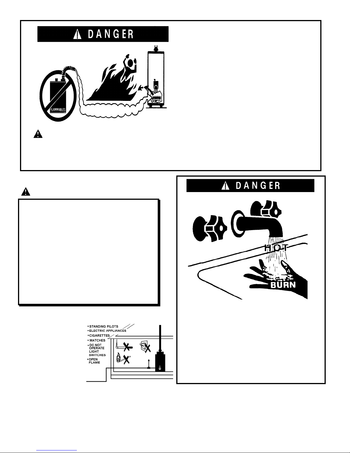
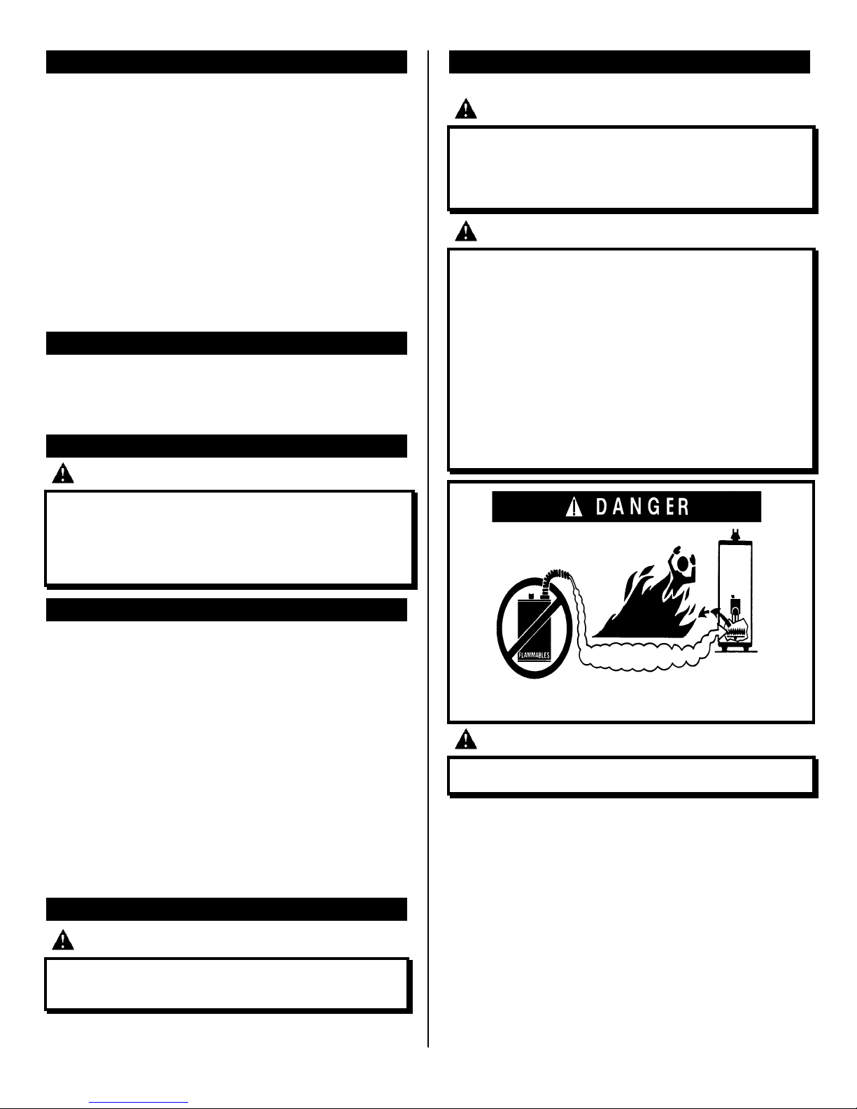
Vapors from flammable liquids will explode
and catch fire causing death or severe burns.
Do not use or store flammable products such as
gasoline, solvents or adhesives in the same room or
area near the water heater.
Keep flammable products:
1. far away from the water heater.
2. in approved containers,
3. tightly closed and
4. out of children’s reach.
Water heater has a main burner and pilot flame. The
pilot flame:
1. is on all the time and
2. will ignite flammable vapors.
Vapors:
1. cannot be seen,
2. are heavier than air
3. go a long way on the floor and
4. can be carried from other rooms to the pilot flame by
air currents.
Do not install this heater where flammable products
will be stored or used unless the main burner and pilot
flames are at least 18 inches above the floor. This will
reduce but not eliminate the risk of vapors being ignited
by the main burner or pilot flame.
DANGER
DO NOT USE THIS WATER HEATER WITH ANY GAS OTHER
THAN THE ONE LISTED ON THE DATA PLATE. This water
heater is equipped for use with one type gas only. Check the
data plate near the gas control valve for the correct gas.
FAILURE TO USE THE CORRECT GAS CAN CAUSE PROBLEMS
WHICH CAN RESULT IN DEATH, SERIOUS BODILY INJURY OR
PROPERTY DAMAGE. If you have any questions or doubts
consult your gas supplier or gas utility company. Water heaters
using bottled propane or liquefied petroleum gas (LPG) are
different from natural gas models. A natural gas water heater
will not function safely on bottled propane or liquefied
petroleum gas (LPG) and a propane gas water heater will not
function safely on natural gas. Do not attempt to convert a
water heater from natural gas to LPG or from LPG to natural
gas.
WHEN REMOVING PURGED GASES FROM A PIPING SYSTEM, DO
NOT CREATE A
HAZARDOUS CONDITION
BY DISCHARGING THE
GASES INTO A CONFINED
AREA OR IN AN AREA THAT
CONTAINS AN IGNITION
SOURCE.
Water temperature over 125°F can cause severe burns
instantly or death from scalds.
Children, disabled and elderly are at highest risk of being
scalded.
See the instruction manual before setting the water
temperature at the water heater.
Feel the water before bathing or showering.
Temperature limiting valves are available for use.
2
GENERAL SAFETY WARNINGS
BEFORE ATTEMPTING TO INSTALL OR OPERATE THIS WATER HEATER, MAKE SURE YOU READ AND UNDERSTAND THE ENTIRE
INSTALLATION, OPERATION AND SERVICE MANUAL. SPECIAL ATTENTION MUST BE GIVEN TO ALL THE SAFETY WARNINGS PROVIDED
THROUGHOUT THIS MANUAL. FAILURE TO FOLLOW THESE WARNINGS COULD RESULT IN A FIRE OR EXPLOSION CAUSING PROPERTY
DAMAGE, PERSONAL INJURY OR DEATH. IF YOU HAVE DIFFICULTY UNDERSTANDING THE INSTRUCTIONS IN THIS MANUAL OR ARE NOT
AN EXPERIENCED INSTALLER, DO NOT PROCEED, BUT GET HELP FROM A QUALIFIED INSTALLATION OR SERVICE TECHNICIAN. FOR ANY
QUESTIONS DURING OR AFTER THE INSTALLATION OF THIS WATER HEATER, CALL 1-800-999-9515.
DANGER
• TAMPERING WITH THE THERMOSTAT, IGNITER CONTROL, GAS
VALVE OR TEMPERATURE AND PRESSURE RELIEF VALVE IS
DANGEROUS AND MAY RESULT IN SERIOUS INJURY OR DEATH.
TAMPERING VOIDS ALL WARRANTIES. ONLY PROPERLY TRAINED,
QUALIFIED SERVICE PERSONNEL SHOULD SERVICE THESE
COMPONENTS. DO NOT ATTEMPT TO MODIFY OR CHANGE THIS
WATER HEATER IN ANY WAY.
• DO NOT ATTEMPT TO CONVERT THIS WATER HEATER FROM
NATURAL GAS TO L.P. OR FROM L.P. TO NATURAL GAS. THIS CAN
RESULT IN PROPERTY DAMAGE, FIRE, EXPLOSION, BODILY HARM OR
DEATH.
• DO NOT INSTALL THIS WATER HEATER IN A MOBILE HOME
• DO NOT INSTALL THIS WATER HEATER OUTDOORS.
• RESIDENTIAL AREAS WHERE FLAMMABLE LIQUIDS (GASOLINE,
SOLVENTS, LIQUID PROPANE, BUTANE, ETC.) OR OTHER SUBSTANCES
WHICH EMIT FLAMMABLE VAPORS ARE STORED MAY NOT BE
SUITABLE FOR WATER HEATER INSTALLATION. NATURAL AIR
MOVEMENTS CAN CARRY FLAMMABLE VAPORS SOME DISTANCE
FROM WHERE THEY ARE STORED OR USED. NEAR GROUND LEVEL
VENTS CAN DRAW THESE VAPORS INTO THE WATER HEATER WHERE
THE PILOT FLAME OR MAIN BURNER CAN IGNITE THEM CAUSING
PROPERTY DAMAGE, SERIOUS BURNS OR DEATH. NEVER STORE OR
USE FLAMMABLE SUBSTANCES IN THE SAME ROOM OR AREA
CONTAINING A GAS WATER HEATER. IF SUCH FLAMMABLES MUST
BE USED, ALL GAS BURNING APPLIANCES IN THE VICINITY MUST BE
SHUT OFF AND THEIR PILOT LIGHTS EXTINGUISHED. OPEN THE
DOORS AND WINDOWS FOR VENTILATION WHILE FLAMMABLE
SUBSTANCES ARE IN USE.
• FLAMMABLE VAPORS MAY BE DRAWN TO THIS WATER HEATER
FROM OTHER AREAS OF THE STRUCTURE BY AIR CURRENTS.
• WATER HEATERS INSTALLED IN RESIDENTIAL GARAGES MUST BE
INSTALLED SUCH THAT THE PILOT FLAME AND MAIN BURNER
FLAME ARE NO LESS THAN 18 INCHES ABOVE THE FLOOR. THIS IS
TO REDUCE BUT NOT ELIMINATE THE RISK OF IGNITING FLAMMABLE
VAPORS WHICH MAY BE PRESENT IN A GARAGE. THIS WATER
HEATER MUST BE LOCATED OR PROTECTED TO AVOID PHYSICAL
DAMAGE BY VEHICLES OR FLOODING.
• THE WATER HEATER IS CERTIFIED FOR INSTALLATION ON A
COMBUSTIBLE FLOOR. HOWEVER WHEN THIS WATER HEATER IS
INSTALLED OVER CARPETING, THE CARPETING MUST BE PROTECTED
BY A METAL OR WOOD PANEL BENEATH THE WATER HEATER AND
EXTENDING BEYOND THE FULL WIDTH AND DEPTH OF THE WATER
HEATER BY AT LEAST THREE INCHES IN ANY DIRECTION. IF THE
WATER HEATER IS INSTALLED IN A CARPETED ALCOVE OR CLOSET,
THE ENTIRE FLOOR MUST BE COVERED BY THE PANEL. FAILURE TO
FOLLOW THESE INSTRUCTIONS MAY RESULT IN A FIRE HAZARD.
• THIS WATER HEATER AND ANY OTHER GAS FUEL BURNING
APPLIANCE MUST BE PROVIDED WITH ENOUGH FRESH AIR FOR
PROPER VENTILATION OF THE FLUE GASES.
• VENTILATION AND COMBUSTION AIR SUPPLIES CANNOT BE TAKEN
FROM AREAS THAT CONTAIN NEGATIVE PRESSURE PRODUCING
DEVICES SUCH AS FIREPLACES, EXHAUST FANS AND AIR
CIRCULATION SYSTEMS. INLET AIR CANNOT BE TAKEN FROM AN
ATTIC EQUIPPED WITH POWER VENTILATION.
• PROPER VENT PIPE INSTALLATION IS CRITICAL TO THE SAFE
OPERATION OF THIS WATER HEATER. FAILURE TO PROPERLY VENT
THIS WATER HEATER CAN CAUSE AN EXPLOSION, FIRE, OR CARBON
MONOXIDE POISONING WHICH CAN RESULT IN PROPERTY DAMAGE,
PERSONAL INJURY OR DEATH.
• CONNECTION OF THE VENT PIPE TO THE OUTLET OF THE VENT
ASSEMBLY BLOWER MUST BE PROPERLY SEALED TO PREVENT
LEAKAGE OF THE PRODUCTS OF COMBUSTION INTO THE LIVING
SPACE.
• OBSTRUCTIONS OR HOLES IN THE VENT PIPE CAN CAUSE TOXIC
FUMES TO ENTER THE HOME RESULTING IN CARBON MONOXIDE
POISONING OR DEATH. THE VENT PIPE MUST BE REPLACED IF IT IS
LEAKING.
• NEVER OPERATE AN EMPTY OR PARTIALLY FILLED WATER HEATER.
THIS CAN RESULT IN SERIOUS DAMAGE TO THE TANK.
• DO NOT ATTEMPT TO OPERATE THIS WATER HEATER WITH THE
COLD WATER SHUTOFF VALVE CLOSED.
• DO NOT ATTEMPT TO OPERATE THIS WATER HEATER WITHOUT A
PROPERLY INSTALLED TEMPERATURE AND PRESSURE RELIEF VALVE.
FAILURE TO INSTALL AND MAINTAIN A NEW AND PROPERLY LISTED
TEMPERATURE AND PRESSURE RELIEF VALVE WILL RELEASE THE
MANUFACTURER FROM ANY CLAIMS WHICH MIGHT RESULT FROM
EXCESSIVE TEMPERATURE OR WATER PRESSURE.
• WATER SUPPLY TO THIS HEATER MUST NOT EXCEED 180° F. WATER
TEMPERATURES IN EXCESS OF 180° F WILL CAUSE THE HIGH LIMIT
CONTROL (ECO) TO OPEN AND SHUT OFF THE GAS SUPPLY TO THE
UNIT. THE HIGH LIMIT CONTROL IS A SINGLE USE TYPE THAT WILL
REQUIRE THE REPLACEMENT OF THE THERMOSTAT BEFORE THE
BURNER CAN OPERATE.
• THIS WATER HEATER IS EQUIPPED FOR ONE TYPE OF GAS ONLY. DO
NOT USE THIS WATER HEATER WITH ANY GAS OTHER THAN THE
ONE LISTED ON THE DATA PLATE LOCATED NEAR THE GAS
CONTROL. FAILURE TO USE THE CORRECT GAS CAN RESULT IN
PROPERTY DAMAGE, BODILY INJURY OR DEATH.
• CONTAMINANTS IN THE GAS PIPING MAY FOUL THE GAS CONTROL /
THERMOSTAT CAUSING A MALFUNCTION, FIRE OR EXPLOSION. BE
SURE ALL GAS PIPING IS CLEAN AND CLEAR ON THE INSIDE BEFORE
ATTACHING THE GAS LINE.
• DO NOT USE AN OPEN FLAME OR ANY KIND OF SPARK TO CHECK
GAS PIPING FOR LEAKS.
3
GENERAL SAFETY WARNINGS
DANGER
• THE GAS LINE MUST BE OF ADEQUATE SIZE SO AS TO PREVENT
UNDUE PRESSURE DROP AND NEVER SMALLER THAN THE PIPE SIZE
TO THE GAS VALVE ON THE WATER HEATER. FAILURE TO PROPERLY
SIZE THE GAS LINE CAN RESULT IN A FIRE OR EXPLOSION CAUSING
PROPERTY DAMAGE, PERSONAL INJURY OR DEATH.
• DO NOT ATTEMPT TO LIGHT THIS WATER HEATER UNTIL IT IS
PROPERLY INSTALLED AND YOU UNDERSTAND ALL OF THE SAFETY
WARNINGS AND PRECAUTIONS.
• ADJUSTING THE THERMOSTAT PAST THE 120° F BAR ON THE
TEMPERATURE DIAL WILL INCREASE THE RISK OF SCALD INJURY.
SEE SECTION "WATER TEMPERATURE REGULATION".
• HOUSEHOLDS WITH SMALL CHILDREN, ELDERLY, IMPAIRED OR
DISABLED MEMBERS AND ANYONE WITH TEMPERATURE
SENSITIVE SKIN MAY REQUIRE A LOW TEMPERATURE SETTING TO
REDUCE THE RISK OF SCALD INJURY.
• HOT WATER CAN PRODUCE FIRST DEGREE BURNS WITHIN:
3 SECONDS AT 140°F (60°C)
20 SECONDS AT 130°F (54°C)
8 MINUTES AT 120°F (49°C)
• DO NOT ATTEMPT TO BYPASS OR JUMPER THE ECO. THIS WILL
VOID THE WARRANTY AND RELEASE THE MANUFACTURER FROM
ANY LIABILITY FOR ANY ACCIDENT RESULTING FROM ELIMINATING
THE ECO FROM THE WATER HEATER CIRCUIT.
• HYDROGEN GAS CAN BE PRODUCED IN A HOT WATER SYSTEM
THAT HAS NOT BEEN USED FOR A LONG PERIOD OF TIME
(GENERALLY TWO WEEKS OR MORE). HYDROGEN GAS IS
EXTREMELY FLAMMABLE AND CAN IGNITE WHEN EXPOSED TO A
SPARK OR FLAME. TO PREVENT THE POSSIBILITY OF INJURY
UNDER THESE CONDITIONS, WE RECOMMEND THE HOT WATER
FAUCET BE OPENED FOR SEVERAL MINUTES AT THE KITCHEN SINK
BEFORE USING ANY ELECTRICAL APPLIANCE WHICH IS CONNECTED
TO THE HOT WATER SYSTEM. IF HYDROGEN IS PRESENT, THERE
WILL PROBABLY BE AN UNUSUAL SOUND SUCH AS AIR ESCAPING
THROUGH THE FAUCET AS WATER BEGINS TO FLOW. DO NOT
SMOKE OR HAVE ANY OPEN FLAME NEAR THE FAUCET AT THE TIME
IT IS OPEN.
• REPAIR, REPLACEMENT, SERVICE AND CLEANING OF WATER
HEATER PARTS MUST ONLY BE PERFORMED BY A QUALIFIED
SERVICE TECHNICIAN
.
TABLE OF CONTENTS
PAGE
SAFETY PRECAUTIONS ..................................................... 1,2
GENERAL SAFETY WARNINGS ....................................................... 3,4
CONSUMER INFORMATION/RESPONSIBILITIES ............................ 4
TABLE OF CONTENTS ........................................................................... 4
WATER HEATER
MODIFICATION/TAMPERING
LOCATION REQUIREMENTS AND CONSIDERATIONS .................... 5,6
VENTILATION AND COMBUSTION AIR SUPPLY ............................ 7,8
VENT PIPE SYSTEM ..................................................................... 9,10
WATER SYSTEM PIPING ................................................................. 11,12
SPECIAL APPLICATIONS ................................................................. 13
GAS SUPPLY AND PIPING ............................................................. 14,15
ELECTRICAL CONNECTIONS .............................................................. 15,16
INSTALLATION CHECK LIST ........................................................... 16
START-UP/OPERATION ................................................................. 17-19
OPERATIONAL CONDITIONS ........................................................... 20,21
MAINTENANCE .............................................................................. 21,22
BURNER ASSEMBLY REMOVAL, CLEANING, AND REPLACEMENT ... 22
GAS CONTROL VALVE/THERMOSTAT REPLACEMENT 23
THERMOCOUPLE AND PILOT ASSY. REPLACEMENT ..................... 23
TROUBLESHOOTING GUIDE .................................... 24,25
REPAIR PARTS LIST AND ILLUSTRATION ................................... 26,27
IMPORTANT: TO INSURE PROPER INSTALLATION AND OPERATION OF THIS PRODUCT, COMPLETELY READ ALL
INSTRUCTIONS PRIOR TO ATTEMPTING TO ASSEMBLE, INSTALL, OPERATE, MAINTAIN OR REPAIR THIS PRODUCT. UPON
UNPACKING OF THE WATER HEATER, INSPECT ALL PARTS FOR DAMAGE PRIOR TO INSTALLATION AND START-UP.
..................................... 5
This water heater is design-certified by CSA International as a Category IV, nondirect vented water heater which takes its combustion air either from the
installation area or from air ducted to the unit from the outside.
This water heater should be installed in accordance with the latest edition of the
“National Fuel Gas Code”, ANSI Z223.1, NFPA 54 and the requirements and codes
of the local utilities or other authorities having jurisdiction. This is available from
the following:
4
CONSUMER INFORMATION
National Fire Protection Agency
1 Batterymarch Park
Quincy, MA 02269
Local Authorities (Check your telephone listings.)
American Gas Association
1515 Wilson Boulevard
Arlington, VA 22209
CONSUMER RESPONSIBILITIES
This manual has been prepared to acquaint you with the installation, operation and
maintenance of your gas water heater and to provide important safety information
in these areas.
We urge you to read all of the instructions thoroughly before attempting the
installation or operation of this water heater. This manual should be kept for
future reference.
The manufacturer of this water heater will not be liable for any damages caused
by failure to comply with the in-stallation and operating instructions outlined in
this manual.
If you lack the necessary skills required to properly install this water heater or you
have difficulty following the directions, you should not proceed but have a
qualified person perform the installation of this water heater.
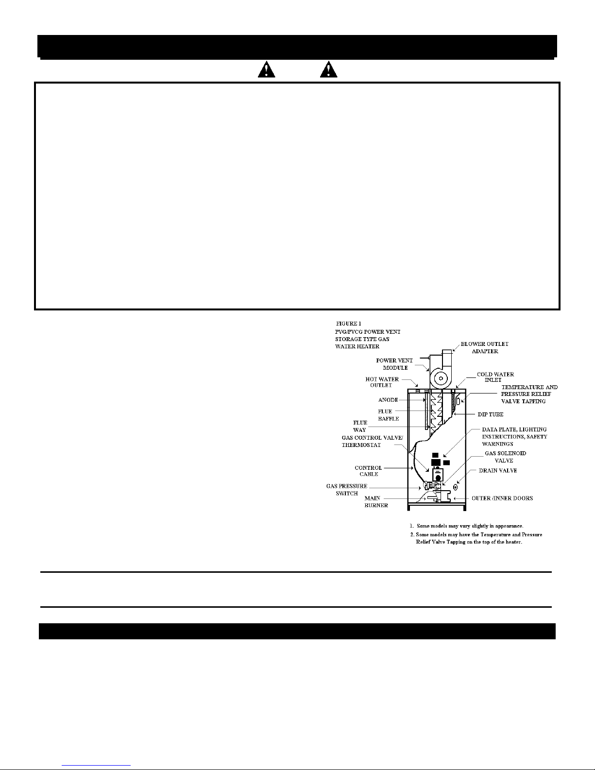
A data plate identifying your water heater can be found next to the gas control
valve/thermostat. When referring to your water heater always have the
information listed on the data plate readily available.
Retain your original receipt as proof of purchase.
HIGH ALTITUDE INPUT RATING
The input rating on the data plate of this water heater is for installations up to
2000 feet of elevation. For installations at elevations above 2000 feet, the rating
should be reduced by 4 percent for each 1000 feet above sea level. For correct
orifice at altitudes above 2000 feet: consult the National Fuel Gas Code, your
local utility or water heater supplier.
WATER HEATER MODIFICATION/ TAMPERING
DANGER
TAMPERING WITH THE THERMOSTAT, IGNITER CONTROL, GAS VALVE, OR
TEMPERATURE AND PRESSURE RELIEF VALVE IS DANGEROUS AND MAY
RESULT IN SERIOUS INJURY OR DEATH. TAMPERING VOIDS ALL
WARRANTIES. ONLY PROPERLY TRAINED, QUALIFIED SERVICE
PERSONNEL SHOULD SERVICE THESE COMPONENTS. DO NOT ATTEMPT
TO MODIFY OR CHANGE THIS WATER HEATER IN ANY WAY.
LOCATION REQUIREMENTS AND CONSIDERATIONS
GENERAL INFORMATION
WARNING
DO NOT INSTALL THIS WATER HEATER IN A MOBILE HOME. This water
heater is not approved for installation in a mobile home. DO NOT INSTALL
OUTDOORS. This water heater is certified for indoor installation only. Failure to
follow these instructions could result in FIRE, PROPERTY DAMAGE, PERSONAL
INJURY OR DEATH.
DANGER
AREAS WHERE FLAMMABLE LIQUIDS (GASOLINE, SOLVENTS, LIQUID
PROPANE, BUTANE, ETC.) OR OTHER SUBSTANCES WHICH EMIT
FLAMMABLE VAPORS ARE STORED MAY NOT BE SUITABLE FOR WATER
HEATER INSTALLATION. NATURAL AIR MOVEMENTS CAN CARRY
FLAMMABLE VAPORS SOME DISTANCE FROM WHERE THEY ARE STORED
OR USED. NEAR GROUND LEVEL VENTS CAN DRAW THESE VAPORS INTO
THE WATER HEATER WHERE THE PILOT FLAME OR MAIN BURNER CAN
IGNITE THEM CAUSING PROPERTY DAMAGE, SERIOUS BURNS OR DEATH.
NEVER STORE OR USE FLAMMABLE SUBSTANCES IN THE SAME ROOM OR
AREA CONTAINING A GAS WATER HEATER. IF SUCH FLAMMABLES MUST
BE USED, ALL GAS BURNING APPLIANCES IN THE VICINITY MUST BE
SHUT OFF AND THEIR PILOT LIGHTS EXTINGUISHED. OPEN THE DOORS
AND WINDOWS FOR VENTILATION WHILE FLAMMABLE SUBSTANCES ARE
IN USE.
INSULATION BLANKET
Some governing bodies may require the use of external insulation blankets when
water heaters are installed in newly constructed homes and additions. If an
insulation blanket is applied to this water heater CAUTION must be exercised so
as to not restrict its proper function and operation. Please note the following:
• The space between the base of the water heater and the floor must remain
unobstructed to allow for proper air flow. As time passes, the blanket may
sag and obstruct the air passage resulting in unsafe water heater operation.
• Do not apply an insulation blanket to the top of the water heater as this may
obstruct the draft hood.
• Do not cover the temperature and pressure relief valve or any labels or
instruction materials applied to the water heater. These labels must remain
visible for reference by the user. Do not remove these labels as they are a
permanent part of the water heater as required by the certification agencies
and/or the Federal Government.
• Do not cover any access panels leading to burner compartments. Do not
cover the thermostat controls, doors, or the temperature and pressure relief
valve on the water heater.
GAS CONVERSION
DANGER
DO NOT ATTEMPT TO CONVERT THIS WATER HEATER FROM NATURAL
GAS TO L.P. OR FROM L.P. TO NATURAL GAS. THIS CAN RESULT IN
PROPERTY DAMAGE, FIRE, EXPLOSION, BODILY HARM OR DEATH.
VAPORS FROM FLAMMABLE LIQUIDS WILL EXPLODE AND CATCH FIRE
CAUSING DEATH OR SEVERE BURNS.
WARNING
FLAMMABLE VAPORS MAY BE DRAWN TO THIS WATER HEATER FROM
OTHER AREAS OF THE STRUCTURE BY AIR CURRENTS.
IMPORTANT: This water heater should not be installed near a corrosive or
potentially corrosive air supply. Water heater corrosion and component failure can
be caused by the heating and breaking down of airborne chemicals. These
materials are corrosive at low concentration levels with little or no odor to reveal
their presence. Examples of potentially corrosive locations and compounds are:
• Beauty shops, dry cleaning establishments, photo processing labs
• Liquid or powdered bleaches, swimming pool chemicals, spray can
propellants, cleaning solvents
• Refrigerants
• Calcium and sodium chloride
• Waxes and process chemicals
• Products of this sort should not be stored near the water heater or air inlet.
5
LOCATION REQUIREMENTS AND CONSIDERATIONS
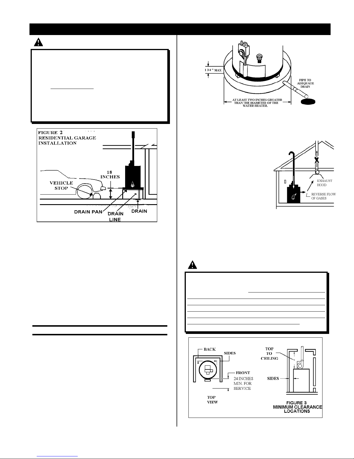
WARNING
IT IS NOT DESIRABLE TO INSTALL A GAS FIRED WATER HEATER IN A
RESIDENTIAL GARAGE. IF INSTALLATION IN A RESIDENTIAL GARAGE IS
YOUR ONLY OPTION, THIS WATER HEATER MUST BE INSTALLED SUCH
THAT THE PILOT FLAME AND MAIN BURNER FLAME ARE NO LESS THAN
18 INCHES ABOVE THE FLOOR (SEE FIGURE 2 BELOW). THIS IS TO
REDUCE BUT NOT ELIMINATE THE RISK OF IGNITING FLAMMABLE
VAPORS WHICH MAY BE PRESENT IN A GARAGE. THE WATER HEATER
MUST BE LOCATED OR PROTECTED TO AVOID PHYSICAL DAMAGE
BY VEHICLES OR FLOODING. FAILURE TO FOLLOW THESE
WARNINGS CAN CAUSE A FIRE OR EXPLOSION, RESULTING IN
PROPERTY DAMAGE, PERSONAL INJURY OR DEATH.
SITE LOCATION
1. Select a location near the center of the water piping system. It must
be installed indoors and in a vertical position on a level surface. DO
NOT install in bathrooms, bedrooms or any occupied room normally
kept closed.
2. Locate the water heater as close to the chimney or gas vent as is
practical. Consider the vent system piping and combustion air supply
requirements when selecting the water heater location. The venting
system must be able to run from the water heater to the termination
with a minimal length and elbows. THE VENT PIPE CANNOT
EXCEED THE MAXIMUM ALLOWABLE LENGTH OF 40 FEET WITH
3 LONG RADIUS ELLS.
3. Locate the water heater near the existing gas piping. If installing a new
gas line, locate the water heater to minimize the pipe length and
elbows.
IMPORTANT
4. The water heater should be located in an area where leakage of the
tank or connections will not result in damage to the area adjacent to
the water heater or to lower floors of the structure. It is recommended
that a suitable drain pan be installed under the water heater as shown
above. This pan is to protect the property from damage which may
occur from normal condensate formation on the tank jacket or leaks in
the tank and pipe connections. The pan must limit the water level to a
maximum depth of 1 3/4 inches and be two inches wider than the
heater and piped to an adequate drain. Locate the water heater near a
suitable inside drain. Outside drains are subject to freezing
temperatures. The piping should be at least 3/4” ID and pitched for
proper drainage. This pan must not restrict combustion air flow.
UNDER NO CIRCUMSTANCES IS THE MANUFACTURER TO BE
HELD LIABLE FOR ANY WATER DAMAGE IN CONNECTION WITH
THIS WATER HEATER.
6
5. The water heater should be located in an area not subject to freezing
temperatures. Water heaters located in unconditioned areas (i.e. attics,
basements, etc.) may require the insulation of the water piping and drain
piping to protect against freezing. The drain and controls must be easily
accessible for operation and service.
Maintain proper clearances as specified.
6. Do not locate the water heater near an air-
moving device. The operation of air-moving
devices such as exhaust fans, ventilation
systems, clothes dryers, fireplaces, etc.,
can affect the proper operation of the
water heater. Special attention must be
given to conditions these devices may
create to avoid unsatisfactory operation
of the equipment.
CLEARANCE/ACCESSIBILITY
Minimum clearances from combustible materials are stated on the data plate
adjacent to the thermostat of the water heater. REFER TO THE DATA
PLATE OF THE WATER HEATER FOR THE CORRECT CLEARANCES
FROM COMBUSTIBLE CONSTRUCTION MATERIALS. Figure 3 may be
used as a reference guide to locate the specific clearance locations. A
minimum of 24 inches of front clearance should be provided for inspection and
service.
WARNING
THE WATER HEATER IS CERTIFIED FOR INSTALLATION ON A
COMBUSTIBLE FLOOR. HOWEVER, WHEN THIS WATER HEATER IS
INSTALLED OVER CARPETING, THE CARPETING MUST BE PROTECTED
BY A METAL OR WOOD PANEL BENEATH THE WATER HEATER AND
EXTENDING BEYOND THE FULL WIDTH AND DEPTH OF THE WATER
HEATER BY AT LEAST THREE INCHES IN ANY DIRECTION. IF THE
WATER HEATER IS INSTALLED IN A CARPETED ALCOVE OR CLOSET,
THE ENTIRE FLOOR MUST BE COVERED BY THE PANEL. FAILURE TO
FOLLOW THESE INSTRUCTIONS MAY RESULT IN A FIRE HAZARD.
VENTILATION AND COMBUSTION AIR SUPPLY
GENERAL INFORMATION
WARNING
THIS WATER HEATER AND ANY OTHER FUEL BURNING APPLIANCE
MUST BE PROVIDED WITH ENOUGH FRESH AIR FOR PROPER
VENTILATION OF THE FLUE GASES. MOST HOMES WILL REQUIRE
THAT OUTSIDE AIR BE SUPPLIED INTO THE WATER HEATER AREA.
FAILURE TO DO SO CAN RESULT IN EXPLOSION, FIRE, PROPERTY
DAMAGE, CARBON MONOXIDE POISONING, PERSONAL INJURY OR
DEATH.
Adequate facilities for providing air for combustion and ventilation must be
provided in accordance with the “National Fuel Gas Code”, ANSI Z223.1Latest Edition, NFPA 54 or the applicable provisions of the local building
codes.
IMPORTANT: Air for combustion and ventilation must not come from a
corrosive atmosphere. Any failure due to corrosive elements in the
atmosphere is excluded from warranty coverage.
The following types of installation (but not limited to the following) will
require outdoor air for combustion due to chemical exposure and may
reduce but not eliminate the presence of corrosive chemicals in the air:
• Beauty shops
• Photo processing labs
• Commercial buildings
• Buildings with indoor pools
• Water heaters installed in laundry, hobby or craft rooms.
• Water heaters installed near chemical storage areas
Combustion air must be free of acid-forming chemicals such as sulfur,
fluorine, and chlorine. These elements are found in aerosol sprays,
detergents, bleaches, cleaning solvents, air fresheners, paint and varnish
removers, refrigerants, and many other commercial and household
products. When burned, vapors from these products form highly corrosive
acid compounds. These products should not be stored near the water
heater or air inlet.
Combustion and ventilation air requirements are de-termined by the location
of the water heater. The water heater may be located in either an open
(unconfined) area or in a confined area or small enclosure such as a closet
or small room. Confined spaces are areas with less than 50 cubic feet
for each 1,000 BTUH of the total input for all gas-using appliances.
WATER HEATER LOCATION - UNCONFINED SPACE
A water heater in an unconfined space uses indoor air for combustion and
requires at least 50 cubic feet for each 1,000 BTUH of the total input
for all gas appliances. The table below shows a few examples of the
minimum square feet required for various BTUH inputs.
BTUH
INPUT
30,000 188 9 X 21
45,000 281 14 X 20
60,000 375 15 X 25
75,000 469 15 X 31
90,000 563 20 X 28
105,000 657 20 X 33
120,000 750 25 X 30
135,000 844 28 X 30
Areas which are being used for storage or contain large space consuming
items may not be suitable for water heater installation. The area must be
open and be able to provide the proper air requirements to the water
heater.
MIN. SQ. FEET
WITH 8’ CEILING
TYPICAL ROOM SIZE
WITH 8’ CEILING
IMPORTANT: Water heaters installed in open spaces in buildings with
unusually tight construction may still require outdoor air to function
properly. In this situation, outside air openings should be sized the same as
for a confined space.
MODERN CONSTRUCTION USUALLY REQUIRES SUPPLYING OUTSIDE AIR
INTO THE WATER HEATER AREA.
CONSULT THE LOCAL CODES OF YOUR AREA FOR SPECIFIC
VENTILATION AND COMBUSTION AIR REQUIREMENTS.
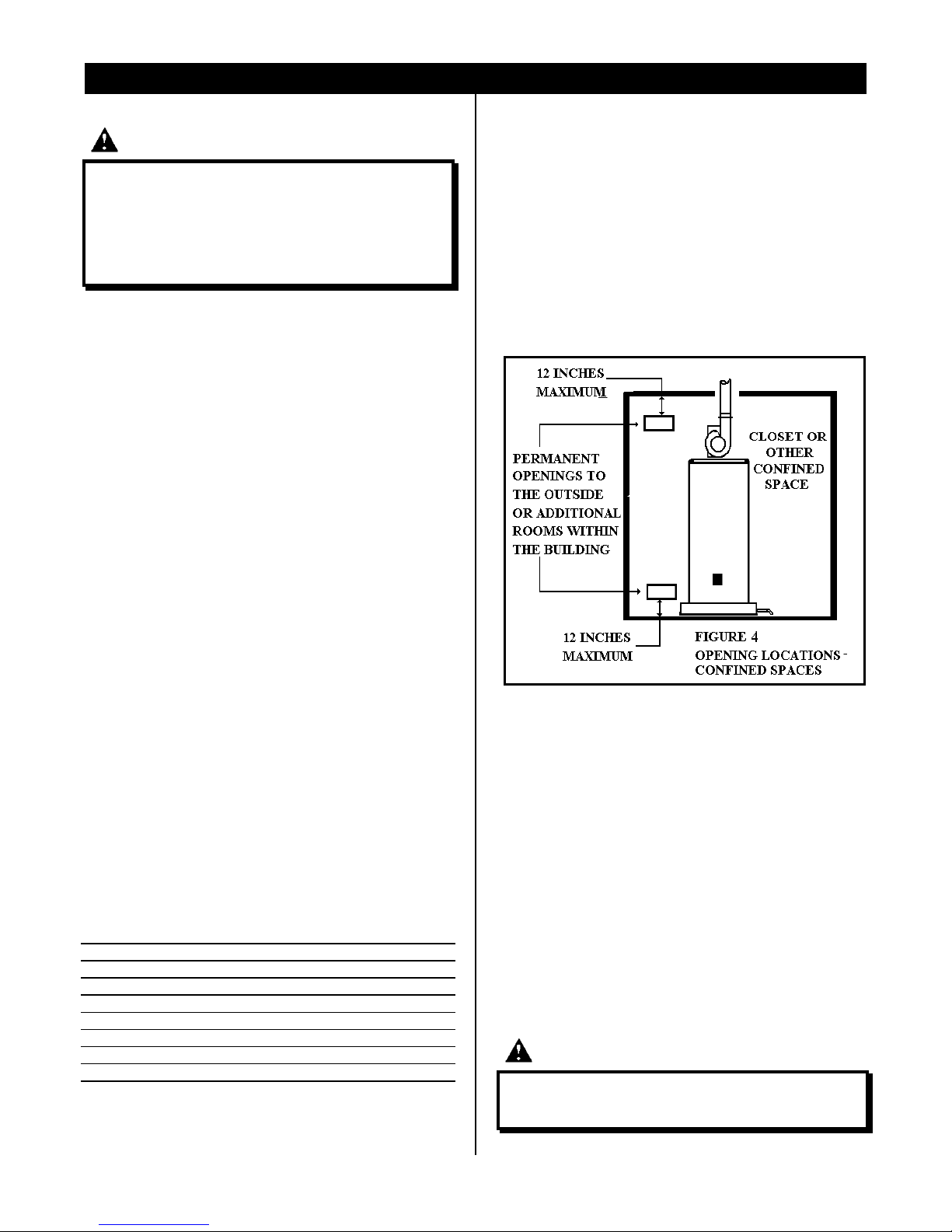
For the correct and safe operation of this water heater, ample air must be
supplied for the combustion, ventilation and dilution of flue gases. Small
enclosures and confined areas must have two permanent openings so
that sufficient fresh air can be drawn from outside of the enclosure. One
opening shall be within 12 inches of the top and one within 12 inches
of the bottom of the enclosure as shown in Figure 4 below.
The size of each opening (free area) is determined by the total Btuh input of
all gas utilization equipment (i.e. water heaters, furnaces, clothes dryers,
etc.) and the method by which the air is provided. The Btuh input can be
found on the water heater data plate. Additional air can be provided by two
methods:
1. All air from inside the building.
2. All air from outdoors.
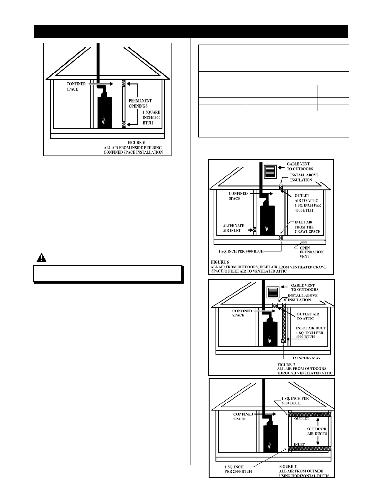
ALL AIR FROM INSIDE THE BUILDING
When additional air is to be provided to the confined area from additional
room(s) within the building, the total volume of the room(s) must be of
sufficient size to properly provide the necessary amount of fresh air to the
water heater and other gas utilization equipment in the area. If you are
unsure that the structure meets this requirement, contact your local gas
utility company or other qualified agency for a safety inspection.
Each of the two openings shall have a minimum free area of 1 square inch
per 1,000 Btuh of the total input rating of all gas utilization equipment in
the confined area, but not less than 100 square inches (Figure 5).
CAUTION
AIR CANNOT BE TAKEN FROM AREAS THAT CONTAIN NEGATIVE
PRESSURE PRODUCING DEVICES SUCH AS FIREPLACES, EXHAUST
FANS, AND AIR CIRCULATION SYSTEMS.
7
VENTILATION AND COMBUSTION AIR SUPPLY (CONT.)
ALL AIR FROM OUTDOORS
Outdoor fresh air can be provided to a confined area either directly or by
the use of vertical and horizontal ducts. The fresh air can be taken from the
outdoors or from crawl or attic spaces that freely communicate with the
outdoors. Attic or crawl spaces cannot be closed and must be properly
ventilated to the outside.
Ductwork must be of the same cross-sectional area as the free area of the
opening to which they connect. The minimum dimension of rectangular air
ducts cannot be less than 3 inches.
The size of each of the two openings is determined by the method in which
the air is to be provided. Refer to Table 1 to calculate the minimum free
area for each opening. Figures 6, 7, and 8 are typical examples of each
method.
TABLE 1
MINIMUM FREE AREA OF PERMANENT OPENINGS FOR
VENTILATION AND COMBUSTION AIR SUPPLY - ALL AIR
FROM OUTSIDE ONLY.
OPENING SOURCE MINIMUM FREE AREA PER
OPENING (SQ. IN.)
DIRECT TO
OUTDOORS*
VERTICAL DUCTS
HORIZONTAL DUCTS 1 SQUARE INCH PER 2000 BTUH
Example: A water heater with an input rate of 50,000 Btuh using horizontal
ducts would require each opening to have a minimum free area of 25 square
inches.
Minimum Free Area = 50,000 Btuh x 1 sq. in. / 2000 Btuh = 25 Sq Inches
* These openings may communicate directly with the outdoors through a
ventilated attic, a ventilated crawl space, or through an outside wall.
1 SQUARE INCH PER 4000 BTUH FIGURE 6
1 SQUARE INCH PER 4000 BTUH FIGURE 7
REFERENCE
DRAWING
FIGURE 8
CAUTION
INLET AIR CANNOT BE TAKEN FROM AN ATTIC EQUIPPED WITH
POWER VENTILATION.
LOUVERS AND GRILLES
In calculating free area for ventilation and combustion air supply openings,
consideration must be given to the blocking affect of protection louvers,
grilles, and screens. These devices can reduce air flow which in turn may
require larger openings to achieve the required minimum free area. Screens
must not be smaller than 1/4 inch mesh. If the free area through a
particular design of louver or grille is known, it should be used in
calculating the specified free area of the opening. If the design and free
area are not known, it can be assumed that most wood louvers will allow
20 - 25% of free area while metal louvers and grilles will allow 60 - 75% of
free area. Louvers and grilles must be locked open or interconnected with
the equipment so that they are opened automatically during equipment
operation.
Keep louvers and grilles clean and free of debris or other obstructions.
8
VENT PIPING SYSTEM
GENERAL INFORMATION
DANGER
PROPER VENT PIPE INSTALLATION IS CRITICAL TO THE SAFE
OPERATION OF THIS WATER HEATER. FAILURE TO PROPERLY VENT
THIS WATER HEATER CAN CAUSE AN EXPLOSION, FIRE OR CARBON
MONOXIDE POISONING WHICH CAN RESULT IN PROPERTY DAMAGE,
PERSONAL INJURY, OR DEATH.
This water heater has been certified by CSA International for use with the
specified plastic pipe material.
This vent pipe system must be installed in accordance with the “National Fuel
and Gas Code”, NFPA 54, ANSI Z223.1 - Latest Edition.
The National Fuel and Gas Code allows the use of plastic pipe for venting if it is
accepted by the local code or the authority having jurisdiction.
Some local jurisdictions may be opposed to plastic vent pipe. Check with your
local code official before installing this system.
Use only 3 inch Schedule 40 PVC, ABS-DWP, or CPVC plastic pipe and fittings
for this vent pipe system. All fittings must be Long Sweep. DO NOT USE SHORT
RADIUS OR MEDIUM SWEEP FITTINGS. THE USE OF SHORT RADIUS
FITTINGS WILL CAUSE THIS WATER HEATER TO MALFUNCTION OR
NUISANCE TRIP ON THE PRESSURE SWITCH CAUSING THE BURNER TO
NOT OPERATE PROPERLY.
Pipe and fittings are available from your water heater dealer or through most
plumbing supply houses.
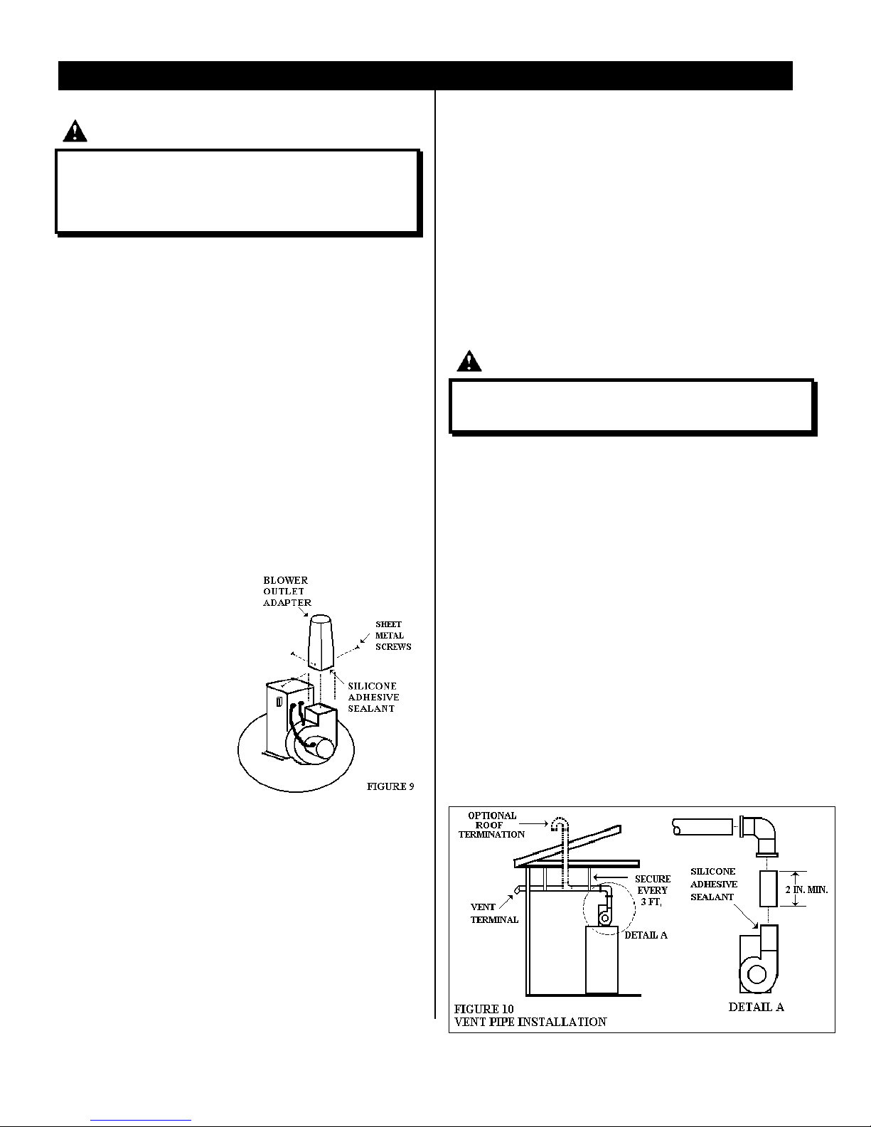
BLOWER OUTLET ADAPTER
The blower outlet adapter must be secured to the outlet of the power vent
blower opening using silicone
adhesive sealant and sheet metal
screws as shown in Figure 9.
1. Apply an even 1/8 inch bead of
silicone adhesive sealant
around the inside of the
adapter’s square opening.
Locate this bead 1/4 inch from
the top of the opening.
1. Slide the adapter approximately
1/2 inch onto the blower
opening and secure with two
sheet metal screws.
IMPORTANT: This connection must
be properly sealed to prevent the leakage of the products of combustion into the
living area. Excess silicone adhesive inside the adapter can cause enough
restriction in the vent pipe to cause intermittent burner operation.
• Vent diameter must not be reduced.
• Support all fittings and pipe runs with proper pipe hold-down hardware at
least every three feet.
• Do not use damaged pipe or fittings.
• All joints must be properly cemented.
• Vent piping installed in unconditioned spaces must be properly insulated
• Make sure the inside of the pipe is clean and free of cuttings and loose dirt.
• Size and cut all piping before cementing. Make clean, square cuts.
• Do not connect this venting system with an existing vent or chimney.
• Do not common vent with the vent pipe of any other water heater or
appliance.
• Do not run plastic vent pipe through a fire break wall.
• Do not screw, nail, rivet or make any holes in the vent pipe or fittings.
• Do not turn on the water heater until the adhesive has completely cured.
DANGER
CONNECTION OF THE VENT PIPE TO THE OUTLET OF THE VENT
ASSEMBLY BLOWER MUST BE PROPERLY SEALED TO PREVENT
LEAKAGE OF THE PRODUCTS OF COMBUSTION INTO THE LIVING SPACE.
IMPORTANT: Fittings such as elbows and couplings must not be attached
directly to the blower outlet. A short length of vent pipe (2 inches minimum)
must be used to connect an elbow or coupling to the blower outlet as shown
in Figure 10.
Use silicone adhesive sealant to secure the vent pipe to the blower outlet. Use
a good grade of pipe cement to secure the vent pipe and fittings to each
other.
For PVC, CPVC, and ABS pipe:
1. Cut the pipe ends square, remove the ragged edges and burrs.
2. Chamfer the pipe end, apply a primer to the fitting and pipe.
3. Apply an even coat of a good grade of pipe cement inside the fitting.
Apply a liberal amount of cement to the outside of the pipe to socket
depth.
4. Assemble the parts quickly while the cement is still wet. Twist the pipe 1/4
turn during insertion and hold together for 30 seconds.
5. Wipe off the excess cement and do not handle for 15 minutes. Cure time
will vary according to temperature, humidity, and fit.
VENT PIPE INSTALLATION
When installing this vent pipe system, please note the following:
• Use only Schedule 40 PVC, CPVC, or ABS-DWV plastic pipe and fittings.
• Maximum vent pipe length is 40 feet with three 90 degree long sweep
elbows.
• The minimum clearance from plastic vent pipe to combustible materials is 0
(zero) inches.
• Venting should be as direct as possible with a minimum pipe length and
fittings.
9
 Loading...