


Assembly and operating instructions
REMKO RKL 300, RKL 300 S-Line, RKL 360, RKL 360 S-Line
Local Air Conditioner
0058-2014-01 Edition 2, en_GB
Read the instructions prior to performing any task!

Read these operating instructions carefully before commissioning / using this device!
These instructions are an integral part of the system and must
always be kept near or on the device.
Subject to modifications; No liability accepted for errors or misprints!
Installation and operating instructions (translation of the original)

Table of contents
1 Safety and usage instructions............................................................................................................. 4
1.1 General safety notes....................................................................................................................... 4
1.2 Identification of notes...................................................................................................................... 4
1.3 Personnel qualifications.................................................................................................................. 4
1.4 Dangers of failure to observe the safety notes................................................................................ 4
1.5 Safety-conscious working............................................................................................................... 4
1.6 Safety notes for the operator........................................................................................................... 5
1.7 Safety notes for installation, maintenance and inspection.............................................................. 5
1.8 Unauthorised modification and changes......................................................................................... 5
1.9 Intended use................................................................................................................................... 5
1.10 Warranty........................................................................................................................................ 5
1.11 Transport and packaging.............................................................................................................. 6
1.12 Environmental protection and recycling........................................................................................ 6
2 Technical data....................................................................................................................................... 7
2.1 Unit data.......................................................................................................................................... 7
3 Design and function.............................................................................................................................. 8
4
Operation............................................................................................................................................... 9
5 Assembly and installation.................................................................................................................. 12
6 Electrical wiring................................................................................................................................... 15
7 Commissioning................................................................................................................................... 16
8 Troubleshooting and customer service............................................................................................ 17
9 Care and maintenance........................................................................................................................ 18
10 Shutdown............................................................................................................................................. 19
11 Exploded view and spare parts lists................................................................................................. 20
11.1 Exploded view of the unit ........................................................................................................... 20
11.2 Spare parts list ........................................................................................................................... 21
12 Index..................................................................................................................................................... 23
3

REMKO RKL
1
1.1
Carefully read the operating manual before commissioning the units for the first time. It contains
useful tips and notes such as hazard warnings to
prevent personal injury and material damage.
Failure to follow the directions in this manual not
only presents a danger to people, the environment
and the system itself, but will void any claims for
liability.
Keep this operating manual and the refrigerant
data sheet near to the units.
1.2
This section provides an overview of all important
safety aspects for proper protection of people and
safe and fault-free operation.The instructions and
safety notes contained within this manual must be
observed in order to prevent accidents, personal
injury and material damage.
Notes attached directly to the units must be
observed in their entirety and be kept in a fully
legible condition.
Safety notes in this manual are indicated by symbols. Safety notes are introduced with signal words
which help to highlight the magnitude of the danger
in question.
Safety and usage instructions
General safety notes
Identification of notes
DANGER!
CAUTION!
This combination of symbol and signal word
warns of a potentially hazardous situation,
which if not avoided may cause injury or material and environmental damage.
NOTICE!
This combination of symbol and signal word
warns of a potentially hazardous situation,
which if not avoided may cause material and
environmental damage.
This symbol highlights useful tips and recommendations as well as information for efficient
and fault-free operation.
1.3
Personnel qualifications
Personnel responsible for commissioning, operation, maintenance, inspection and installation must
be able to demonstrate that they hold a qualification which proves their ability to undertake the
work.
Contact with live parts poses an immediate
danger of death due to electric shock. Damage
to the insulation or individual components may
pose a danger of death.
DANGER!
This combination of symbol and signal word
warns of a situation in which there is immediate
danger, which if not avoided may be fatal or
cause serious injury.
WARNING!
This combination of symbol and signal word
warns of a potentially hazardous situation,
which if not avoided may be fatal or cause
serious injury.
Dangers of failure to observe
1.4
the safety notes
Failure to observe the safety notes may pose a risk
to people, the environment and the units. Failure to
observe the safety notes may void any claims for
damages.
In particular, failure to observe the safety notes
may pose the following risks:
n The failure of important unit functions.
n The failure of prescribed methods of mainte-
nance and repair.
n Danger to people on account of electrical and
mechanical effects.
1.5
Safety-conscious working
The safety notes contained in this manual, the
existing national regulations concerning accident
prevention as well as any internal company
working, operating and safety regulations must be
observed.
4

1.6
Safety notes for the operator
The operational safety of the units and components is only assured providing they are used as
intended and in a fully assembled state.
n The units and components may only be set up,
installed and maintained by qualified personnel.
n Protective covers (grille) over moving parts
must not be removed from units that are in
operation.
n Do not operate units or components with
obvious defects or signs of damage.
n Contact with certain unit parts or components
may lead to burns or injury.
n The units and components must not be
exposed to any mechanical load, extreme
levels of humidity or extreme temperature.
n Spaces in which refrigerant can leak sufficient
to load and vent. Otherwise there is danger of
suffocation.
n All housing parts and device openings, e.g. air
inlets and outlets, must be free from foreign
objects, fluids or gases.
n The units must be inspected by a service tech-
nician at least once annually. Visual inspections and cleaning may be performed by the
operator when the units are disconnected from
the mains.
n The local room air conditioner is designed for
flexible use in living and work spaces. Yearround operation is not recommended.
n Do not leave the appliance running for an
extended period unsupervised.
Safety notes for installation,
1.7
maintenance and inspection
n Appropriate hazard prevention measures must
be taken to prevent risks to people when performing installation, repair, maintenance or
cleaning work on the units.
n The setup, connection and operation of the
units and its components must be undertaken
in accordance with the usage and operating
conditions stipulated in this manual and comply
with all applicable regional regulations.
n Local regulations and laws such as Water
Ecology Act must be observed.
n The power supply should be adapted to the
requirements of the units.
n Units may only be mounted at the points pro-
vided for this purpose at the factory. The units
may only be secured or mounted on stable
structures, walls or floors.
n Mobile units must be set up securely on suit-
able surfaces and in an upright position. Stationary units must be permanently installed for
operation.
n The units and components should not be oper-
ated in areas where there is a heightened risk
of damage. Observe the minimum clearances.
n The units and components must be kept at an
adequate distance from flammable, explosive,
combustible, abrasive and dirty areas or
atmospheres.
n Safety devices must not be altered or
bypassed.
Unauthorised modification
1.8
and changes
Modifications or changes to units and components
are not permitted and may cause malfunctions.
Safety devices may not be modified or bypassed.
Original replacement parts and accessories
authorised by the manufactured ensure safety. The
use of other parts may invalidate liability for
resulting consequences.
1.9
Intended use
Depending on the model, the equipment and the
additional fittings with which it is equipped is only
intended to be used as an air-conditioner for the
purpose of cooling or heating the air in an
enclosed room..
Different or additional use shall not be classed as
intended use. The manufacturer/supplier assumes
no liability for damages arising from an unintended
use of the equipment. The user bears the sole risk
in such cases.
Using the equipment as intended also includes
working in accordance with the operating manual
and installation instructions and complying with the
maintenance requirements.
Under no circumstances should the threshold
values specified in the technical data be exceeded.
1.10
For warranty claims to be considered, it is essential
that the ordering party or its representative complete and return the "certificate of warranty" to
REMKO GmbH & Co. KG at the time when the
units are purchased and commissioned.
The warranty conditions are detailed in the "General business and delivery conditions". Furthermore, only the parties to a contract can conclude
special agreements beyond these conditions. In
this case, contact your contractual partner in the
first instance.
Warranty
5

REMKO RKL
1.11
The devices are supplied in a sturdy shipping container. Please check the equipment immediately
upon delivery and note any damage or missing
parts on the delivery and inform the shipper and
your contractual partner. For later complaints can
not be guaranteed.
Plastic films and bags etc. are dangerous
toys for children!
Why:
- Leave packaging material are not around.
- Packaging material may not be accessible to
children!
1.12
Disposal of packaging
All products are packed for transport in environmentally friendly materials. Make a valuable contribution to reducing waste and sustaining raw materials. Only dispose of packaging at approved
collection points.
Transport and packaging
WARNING!
Environmental protection and recycling
Disposal of equipment and components
Only recyclable materials are used in the manufacture of the devices and components. Help protect
the environment by ensuring that the devices or
components (for example batteries) are not disposed in household waste, but only in accordance
with local regulations and in an environmentally
safe manner, e.g. using certified firms and recycling specialists or at collection points.
6

2
2.1
Technical data
Unit data
Series RKL 300
RKL 300
RKL 360
RKL 360
Operating mode Local compact air conditioning unit for cooling
Nominal cooling output
1)
kW 3.2 3.6
Energy efficiency ratio - cooling A A
Energy efficiency rating EER
1)
2.8 2.7
Energy consumption, hourly kWh/60 min 1.13 1.33
Approx. application area (room volume) m³ 90 100
Adjustment range indoor unit °C +18 - +30 +18 - +30
Operating range - indoor unit °C / %r.F. +18 - +35 / +35 - +85 +18 - +35 / +35 - +85
Refrigerant
R 410A
3)
R 410A
3)
Refrigerant, basic capacity kg 0.73 0.73
Max. operating pressure / cooling cycle kPa 1160 / 4120 1160 / 4120
Air flow volume per stage m³/h 360 / 410 / 450 360 / 410 / 450
Sound pressure level per stage
2)
dB(A) 49 / 51 / 53 49 / 51 / 53
Sound power level max. dB(A) 61 61
Power supply V/Ph/Hz 230 / 1~/ 50 230 / 1~/ 50
Enclosure class IP 20 20
Electr. rated power consumption
Electr. rated power consumption
1)
1)
kW 1.13 1.33
0,4 0.4
Standby operation
Electr. rated current consumption
1)
A 5.0 5.9
Elec. starting current max., LRA A 21 25
Exhaust air hose, length / diameter mm 1500 / 140 1500 / 140
Max. condensate pump pressure l/h 6.0 6.0
Dimensions - height mm 840 840
Dimensions - width mm 450 450
Dimensions - depth mm 380 380
Weight kg 35.0 35.0
Standard colour white silver white silver
Serial number 1250... 1251... 1252... 1253...
EDP no. 1615300 1615301 1615360 1615361
1)
Room air temperature TK 35 °C, FK 24 °C / 2) Distance 1m free field
3)
Contains greenhouse gas according to Kyoto protocol
7

3
1
2
5
B
4
C
A
B
1
4
2
3
REMKO RKL
3
Unit description
The local air conditioning unit is particularly well
suited to flexible use.
The local room air conditioner comprises a floorstanding unit for the indoor area and an exhaust air
hose to conduct the heat away. The indoor unit
extracts the heat from the room to be cooled by
means of an evaporator (heat exchanger) and
transfers it to the internal cooling cycle. This
releases the heat back to the outside via another
heat exchanger (condenser) by means of the flexible exhaust air hose.
The condensate arising during cooling mode is
continually drained off via the condenser by means
of a condensate pump located in the unit - the condenser evaporates the condensate and discharges
it to the outside via the exhaust air hose.
The unit filters and dehumidifies the air thereby
creating a comfortable room climate. It works fully
automatically and offers numerous additional
options thanks to its microprocessor controller. The
operation of the unit can be conveniently operated
by means of the infra-red remote control included.
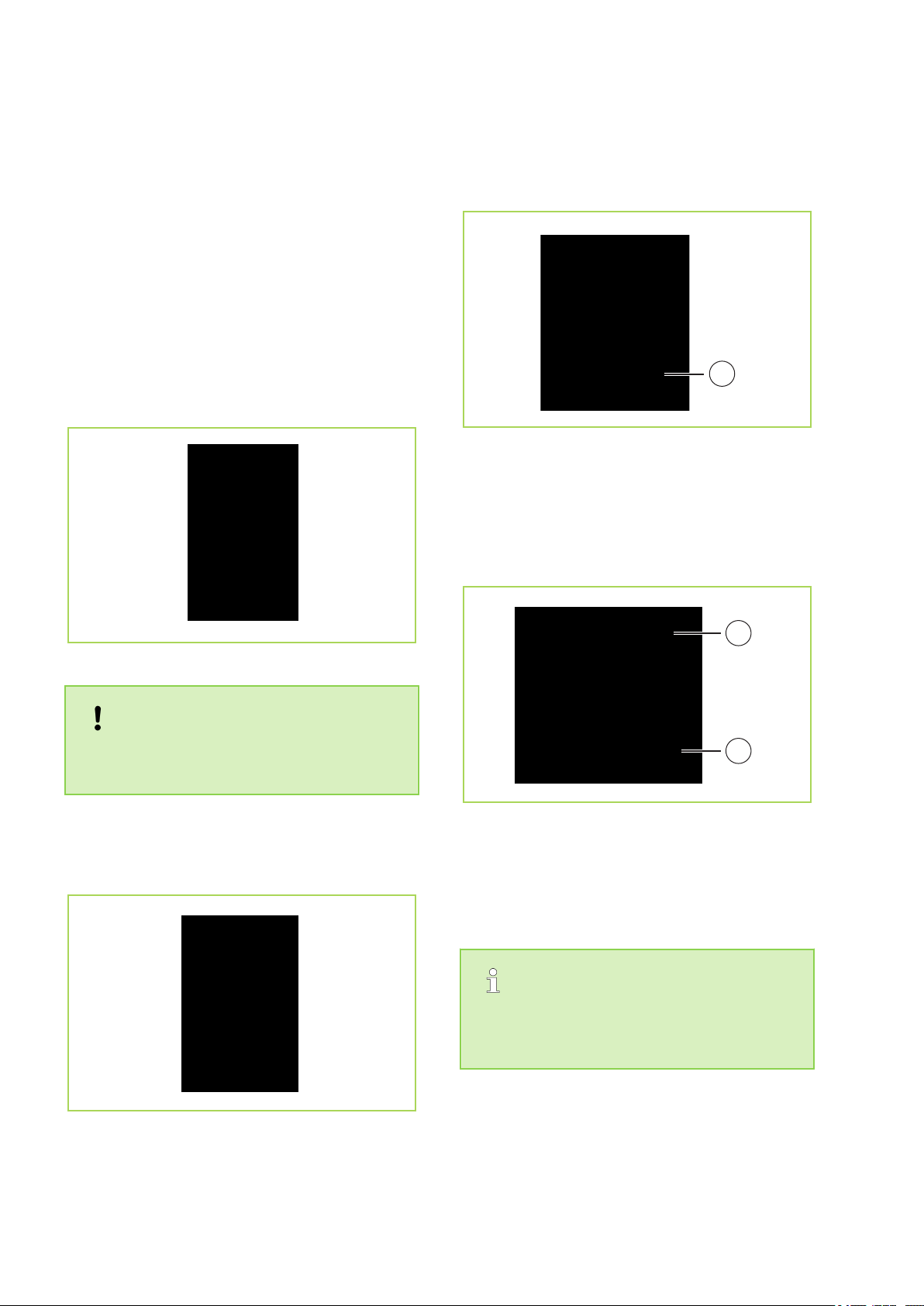
Design and function
Fig. 1: Front view
B: Air outlet, recirculation
1: Recessed grip
2: Infrared receiver
3: Ventilation louvres
4: Control panel
5: Conveyor rollers
Fig. 2: Rear view
A: Air inlet, recirculation
B: Air inlet, exhaust air
C: Air outlet, exhaust air
1: Air filter, recirculation
2: Air filter, exhaust air
3: Exhaust air hose
4: Condensate drainage with stopper
8

9
1
10
11
12
13
14
23
45
6
8
7
1
2
8
3
4
5
6
4
Operation
The system can be operated by means of the control panel on the unit or via the standard infrared remote
controller. The functional operation of the keys among themselves is identical, however, the designation can
vary. The batteries must be correctly inserted before the infrared remote control is used.
Fig. 3: Control panel
Legend
Key "I/O" (On/Off)
This key switches the unit on or off.
Operating mode "MODE" key
The actuation of this key allows the operator to
select between one automatic and three manual
fan stages in cooling mode (AUTO, HI, MED, LO)
or between recirculating mode (FAN). The LEDs
on the display
show the stage selected.
Adapted fan stages:
LED „AUTO“
Largest fan stage:
LED „HI“
Medium fan stage:
LED „MED“
Smallest fan stage: LED „LO“
With "AUTO" selected and with a large difference
between the target room temperature set and the
current room temperature, a high fan stage will be
automatically selected. Conversely, with a small
difference a small fan stage will be automatically
selected.
"AUTO SWING" key
The distribution of the air emerging from the unit
can be set with this key.
1. Key press = Continuous swing function
2. Key press = Swing function stopped
3. Key press = Continuous swing function
"▲/▼" keys "THERMO CONTROL"
By actuating the "▲/▼" keys the display changes
to the programmed target temperature. This can
be adjusted in a range of 18 to 30 °C in 1°C steps.
"SET TIMER" key
The automatic switching on or off of the unit can be
activated with this key. When switched off the
switch-on timer can be programmed in 1-hour
steps up to 24 hours with the "SET" button. The
same applies to the switch-off timer when the unit
is switched on. The LEDs 10 and 11 indicate the
activation.
Temperature/time adjustment
"RESET TIMER" key
The programmed timer can be cleared by
actuating the "RESET" 6 key.
9

7
8
9
10
11
12
13
14
REMKO RKL
"COMP. ON" key
Cooling capacity will now only be generated whilst
the compressor is active. Upon reaching the programmed target temperature, the compressor and
thus the cooling capacity will be switched off. The
recirculating fan however, continues to run. During
compressor operation the 7 LED illuminates.
Cooling mode: "AUTO, HI, MED, LO" LED
See 2.
NOTICE!
You will achieve a pleasant room temperature
if you set the desired target temperature max.
4 to 7 °C below the outside temperature.
Circulated air operation: "FAN" LED
In this operating mode the air in the room is recirculated in the unchangeable medium stage. The
unit does not cool the air.
"TIMING ON" LED
The switch on timer is active.
"TIMING OFF" LED
The switch off timer is active.
"DRAIN WATER" display
The condensate arising will be collected in an
internal reservoir, fed to the condenser and evaporated there. The evaporated condensate will then
be fed to the outside via the exhaust air hose. If
the condensate cannot be fed away then a fault
shut-down is initiated along with an LED 12 signalling this. In order to be able to use the unit again
after this fault shut-down, proceed as follows:
1. Switch the unit off with the "I/0" key and pull out
the power plug.
2. Place a suitable container underneath the condensate drain of the internal reservoir. The condensate drain is located on the lower centre on the
rear of the unit.
3. Pull out the stopper from the condensate drain
and collect the condensate that drains out.
4. Then insert the stopper once again.
Display
The programmed room temperature or the
remaining time for the timer is shown on the display.
"REMOTE" IR receiver
The IR remote control should be pointed at this
receiver sensor in order to guarantee the operation.
Infrared remote control
General Information
n With the unit switched on any change to the
settings will be automatically transferred to the
room air conditioner. The proper receipt of data
will be acknowledged with an audible "beep".
n To operate the remote control should be
pointed towards the receiver. The receipt of
data is only possible if there are no objects
between the transmitter and the receiver.
n If the system is shut down for an extended
period it is advisable to remove the batteries
from the remote control.
NOTICE!
Never use new and used batteries at the same
time, remove discharged batteries immediately
and replace these with new batteries of the
prescribed quality as there is a danger of discharged batteries leaking.
10

Inserting the batteries into the remote control
2
1
5
3
15
4
6
Before initial commissioning, insert the supplied
batteries (2 each, type AAA) into the remote control.
1. Slide the battery compartment cover on the rear
of the remote control to open it.
2. Insert the batteries with the correct polarity.
Observe marking in the battery compartment.
3. Close the battery compartment again.
Functions of the infra-red remote control
All settings of the unit can be implemented via the
remote control supplied. Please refer to the "Control panel" section for the functions of the keys.
The range of the remote control is ca. 5 metres.
Help save on energy consumption in stand-by
mode! If the device, system or component is
not in use, we recommend disconnecting the
power supply. Components with a safety function is excluded from our recommendation!
Fig. 4: Infrared remote control
1: On / off "POWER" key
2: Operating mode "MODE" key
3: "AUTO SWING" air distribution key
4: "TIMER SET" timer key
5: "TIMER RESET" timer key
6: "▲/▼" keys "THERMO CONTROL"
15: Infrared transmitter
11
1
1
1
2
REMKO RKL
5
Assembly and unit installation instructions
The unit is positioned at the desired location with
the discharge side pointing into the room. When
positioning, observe the following instructions:
n After unpacking the unit let it sit on its transport
n Set the unit down in a stable position on a level
Assembly and installation
rollers for at least 5 minutes before you switch
it on.
and firm floor. If the floor is uneven then this
can lead to vibrations and disturbing noises.
n Check whether the stopper in the condensate
drain is present and correctly installed. There is
a risk of uncontrolled condensate leakage after
commissioning.
Fig. 7: Condensate drain
1: Condensate drainage with stopper
n Never operate the unit without the air inlet filter.
Otherwise, the fins of the heat exchanger can
become dirty and the unit loses performance.
Fig. 5: Unit installation
NOTICE!
There must be a minimum clearance of 20 cm
between the rear of the unit and the wall.
n All extensions to the power supply must be of a
sufficient cable size and must only be used
fully rolled out.
Fig. 8: Air inlet filter
1: Recirculated air filter
2: Exhaust air filter
n Ensure that persons and sensitive objects,
such as plants, are not placed directly in the air
flow emerging from the unit.
In addition, with direct solar radiation close the
curtains and blinds and keep the windows and
doors closed during operation.
Fig. 6: Power supply
12

Conduct the warm exhaust air away
NOTICE!
The exhaust air hose should always be laid
rising in the direction of air flow and must not
be extended!
In cooling mode the unit creates warm moist
exhaust air, which must be conducted away from
the room to be cooled. For this reason it is necessary to plug the exhaust air hose into the outlet
opening on the rear of the unit.
n Ensure that the catches for the exhaust air
hose latch securely into the two openings of
the connection aperture. In order to be sure of
effective operation, do not lay the flexible
exhaust air hose with tight bends and do not
kink it and to prevent damage resulting to avoid
air carrying components!
Via a wall pass-through
The hose supplied is firmly attached to a wall passthrough. A suitable wall pass-through is available
as an accessory (Fig. 12).
Fig. 10: Exhaust air with open window
Fig. 9: Latch the hose into place
n The exhaust air of the unit contains a certain
amount of moisture. For this reason it is advisable to feed the exhaust air to the outdoor area
or to outdoors.
Exhaust air routing variants
You can route the exhaust air out of the building as
follows:
Via a flat nozzle
The flat nozzle supplied can be used in various different ways. It is possible to feed the flat nozzle
through an open window and fasten it by means of
Velcro and a window suction cup (Fig. 10). Likewise the flat nozzle can be hung in a tilted window
(Fig. 11).
Fig. 11: Exhaust air with tilted window
Fig. 12: Wall pass-though
NOTICE!
In some circumstances routing the exhaust air
via a firmly attached exhaust air hose, e.g.
through closed doors or windows, can lead to
negative pressure in the room in which the unit
is being used. If this should reduce the performance of the unit then arrange for the pressure to be equalised.
13

2
3
4
1
min. 460 mm
REMKO RKL
Installation scheme for wall pass-though (accessory)
Fig. 13: Installation example
1: External grill
2: Telescopic tube
Installation instructions
1. Create a core hole in the exterior wall (wall thickness 270-480 mm) with a diameter of at least 135 mm.
Watch out for any supply lines in this area!
2. Insert the slide tube into the wall pass-through created such that the outer tube (larger diameter) is on
the inside of the wall. In order to avoid cold bridges insulate the telescopic tube with suitable insulation
material.
3. Brick the slide tube into the core hole such that it sits flush on both sides of the wall.
4. Fasten the protection grid on the outside of the wall with 4 screws. Take rain ingress into account when
fitting the grid.
5. Insert the interior flap valve and fasten this likewise with 4 screws. The "Top" legend on the flap valve
6. When decommissioning the unit, e.g. before the start of the winter period, seal the opening in the flap
must be visible from the inside.
valve with the sealing cover in order to prevent air circulation.
3: Non-return flap
4: Sealing cover
14

6
Electrical drawings
Electrical wiring
Fig. 14: Electrical drawings
PCB1: Control panel
PCB2: Control board
SM: Swing motor
M1: Fan motor (evaporator)
M2: Fan motor (condenser)
KM: Condensate pump
CM: Compressor
OLP: Compressor fuse
CX1: Capacitor (M1)
CX2: Capacitor (M2)
CX3: Capacitor (CM)
TH: Temperature probe
We reserve the right to modify the dimensions and design as part of the ongoing technical development
process
MS1: Microswitch (tank full)
MS2: Microswitch (pump)
Colour coding:
BK: Black
BR: Brown
BU: Blue
GR: Grey
OR: Orange
R: Red
W: White
Y: Yellow
15

REMKO RKL
7
Before every commissioning the air inlet and outlet
openings should be checked for foreign bodies and
the air inlet filter must be checked for dirt. Blocked
or soiled grids and filters must be cleaned immediately, see "Care and maintenance" chapter.
Cooling mode
1. Switch the unit on with the "I/O" key.
2. Select cooling mode with the "MODE" key.
3. Set the desired target temperature with the
Recirculation mode
1. Switch the unit on with the "I/O" key.
2. Select ventilation mode with the "MODE"
Commissioning
The "AUTO" LED must illuminate.
"THERMO CONTROL" key. The selected
target temperature will be shown in the display. If the fan stage selected is too large or
too small then this can be adjusted with the
"MODE" key.
key. The "FAN" LED must illuminate.
16

8
The unit has been manufactured using state-of-the-art production methods and has been tested several
times to ensure that it works properly. If malfunctions should occur, please check the unit as detailed in the
list below. Please inform your dealer if the unit is still not working correctly after all the function checks have
been performed.
Fault description Cause Remedy
The unit does not start or switches
itself off.
The unit does not work or works at
reduced cooling capacity.
Troubleshooting and customer service
Master switch off. Switch on the main switch.
Power failure Check voltage and if necessary
Defective mains fuse Arrange to have exchanged
Power supply defective Repair by certified serv. centre.
Operational temperature range too
low or exceeded.
Internal reservoir full. Empty reservoir.
The ambient temp. of the unit lies
outside the operating range (18 to
35 °C).
Exhaust air hose kinked, extended,
routed downwards or blocked.
wait until turned on again.
Observe operational temperature range 18 to 35 °C.
Do not operate the unit outside
the operating range.
Ensure that there is a clear
path for the exhaust air.
The unit does not respond to the
infra-red remote control.
Filter contamination, inlet or outlet
blower openings blocked by foreign
bodies.
Minimum clearances too small. Observe minimum clearances.
Windows and doors open / heat
load was increased.
Negative pressure in the installation room whilst the unit is operating with wall pass-through.
"Cooling" operating mode is not
used.
Unit will be switched by means of
the timer function.
Temperature setting too high. Reduce temperature.
Overvoltage due to local lightning
strike.
Batteries in the remote control are
empty or the distance to the
receiver is too great.
After battery exchange, incorrect
polarity of batteries.
Clean filter.
Close doors and windows /
reduce heat load.
Balance out the pressure in the
installation room.
Use "AUTO, HI, MED or LO"
operating mode.
Press "I / 0" key again.
Switch unit off and separate
from the power supply for 5
mins., then start anew.
Insert new batteries / reduce
distance.
Insert the batteries with the correct polarity. Observe marking.
Condensate discharge on unit. Unit standing at an angle. Stand vertically.
The stopper for the condensate
drain is not correctly inserted or is
damaged.
17
Insert stopper correctly or
replace if necessary.

1
2
REMKO RKL
9
Regular care and observation of some basic points
will ensure trouble-free operation and a long
service life.
Care and maintenance
DANGER!
Prior to performing any work, ensure the equipment is disconnected from the voltage supply
and secured to prevent accidental switch-on!
Filter cleaning
The unit is equipped with two air filters. These can
be withdrawn from the rear of the unit. The filters
must be cleaned at regular intervals. Clean the air
filters at intervals of no more than 100 operating
hours. Reduce this interval in the case of heavily
contaminated air.
Please proceed as follows in order to clean the
unit:
1. Switch the unit off and pull out the power
plug.
2. Pull the filter out of the unit (Fig. 15)
3. Clean the dust off the filter. Use a vacuum
cleaner in the event of slight soiling. (
4. In the case of heavy soiling clean the filter
carefully in lukewarm water. (
5. Subsequently allow the filter to dry in the air.
6. Insert the filter back into the device.
7. Ensure that the filter is dry and undamaged.
Fig. 17)
Fig. 16)
Fig. 15: Filter removal
1: Recirculated air filter
2: Exhaust air filter
n Clean the unit using a damp cloth. Do not use
a jet of water.
n Do not use any caustic, abrasive or solvent-
based cleaning products.
n Only use suitable cleaning agents, even in the
event of severe soiling.
n Ensure that no moisture gets into the unit.
Clean the exhaust air and outlet openings regularly and thoroughly. This is where dirt most
often collects first
NOTICE!
Check the level of dirt on the on the exchanger
fins.
n Clean the air filter on the indoor unit at regular
intervals, and more frequently if necessary.
n It is recommended that you take out a mainte-
nance contract with an appropriate specialist
firm.
NOTICE!
Never operate the indoor unit without the original filter. The heat exchanger fins on the
indoor unit with soil up if operated without a
filter and the device will suffer performance
loss.
Fig. 16: Cleaning with a vacuum cleaner
This enables you to ensure the operational reliability of the plant at all times!
18

Fig. 17: Cleaning with lukewarm water
10
Never switch off the equipment by pulling out
the mains plug.
Temporary shutdown
If it is planned to shut down the unit for longer
periods e.g. during the winter, proceed as follows:
1. Let the unit run in recirculating operation for
2. Switch the unit off with the "I/O" key, pull out
3. Place a suitable container underneath the
4. Pull out the stopper from the condensate
5. Then insert the stopper once again. A
Shutdown
NOTICE!
ca. 2 hours in order to dry the surfaces of the
evaporator fins. This will transport the
remaining moisture out of the unit and this
will avoid unpleasant odours when the unit is
re-commissioned.
the power plug and wind up the power
supply. Ensure that the wiring is not kinked or
too severely bent. The line can be fastened
to the rear of the unit.
condensate drain of the internal reservoir.
The condensate drain is located on the lower
rear side of the unit.
drain and collect the condensate that drains
out.
missing stopper or an incorrectly inserted
stopper will result in condensate leaking out
after re-commissioning.
6. Store the unit in an upright position in a cool,
dry and dust-free location protected from
direct sunlight. Cover the unit with a synthetic
cover to protect it against dust if desired.
Permanent shutdown
The entire system should only be dismantled by a
specialist firm familiar with all environmental
aspects involved. REMKO GmbH & Co. KG or your
sales partner will be pleased to provide details of
refrigerant specialists in your area.
19

8
7
30
20
21
31
15
18
19
25
32
26
24
27
28
14
11
12
13
3
29
4
5
23
22
1
2
10
9
17
16
34
33
36
35
37
REMKO RKL
11
11.1
Exploded view and spare parts lists
Exploded view of the unit
Fig. 18: Exploded view drawing
We reserve the right to modify the dimensions and design as part of the ongoing technical development
process.
20

11.2
For ordering spare parts, please contact directly to the REMKO GmbH & Co. KG.
All their device the accompanying
To ensure the correct delivery of spare parts, please always the device type with the corresponding serial
number (see type plate)
No. Description RKL 300
1 Front panel
2 Recessed grip
3 Cover, control panel
4 Outlet grill
5 Fins
6 Shift lever for fins
7 Back wall
8 Air filter, recirculation
Spare parts list
IMPORTANT!
part numbers can be found in the download area on www.remko.de
RKL 300
RKL 360
RKL 360
9 Unit base
10 Conveyor rollers
Fan housing
11
(condenser fan)
Fan impeller
12
(condenser fan))
Fan motor
13
(condenser fan)
14 Condensate tray
15 Condenser
16 Condens. pump
complete
17 Float (reservoir)
Microswitch 1
18
(reservoir)
Microswitch 2
19
(reservoir)
20 Evaporator
By request with the serial number
21 Compressor, complete
22 Film for control panel
Control panel circuit
23
board
24 Control board
21

REMKO RKL
No. Description RKL 300
25 Fan motor (evaporator)
26 Evaporator housing
Fan housing
27
(evaporator)
Fan impeller
28
(evaporator)
29 Fin motor
30 Exhaust air filter
31 Power supply with plug
32 Compressor capacitor
Capacitor
33
(evaporator fan)
Capacitor
34
(condenser fan)
35 Exhaust air hose cpl.
36 Infrared remote control
37 Sensor air inlet
RKL 300
By request with the serial number
RKL 360
RKL 360
Spare parts not illustrated
Condensate catchment
tray
Accessories
Wall pass-though 1613118 1613118 1613118 1613118
By request with the serial number
22

12
A
Assembly........................................................... 12
C
Care and maintenance....................................... 18
Cleaning the filter............................................... 18
Condensate drain............................................... 12
Conduct the warm exhaust air away.................. 13
D
Disposal of equipment......................................... 6
E
Environmental protection..................................... 6
Exhaust air filter................................................. 12
Exhaust air routing variants
Exploded view drawing ..................................... 20
Exploded view of the unit................................... 20
I
Installation.......................................................... 12
M
Maintenance...................................................... 18
O
Operation
Index
Via a flat nozzle.............................................
Via a wall pass-through........................... 13, 14
Control panel................................................... 9
13
R
Recirculated air filter.......................................... 12
S
Safety
Dangers of failure to observe the safety
notes............................................................... 4
General........................................................... 4
Identification of notes...................................... 4
Notes for inspection........................................ 5
Notes for installation....................................... 5
Notes for maintenance.................................... 5
Personnel qualifications.................................. 4
Safety-conscious working............................... 4
Safety notes for the operator.......................... 5
Unauthorised modification ............................. 5
Unauthorised replacement part manufacture.. 5
Set-up................................................................ 12
W
Warranty.............................................................. 5
23

REMKO RKL
24

25

REMKO RKL
26


Consulting
Thanks to intensive training,
our consultants are always
completely up-to-date in terms
of technical knowledge. This has
given us the reputation of being
more than just an excellent,
reliable supplier:
REMKO, a partner
helping you find solutions to
your problems.
Distribution
REMKO offers not just a well
established sales network both
nationally and internationally, but
also has exceptionally highlyqualified sales specialists.
REMKO field staff are more than
just sales representatives: above
all, they must act as advisers to
our customers in air conditioning
and heating technology.
SFlbCustomer Service
Our equipment operates
precisely and reliably. However,
in the event of a fault, REMKO
customer service is quickly at
the scene. Our comprehensive
network of experienced dealers
always guarantees quick and
reliable service.
REMKO INTERNATIONAL
… and also right in your neighbourhood!
Make use of our experience and advice
We reserve the right to make technical changes, and provide no guarantee as to the accuracy of this data!
REMKO GmbH & Co. KG
Air conditioning and heating technology
Im Seelenkamp 12 D-32791 Lage
Postfach 1827 D-32777 Lage
Telephone +49 52 32 606-0
Telefax +49 5232 6 06-260
E-mail info@remko.de
Website www.remko.de
 Loading...