

REMKO PGM Series, PGM 30 E, PGM E Series, PGM 30, PGM 60 E Operating And Installation Instructions
...
Operating and
installation instruction
REMKO PGM (E) series
Propane gas heating systems
PGM 30 (E), PGM 60 (E)
This product is not suitable as a main heater.
Edition GB - Q04 Read the instructions prior to performing any task!


Contents
Safety notes 4
Unit description 5
Installation instructions 6
Gas connection 7-9
Commissioning 9-10
Shutdown 11
Care and maintenance 11-12
Troubleshooting 13
Intended use 14
Customer service and guarantee
Environmental protection and recycling 14
Exploded view of PGM 30
Spare parts list for PGM 30 17
Exploded view of PGM 60 18
Replacement parts list for PGM 60 19
Maintenance protocol 20
Technical data
Electrical wiring diagram 22
21
14
16
Carefully read this operating manual prior to commissioning/using
the unit!
This operating manual is a translation of the German original.
These instructions are an integral part of the unit and must always be
kept in the vicinity of the installation location or on the unit itself.
Subject to modifications; no liability accepted for errors or misprints!
3

REMKO PGM (E) series
Safety notes
Always observe the respective local building code and fire prevention guidelines as well as the guidelines of
the accident prevention and insurance associations when using the units.
The units have been subjected
to extensive material, functional
and quality inspections prior to
delivery. However, dangers can
arise from the units if they are
used improperly or not as intended
by untrained personnel!
Please observe the following
information:
■
The units may only be operated
by persons that have been
instructed in their operation
■
The power plug must be pulled
out of the mains socket before
maintenance and repair work
■
The units must be installed such
that they are stable on a noncombustible surface
■
It is necessary to ensure
that no flammable objects
or materials can be drawn in
■
This unit can be used by
children above the age of
8, as well as by people with
impaired physical, sensory or
mental capabilities or a lack
ofexperience and knowledge
if they are supervised or have
received instruction in the safe
operation of the unit, and if
they understand the associated
potential hazards. Children must
never play with the unit.
■
Cleaning and user maintenance
must not be carried out by
unsupervised children.
■
The units must be installed and
operated in such a way that
personnel are not endangered
by exhaust gases and radiant
heat and no fires may occur
■
Portable liquid gas tanks must
be installed such that they are
stable and upright
■
Liquid gas tanks must never
be used whilst lying horizontal
during unit operation
■
All unit electrical cables must be
protected against damage, e.g.
by animals
■
The units must then only
be operated in areas where
the units can be supplied with
an adequate amount of air
for combustion
■
The units must only be installed
in well-ventilated spaces and
away from flammable materials.
Personnel must not remain
in the installation area
Appropriate prohibition
signs should be put up
at the entrances!
■
A safety zone of 1.5 m must
be maintained around the units,
incl. to non-combustible items
■
A minimum distance of 3 m
must be maintained from the
unit outlet
■
The unit outlet must not be
restricted or fitted with hoses
or pipes
■
Never insert foreign objects
in the unit
■
The air intake grille must always
be kept free of dirt and loose
objects
■
The units must not be exposed
to direct jets of water
e.g. pressure washers, etc.
CAUTION
The units must not be used
for heating living spaces
in residential buildings.
!
CAUTION
If there is a gas leak,
immediately close the shut-off
valve to the gas supply system,
switch off the gas heater,
unplug the power plug, open
windows/doors for ventilation
and seek the cause of the gas
leak in order to neutralise this.
Do not use the unit again
before the gas leak has been
eliminated!
4

Unit description
The units are mobile fan-assisted
air heaters (WLE) directly fired
with liquid gas, without a heat
exchanger.
The units operate without an
exhaust gas connection and
are designed exclusively for
commercial use.
The units are equipped with
integrated power regulation
for the stepless control of
the heating capacity, quiet and
low-maintenance axial fans,
robust gas burners with thermal
monitoring, electric solenoid valve,
piezo ignition and mains cable with
earthed safety plug.
The units are intended exclusively
for manual operation and cannot
be thermostatically controlled.
The units conform to
the fundamental health and safety
requirements of the appropriate
EU stipulations and are simple
to operate.
The units are EC type-tested,
DVGW-registered and approved
for EU countries.
The units may be used among
other things for the following:
■
Drying newly completed
buildings
■
Spot heating of outdoor
workplaces
■
Spot heating workplaces
in open, non-flammable
manufacturing facilities and
halls
■
Temporarily heating enclosed
spaces with a sufficient fresh air
supply
■
De-icing machines, vehicles and
non-combustible warehoused
goods
■
Maintaining the temperature
of frost-sensitive parts
Operating sequence
After switching on the units,
the supply air fan is put into
operation and the electric solenoid
valve is opened.
However, the gas supply to
the burner remains closed at this
point.
Only after actuating the pressure
pin of the safety pilot is the gas
supply to the gas burner enabled.
The liquid gas is now transported
through the gas nozzle under
pressure into the mixing tube.
Here, the liquid gas is enriched
with a quantity of oxygen
determined based on the
respective burner output.
The gas/air mixture produced in
this way is ignited at the burner
head by an electric ignition spark.
The ignition spark is generated
through the manual actuation of
the piezo igniter.
The heating of the thermocouple
activates the thermal monitoring
of the flame in operation.
The pressure pin of the safety pilot
must now be released.
In the event of any irregularities
or if the flame is extinguished,
the gas supply is interrupted.
A safety temperature limiter (STB)
interrupts with an overheating
of the gas supply and interlocks
all unit functions.
Regulation of the min/max heating
capacity can be implemented on a
stepless basis during unit operation
on the integrated “power
regulation”.
NOTE
For optimum operation
the units should not be
operated above an ambient
temperature of 25 °C.
Monitoring the units
It is possible to safely monitor all
functions with the safety devices
of the units.
In the event of irregularities or if
the flame is extinguished, the units
are switched off and interlocked.
Safety temperature limiter (STB)
The units are equipped with a
safety temperature limiter (STB),
which interrupts the gas supply
in case of overheating and
electrically interlocks the unit.
A manual reset of the STB can only
be implemented after the units
have cooled down.
CAUTION
If the safety temperature
limiter has been triggered,
the cause of the malfunction
must be identified and rectified
before a reset is performed.
The STB is reset by actuating
the reset key 2.
1. Unscrew the protective cap 1.
2
1
2. Push in the pressure pin 2.
3. Screw the protective cap 1 back
on again.
CAUTION
Safety devices must not
be bypassed or disabled.
5

REMKO PGM (E) series
Installation instructions
■
The safety regulations
of the accident prevention
and insurance associations,
the respective regional building
regulations and the combustion
appliances regulations apply
to operation of the units.
For example, for Germany:
Combustion plant order (FeuVo)
■
for the individual federal states
Accident prevention regulations
■
DGUV Regulation 79 “Use of
liquid gas”
Workplace directives ASR 5
■
Workplace regulations §§ 5
■
and 14
Outdoor installation
■
The operation of the units
must not present a hazard
or unreasonable loading
■
The unit operator must
ensure that it is not possible
for unauthorised persons
to manipulate either the unit
or the power supply
■
To prevent damage due
to inclement weather, units
installed outdoors must be
adequately protected
Installation in enclosed, wellventilated rooms
■
The units are designed without
an exhaust gas connection
according to type, and can
only be used in enclosed rooms
on a conditional basis
■
Reliable extraction of
the combustion gases must be
guaranteed in all cases in order
to exclude impermissible
contamination of the room
air with hazardous substances
The fresh air supply required
for trouble-free combustion
must be ensured. It is practical
to have the fresh air supply
provided by windows and
doors or through appropriately
dimensioned openings
in the outside wall
■
The units must not operate
continuously whilst unattended
The units may only be operated
in rooms if:
■
a sufficient quantity of air
is supplied to the units for
the combustion
■
these are well ventilated and
aerated
the proportion of substances
■
harmful to health in
the breathing air is at a harmless
level
There is good natural ventilation
and aeration if:
1.
the room volume in m3 is at
least 30 times the nominal
heating capacity kW of all of
the units operating in the space,
and if the natural change of air
is guaranteed by windows and
doors or
constantly open ventilation
2.
openings are present for
incoming and exhaust air in
the vicinity of the ceiling and
floor, whose size in m2 is at least
0.003 times the nominal heating
capacity in kW of all of the units
operating in the space.
!
CAUTION
For use in public buildings,
national regulations must
be observed.
CAUTION
The units must only be
installed in well ventilated
spaces and not in living areas
or similar recreational areas.
6

Gas connection
The gas connection / unit
operation must take place
exclusively on the basis of
the accident prevention regulation
DGUV 79 “
as well as the respective local
construction and fire prevention
regulations.
The fuel supply must be installed
in accordance with DIN 4755 for
oil-fired warm air heaters, DVGW
Code of Practice G 600 for gasfired warm air heaters and TRF for
liquid gas.
The units are operated with liquid
gas in accordance with DIN 51622.
They require a constant
connection pressure of 1.5 bar.
It is prohibited to exceed or
undershoot the connection
pressure.
CAUTION
A constant unit connection
pressure of 1.5 bar (1500
mbar) must be guaranteed,
also in continuous operation.
■
When using longer hose lines,
consider the respective pressure
loss
■
Only use components that have
been tested and are suitable for
the respective purpose, such
as gas hose, pressure controller
and hose breakage protection
or leak gas protection
Use of liquid gas”
unit
,
CAUTION
Before all work on the gas
supply and when replacing
gas cylinders, all shut-off
valves must be closed and no
ignition sources are permitted
in the immediate vicinity.
■
The use of longer hose lines
is permissible if:
- special operational reasons exist
- appropriate additional safety
measures are observed and
the hose lengths are kept
as short as possible
■
Hose lines must be
fundamentally protected
against chemical, thermal and
mechanical damage
■
In particular, torsional stress
must be avoided
■
The units may only be operated
out of the gas phase
■
The units must be serviced
by qualified persons only
■
Only original spare parts may
be used for repairs
■
Unit parts that are prone to
wear and ageing (e.g. gas
hoses) must be replaced at
regular intervals
■
Gas connection nipple on
the unit - G1/4 LH - KN
■
All common gas cylinder sizes
are permitted for the gas
supply. However, a gas
cylinder with at least 11 kg
filling weight is recommended.
For longer operation and
nominal heat outputs above
50 kW, it is recommended that
the gas be drawn from several
gas cylinders in parallel. (Multicylinder accessories set)
NOTE
This does not apply
if the correct condition
is confirmed by an expert.
CAUTION
The units must not be used
below ground level
in basements, without suitable
gas monitoring equipment.
NOTE
It is prohibited to exceed
or undershoot the required
connection pressure.
, e.g.
■
If possible, the length of the gas
hose should not exceed 2 m
■
Only pressure controllers with
a fixed outlet pressure setting
are permitted. The units may
only be operated out of the gas
phase
■
When selecting the hose, make
sure that the pressure class is
sufficient
7

REMKO PGM (E) series
Connecting the gas supply
1. Connect pressure
controller
to the gas
cylinder or gas
supply system.
Observe left-handed thread!
2. Open cylinder
valve(s) or shutoff valve of the
supply line.
With simultaneous discharge
from multiple gas cylinders, all
valves must be opened.
3. Push the unlock
button on
the hose breakage
protection after
opening
the valve(s).
This process is also necessary
after every cylinder change.
4. Check all gas connections for
leak-tightness using suitable
media.
for example with:
Soap solution or
leak detection
spray.
Assembly note
During the assembly or
disassembly of the gas hose, it is
necessary to counter-hold
by the gas connection nipple
with an open-end wrench size 17,
whilst observing the left-handed
thread.
This process also applies
to the pressure controller, hose
breakage protection and all further
gas components.
Tighten gas hose:
Turn the union nut anticlockwise
counter-hold
Loosen gas hose:
Turn the union nut clockwise
counter-hold
the unit
Icing up of gas cylinders
With insufficiently dimensioned
gas supply systems, there is a risk
of the pressurised gas cylinder
icing up.
Due to the reduction of the gas
pressure, it is no longer possible
to guarantee the correct gas
supply to the unit.
Crystalline frost formation on
the gas cylinder(s) must not
be defrosted with naked flames,
glowing objects, radiators, etc.
In order to avoid the gas
cylinder(s) icing up, it is necessary
to configure the gas supply
in accordance with the unit
connection value, the time
in operation and the ambient
temperature of the supply tank.
Attachment multi-cylinder set (accessory)
NOTE
Because these are ball
nipple screw connections
in accordance with DIN 4815,
part 2, only appropriate,
fitting hoses may be used.
NOTE
Only hoses for liquid gas in
accordance with DIN EN 16436-1,
pressure class 30 may be used
for construction site operations.
8
In order to ensure a regular gas take-off insofar as possible,
all cylinder valves must be open.
The cylinder battery can be expanded with ease,
through the use of additional sets.
Legend:
1 = Gas hose to the unit
2 = Hose breakage protection
3 = Gas pressure controller
4 = HP hose 0.4 m
5 = T-connection
6 = Cylinder valve
6
5
6
4
6
4
1
2
3
5
s
s
s

s
s
s
Commissioning
Tank gas systems
When connecting the units to tank
gas systems, ensure sufficient pipe
dimensions depending on the pipe
length.
A sufficient gas supply to the
consumer system can be ensured
through the use of an evaporator.
In order to guarantee the faultless
unit function, it is advisable to
install a permanently set pressure
controller with 1.5 bar outlet
pressure and corresponding gas
throughput (see unit name plate),
as well as a shut-off device tailored
and approved for the respective
pre-pressure.
In order to avoid malfunctions
of the unit’s control and safety
equipment due to harmful
substances such as rust and dust
from the gas supply line or tank(s),
it has proven to be essential to
install gas filters before the control
and safety equipment of the units
(see DIN EN 676 and TRF 88
section 5).
The units should be checked for
visible defects on the operating
Connecting the units
to the electrical power supply
and safety devices as well as
proper installation and correct
electrical and gas connections
before commissioning.
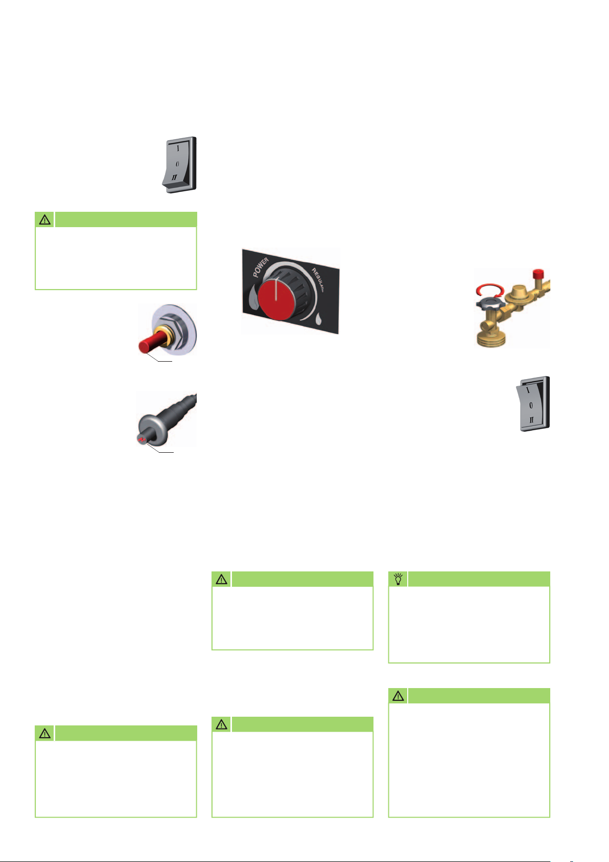
1. Move the operating
switch to the "0"
(off) position.
A person, who has been
adequately trained in the handling
of the units and the use of liquid
gas per DGUV 79, must be tasked
with operation and monitoring
of the units.
2. Connect the unit's power
plug to a properly
installed and fused
mains socket.
Connect 230 V/50
Hz.
CAUTION
In the event of defects that
endanger the operational
safety of the units, operation
of the units must be
discontinued immediately and
NOTE
The electrical connection for
the units must be made at a
separate feed point with a residual
current device in accordance with
VDE 0100, Section 55.
the supervisor informed!
Before the unit start, ensure that the gas supply cylinders are correctly
secured and are not positioned directly in the heat radiated by the units.
The pressurised gas tanks must be positioned to the side / rear
of the unit.
NOTE
Installation work on the tank
gas systems and the supply
lines may only be performed
by qualified specialist
personnel.
CAUTION
Before all work on the gas
supply and when replacing
gas cylinders, all shut-off
valves must be closed and no
ignition sources are permitted
in the immediate vicinity.
CAUTION
The tanks must never
be heated or de-iced through
the unit hot air flow.
There is a risk of explosion!
CAUTION
Pressurised gas tanks must
not lie horizontal when used
during unit operation.
Gas outlet in the liquid phase.
9
REMKO PGM (E) series
Heating mode
1. Move the operating
switch to the "I" position.
The supply air fan starts
up.
CAUTION
Before executing the
ignition process, check to
ensure the correct function
of the supply air fan.
2. Push in the pressure
pin 2 of
the safety pilot
and hold down.
2
3. With pressure
pin 2 depressed,
after approx. 2 to 3
sec.actuate
the piezo igniter 3.
If necessary, actuate
the piezo igniter multiple times.
4. After a flame appears, depress
the pressure pin 2 for a further
approx. 10-15 sec. until
the thermal flame monitoring
is activated.
5. If the flame goes out when
the pressure pin 2 is released,
repeat the ignition process.
Observe a waiting time of
approx. 1 minute.
3
Setting and controlling
the heating capacity
The desired or required heating
capacity can be steplessly set
on the “power regulation”.
Turning to the left:
higher heating capacity
Turning to the right:
lower heating capacity
The heating capacity can also be
steplessly changed during unit
operation.
Safety distances
■
For safe operation, a 1 m safety
distance must be maintained
around the unit
■
A minimum distance of 3 m
must be maintained from
the unit outlet
CAUTION
It is essential to observe
the necessary safe distances
from flammable and fire
hazardous materials.
Ventilate
In this operating mode, the supply
air fan runs permanently.
The units can be used for air
recirculation or ventilation
purposes.
1. Close the shut off valve(s)
of the gas supply system and
allow the gas flame to burn out.
2. Move the operating
switch to the "II"
(Ventilate) position.
No heating operation is possible
in this operating mode.
NOTE
Overpressure and underpressure
in the installation area
should be avoided as this will
inevitably lead to combustionrelated faults.
With a repeat ignition process,
hold the pressure pin for a little
longer if necessary.
CAUTION
The units must not be used
below ground level
in basements, without suitable
gas monitoring equipment.
10
, e.g.
■
Flooring and ceilings must be
fire retardant
CAUTION
In case of a gas leak, halt unit
operation immediately.
All gas shut-off valves must
be closed and the units
disconnected from the power
supply.
CAUTION
It must be ensured that supply
air can be freely sucked in and
that heated air can be blown
out without obstruction.
The unit intake and outlet
must not be restricted or fitted
with hoses or pipes.

Shutdown
Care and maintenance
1. Close the shut off valve(s)
of the gas supply system and
allow the gas flame to burn out.
2. Move the operating
switch to the "0"
(off) position.
3. If the units are
inactive for longer
periods, disconnect
them from the mains
power supply.
NOTE
Regular care and maintenance,
at the latest after every
heating period, is the basic
requirement for a long service
life and malfunction-free
operation of the units.
In accordance with the operating
conditions, the units must be
checked as and when required,
but at least every two years, by
a specialist to ensure that they
are in a condition that is safe
to use.
The results of this test must be
recorded in a test certificate.
The test certificate must be stored
until the next test and presented
for inspection by authorised
persons on request.
■
Check the inlet and outlet grille
for contamination on a regular
basis
■
Check hoses and seals for
damage on a regular basis
■
Replace damaged hoses, seals,
etc. immediately
■
Clean the gas burner, gas
nozzle and the combustion air
openings regularly
■
Check ignition and ionisation
electrodes regularly and adjust
and clean if necessary
CAUTION
Before undertaking any work
on the unit, the gas supply
must be shut off and the power
plug must be removed from
the mains socket.
■
Keep the units free of dust and
other deposits
■
Only clean the units with a dry
or moistened cloth
■
Never use direct jets of water.
such as high-pressure cleaners
etc.
■
Never use abrasive or solvent-
based cleaners
■
Use only suitable cleaners, even
for heavy contamination
NOTE
Replace defective or damaged
parts immediately and
exclusively with original spare
parts.
NOTE
Adjustment and maintenance
work may only be carried out
by authorised and qualified
technicians.
CAUTION
An electrical safety check must
be carried out in accordance
with VDE 0701 after any work
on the units.
11
REMKO PGM (E) series
Disassembling and cleaning
the gas burner
1. Switch off the gas supply
to the unit and remove the
power plug from the mains
socket.
2. Remove the protective outlet
grille, exterior cladding and
inspection cover.
3. Undo the clamping screw 6
of the nozzle holder.
4. Remove the ignition cable from
the ignition electrode 4.
5. Detach the capillary tube 3
of the thermocouple from the
safety pilot.
6. Loosen the clamping screw 5
on the electrode bracket and
carefully draw out the ignition
electrode.
7. Carefully pull the thermocouple
with capillary tube down and
out.
Be aware of the extremely
sensitive capillary tube here!
10. Carefully clean the gas burner
with a suitable brush and
possibly compressed air.
11. Clean the gas nozzle
if necessary.
Do not use any sharp-edged
objects!
12. Carefully remove deposits
or soiling in the unit base.
13. After all cleaning work on
the gas burner, carefully refit
all parts in reverse order.
14. After using the gas nozzle,
tighten the clamping screw 6
again.
15. Adjust the ignition
electrode and thermocouple
in accordance with the sketch
and tighten the clamping
screw 5 of the electrode
bracket.
16. Carefully refit all parts
of the unit in reverse order.
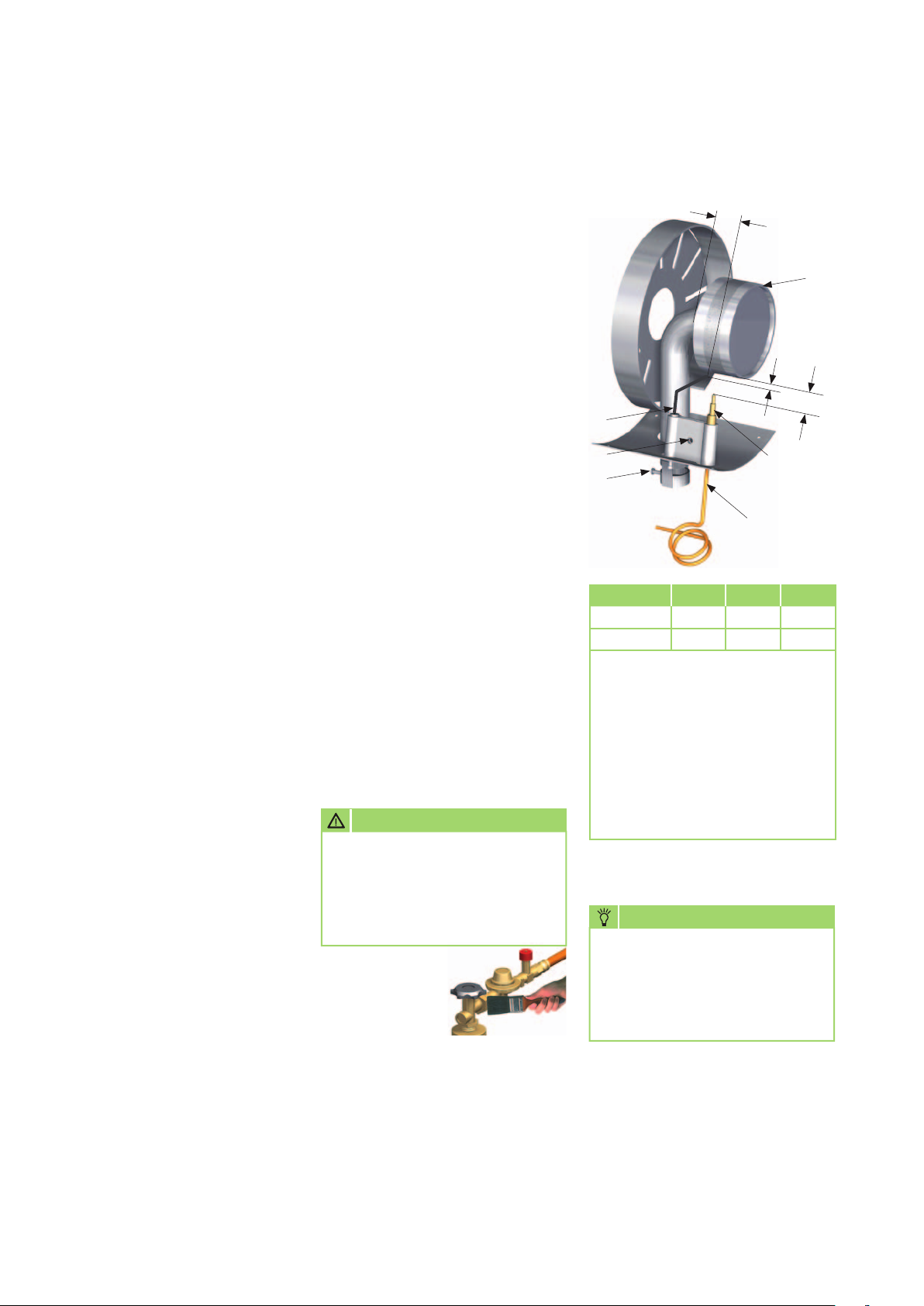
CAUTION
Gas burner
B
A
4
5
6
Unit type A B C
PGM 30
PGM 60
All dimensions in mm
Legend:
1 = Gas burner
2 = Thermocouple
3 = Capillary tube
(fixed component of the thermocouple)
4 = Ignition electrode
5 = Clamping screw (electrodes)
6 = Clamping screw (gas nozzle)
approx. 3 approx. 15 approx. 20
approx. 3 approx. 15 approx. 35
2
3
1
C
8. Carefully remove any adhered
deposits from the ignition
electrode and thermocouple.
9. Detach the fastening screws
of the gas burner and remove
the complete gas burner from
the unit.
12
A functional inspection of
the entire unit including leak
testing of all gas-conveying
connections must be
conducted
for example with:
Soap solution or
leak detection
spray.
NOTE
A strongly yellowy flame
indicates an inadequate
fresh air supply or dirt inside
the unit.

Troubleshooting
Malfunctions: Cause:
The unit does not start.
The unit switches off during operation.
The fan runs, but the gas supply is blocked
or no flame appears.
The flame extinguishes after the pressure pin of the safety pilot
is released.
The gas supply is interrupted,
or the flame is extinguished.
The unit consumes too much fuel.
The unit cannot be switched off.
The heating capacity drops in permanent operating mode.
1 – 2 – 3 – 4 – 7
2 – 4 – 7 – 12 – 13
4 – 5 – 8 – 9 – 12
8 – 10 – 11
4 – 6 – 7 –10 – 11 – 12 – 13
12 – 15
3 – 14
13
Cause: Remedial measures:
1. The unit is not connected to the electricity supply.
2. The fan motor is overloaded or the supply air fan runs irregularly
or is blocked.
3. The operating switch is defective.
4. No gas pressure.
Connect the plug with an appropriate socket (230V/50Hz).
Replace the plug if it is defective.
Check the motor, fan blade and drive clutch.
Replace the operating switch.
Check whether the gas supply to the unit is present.
Check the contents of the gas cylinders.
Check the gas hose for damage.
Disengage or replace the hose breakage protection.
5. No ignition sparks are generated.
6. The protective intake grille of the supply air fan is contaminated.
7. The temperature limiter triggers a switch-off.
8. The safety pilot does not open the gas supply
or keep it open.
9. The piezo igniter is defective.
10. The thermocouple or temperature limiter are defective.
11. Loose or dirty connection between the safety pilot and
thermocouple.
12. The pressure controller is defective or an incorrect pressure controller
is fitted, or the hose breakage protection (Sbs) has locked.
13. The gas cylinder(s) is (are) iced up due to an excessively high gas
take-off and low temperatures.
14. The solenoid valve does not close - Close the gas supply.
15. Leaky gas line.
Set the ignition electrode in accordance with specifications.
Check the ignition cable.
Check the porcelain insulation of the electrode.
Clean the protective intake grille.
Check the protective intake and outlet grilles (clean if necessary).
Check whether the fresh air supply is sufficient.
Replace the safety pilot.
Replace the piezo igniter.
Check the thermocouple or temperature limiter and replace
if necessary
Check the connection and clean if necessary.
Fit an original pressure controller.
Disengage or replace the hose breakage protection.
Replace the gas cylinder(s) and connect 2-3 cylinders with the multicylinder set, EDP no. 1014050.
Allow the flame to burn out.
Set the operating switch to the "0" position and remove the power
plug from the mains socket.
Replace the solenoid valve.
Use foaming media to search for the leak and remedy this.
13

REMKO PGM (E) series
Intended use Customer service and
guarantee
The units are designed
exclusively for heating and
ventilation purposes in industrial
or commercial use (not for living
space heating in private use)
on the basis of their structural
design and equipment.
According to DIN EN 1596,
the device definition is “warm air
heaters not intended for domestic
use without heat exchangers with
forced convection”.
The units must only be operated
by appropriately instructed
personnel.
With non-observance
of the manufacturer's
specifications, the respective
local legal requirements or after
arbitrary alterations to the units,
the manufacturer shall not be
liable for resulting damages.
As a prerequisite for any
guarantee claims to be
considered, it is essential
that the ordering party or their
representative complete and return
the "certificate of guarantee"
to REMKO GmbH & Co. KG at the
time when the units are purchased
and commissioned.
The units were tested
at the factory
several times to verify their correct
function.
However, if malfunctions should
arise that cannot be remedied by
the operator with the assistance
of the troubleshooting section,
please contact your specialist
dealer or contractual partner.
Environmental protection and recycling
Disposing of packaging
When disposing of packaging
material, please consider
our environment.
Our units are carefully packed
and delivered in sturdy transport
packaging made from cardboard
and polystyrene.
The packaging materials are
environmentally-friendly and can
be recycled.
By recycling packaging materials,
you make a valuable contribution
to the reduction of waste and
conservation of raw materials.
Therefore, only dispose of
packaging material at appropriate
collection points.
Disposal of the old unit
NOTE
Operation other than the types
listed in this operating manual
is prohibited.
With non-observance, any
manufacturer liability or guarantee claims are voided.
!
CAUTION
Copyright
The redistribution, even
in part, or the use of this
documentation for purposes
other than intended is
prohibited without the written
authorisation of
REMKO GmbH
& Co. KG
.
NOTE
Adjustment and maintenance
work may only be carried out
by authorised and qualified
technicians.
The manufacturing process for
the units is subject to continuous
quality control.
Only high-grade materials are
processed, the majority of which
are recyclable.
You also contribute
to environmental protection
by ensuring that your old
equipment is only disposed
of in an environment friendly
manner.
Therefore, only bring the old
unit to an authorised recycling
business or to an appropriate
collection point.
14

15

REMKO PGM (E) series
Exploded view of PGM 30 (E)
31
29
32
33 34
28
1
2
27
26
25
24
30
23
15
19
17
21
12
20
14
19
18
15
9
14
12
16
13
10
35
37
36
11
10
9
7
8
6
3
4
5
6
16
We reserve the right to modify the dimensions and design as part of the ongoing technical development process.

Spare parts list
No. Description EDP no.
1 Transport handle 1101142
2 Exterior cladding PGM 30 1101405
2a Exterior cladding PGM 30 E 1101477
3 Combustion chamber 1121186
4 Completion panel, front 1101479
5 Protective outlet grille 1101383
6 Safety temperature limiter 1101197
7 Inspection cover 1101385
8 Terminal block 6x 1101366
9 Thermocouple 1101164
10 Ignition cable 1101283
11 Ignition electrode 1101180
12 OT elbow union 1101316
13 Gas nozzle 1101159
14 Gas supply pipe Z/D 1101452
15 Gas supply pipe M/R 1101441
16 Piezo igniter 1101364
17 Gas control 1101411
18 Screw connection M10x1 1101409
19 Gas supply pipe R/Z 1101451
20 IT elbow union 1101468
21 Safety pilot 1101169
23 GE-screw connection 1101396
24 Solenoid valve 1101376
25 Gas connection nipple 1101134
26 Adjusting knob, cpl. 1101192
27 Operating switch 1101188
28 Strain relief 1101267
29 Mains cable with plug 1101320
30 Completion panel, rear 1101480
31 Fan motor 1108049
32 Drive clutch B 6 Ø 1108455
33 Fan blade 1101392
34 Clutch plate 1101375
35 Gas burner 1101417
36 Grommet 1101304
37 Retaining clip 1101395
xx Pressure controller with hose breakage protection 1101470
xx 2 linear m. Gas hose 1101419
xx 2 linear m. HP gas hose (version for construction site operation per DIN 4815 part 1, pressure class 30) 1101174
xx 5 linear m. HP gas hose (version for construction site operation per DIN 4815 part 1, pressure class 30) 1108410
xx 10 linear m. HP gas hose (version for construction site operation per DIN 4815 part 1, pressure class 30) 1108411
xx Multi-cylinder set (2-3 cylinders) 1014050
xx T-connection for multi-cylinder set 1101177
xx Nylon seal for T-connection 1101178
xx HP hose 0.4 m for multi-cylinder set 1101179
xx = not illustrated
When ordering replacement parts, please always state the EDP no. and unit number (see name plate)!
17

REMKO PGM (E) series
Exploded view of PGM 60 (E)
36
37
38
39
41
34
1
2
3
28
16 22
11
35
21
20
27
33
17
24
23
32
15
14
13
31
29
26
19
8
18
12
30
22
16
4
7
8
24
9
10 12
11
40
5
6
18
We reserve the right to modify the dimensions and design as part of the ongoing technical development process.

Spare parts list
No. Description EDP no.
1 Transport handle 1101142
2 Exterior cladding PGM 60 1101420
2a Exterior cladding PGM 60 E 1101461
3 Insulation 1101421
4 Combustion chamber 1101422
5 Gas burner 1101423
6 Protective outlet grille 1101424
7 Gas nozzle 1101426
8 Gas supply pipe Z/D 1101458
9 OT elbow union 1101316
10 Ignition electrode 1101280
11 Ignition cable 1101283
12 Thermocouple 1101164
13 Support, front 1101427
14 Unit base 1101428
15 Inspection cover 1101469
16 Gas supply pipe R/Z 1101459
17 IT elbow union 1101468
18 Safety pilot 1101169
19 GE-screw connection 1101359
20 Gas control 1101412
21 Screw connection M10x1 1101409
22 Gas supply pipe M/R 1101441
23 Support, rear 1101249
24 Safety temperature limiter 1101197
26 GE-screw connection 1101396
27 Solenoid valve 1101376
28 Piezo igniter 1101364
29 Gas connection nipple 1101134
30 Adjusting knob, cpl. 1101192
31 Strain relief 1101267
32 Operating switch 1101188
33 Terminal block, 6x 1101366
34 Grommet 1101304
35 Mains cable with plug 1101320
36 Protective intake grille 1101432
37 Fan motor 1101254
38 Drive clutch B 8 ø 1101255
39 Fan blade 1101150
40 Retaining clip 1101395
41 Clutch plate 1101375
xx Pressure controller with hose breakage protection 1101470
xx 2 linear m. Gas hose 1101419
xx 2 linear m. HP gas hose (version for construction site operation per DIN 4815 part 1, pressure class 30) 1101174
xx 5 linear m. HP gas hose (version for construction site operation per DIN 4815 part 1, pressure class 30) 1108410
xx 10 linear m. HP gas hose (version for construction site operation per DIN 4815 part 1, pressure class 30) 1108411
xx Multi-cylinder set (2-3 cylinders) 1014050
xx T-connection for multi-cylinder set 1101177
xx Nylon seal for T-connection 1101178
xx HP hose 0.4 m for multi-cylinder set 1101179
xx = not illustrated
When ordering replacement parts, please always state the EDP no. and unit number (see name plate)!
19

REMKO PGM (E) series
Maintenance protocol
Unit type: .................................. Unit number: ...................................
1 2 3 4 5 6 7 8 9 10 11 12 13 14 15 16 17 18 19 20
Unit cleaned - outside -
Unit cleaned - inside -
Fan blade cleaned
Combustion chamber cleaned
Gas burner cleaned
Ignition electrode adjusted
Gas hose checked for damage
Gas-transporting parts checked for leak-tightness
Safety equipment checked
Safety devices checked
Unit checked for damage
All fastening screws checked
Electrical safety check
Test run
✍
Comments: ..........................................................................................................................................................
.............................................................................................................................................................................
.............................................................................................................................................................................
1. Date: ..............
..............................
Signature
6. Date: ..............
..............................
Signature
11. Date: ............
..............................
Signature
16. Date: ............
..............................
Signature
2. Date: ..............
..............................
Signature
7. Date: ..............
..............................
Signature
12. Date: ............
..............................
Signature
17. Date: ............
..............................
Signature
3. Date: ..............
..............................
Signature
8. Date: ..............
..............................
Signature
13. Date: ............
..............................
Signature
18. Date: ............
..............................
Signature
4. Date: ..............
..............................
Signature
9. Date: ..............
..............................
Signature
14. Date: ............
..............................
Signature
19. Date: ............
..............................
Signature
5. Date: ..............
..............................
Signature
10. Date: ............
..............................
Signature
15. Date: ............
..............................
Signature
20. Date: ............
..............................
Signature
20
Unit to be maintained only by authorised specialists in accordance with the statutory regulations.

Technical data
Series PGM 30 (E) PGM 60 (E)
Nominal heat load max
. kW 26.00 55,00
Nominal heat capacity P
Minimum heat capacity P
nom
min
Air volume flow m
kW 26.00 55,00
kW 10.00 25,00
3
/h 725 1310
Fuel Liquid gas
Fuel/gas type Cat I
3P
Energy efficiency ratio A A
Unit connection pressure bar 1.5 1,5
Unit connection value kg/h 0.78 - 2.0 1,95 - 4,27
Auxiliary power consumption
at nominal heating capacity el
at minimum heating capacity el
in Standw-By mode el
Pilot flame power requirement P
Thermal efficiency at nominal
heating capacity
Thermal efficiency at minimum
heating capacity
η
th,nom
η
th,min
max
min
SB
pilot
kW 0.070 0.100
kW 0.070 0.100
kW 0.000 0.000
kW N/A N/A
% 100.0 100,0
% 100.0 100,0
Type of room temperature control
two or more manually adjustable stages,
no room temperature control
Power supply V/Ph/Hz 230/1~/50 230/1~/50
Rated current consumption A 0.6 0,95
Electrical protection
provided by the customer)
(
A 10 10
Enclosure class IP 11 11
Sound pressure level L
pA
1m
dB(A) 56 - 69 62 - 72
1)
Dimensions: Length mm 450 650
Width mm 260 320
Height mm 410 510
Weight kg 12 20
Product ID number CE-0085AP0240
1)
Noise measurement in acc. with DIN 45635 - 01 - KL 3 in heating mode
We reserve the right to modify the dimensions and design as part of the ongoing technical development process.
21
REMKO PGM (E) series
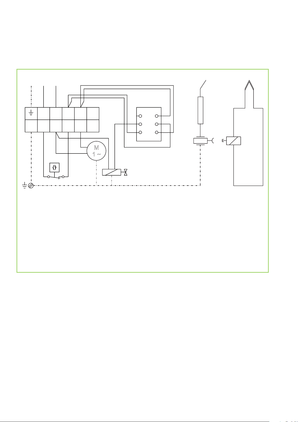
Electrical wiring diagram
PE L1 N
S
L1 N
5 4
STB
3
2 1
KL
3
2 16
A3
A2
A1
M
1 ~
B6
B5
B4
TE
Z
TMV
PZ
C
1
Legend:
KL
= Terminal block
M = Fan motor
MV = Solenoid valve
PZ = Piezo igniter
MV
S = Operating switch
STB = Safety temperature limiter
TE = Thermocouple
TMV = Safety pilot (thermo-electric gas valve)
Z = Ignition electrode
22

23

REMKO QUALITY WITH SYSTEMS
Air-Conditioning | Heating | New Energies
Telephone +49 (0) 5232 606-0
Telefax +49 (0) 5232 606-260
E-mail info@remko.de
URL www.remko.de
REMKO GmbH & Co. KG
Klima- und Wärmetechnik
Im Seelenkamp 12
32791 Lage
Hotline within Germany
+49 (0) 5232 6 06-0
Hotline International
+49 (0) 5232 606-130
We reserve the right to make technical changes, and provide no guarantee as to the accuracy of this data!
 Loading...