How it Works
Log In / Sign Up
Buy Points
How it Works
FAQ
Contact Us
Questions and Suggestions
Users
Quectel Wireless Solutions
Loading...
#
201202M10
201202M35
201202M95
201211M50
201312UC20
201403GC10
201403GC65
201404UC15
201404UC15M
201408UG95
201508UG96
201510UC20
201511M85
201512M95
201603EC20
201604M26
201605EC25A
3
201605M35
201606EC21A
201607EC25V
4
201609EC21V
201609MC20
201609MC60
201703FC20
201703FC20N
201705BG96NA
201706SC20A
2
201707BG96
2
201708EC21E
201708EC25E
201709SC20W
201805EC21AU
201805EC25AU
2
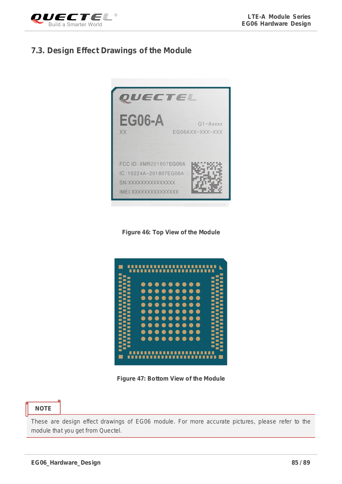
201807EG06A
201807EG95NA
201808BC66
201808EC25AF
201901BG96M
201901EM12G
201902M66
201903EG25G
201903EG61NA
201903EG91NS
201905AG35LA
201905AG35NA
201905SC66MW
201906EG21G
2
201906EM06A
201907AG35E
201907BC66NA
201907EC25MX
201907EG91VX
201909EC21AUX
2
201909EC25AFX
2
201909EG91NAX
201909EG95NAX
201910BG95M3
201911SC600WF
2019SC600NA
16182009001
16182009002
16182009003
16182009004
16182010001
16182010002
Loading...
Loading...
Nothing found
201807EG06A
Users Manual
97 pgs
1.6 Mb
0
Table of contents
Loading...
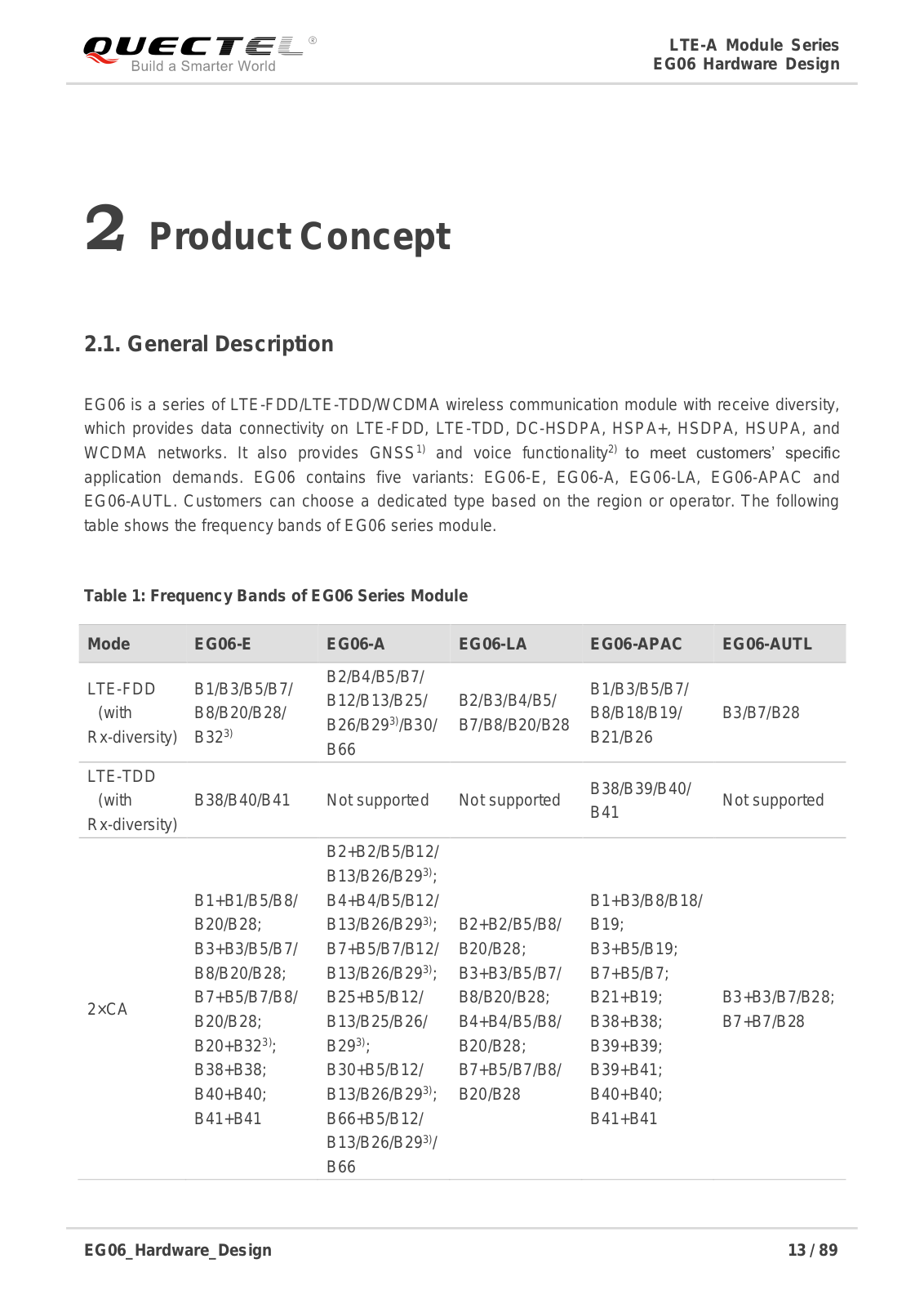
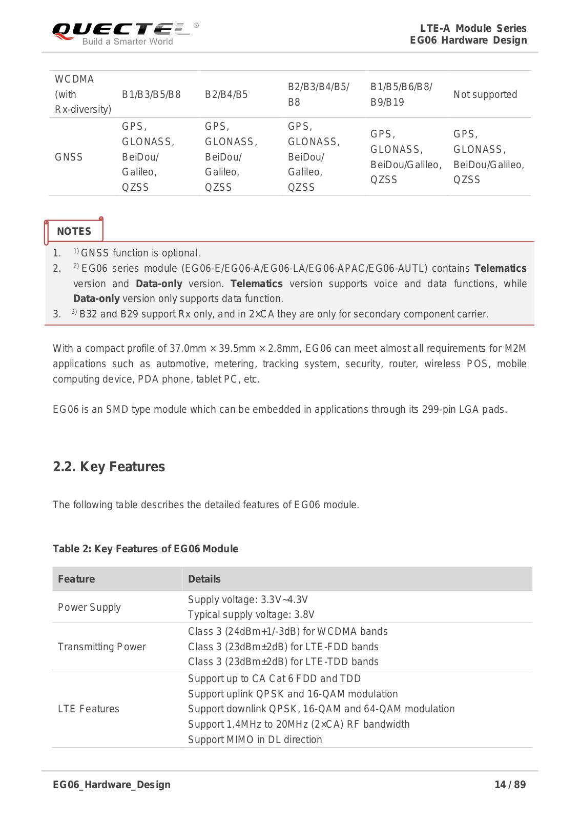
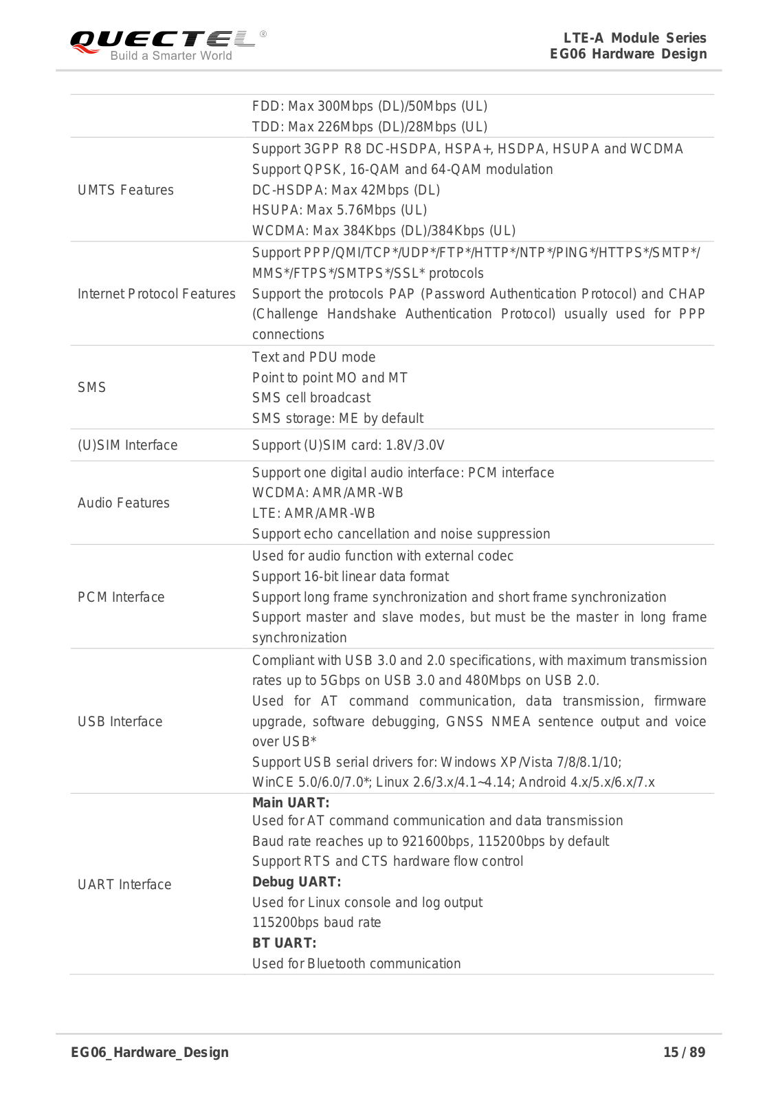
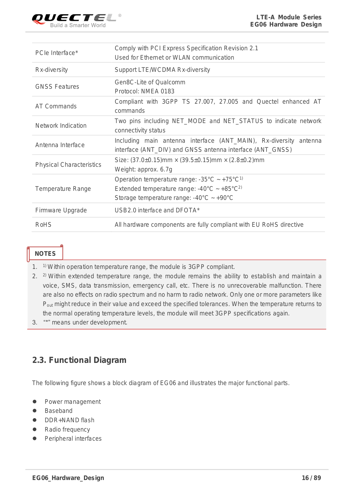
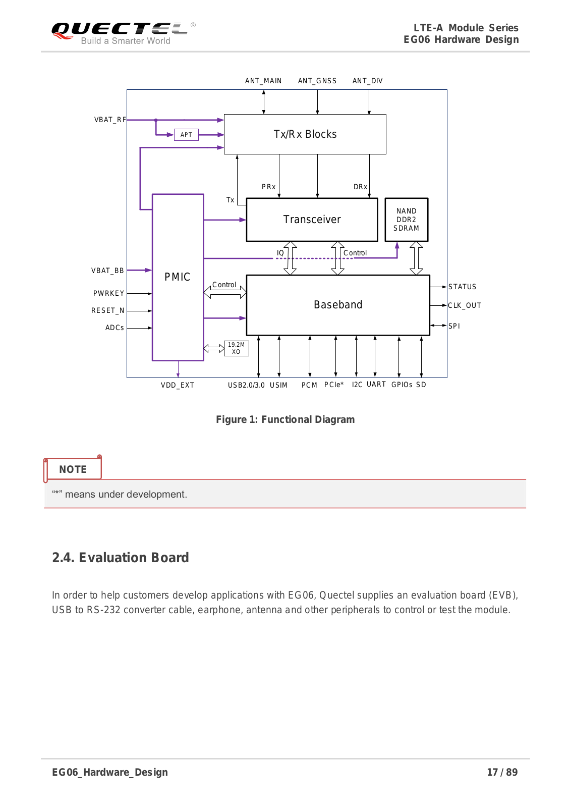
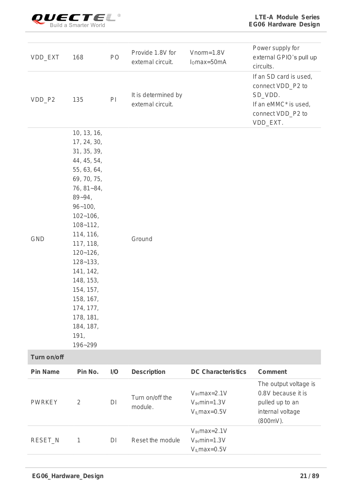
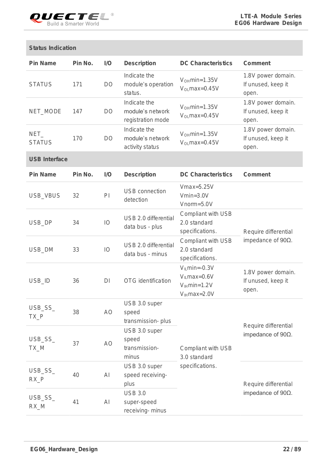
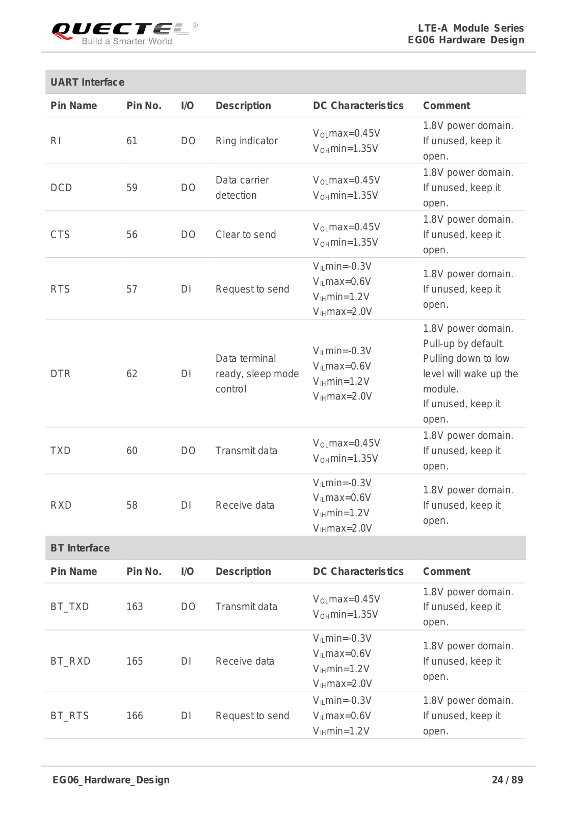
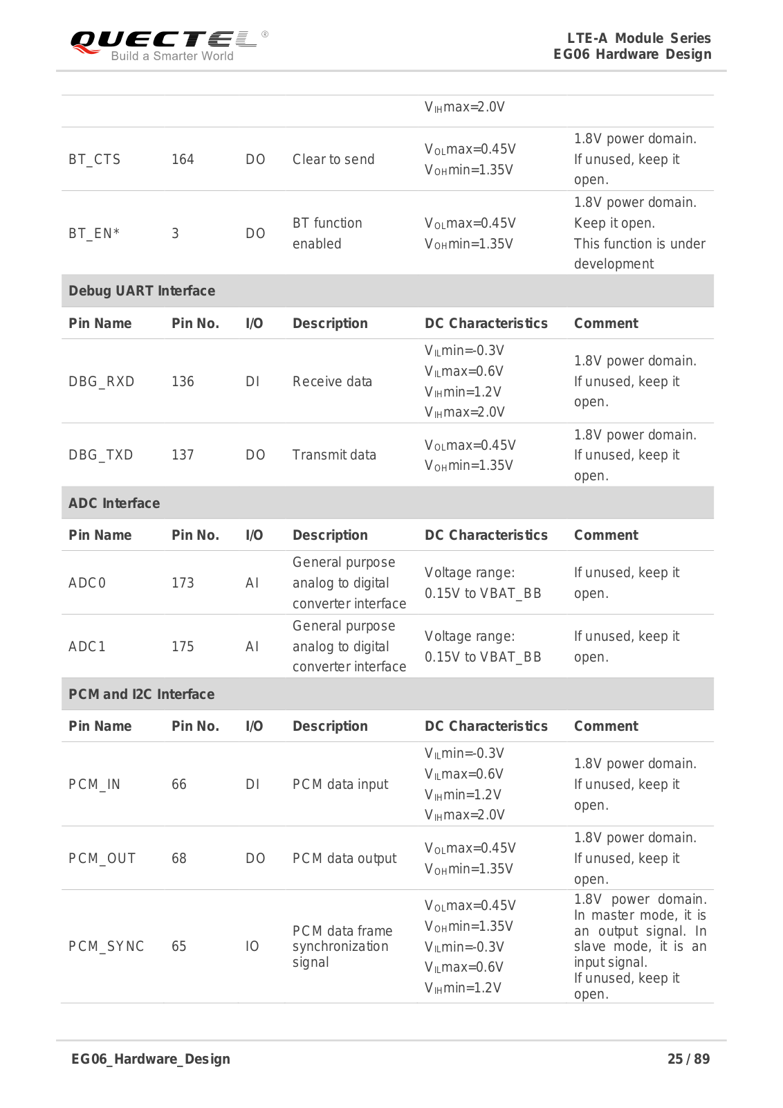
Quectel Wireless Solutions 201807EG06A Users Manual
...
Quectel Wireless Solutions Users Manual
Download
Specifications and Main Features
Frequently Asked Questions
User Manual
Download
Loading...
+
hidden pages
Unhide
You need points to download manuals.
1 point = 1 manual.
You can buy points or you can get point for every manual you upload.
Buy points
Upload your manuals