


SC20-A Manual
LTE Module Series
Rev: SC20-A_Manual_R1.0
Date: 2017-06-30
www.quectel.com

Our aim is to provide customers with timely and comprehensive service. For any
assistance, please contact our company headquarters:
Quectel Wireless Solutions Co., Ltd.
7th Floor, Hongye Building, No.1801 Hongmei Road, Xuhui District, Shanghai 200233, China
Tel: +86 21 5108 6236
Email: info@quectel.com
Or our local office. For more information, please visit:
http://www.quectel.com/support/salesupport.aspx
For technical support, or to report documentation errors, please visit:
http://www.quectel.com/support/techsupport.aspx
Or email to: Support@quectel.com
GENERAL NOTES
QUECTEL OFFERS THE INFORMATION AS A SERVICE TO ITS CUSTOMERS. THE INFORMATION
PROVIDED IS BASED UPON CUSTOMERS’ REQUIREMENTS. QUECTEL MAKES EVERY EFFORT
TO ENSURE THE QUALITY OF THE INFORMATION IT MAKES AVAILABLE. QUECTEL DOES NOT
MAKE ANY WARRANTY AS TO THE INFORMATION CONTAINED HEREIN, AND DOES NOT ACCEPT
ANY LIABILITY FOR ANY INJURY, LOSS OR DAMAGE OF ANY KIND INCURRED BY USE OF OR
RELIANCE UPON THE INFORMATION. THE INFORMATION SUPPLIED HEREIN IS SUBJECT TO
CHANGE WITHOUT PRIOR NOTICE.
COPYRIGHT
THE INFORMATION CONTAINED HERE IS PROPRIETARY TECHNICAL INFORMATION OF
QUECTEL CO., LTD. TRANSMITTING, REPRODUCTION, DISSEMINATION AND EDITING OF THIS
DOCUMENT AS WELL AS UTILIZATION OF THE CONTENT ARE FORBIDDEN WITHOUT
PERMISSION. OFFENDERS WILL BE HELD LIABLE FOR PAYMENT OF DAMAGES. ALL RIGHTS
ARE RESERVED IN THE EVENT OF A PATENT GRANT OR REGISTRATION OF A UTILITY MODEL
OR DESIGN.
Copyright © Quectel Wireless Solutions Co., Ltd. 2017. All rights reserved.
SC20-A_Manual_R1.0 Confidential / Released 1 / 49

About the Document
History
Revision Date Author Description
1.0 2016-06-29 Nina Dou SC20-A_Manual_R1.0
SC20-A_Manual_R1.0 Confidential / Released 2 / 49

Contents
About the Document ................................................................................................................................... 2
Contents ....................................................................................................................................................... 3
1 Introduction .......................................................................................................................................... 5
1.1. Safety Information...................................................................................................................... 5
2 Product Concept .................................................................................................................................. 7
2.1. General Description ................................................................................................................... 7
2.2. Key Features ............................................................................................................................. 8
2.3. Functional Diagram ................................................................................................................. 10
2.4. Evaluation Board ..................................................................................................................... 11
3 Application Interfaces ....................................................................................................................... 12
3.1. General Description ................................................................................................................. 12
3.2. Pin Assignment ........................................................................................................................ 13
4 Wi-Fi and BT ....................................................................................................................................... 14
4.1. Wi-Fi Overview ........................................................................................................................ 14
4.1.1. Wi-Fi Performance ......................................................................................................... 14
4.2. BT Overview ............................................................................................................................ 15
4.2.1. BT Performance ............................................................................................................. 15
5 GNSS ................................................................................................................................................... 17
5.1. GNSS Performance ................................................................................................................. 17
6 Antenna Interface ............................................................................................................................... 18
6.1. Main/Rx-diversity Antenna Interface ........................................................................................ 18
6.1.1. Pin Definition .................................................................................................................. 18
6.1.2. Operating Frequency ..................................................................................................... 18
6.2. Wi-Fi/BT Antenna Interface ..................................................................................................... 20
6.3. GNSS Antenna Interface ......................................................................................................... 20
6.4. Antenna Installation ................................................................................................................. 21
6.4.1. Antenna Requirement .................................................................................................... 21
7 Electrical, Reliability and Radio Characteristics ............................................................................ 23
7.1. Absolute Maximum Ratings ..................................................................................................... 23
7.2. Power Supply Ratings ............................................................................................................. 23
7.3. Charging Performance Specifications ..................................................................................... 24
7.4. Operating Temperature ............................................................................................................ 24
7.5. Current Consumption .............................................................................................................. 25
7.6. Electrostatic Discharge ............................................................................................................ 34
8 Technical Dimensions ....................................................................................................................... 35
8.1. Mechanical Dimensions of the Module.................................................................................... 35
8.2. Recommended Footprint ......................................................................................................... 37
SC20-A_Manual_R1.0 Confidential / Released 3 / 49

8.3. Top and Bottom View of the Module ........................................................................................ 38
9 Storage, Manufacturing and Packaging .......................................................................................... 39
9.1. Storage..................................................................................................................................... 39
9.2. Manufacturing and Welding ..................................................................................................... 39
9.3. Packaging ................................................................................................................................ 41
10 Appendix A GPRS Coding Schemes ............................................................................................... 43
11 Appendix B GPRS Multi-slot Classes .............................................................................................. 44
12 Appendix C EDGE Modulation and Coding Schemes ................................................................... 45
13 CE Requirement ................................................................................................................................. 46
14 IC & FCC Requirement ...................................................................................................................... 47
14.1. FCC Regulations: .................................................................................................................... 47
14.2. RF Exposure Information ......................................................................................................... 47
14.3. ISED Notice ............................................................................................................................. 47
14.4. ISED Radiation Exposure Statement ...................................................................................... 48
14.5. IMPORTANT NOTE: ................................................................................................................ 48
14.6. USERS MANUAL OF THE END PRODUCT: .......................................................................... 48
14.7. LABEL OF THE END PRODUCT: ........................................................................................... 49
SC20-A_Manual_R1.0 Confidential / Released 4 / 49

1
This document defines the SC20 module and describes its air interface and hardware interface which are
connected with your application.
This document can help you quickly understand module interface specifications, electrical and
mechanical details as well as other related information of SC20 module. Associated with application notes
and user guide, you can use SC20 module to design and set up mobile applications easily.
Introduction
1.1. Safety Information
The following safety precautions must be observed during all phases of operation, such as usage, service
or repair of any cellular terminal or mobile incorporating SC20 module. Manufacturers of the cellular
terminal should send the following safety information to users and operating personnel and to incorporate
these guidelines into all manuals supplied with the product. If not so, Quectel assumes no liability for the
customer’s failure to comply with these precautions.
Full attention must be given to driving at all times in order to reduce the risk of an
accident. Using a mobile while driving (even with a handsfree kit) causes
distraction and can lead to an accident. You must comply with laws and regulations
restricting the use of wireless devices while driving.
Switch off the cellular terminal or mobile before boarding an aircraft. Make sure it is
switched off. The operation of wireless appliances in an aircraft is forbidden, so as
to prevent interference with communication systems. Consult the airline staff about
the use of wireless devices on boarding the aircraft, if your device offers an
Airplane Mode which must be enabled prior to boarding an aircraft.
Switch off your wireless device when in hospitals or clinics or other health care
facilities. These requests are desinged to prevent possible interference with
sentitive medical equipment.
SC20-A_Manual_R1.0 Confidential / Released 5 / 49
Cellular terminals or mobiles operating over radio frequency signal and cellular
network cannot be guaranteed to connect in all conditions, for example no mobile
fee or with an invalid SIM card. While you are in this condition and need emergent
help, please remember using emergency call. In order to make or receive a call,
the cellular terminal or mobile must be switched on and in a service area with
adequate cellular signal strength.
Your cellular terminal or mobile contains a transmitter and receiver. When it is ON ,
it receives and transmits radio frequency energy. RF interference can occur if it is
used close to TV set, radio, computer or other electric equipment.
In locations with potencially explosive atmospheres, obey all posted signs to turn
off wireless devices such as your phone or other cellular terminals. Areas with
potencially exposive atmospheres include fuelling areas, below decks on boats,
fuel or chemical transfer or storage facilities, areas where the air contains
chemicals or particles such as grain, dust or metal powders, etc.
Please do not discard. Maybe wireless devices have an impact on the environment
so please do not arbitrarily discarded.
The device is restricted to indoor use only when oparating in the 5150 to 5350 Mhz
frequency range.
SC20-A_Manual_R1.0 Confidential / Released 6 / 49

2
Product Concept
2.1. General Description
SC20 is a series of 4G smart modules based on Qualcomm platform and Android operating system, with
providing industrial grade performance. It supports worldwide LTE-FDD/LTE-TDD/WCDMA/TD-SCDMA/
EVDO/CDMA/GSM coverage, and also supports short-range wireless communication via
Wi-Fi 802.11a/b/g/n and BT4.1 LE. Additionally, SC20 integrates GPS/GLONASS/BeiDou satellite
positioning systems. Due to multiple speech and audio codecs as well as the built-in high performance
AdrenoTM 304 graphics processing unit, it enables smooth play of 720P videos. The module also offers
multiple audio and video input/output interfaces as well as abundant GPIO interfaces.
The following table shows the supported network types and frequency bands of SC20.
Including a series of product such as:SC20-CE,SC20-A,SC20-AU,SC20-E,SC20-J.
Table 1: SC20-A Frequency Bands
Type Frequency
LTE-FDD B2/B4/B5/B7/B12/B13/B25/B26
WCDMA B1/B2/B4/B5/B8
GSM 850/1900MHz
Wi-Fi 802.11a/b/g/n
BT4.1 LE 2402-2480MHz
GNSS GPS/GLONASS/BeiDou
SC20 is an SMD type module, which can be embedded into applications through its 210-pin pads
including 146 LCC signal pads and 64 other pads. With a compact profile of 40.5mm × 40.5mm × 2.8mm,
SC20 can meet almost all requirements for M2M applications such as CPE,automotive, smart metering,
tracking, security, routers, wireless POS, mobile computing devices, PDA phone, tablet PC, etc.
2412-2472MHz;
5180-5825MHz
SC20-A_Manual_R1.0 Confidential / Released 7 / 49

2.2. Key Features
The following table describes the detailed features of SC20 module.
Table 2: SC20 Key Features
Feature Details
Applications Processor
Modem DSP
Memory 8GB EMMC+8Gb LPDDR3
Operating System Android OS 5.1
Power Supply
LTE Features
WCDMA Features
TD-SCDMA Features
ARM Cortex-A7 microprocessor cores (quad-core) up to 1.1 GHz
512KB L2 cache
QDSP6 v5 core up to 691.2 MHz
768KB L2 cache
Supply voltage: 3.5V~4.2V
Typical supply voltage: 3.8V
Support 3GPP R10 CAT4 FDD and TDD
Support 1.4 to 20 MHz RF bandwidth
Support DL 2 x 2 MIMO
FDD data rate: Max 150Mbps (DL), 50Mbps (UL)
TDD data rate: Max 130Mbps (DL), 35Mbps (UL)
Support 3GPP R8 DC-HSPA+
Support 16-QAM, 64-QAM and QPSK modulation
3GPP R6 HSUPA: Max 5.76Mbps (UL)
3GPP R8 DC-HSPA+: Max 42Mbps (DL)
Support CCSA Release 3
Max 4.2Mbps (DL), 2.2Mbps (UL)
CDMA Features Max 3.1Mbps (DL), 1.8Mbps (UL)
GPRS
Support GPRS multi-slot class 33
GSM/GPRS/EDGE
Data Features
WLAN Features
Bluetooth Feature BT4.1 LE
SC20-A_Manual_R1.0 Confidential / Released 8 / 49
Coding scheme: CS-1, CS-2, CS-3 and CS-4
Maximum of four Rx time slots per frame
EDGE
Support EDGE multi-slot class 33
Support GMSK and 8-PSK
Support 2.4G and 5G frequency band, (SC20-CE does not support 5G
frequency).
Support 802.11a/b/g/n, data rate up to 150Mbps
Support AP mode;

GNSS Features GPS/GLONASS/BeiDou
Text and PDU mode
SMS
Point to point MO and MT
SMS cell broadcast
SMS storage: ME by default
AT Commands
LCM Interface
Camera Interface
Audio Interface
USB Interface
Compliant with 3GPP TS 27.007, 27.005 and Quectel enhanced AT
commands
4 lanes MIPI_DSI, up to 1.5Gbps each
Support WVGA (2 lanes MIPI_DSI), up to 720p (4 lanes MIPI_DSI)
24bit color depth
Use MIPI_CSI, up to 1.5Gbps per lane, support two cameras
2-lane MIPI_CSI for rear camera, up to 8MP
1-lane MIPI_CSI for front camera, up to 2MP
Audio input
2 groups analog microphone input, integrate internal bias voltage
Audio output
Class AB stereo headphone output
Class AB earpiece differential output
Class D speaker differential amplifier output
Compliant with USB 2.0 specification; the data transfer rate can reach
up to 480Mbps
Used for AT command communication, data transmission, software
debugging and firmware upgrade
Support USB OTG (Need additional 5V power supply chip)
USB Driver: Support Windows XP, Windows Vista, Windows 7,
Windows 8, Windows CE5.0/6.0*, Linux 2.6/3.0, Android 2.3/4.0/4.2
USIM Interface
2 groups of USIM interface
Support USIM/SIM card: 1.8V, 3.0V
2 groups of UART interface
UART Interface
4-wire UART interface with RTS and CTS hardware flow control
2-wire UART interface for software debugging
Baud rate up to 4Mbps
SDIO Interface
Support SD3.0; 4bit SDIO; SD Card
Support hot plug
I2C Interface 3 groups I2C, used for TP, camera, sensor peripherals, etc.
ADC Interface
Support 3 ADC interfaces,used for input voltage sense, battery
temperature detection and general purpose ADC
Real Time Clock Implemented
Antenna Interface MAIN antenna, DRX antenna, GNSS antenna and Wi-Fi/BT antenna
Physical Characteristics
Size: 40.5±0.15 × 40.5±0.15 × 2.8±0.2 mm
Interface: LCC
SC20-A_Manual_R1.0 Confidential / Released 9 / 49

Weight: approx. 9.6g
Temperature Range
Operating temperature range: -35°C~+65°C 1)
Extended temperature range : -40°C~+75°C 2)
Firmware Upgrade Over USB interface
RoHS All hardware components are fully compliant with EU RoHS directive
NOTES
1)
Within operation temperature range, the module is 3GPP compliant.
2)
Within extended temperature range, the module remains the ability to establish and maintain a voice,
SMS, data transmission, emergency call, etc. There is no unrecoverable malfunction. There are also no
effects on radio spectrum and no harm to radio network. Only one or more parameters like Pout might
reduce in their value and exceed the specified tolerances. When the temperature returns to the normal
operating temperature levels, the module will meet 3GPP compliant again.
* means this feature is under development.
2.3. Functional Diagram
The following figure shows a block diagram of SC20 and illustrates the major functional parts.
Power management
Radio frequency
Baseband
LPDDR3+EMMC flash
Peripheral interface
--USB interface
--USIM interface
--UART interface
--SDIO interface
--I2C interface
--ADC interface
--LCD (MIPI) interface
--TP interface
--CAM (MIPI) interface
--AUDIO interface
SC20-A_Manual_R1.0 Confidential / Released 10 / 49
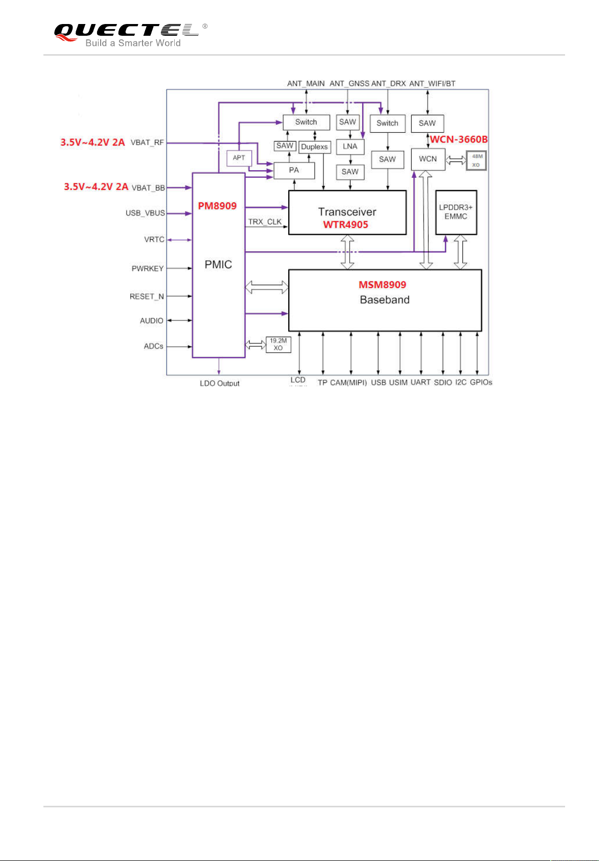
Figure 1: Functional Diagram
2.4. Evaluation Board
In order to help you to develop applications with SC20, Quectel supplies an evaluation board
(SMART-EVB), RS-232 to USB cable, USB data cable, power adapter, earphone, antenna and other
peripherals to control or test the module. For details, please refer to document [1].
SC20-A_Manual_R1.0 Confidential / Released 11 / 49

3
Application Interfaces
3.1. General Description
SC20 is equipped with 146-pin 1.0mm pitch SMT pads plus 64-pin ground pads and reserved pads that
can be embedded into cellular application platform. The following chapters provide the detailed
description of pins/interfaces listed below.
Power supply
VRTC interface
LCM interface
TP interface
Camera interface
Audio interface
USB interface
USIM interface
UART interface
SDIO interface
I2C interface
ADC interface
SC20-A_Manual_R1.0 Confidential / Released 12 / 49
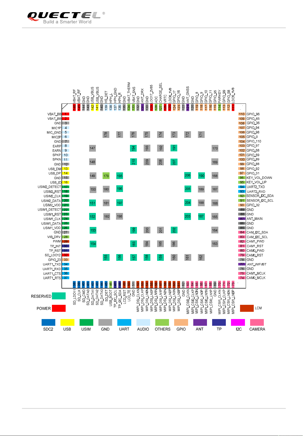
3.2. Pin Assignment
The following figure shows the pin assignment of SC20 module.
Figure 2: Pin Assignment (Top View)
SC20-A_Manual_R1.0 Confidential / Released 13 / 49
4
SC20 module provides a shared antenna interface ANT_WIFI/BT for Wi-Fi and Bluetooth (BT) functions.
The interface impedance is 50Ω. External antennas such as dipole antenna can be connected to the
module via the interface, so as to achieve Wi-Fi and BT functions.
Wi-Fi and BT
4.1. Wi-Fi Overview
SC20 module supports 2.4G and 5G double-band WLAN wireless communication based on IEEE 802.11
a/802.11b/ 802.11g/ 802.11n standard protocols. The maximum data rate is up to 150 Mbps.
The features are as below:
Support Wake-on-WLAN (WoWLAN)
Support ad hoc mode
Support WAPI SMS4 hardware encryption
Support AP mode
Support Wi-Fi Direct
Support MCS 0-7 for HT20 and HT40
NOTE
SC20-CE only supports 2.4G single band WIFI, and does not support 802.11a.
4.1.1. Wi-Fi Performance
The following table lists the Wi-Fi transmitting and receiving performance of SC20 module (SC20-CE
does not support 5G frequency band).
Referenced specifications are listed below:
No. Document
1
SC20-A_Manual_R1.0 Confidential / Released 14 / 49
IEEE 802.11n WLAN MAC and PHY, October 2009 + IEEE 802.11-2007 WLAN MAC and
PHY, June 2007

2
IEEE Std 802.11b, IEEE Std 802.11d, IEEE Std 802.11e, IEEE Std 802.11g, IEEE Std
802.11i: IEEE 802.11-2007 WLAN MAC and PHY, June 2007
4.2. BT Overview
SC20 module supports BT4.1 (BR/EDR+BLE) specification, as well as GFSK, 8-DPSK, π/4-DQPSK
modulation modes.
Supports max. 7 wireless connections.
Supports max. 3.5 piconets at the same time.
Supports one SCO (Synchronous Connection Oriented) or eSCO connection.
The BR/EDR channel bandwidth is 1MHz, and can accommodate 79 channels. The BLE channel
bandwidth is 2MHz, and can accommodate 40 channels.
Table 3: BT Data Rate and Version
Version Data rate Maximum Application Throughput Comment
1.2 1 Mbit/s >80 Kbit/s
2.0 + EDR 3 Mbit/s >80 Kbit/s
3.0 + HS 24 Mbit/s Reference 3.0 + HS
4.0 24 Mbit/s Reference 4.0 LE
Referenced specifications are listed below:
No. Document
1
2 Bluetooth Low Energy RF PHY Test Specification, RF-PHY.TS/4.0.0, December 15, 2009
Bluetooth Radio Frequency TSS and TP Specification 1.2/2.0/2.0 + EDR/2.1/2.1+ EDR/3.0/3.0
+ HS, August 6, 2009
4.2.1. BT Performance
The following table lists the BT transmitting and receiving performance of SC20 module.
Table 4: BT Transmitting and Receiving Performance
Transmitter Performance
SC20-A_Manual_R1.0 Confidential / Released 15 / 49
 Loading...