

Page 1

Remote Monitoring
Guide
DVR MODELS QR, QSDR & QSD9004
PC with Windows
Operating System
iPhone
Setup and Operating Guide for Remote Internet and Smartphone Monitoring,
MyQ-See DDNS, and Email Notification
Android
BlackBerry*
* Select Models
1
Page 2
Thank You for Choosing a Q-See Product!
This manual was accurate at the time it was completed. However, because of our ongoing
THANK YOU FOR PURCHASING THIS Q-SEE PRODUCT.
effort to constantly improve our products, along with smartphone and router manufacturers
EVERY EFFORT HAS BEEN MADE TO MAKE THIS DVR SIMPLE TO ASSEMBLE AND USE. HOWEVER, IF
adding and changing features on their products, it is possible that some functions may
YOU SHOULD RUN INTO ANY DIFFICULTIES DURING ITS INSTALLATION OR OPERATION, WE ARE HERE
FOR YOU.
change from how they are described. We encourage you to visit our website at www.Q-see.
com to check for the latest firmware and sofware updates as well as product announcements.
Throughout the manual we have highlighted warnings and other important information that will
assist you in operating your new system in a safe and trouble-free manner. Please take the
time to read and follow all instructions and pay attention to alerts as shown below:
TABLE OF CONTENTS
1. CONFIGURING THE DVR FOR REMOTE ACCESS 4
1.1 Network Settings 4
UPnP 5
DHCP 8
PPPoE 9
Static 10
1.2 Port Forwarding 12
1.3 DDNS (Dynamic Domain Name Service) 17
IMPORTANT! Red boxes with this icon indicate warnings. To prevent
possible injury or damage to the product, read all warnings before use.
NOTE! Text in blue boxes with the Information icon offer additional guidance
and explanations about how to make the most out of your system.
Every effort has been made to make this manual easy to understand and follow. However, if
you should run into any difficulties during any of these operations, we are here for you.
MAILING ADDRESS
Q-See Products
Digital Peripheral Solutions, Inc.
8015 E. Crystal Drive
Anaheim, CA 92807
PRODUCT SUPPORT, DOWNLOADS,
FIRMWARE UPDATES
& MANUALS
www.Q-See.com
CUSTOMER SUPPORT
FAX
714-998-3509
Live Chat at www.Q-See.com (M-F, 8-5 PST)
Email: cs@dpsi-usa.com
Phone: 877-998-3440 (M-F, 8-5 PST)
2. REMOTE MONITORING WITH A PC 19
2.1 Configuring Your Computer 19
2.2 Net-Viewer Software 25
Logging in to Net Viewer 25
Viewing Live and Recorded Video 26
Setup 27
PTZ Controls 31
3. E-MAIL NOTIFICATION SETUP 32
4. REMOTE MONITORING USING A SMARTPHONE 34
Android 35
BlackBerry 38
iPhone 44
Symbian 46
Windows Mobile 49
WEBSITE
www.Q-See.com
© 2011 Q-See. Reproduction in whole or in part without written permission is prohibited. All
rights reserved. This manual and software and hardware described herein, in whole or in part,
may not be reproduced, translated, or reduced to any machine-readable form without prior
written approval.
Trademarks: All brand names and products are trademarks or registered trademarks of their
respective owners.
Q-See is a registered trademark of DPS, Inc.
Disclaimer: The information in this document is subject to change without notice. The
manufacturer makes no representations or warranties, either express or implied, of any kind
with respect to completeness of its contents.
Manufacturer shall not be liable for any damages whatsoever from misuse of this product.
Rev. 1.1 3/24/2011
2 3
Page 3
CONFIGURING THE DVR FOR
Shut Down
CHAPTER 1
REMOTE ACCESS
1.1 NETWORK SETTINGS
The Network Setup menu options need to be configured in order to access the DVR remotely
over a network or the Internet. You will make the settings in the Network Setup menu.
NOTE! You must have a PC connected to the same router as the DVR before
proceeeding.
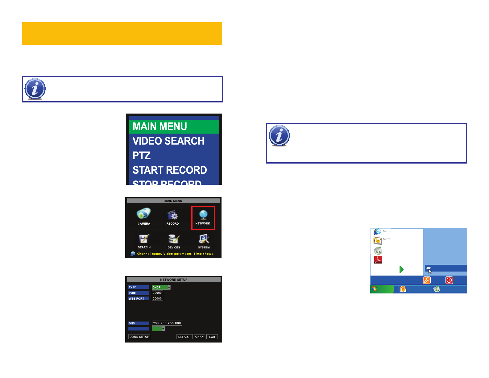
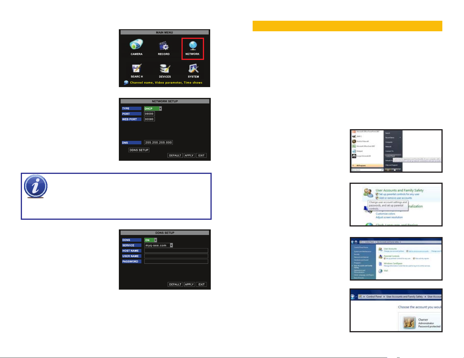
To access the Network Setup menu, rightclick with the mouse to bring up the Pop-Up
Menu. Select Main Menu.
PICTURE 1-1
Select NETWORK in the Main Menu
window.
UPNP
Universal Plug and Play, or UPnP for short, is a new set of networking protocols created by
consumer electronics manufacturers to allow easier connections of networked devices such
as computers, printers, mobile devices and network-capable security DVRs. Your DVR has
UPnP functionality built in which allows it to automatically seamlessly connect to a network,
obtain an IP address on that network and interact with other devices on the network - without
the need for special software or time-consuming configuration routines.
Things you will need to know :
1. The make and model of the router.
2. Whether your router supports UPnP
3. The IP address for the router.
4. You will be forwarding ports 80, 9000 and 18004.
NOTE! Check with your Router’s owner manual or the website of your
router’s manufacturer to determine whether it supports UPnP. If it does not,
then you will need to follow the instructions for Simple Port Forwarding as laid
out in Section 1.2. If you are still unsure about whether your router supports UPnP, you can
determine this by proceeding with Part 1, below.
PART 1: Accessing Your Router
You will need your router’s IP address in order to access it’s controls.
To locate the IP address of your router:
STEP 1. To access the router’s settings you will need to enter the Command (CMD)
panel on a computer also connected to the same router.
Microso Internet Explorer
A. WINDOWS XP – Select Run from
your Windows START menu (lower
left of screen) and type “cmd” after
the prompt.
PICTURE 1-2
Type can be set to UPnP, DHCP, PPPoE
or Static. For an automated configuration,
Microso Office Outlook 2007
iTunes
Adobe Acrobat
All Programs
start
start
Inbox Microsof... iTunes
PICTURE 1-4
Devices and Printers
Default Programs
Help and Support
Run
Log Off
select UPNP. To have the router assign the IP
address, use DHCP. To select the address,
use static. To attach directly to a modem
instead of using a router, use PPPoE.
UPNP OFF
PICTURE 1-3
4 5
Page 4
B. WINDOWS VISTA and WINDOWS
Devices and Printers
Default Programs
Help and Support
7 – Click on the START menu
(Windows icon) in the lower left of
your screen. Type “cmd” into the field
that says, “Search programs and
files” and hit ENTER or click on the
magnifying glass icon.
Microso Office Outlook 2007
Scky Notes
iTunes
Adobe Acrobat
All Programs
cmd
Shut down
PART 3: Activating UPnP in the DVR
STEP 6. On the DVR, access the
Network menu from the Main
menu.
STEP 7. Set Network Type to DHCP
and click ON next to UPNP.
UPNP ON
1
3 4
2
PICTURE 1-5
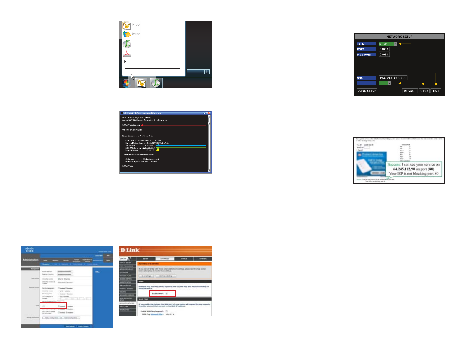
STEP 2. Type “ipconfig” at the prompt
(Red arrow in Picture 3) to access
router settings.
STEP 3. The “Default Gateway” (Yellow
arrow) is the IP address for your
router.
PICTURE 1-6
PART 2: Activating UPnP in the Router
STEP 4. Enter the router’s IP address into the address field in a web browser window.
This will open your router’s settings window.
STEP 5. Activate UPnP. Each manufacturer uses their own method for locating and
activating UPnP as shown by the red boxes in the example pictures below. Again, you
should consult your router’s manual or the manufacturer’s website for specifics.
STEP 8. Click on Apply and then OK
to save your settings before exiting
this menu.
PICTURE 1-9
STEP 9. Restart your DVR.
STEP 10. Check the status of ports 80,
9000 and 18004, by going to www.
canyouseeme.org and entering the
port numbers one at a time.
If you receive the “Success!”
message then you are ready to begin
remotely monitoring your DVR by
PICTURE 1-10
entering the IP address displayed by
CanYouSeeMe.
If you do not receive the “Success!” message, you should change the port number listed to
the right of Web Port (see Picture 1-9) from 80 to 85 or 89 in the Network Settings Menu
and begin again with Step 8.
PICTURE 1-7
PICTURE 1-8
6 7
Page 5
DHCP
When selecting DHCP as the Network type, the router automatically generates a DVR IP
address once the Network Setup menu is exited and the DVR is restarted.
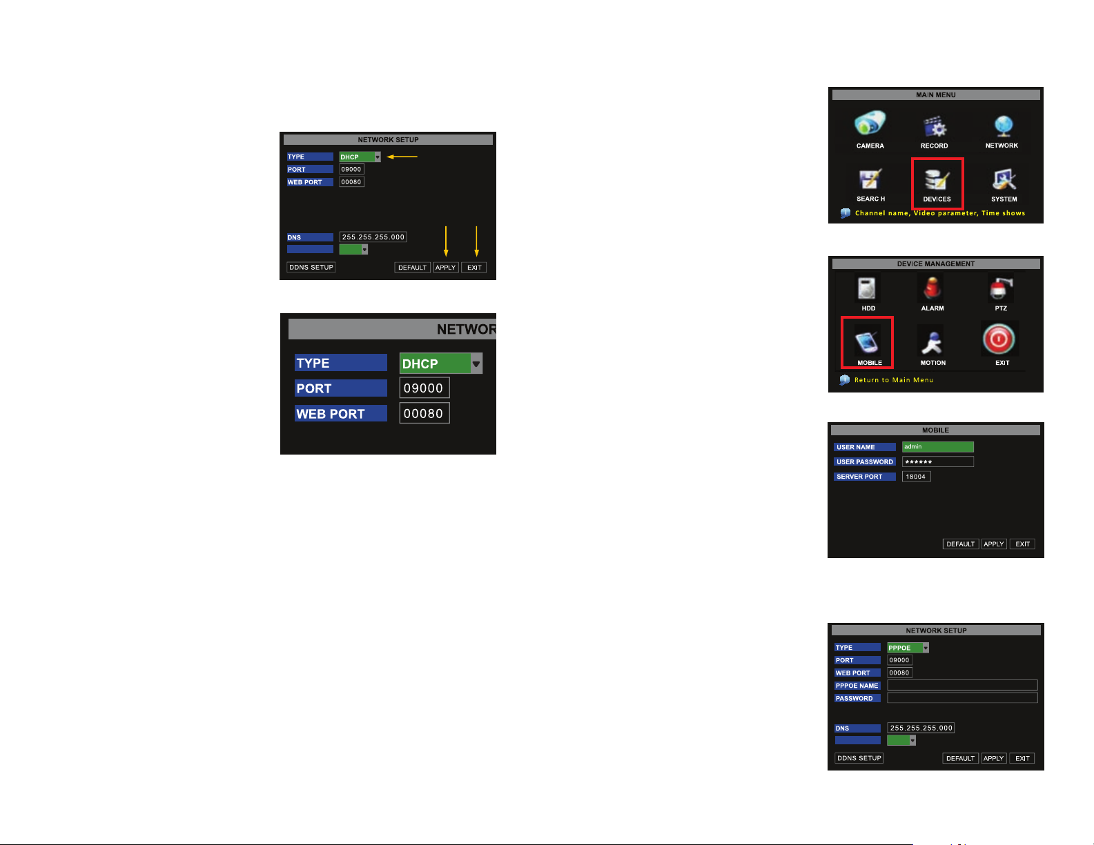
STEP 1. Select DHCP from the Type
drop-down menu,
STEP 2. Click on APPLY
STEP 3. Select EXIT.
STEP 4. Restart the DVR.
UPNP OFF
1
2 3
If you are going to access the DVR from a smart phone you will also need to go the Mobile
Setup and set up the DVR for smart phone access.
Go to the Main Menu and click on the
DEVICES icon.
PICTURE 1-13
PICTURE 1-11
Once the DVR has restarted, reopen the
Network Setup window and the IP address
of the DVR will now be listed.
Forward ports 80 and 9000 to this IP
address.
PICTURE 1-12
Write down this IP address. Then switch the Network Type to “Static” and re-enter the IP
address to avoid any discrepancies that might occur in the event the router auto generates a
different IP address in the future.
Then click on the MOBILE icon.
Enter the User Name and Password you
wish to use when accessing the DVR via a
smartphone.
Smartphones will access the DVR using port
18004. This port will need to be forwarded
along with ports 80 and 9000.
PPPOE
When selecting PPPoE as the Network type,
input the username and password provided
by your internet service provider. You would
use this option if you are attaching the DVR
directly to DSL or cable modem instead of a
router.
PICTURE 1-14
PICTURE 1-15
UPNP OFF
PICTURE 1-16
8 9
Page 6
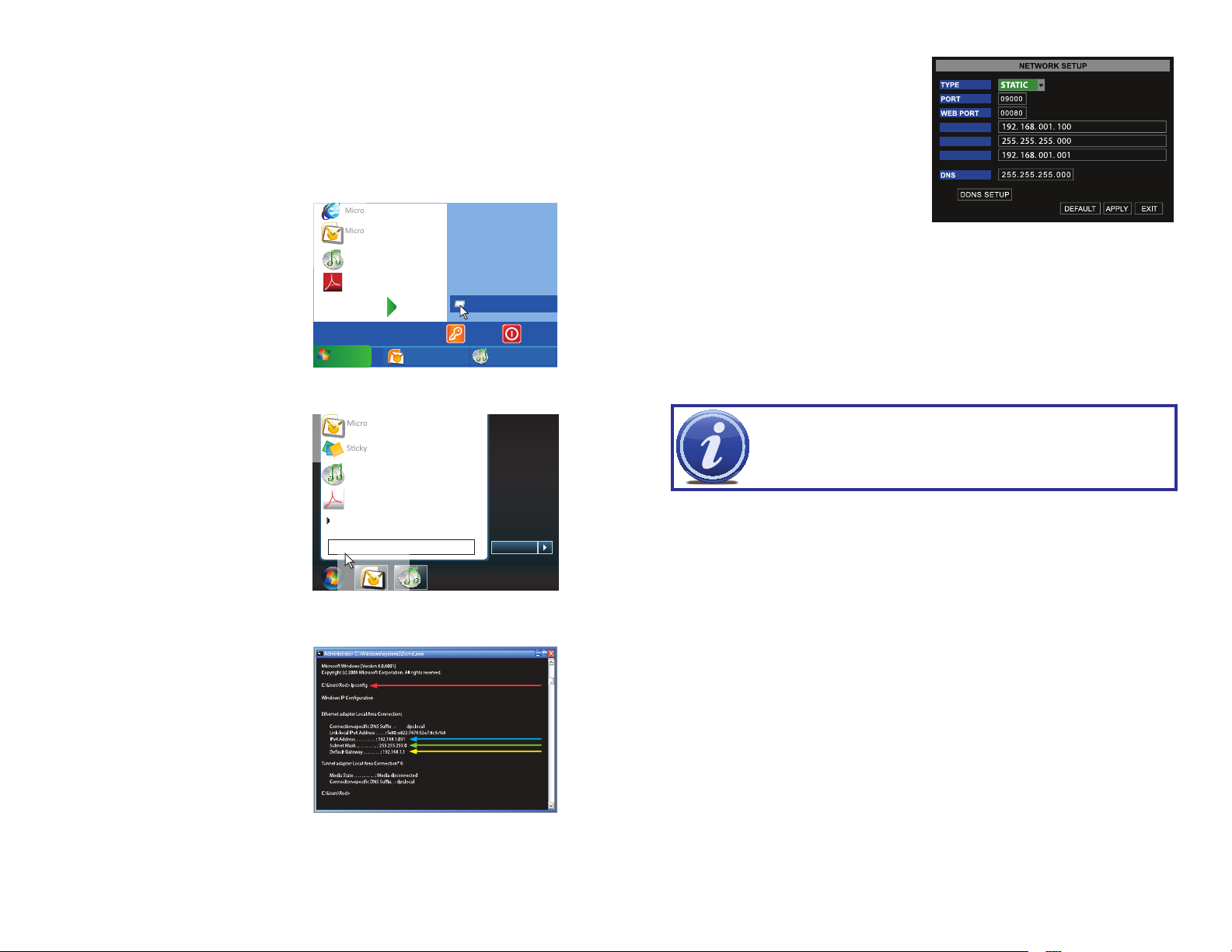
STATIC
Shut Down
Devices and Printers
Some DVRs are unable to automatically generate the IP address and supply it to the DVR.
Setting up a Static IP address accomplishes the same result as using DHCP in the previous
section, but it requires you to locate the information in the router yourself.
STEP 1. To access the router’s settings you will need to enter the Command (CMD)
panel on a computer also connected to the same router as the DVR.
A. WINDOWS XP – Select Run from
your Windows START menu (lower
left of screen) and type “cmd” after
the prompt.
Microso Internet Explorer
Microso Office Outlook 2007
iTunes
Adobe Acrobat
All Programs
start
start
Inbox Microsof... iTunes
PICTURE 1-17
Devices and Printers
Default Programs
Help and Support
Run
Log Off
STEP 4. Return to the Network window
on the DVR (Picture 1-20) and
enter the Subnet Mask and Gateway
numbers in the proper fields along
with the first three sets of numbers
from the IP4v address (Blue arrow
in Picture 1-19) into the IP Address
field.
To finish the IP address, you will need
to enter a fourth set of numbers that
is different than any other device
attached to the same router. If the
fourth set of numbers in your IP4v
address is a single or double-digit
number, then you can enter any
three-digit number up to 254. If, on
the other hand, the IP4v address
ended with a number in the 100s,
then enter a number between 200
and 254.
IP ADDRESS
NETMASK
GATEWAY
PICTURE 1-20
B. WINDOWS VISTA and WINDOWS
7 – Click on the START menu
(Windows icon) in the lower left of
your screen. Type “cmd” into the field
that says, “Search programs and
files” and hit ENTER or click on the
magnifying glass icon.
STEP 2. Type “ipconfig” at the prompt
(Red arrow in Picture 1-19) to
access router settings.
STEP 3. Write down the IP4v address
(Blue arrow) as well as the Gateway
and Subnet Mask numbers (Green
and yellow arrows).
Microso Office Outlook 2007
Scky Notes
iTunes
Adobe Acrobat
All Programs
cmd
PICTURE 1-18
PICTURE 1-19
Default Programs
Help and Support
Shut down
IMPORTANT! Do not use 255 or higher to complete your IP address as these
addresses are reserved for other devices and components.
STEP 5. Click Apply.
STEP 6. Click Exit.
10 11
Page 7
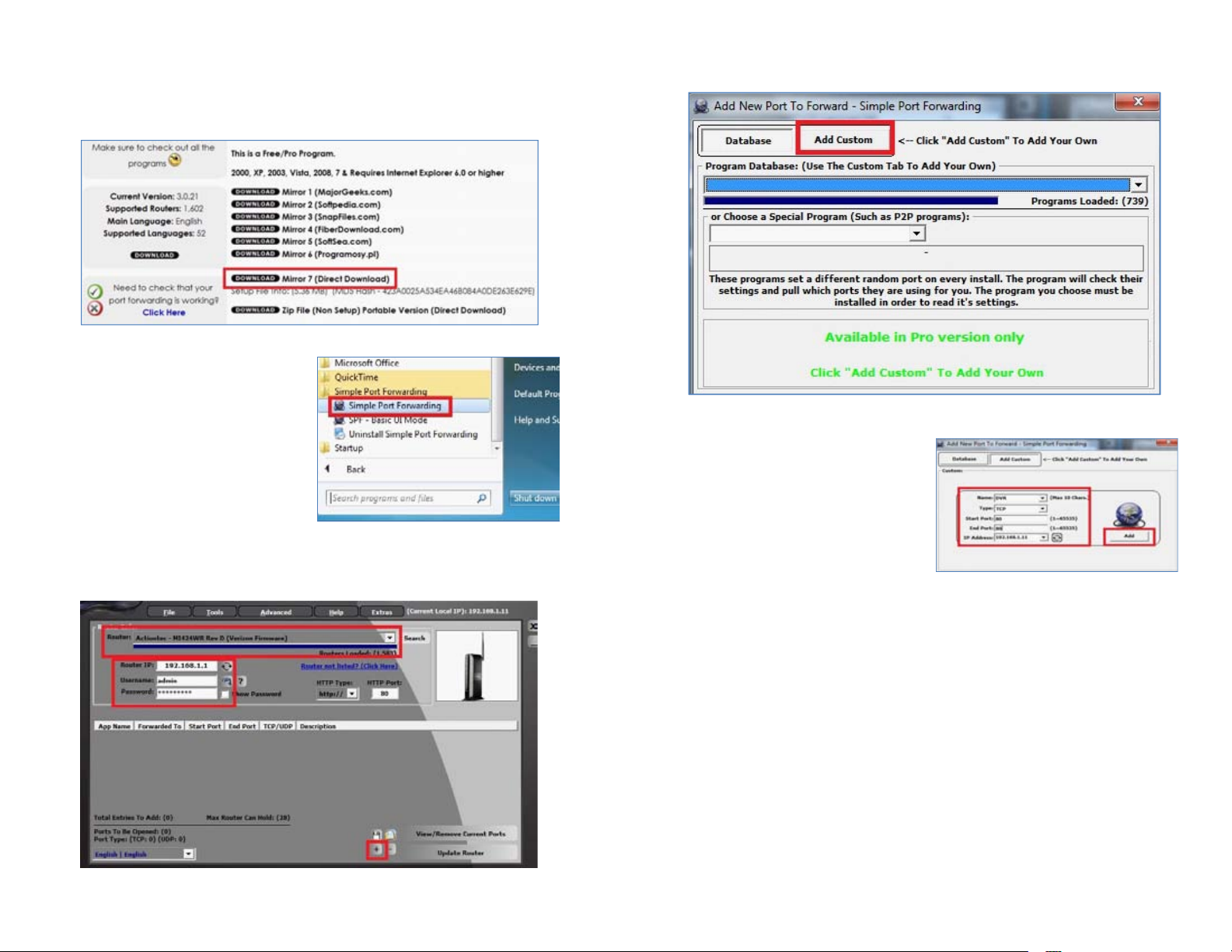
1.2 PORT FORWARDING
Download the FREE Simple Port Forwarding program from:
http://www.simpleportforwarding.com/download
Click on Download on Mirror 7 to download and install this program.
PICTURE 1-21
Once the program is installed, go to the
Windows Start Menu (Windows icon in
the lower left of your monitor) and look for
Simple Port Forwarding in the program list.
Click on the program to launch it.
PICTURE 1-22
Once Simple Port Forwarding has launched, select your router from the list. The default
Router IP and Login information will automatically come up. If you have previously changed
the login information, then you will have to enter it manually
Click on ADD CUSTOM.
PICTURE 1-24
Input the required information:
Name: (You can name your DVR if you wish)
Type: TCP
Start Port: 80
End Port:80
IP add: IP of DVR obtained in Network
Settings.
PICTURE 1-25
Click on ADD
Repeat for port 9000, and also for 18004 to allow smartphone access.
Click on “+” at the bottom to open the window allowing you to set your ports.
PICTURE 1-23
12 13
Page 8
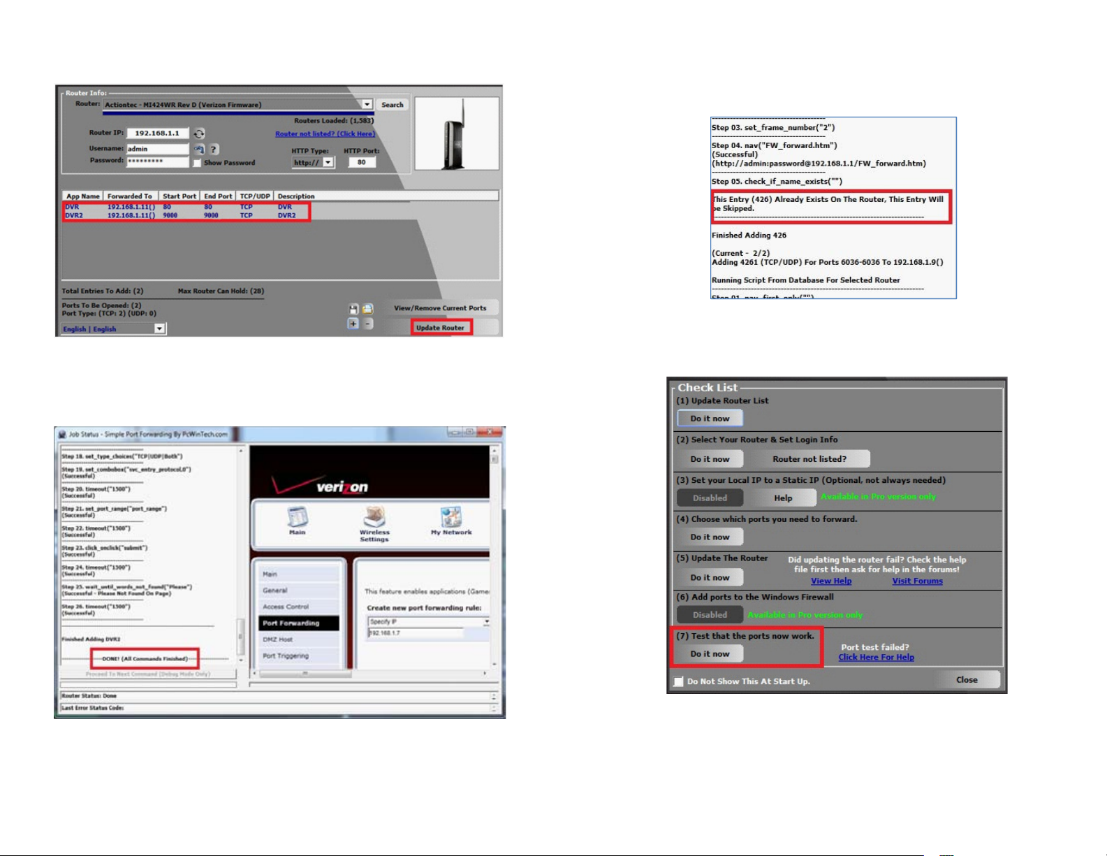
You will now be returned to the main window of the program. The ports you added will now
show on the list. Click on Update Router at the bottom.
PICTURE 1-26
You will see the “Updating is in progress” message. Please wait until you see it say DONE at
the bottom.
If for some reason, a port or ports that you forwarded are not listed in the Router and if you
see a message in the Scripts list on the left side of the window stating that the port already
exists (Red box in Picture 1-28), then you will need to change the Port 80 to 85 in the DVR
and start over again.
PICTURE 1-28
Once you receive the DONE message that the ports have been successfully forwarded, test
if the ports are working by clicking on item number 7 in the Check List - Test that the ports
now work.
PICTURE 1-29
PICTURE 1-27
14 15
Page 9
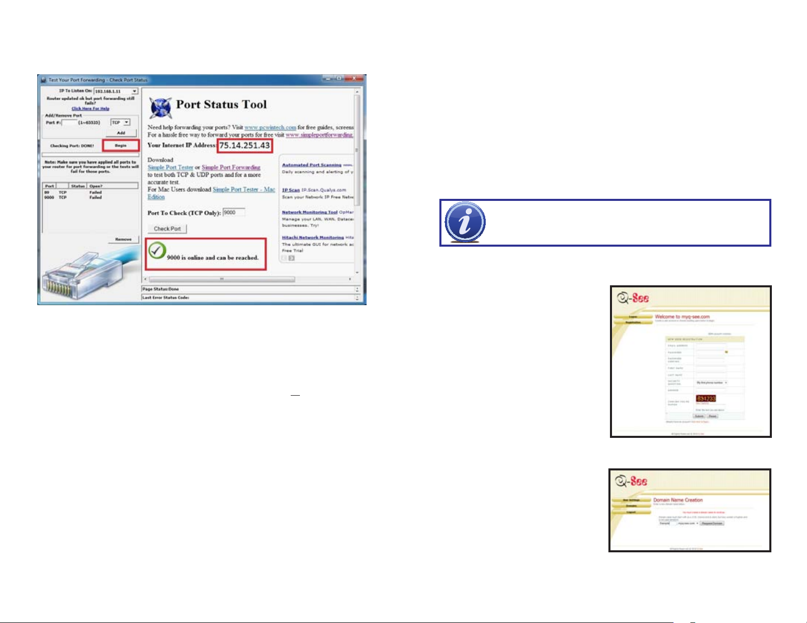
Click on Begin.
If you receive a message stating that the port is online and can be reached, then you have set
it up correctly.
PICTURE 1-30
To connect to your DVR from the Internet, you will need to put the Internet IP address shown
after “Your Internet Address:” message into the browser or access program window.
If you are forwarding any instead of port 80, then you need to put that port at the end of the
address.
1.3 DDNS (DYNAMIC DOMAIN NAME SERVICE)
You can access the DVR over the Internet using a static or dynamic IP address. However,
your service provider can change this dynamic address from time to time. When it changes,
you will have to return to repeat the steps in in Network Settings or by visiting www.
MyIPAaddress.com, again from a computer attached to the same router as the DVR to get
the new public IP address.
There are two solutions to this problem. The first would be to obtain a static IP address from
your ISP – which can be expensive. A second – and free – option is to use a dynamic domain
name service (DDNS) to get a domain name that can be linked to your dynamic IP address. In
addition to automatically keeping up with the changes in the address, you will now be able to
enter a domain name rather than a string of digits when accessing the DVR in Internet Explorer.
While there are multiple free DDNS services available, we recommend using www.MyQ-See.
com or www.DynDNS.com as the DVR has been already configured to accept account
information from these two services.
NOTE! Before setting up DDNS, you must have previously set up Port
Forwarding as described in the preceding section.
Setting up DDNS
The following instructions are for setting up DDNS with MyQ-See, instructions for DynDNS are
available on their website.
STEP 1. Using a computer that is
connected to the same router as the
DVR, use Internet Explorer to go to
www.MyQ-See.com
STEP 2. Fill out the required information
to register and click the Submit
button at the bottom of the screen.
Example: if you use port 85, you will need to enter: http://75.14.251.43:85
Instructions for using the ASee software on your smartphone can be found on the CD that
came with your DVR, or it can be downloaded by clicking on the links below:
Android: http://q-see.com/files/DeviceFiles/R-AndroidSetupNewweb.pdf
Blackberry: http://q-see.com/files/DeviceFiles/R-Smart Phone Access Blackberry.pdf
iPhone: http://q-see.com/files/DeviceFiles/R-Smart Phone Access iPhone.pdf
Symbian: http://q-see.com/files/DeviceFiles/R-Smart Phone Access Symbian.pdf
Windows Mobile:
http://q-see.com/files/DeviceFiles/R-Smart Phone Access Windows Mobile.pdf
STEP 3. The next page will ask you
to create a domain name. Domain
names must begin with a letter (a-z)
or a number (0-9) and cannot contain
a hyphen. Once you’ve decided
upon a name, click on the “Request
Domain” button. If it is available you
will see a confirmation screen along
with the IP address associated with it.
Confirm that this matches the number
obtained in Network Settings. Your
domain name will look like this:
http://example.myq-see.com
STEP 4. Once you have obtained your
domain name, you will need to
configure the DVR for access using it.
PICTURE 1-31
PICTURE 1-32
16 17
Page 10
To set up the DVR for access through a dynamic domain name:
STEP 1. Return to the Network window
in the Setting Menu.
REMOTE MONITORING WITH A PC
Once you have configured the network settings on the DVR to match those on your router
and forwarded the ports needed by the DVR to enable remote access over the Internet, you
will be ready to remotely view your cameras using a webcam program based on an ActiveX
control. For this to work, you will have to enable the ActiveX control options that are built into
Internet Explorer. It is strongly suggested that you be running the latest version of Internet
Explorer (currently IE8). The instructions below will describe the process using that version of
the browser. Instructions for users with IE6 or 7 are available in the Resources library of our
Technical Support page.
CHAPTER 2
PICTURE 1-33
STEP 2. In the Network window, click
on the DDNS Setup button to
generate a DDNS setting dialog box
(Picture 1-35)
PICTURE 1-34
NOTE! You will need to enter your Primary or Public DNS. This can be found
in your router status tab. To locate this, enter the Gateway address number
that appears in your Network Settings (or which you wrote down while setting
up Static IP) into a browser window on a computer that is connected to the
same router as your DVR. This will open your Router’s information window. Click on Status (or
the equivalent - each brand is different) to view your DNS numbers. You will only need the first.
If your router does not list the DNS address, you will need to call your Internet Service Provider.
STEP 3. Enter the User Name, Password
and Domain Name that you
registered for through http://myq-
see.com. Click the Apply button at
the bottom of the screen and then the
Exit button. This should return you to
the Network Setup menu.
2.1 CONFIGURING YOUR COMPUTER
USER ACCOUNT CONTROL FOR WINDOWS VISTA AND WINDOWS 7
Some users of computers using Windows Vista or Windows 7 operating systems may receive
an error message informing of a codec that is missing or not installed. This conflict can be
resolved by turning off User Account Control (UAC).
Windows Vista
STEP 1. Open the Control Panel
(accessible by clicking on the
Windows icon in the lower left of your
screen.
PICTURE 2-1
STEP 2. Select User Accounts and
Family Safety.
PICTURE 2-2
STEP 3. Select “Add or Remove User
Account.”
STEP 4. Click the Apply button and then
the Exit button at the bottom of the
Network Setup Screen and your
DDNS setup is complete.
You are now able to access the DVR remotely over the Internet by entering the domain name
into a browser window.
PICTURE 1-35
STEP 4. Select the desired user account.
PICTURE 2-3
PICTURE 2-4
18 19
Page 11

STEP 5. Select Turn User Account
Control on or off
STEP 6. Uncheck the box next to “Use
User Account Control (UAC) to help
protect your computer.”
STEP 7. You will then be asked to restart
your computer for the change to take
effect.
SETTING UP ACTIVEX CONTROL
STEP 1. Open Internet Explorer
STEP 2. Click on Tools
STEP 3. Select Internet Options in the
pull-down menu
PICTURE 2-5
PICTURE 2-9
STEP 4. Click on the Security Tab
STEP 5. Select Trusted Sites
STEP 6. Click on the Sites button
PICTURE 2-6
PICTURE 2-10
Windows 7
STEP 1. Open up the Start Menu
(accessible by clicking on the
Windows icon in the lower left of your
screen.
STEP 2. Type “uac” into the search bar
and hit ENTER. The User Account
Control will open or you will be offered
a link to click to open it.
STEP 3. Move slider to lowest setting
and press OK.
Microso Office Outlook 2007
Scky Notes
iTunes
Adobe Acrobat
All Programs
uac
PICTURE 2-7
Devices and Printers
Default Programs
Help and Support
Shut down
STEP 7. Uncheck the “Require server
verification (https:) for all sites in
this zone” button.
STEP 8. Type the DVR’s IP address
(obtained during Network Setup)
or DDNS domain name into the “Add
this website to the zone:” box.
STEP 9. Click the Add button
STEP 10. Close the window.
PICTURE 2-11
PICTURE 2-8
20 21
Page 12

STEP 11. Click the Custom level…
button.
STEP 13. Click the Reset button
STEP 14. Click “Yes” when asked, “Are
you sure you want to change the
setting for this zone?”
STEP 15. Click OK
STEP 16. Click Apply
STEP 17. Click OK
STEP 18. Close Internet Explorer
Security Settings - Trusted Sites ZoneSecurity Settings - Trusted Sites Zone
Settings
.NET Framework
Loose XAML
Disable
Enable
Prompt
XAML browser applications
Loose XAML
Disable
Enable
Prompt
XPS documents
Loose XAML
Disable
Enable
Prompt
*Takes effect after you restart Internet Explorer
Reset custom settings
Reset to:
Low
PICTURE 2-14
X
Reset...
OK
Cancel
STEP 12. Pull down the “Reset to:”
menu button and select Low
PICTURE 2-12
Security Settings - Trusted Sites ZoneSecurity Settings - Trusted Sites Zone
Settings
.NET Framework
Loose XAML
Disable
Enable
Prompt
XAML browser applications
Loose XAML
Disable
Enable
Prompt
XPS documents
Loose XAML
Disable
Enable
Prompt
*Takes effect after you restart Internet Explorer
Reset custom settings
Reset to:
Medium-high (default)
Medium-high (default)
Medium-low
Low
PICTURE 2-13
If you get a error message that says the program cannot load because the publisher is
unknown or the program is unsigned, return to the Tools setting in Internet Explorer.
X
Internet Properties
Open Internet Options, then go to the
“Advanced” tab (RED box in PICTURE
2-15), this will open the window in PICTURE
2-16.
Reset...
OK
Cancel
Internet Properties
Security
General
Home page
To create home page tabs, type each address on its own line.
Browsing history
Delete temporary files, history, cookies, saved passwords,
and web form information.
Search
Change search defaults.
Tabs
Change how webpages are displayed in
tabs.
Appearance
Colors
Content
Privacy
http://www.q-see.com
Delete browsing history on exit
Languages
OK
Connections AdvancedPrograms
Fonts Accessibility
Cancel
Use BlankUse DefaultUse Current
SettingsDelete...
Settings
Settings
Apply
X
?
PICTURE 2-15
22 23
Page 13

Scroll down to “Security”, and select the
options to “Allow software to run or install
even if the signature is invalid”, and
“Allow Active Content to Run Files on My
Computer” (RED box in PICTURE 2-16).
Internet Properties
Security
General
General Privacy Content Connections AdvancedPrograms
Security
Settings
Home page
To create home page tabs, type each address on its own line.
Security
Allow active content from CDs to run on My Computer*
Allow active content to run in files on My Computer*
Allow software to run or install even if the signature is invalid
Check for publisher’s certificate revocation
Check for server certificate revocation*
Check for signatures on downloaded programs
Browsing history
Do not save encrypted pages to disk
Delete temporary files, history, cookies, saved passwords,
Empy Temporary Internet Files folder when browser is clos
and web form information.
Enable DOM Storage
Enable Integrated Winsows Authentication*
Enable memory protection to help mitigare online attacks*
Enable native XMLHTTP support
Search
Enable SmartScreen Filter
Change search defaults.
*Takes effect after you restart Internet Explorer
Tabs
Change how webpages are displayed in
Reset Internet Explorer settings
tabs.
Resets Internet Explorer’s settings to their default
condition.
Appearance
You should only use this if your browser is in an unusable state.
Colors
Some settings are managed by your system administrator.
Content
Privacy
http://www.q-see.com
Delete browsing history on exit
Languages
OK
OK
Connections AdvancedPrograms
Restore advanced settings
Fonts Accessibility
Cancel
Cancel
Use BlankUse DefaultUse Current
SettingsDelete...
Settings
Settings
Reset...
Reset...
Apply
Apply
?
?
Internet Properties
Internet Properties
Internet Properties
PICTURE 2-16
To connect to the DVR from the remote computer you would then open an Internet Explorer
browser window and enter the internet IP of your router that you obtained earlier during
Network Setup.
NOTE! If you cannot use HTTP port 80 or 9000 because the port is being
used by another program, or it is being blocked by your service provider,
you can use another port in the same range. If you do so then you need to
forward the IP address of the router to the other port, change the port in the
DVR NETWORK settings, and you need to add the port number after the IP
address. For example, if you set the HTTP port as 82, you need to enter the IP address as
192.168.0.25:82. After you have forwarded the ports you can verify that the ports are open by
going to canyouseeme.org from a computer that is attached to the same router as the DVR.
X
X
2.2 NET-VIEWER SOFTWARE
LOGGING IN TO NET VIEWER
Prior to running the Net Viewer program, ensure your browser’s pop-up blockers are turned
off.
STEP 1. Open an IE Browser
window and input the IP address
and web port of your DVR (i.e.,
http://172.18.6.202/) into the address
bar to generate a Net Viewer User
Log-in screen.
STEP 2. Input the PASSWORD and
select NETWORK from the drop
down list.
STEP 3. Click on LOGIN and the Net Viewer program will show a live feed (below).
PICTURE 2-17
Once you are able to login, you will get the login screen, by default there is no password. Just push the
Login Button .
NOTE! If you are still experiencing problems connecting remotely, anti-virus programs
could also block the ActiveX control. Deactivate any anti-virus programs for the duration
of your remote monitoring sessin. Similarly, other plug-ins could also block ActiveX. Close
firewalls in Windows and in the router if applicable. Remember to restore your security
settings after exiting the monitoring session.
If you have a router plugged into another router, for example, if you have the DVR attached to
a router which is attached to DSL or Cable router, you may need to forward port 80 and 9000
(or whatever ports you are using) on the DSL or Cable router to the IP address of the router
that the DVR is attached to, so that router can then forward the port to the DVR. Please refer
The Net Viewer program allows full remote access and control of the DVR. It will automatically
display the live feed upon opening. The controls will replicate those found on the DVR itself.
NUMBER DESCRIPTION NUMBER DESCRIPTION
1 Menu Bar 2 PTZ Panning
3 PTZ View Controls 4 PTZ Preset Controls
5 - 9 Live Viewing Controls
PICTURE 2-18
Controls
to the PORT FORWARDING section above on how to get instructions on how to forward
the port on the other router.
24 25
Page 14

VIEWING LIVE AND RECORDED VIDEO
The Menu is located on the top left hand side of the screen. This toolbar includes selections
for LIVE, REPLAY, SETUP, and LOGOUT.
Live
This is the normal operating mode and is the mode that the program opens up to, showing
the live feed from any connected cameras.
SETUP
Selecting SETUP from the Net-Viewer toolbar will allow the configuration of the controls
for recording preferences, alarm preferences, PTZ controls and the network and system
settings. The various tabs within this Setup sub menu are RECORD, ALARM, PTZ CONTROL,
NETWORK, SETTING, and HOST INFO:
Record
The RECORD tab in the Setup menu, allows you to configure the recording status of the DVR
in a similar manner to the controls on the DVR itself.
Replay
Selecting REPLAY from the Net-Viewer
toolbar will allow you to replay previously
recorded footage. To find previously recorded
footage, select the date from the menu, a file
list will be displayed, choose the file from the
file list.
PICTURE 2-19
A set of buttons allows you to control playback and save the file for viewing on a computer.
Button Name Function
Play Button Play or pause recorded footage
Stop Button Stop playing recorded footage
F.F. Button Fast forward through recorded footage
Slow Button Decrease playback speed of recorded footage
Next Frame Playback recorded footage frame by frame
264 TO AVI Button Convert file from H.264 to AVI
Channel: Select ON or OFF from the drop
down menu next to each channel Resolution:
select the preferred resolution of the recorded
image
Quality: Select the preferred quality of the
recorded image
Audio: Select ON or OFF from the drop
down menu for the audio control if your
camera has audio capability.
Rec Mode: Select the recording mode from
the drop down menu. Select the ALWAYS
option to record 24 hours a day, or the TIME
RECORD option to record on a set schedule
or on motion detection.
Schedule: If you select the Time Record option, click on the Schedule button to set up the
schedule for when you want to record. This works the same as in the Record Setup function
in the DVR.
Default: This will restore all options to their original factory-installed settings.
Alarm
This allows you to configure the DVR’s alarm settings.
STEP 1. Select the channel(s) associated
with the camera(s) and configure all
options under that column
PICTURE 2-20
STEP 2. Configure each camera’s
sensor alarm settings by selecting the
desired option from the I/O ALARM
drop down menu.
• Select NO for normally opened
• Select NC for normally closed.
PICTURE 2-21
26 27
Page 15

STEP 3. To configure the DVR to detect motion:
• Select ON or OFF from the STATUS drop down menu to enable or disable motion
detection on each camera
• Select LOW, MEDIUM, HIGH, or HIGHEST from the SENSITIVITY drop down menu
to set the sensitivity of the motion detection
• Click SETUP for each camera next to MD AREA, which allows the definition of the
area to be detected for motion and when any object moves in the designated area,
recording will be triggered.
PTZ Control
The PTZ tab on the Setup menu allows the configuration of the PTZ camera options. Use
the following instructions to configure each PTZ camera. You will need to have your camera’s
manual at hand.
STEP 1. Select the channel(s) associated
with the PTZ camera(s) and configure
all options under that column
• On the area selection grid select each
square to enable motion detection
for each area. Squares will turn
red to indicate that motion will be
detected in that area. Recording
will not be triggered when motion
occurs in areas that have not been
selected.
PICTURE 2-22
The Video Loss option creates a notification if the system loses video feed for any reason,
such as camera damage, disconnected camera cables or a power supply malfunction.
• Select ON to generate an alarm buzzer when video loss occurs.
• Select OFF to turn this buzzer notification off.
The HDD Space pull down menu allows you to choose whether an alarm buzzer will sound
when the HDD is running low on available storage space.
• Select ON to enable the alarm buzzer.
• Select OFF to turn this buzzer notification off.
The HDD Loss option enables an alarm notification when the system has lost its connection
with the Hard Disk Drive, or if the drive has failed for some reason.
• Select ON to enable the alarm buzzer.
• Select OFF to turn this buzzer notification off.
STEP 2. From the PROTOCOL drop-
down menu, select Pelco-D or
Pelco-P, to match the settings on the
PTZ camera
STEP 3. Select the number from the ADDRESS drop down list, to match the settings on
the PTZ camera
STEP 4. From the BAUD RATE drop down menu, select 1200, 2400, 4800 or 9600, to
match the settings on the PTZ camera
STEP 5. From the DROP BIT drop down menu select the number to match the settings
on the PTZ camera
STEP 6. From the STOP BIT drop down menu select 1 or 2, to match the settings on the PTZ
camera
STEP 7. From the VERIFY drop down menu match the settings on the PTZ camera If
you have a verification setting on the control board then set this option to match it, if
you do not have this option on the PTZ camera control board then leave it set to OFF.
STEP 8. Repeat steps 2-7 for each PTZ camera connected to the DVR
STEP 9. Select APPLY to save settings before continuing to another tab.
PICTURE 2-23
The Alarm Manage option allows you to configure how long each sounding of the external
alarm (if any) and internal buzzer will continue. It also allows you to setup how long you want
the system to continue to record after the alarm ends (post record).
• Select 0 seconds, 10 seconds, 20 seconds, 40 seconds, or 60 seconds from
the Output drop down menu.
• Post Rec: This sets how long to record after the alarm ends, Select 0
seconds, 30 seconds, 1 minute, 2 minutes or, 5 minutes
The DEFAULT button will reset all Alarm options to their original factory installed settings
Select APPLY to save settings before continuing to another tab.
Select the DEFAULT button to reset all options to their original factory installed settings
Network
The NETWORK tab on the Setup menu allows you to view the network settings you made
in the DVR. Please see Section 1.1 Network Settings at the front of this guide for more
information.
28 29
Page 16

Setting
The SETTING tab on the Setup menu allows the control of the Net-Viewer program settings.
Internet Bandwidth - Select your system’s Internet bandwidth from the drop down menu. If
you are experiencing jerky playback, you may wish to choose a lower setting.
File Save Path - Select the path where video and still images taken from the DVR should be
saved on your computer.
IE Password Enable - This allows you to
require that users enter a password when
accessing the DVR from Internet Explorer. This
password can be different than those used
to access the DVR directly. Admin and User
passwords allow different levels of control over
the DVR.
DST - Turns on or off Daylight Savings Time.
Select the starting and ending dates and
times of Daylight Savings Time.
PICTURE 2-24
The DEFAULT button will reset all Alarm
options to their original factory installed
settings
PTZ CONTROLS
The PTZ controls operate in the same manner
as those on the DVR. For more information,
refer to PTZ Setup and PTZ Control on
pages 26 and 27 of the User Manual.
1
2
3
5
4
6
7
8
Select APPLY to save settings before
continuing to another tab.
Host Info
The HOST INFO tab on the Setup menu shows the remaining amount of space and
recording time on the HDD. It also shows the version of the Net Viewer software and lists the
MAC Address.
PICTURE 2-25
Logging Out of Net-Viewer
To log out of the Net-Viewer program, go to the main interface window and select LOGOUT
from the toolbar.
Item Name Function
1 PTZ Panning
Direction
2 Zoom, Focus
and Iris
3 Settings CUR Displays current action. Enter a preset’s number
LOAD Reloads the last saved setting
SAVE Saves the current setting
SET Choose from a preset
GOTO Goes to a specific preset
CLS Clears the currently running action
CRUISE Choose from a preset bit rate setting
4 Live Display Turns the Live Display On or Off
5 Screen Capture Captures a screen image and saves it to your PC
6 Record Record images to your DVR system from Net Viewer
7 Channel
Display Grid
8 Volume Control Adjust the volume if the camera is audio capable
Controls the panning direction of the PTZ Camera
Increase or decrease the zoom, focus or brightness of
the picture
manually in the accompanying box
Choose from full screen, 4-Channel, 8 Channel and
16-Channel view mode, depending on model.
PICTURE 2-26
30 31
Page 17

E-MAIL NOTIFICATION SETUP
Your DVR can be configured to notify you via e-mail when it detects motion. You will need to
set up an account which DVR can use to send out alerts before proceeding.
NOTE! Depending upon your settings, the system can generate a lot of e-mail
alerts. For that reason, we recommend setting up a dedicated e-mail address
specifically for the system to send alert notices. If you do not have your own
e-mail system (such as a corporate mail server) you should consider using a
free e-mail provider. However, because many free e-mail services allow only
a limited amount of e-mail traffic we specifically recommend using Google’s
Gmail service with its higher limit. Similarly, you will want the alert e-mails to go to a different
account than the one sending them. This will ease your management of these alerts. We
specifically recommend agains using Yahoo or Hotmail for this function as both services limit
the number of e-mails that can be sent out on a daily basis. Upon exceeding that limit, your
account will no longer send alerts for that time period.
For the example below, we will use Gmail. The settings can be found under Options when
logged into your Gmail account.
1. Make sure that the DVR’s firmware version is 090716 or newer
2. Make sure that your DVR has been set for network access and can be seen from
internet. This was covered in the first section of this guide, Configuring the DVR
for Remote Access.
3. If you have not already configured the DVR to record when it detects motion, you will
need to follow these instructions:
A. Go to MENU - DEVICES - MOTION. Turn on all the cameras and set to 2 or 3.
Click APPLY and EXIT
B. Go to MENU - RECORD and RECORD SET - TIME SCHEDULE and click on
SCHEDULE, then click on ALARM at the bottom (check mark), then schedule
which hours of which days will have the DVR looking for motion events. These
should not be for hours or areas which normally see traffic during the course of the
day. Click APPLY and EXIT.
The DVR will record on Motion now.
CHAPTER 3
5. Go to MENU - DEVICE - ALARM
- EMAIL SETUP: (Picture 3-2)
Example here for GMAIL account
(recommended), if you don’t have Gmail
account, go www.gmail.com and
sign up:
A. Turn ON email (Picture 3-3)
B. SSL : ON
C. Port : 00465
D. smtp: smtp.gmail.com
E. Send email: youremail@
gmail.com
F. Password: your password for
the gmail account
G. Recv email: use a different
e-mail address to receive
notifications.
H. Click APPLY - OK - EXIT
I. You should be back to Alarm
setting screen, click APPLY
- OK - EXIT.
There might be a delay (up to one hour) before the DVR begins to send e-mail.
If, after an hour, you still have not received an email notification, log into your Gmail account
and go to the Sent folder and to see whether an e-mail has been sent out. If you your
account shows that e-mails have been sent, go to your receiving e-mail account and check
the Junk or Spam folder to see if the e-mails have been diverted to that location.
NOTE! Some makes and models of routers do not provide a Public DNS address. In
such an instance, you should call your ISP to request that information.
PICTURE 3-2
PICTURE 3-3
4. Go to MENU - NETWORK, and on
DNS, you need to put your public
DNS. This number is shown in the
bottom of the network setting window
as shown in Picture 3-1.
PICTURE 3-1
TROUBLESHOOTING TIPS: If the above steps have been followed and there is still no
email being generated, please check the following:
1. What kind of router is connected to the DVR? If you have 2WIRE brand router, there
might be a problem with this router sending out email using a third party SMTP server.
You can try a different brand of router like Linksys or DLink or use your ISP SMTP
server.
2. If this DVR is located in a corporate office behind a firewall, it might not be allowed
to use a third party SMTP server. You will need to consult with your IT department
regarding setting up an e-mail account using your company’s SMTP server.
32 33
Page 18

REMOTE MONITORING USING
CHAPTER 4
A SMARTPHONE
This surveillance system can be configured to be viewed remotely from a 3G Smartphone.
This DVR is compatible with mobile phones running Windows Mobile Pro, Symbian and
Android operating systems, along with the iPhone, iPad, and some Blackberry models.
Before continuing, you should have already forwarded port 18004 as described in the Port
Forwarding section earlier in this guide.
On the DVR, go to Menu – Device – Mobile and enter the User name, Password and Port
number. The default settings are:
User name: admin
Password: admin
Server Port: 18004
ANDROID
1. Enter the Program function and
highlight the Market icon.
PICTURE 4-2
2. Launch the Market and the Market
interface will open.
PICTURE 4-1
You will also need to ensure that you are running the most recent version of the firmware on
the DVR. You may check this on the product page for your system at www.q-see.com
PICTURE 4-3
3. Click the Search icon on the upper
right corner and input “Asee” to
search for the Asee program.
PICTURE 4-4
4. Once you have located the program,
select it to begin the download
process.
PICTURE 4-5
34 35
Page 19

5. Follow the steps until the program is
downloaded and installed.
7. Once the program is open, it will go to
the main screen which includes the
controls for operating the DVR.
6. Clicking on Open once you receive
the “Application Installed” notification,
or clicking on the Asee icon in My
Programs will launch the program.
PICTURE 4-6
PICTURE 4-7
PICTURE 4-8
PICTURE 4-9
Item Function Item Function Item Function
1 PTZ Direction 2 Zoom+ - 3 Aperture
4 Focus+ - 5 Channel Select 6 Play & Pause
7 Full/Normal Screen 8 Snapshot (save to phone) 9 Setup
10 Change Channel Group 11 Help
8. Click on the Setup button (number 9)
to bring up the Settings Menu to
enter the network information needed
to access your DVR from the phone.
9. In the Settings Menu, you will enter
the same User Name, Password
and Port number that you entered
in the Mobile window on the DVR
along with the IP address obtained
when you first configured the DVR
for remote access along with the
IP address obtained when you first
configured the DVR for remote
access. The default settings are:
User name: admin
Password: admin
Server Port: 18004
PICTURE 4-10
Device Name is customizable to help you identify which DVR you are connecting to
You can push the History button in the upper right corner to view the IP addresses you have
used in the past.
36 37
Page 20

BLACKBERRY
Supported BlackBerry Models:
Curve 8900, Bold 9000 & 9700, Pearl 9100 & 9105, Tour 2 9650 and Onyx 9020.
1. Blackberry Desktop Manager needs to be installed on your PC. If you do not have this
you can download it from the Blackberry website. Then download the Blackberry
application file from the DVR product page on the Q-See website and extract it. You
will get a Asee.alx file.
2. Connect your phone to your PC via USB cable
3. Open the Desktop Manager
4. Click on Applications in the menu on
the left.
PICTURE 4-11
7. The ASee program will appear in your
list of applications. Click on Apply.
PICTURE 4-14
SETUP AND OPERATION ON THE BLACKBERRY PHONE VIEWER
1. The Blackberry viewer will be installed
to the Downloads directory.
5. Click the Import Files button in the
upper right.
6. Select the Asee.alx file and click on
Open.
2. Enter the Downloads directory, and
then click the ASee icon to launch
the program.
PICTURE 4-12
PICTURE 4-13
PICTURE 4-15
PICTURE 4-16
38 39
Page 21

3. When the program launches it will
open the main interface, the Live
Display, which will include the
controls for the DVR.
# Function
1 Connect/Disconnect
2 Full Screen
3 Snapshot
4 Setup
5 Help
6 Channel Selection
7 PTZ Control
PICTURE 4-17
A. Select the Network Type (3G or
WiFi) supported by the phone.
PICTURE 4-20
B. Click the Save button to save the
above setting, and system will return
back to Live display
4. In the Settings Menu, you will enter
the same User Name, Password
and Port number that you entered
in the Mobile window on the DVR
along with the IP address obtained
when you first configured the DVR
for remote access along with the
IP address obtained when you first
configured the DVR for remote
access. The default settings are:
User name: admin
Password: admin
Server Port: 18004
PICTURE 4-18
PICTURE 4-19
C. Click the History button to enter
into the History List.
D. Highlight one record and click
the Enter button to bring up the
pop-up menu. When selecting
the Open option, the system will
directly connect to the DVR and
will display Channel 1 by default.
E. When selecting the Edit option, the
system will allow you edit the history
record
PICTURE 4-21
PICTURE 4-22
PICTURE 4-23
40 41
Page 22

F. You can delete a record using the
Delete button.
6. Click the Full screen icon to enter
into full screen display mode. To quit
full screen mode, click the trackball
button again.
7. Click the the Next Page button to
reveal the PTZ Control icon. You are
now able to control the PTZ camera.
5. Click the Next Page icon to search
Channel options, and then choose
the channel you want to display.
PICTURE 4-23
PICTURE 4-24
PICTURE 4-25
8. Click the Help button to view the
software’s Help instruction.
9. Click the Close button to exit the
program.
PICTURE 4-26
PICTURE 4-27
42 43
Page 23
IPHONE
1: On your iPhone, go to the Apple
Appstore and Search for ASEE.
Download and install this program.
After finishing installation, the ASEE
icon (Picture 4-28) will appear in the
iPhone’s list of apps.
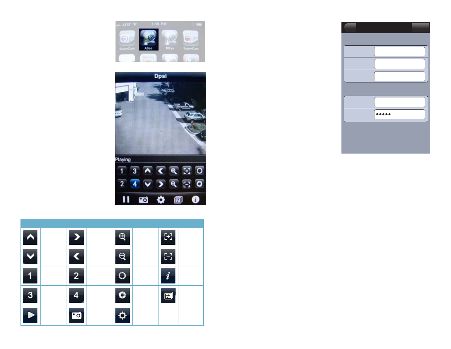
2: Launch the ASee application to open
the viewer and controls.
Operation is relatively straightforward with
the same controls as found on the DVR or in
remote monitoring.
PICTURE 4-28
3. When accessing this program for the
first time, or if you need to change
settings, click the Setings button to
open the Settings window. Enter
the same User Name, Password
and Port number that you entered
in the Mobile window on the DVR
along with the IP address obtained
when you first configured the DVR for
remote access. The default settings
are:
User name: admin
Password: admin
Server Port: 18004
Server Info
Name:
Address:
Port:
Account Info
User ID:
Settings
User
255.255.255.000
18004
admin
Password:
PICTURE 4-30
The History button will open a list of DVR IP addresses that you’ve accessed in the past.
HistoryBack
PICTURE 4-29
Button Function Button Function Button Function Button Function
PTZ Up PTZ Right Zoom In Focus In
PTZ Down PTZ Left Zoom Out Focus Out
CH 1 CH 2 Aperture
Open
CH 3 CH 4 Aperture
Close
Play/Pause Snapshot Settings
About
Next
Channel
Group
44 45
Page 24

SYMBIAN
1: You will need to copy the software
appropriate to which version of
Symbian you running - either
ASee_AL_3rd _0723.sisx or
ASee_AL_5th_0723.sisx to your
smartphone. Both are available on the
disk that came with your DVR or from
our website at www.Q-See.com.
2: Click on the ASee application to begin
the installation process.
4: Click the Continue button at the
pop-up prompt to allow the program
to utilize the network.
PICTURE 4-34
PICTURE 4-31
5: You will receive a confirmation
message when the software is
successfully installed.
3: Choose whether to install this program
in the phone’s internal storage or onto
a SD card.
PICTURE 4-32
6: If you installed the software onto the
SD card, you will find it located in the
Applications menu.
PICTURE 4-33
PICTURE 4-35
PICTURE 4-36
46 47
Page 25
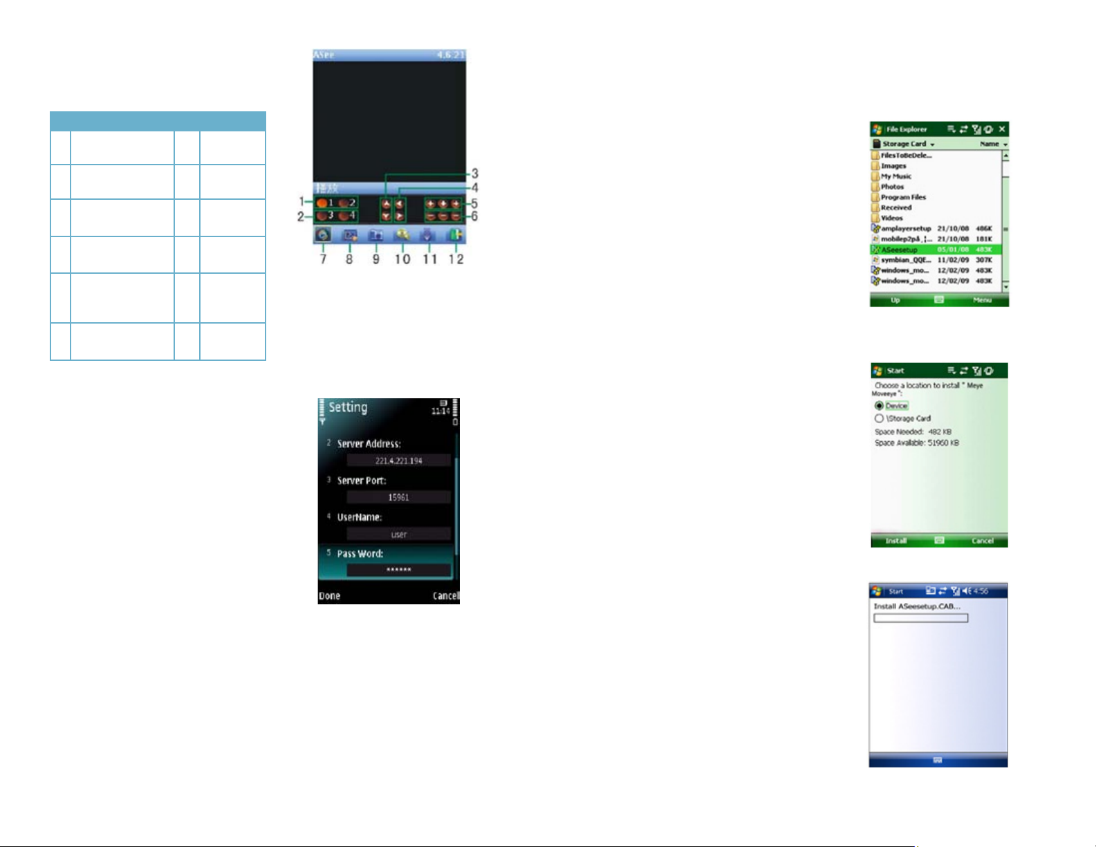
7: Click on the Asee icon to open the
program. It will open to the main
interface.
# Function # Function
1 Channels 1 & 2 7 Play &
Pause
2 Channels 3 & 4 8 Full/Normal
Screen
3 PTZ Direction
Left, Right
4 PTZ Direction
Up, Down
5 Zoom+ Focus +
Iris+
6 Zoom- Focus-
Iris -
8: When you access the program for
the first time, you will need to enter
the same User Name, Password
and Port number that you entered
in the Mobile window on the DVR
along with the IP address obtained
when you first configured the DVR
for remote access along with the
IP address obtained when you first
configured the DVR for remote
access. The default settings are:
User name: admin
Password: admin
Server Port: 18004
Default Access Point: Select your
network type based on your
current mobile net environment.
9 Snapshot
10 Setup
11 Next
Channel
Group
12 Quit
PICTURE 4-37
PICTURE 4-38
WINDOWS MOBILE
1. Copy the program named “Aseesetup.CAB” to your cellphone. It is included on the
disk that came with your DVR or it can be downloaded from your DVR’s product page
at www.Q-See.com
2. Once it has been loaded onto your
phone, click the program “Aseesetup”
to begin the installation process.
PICTURE 4-39
3. Choose to install the program on the
device rather than a storage card.
PICTURE 4-40
4. Click the Install button to start the
installation process.
9: Click Done to return to the main
screen.
The snapshot images will be saved to the defaultpath of “File manager\Images”.
PICTURE 4-41
48 49
Page 26
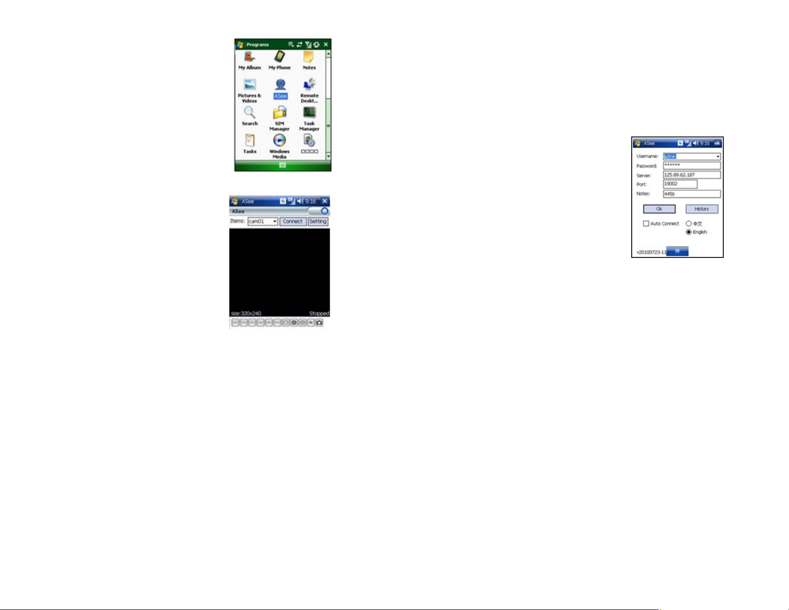
4. After the installation process has
finished, click on the ASee icon to
launch the program.
5. The program will launch and you are
ready to monitor your DVR using your
phone.
Select the channel you wish to monitor in the
pull-down menu at the top of your screen.
Click the Connect button to enter into the live
image of the channel you selected
Click the Settings button to set parameter of
the mobile viewer
The Function buttons in the bottom from left
to right in turn are:
PTZ Direction (left right, up down)
Zoom (zoom In, zoom out)
Focus Adjust (in, out)
Iris Adjust (open, close)
Snapshot
PICTURE 4-42
PICTURE 4-43
When accessing this program for the first time, or if you need to change settings, click the
Setup button to open the Settings window. Enter the same User Name, Password and Port
number that you entered in the Mobile window on the DVR. The default settings are:
User name: admin
Password: admin
Server Port: 18004
You can also select a channel which you wish to be your default starting channel.
Click OK to confirm the above setting, and
the application will return back to the previous
menu.
Auto-connect: When this is selected, the
mobile phone will automatically connect to
the DVR when the program is launched. Click
any area of screen to toggle display modes
between normal view and full screen.
The History button lets you view the IP
addresses you have used in the past.
PICTURE 4-44
You will need to ensure that you have the
right PTZ settings on the DVR before you
can control any PTZ cameras attached to
the device through your mobile phone. Ffor
details please refer to PTZ section of the DVR
User’s Manual.
Images captured using the Snapshot
feature will be saved to the default path
(Explorer/ Program/Files/Moveeye/Photo file).
50 51
Page 27

Digital Peripheral Solutions, Inc.
8015 E. Crystal Drive
Anaheim, CA 92807
52
 Loading...