

Page 1
PTQ-PDPMV1
Quantum Platform
PROFIBUS DP Master Network
Interface Module for Quantum
August 12, 2014
USER MANUAL
Page 2

Your Feedback Please
We always want you to feel that you made the right decision to use our products. If you have suggestions, comments,
compliments or complaints about our products, documentation, or support, please write or call us.
How to Contact Us
ProSoft Technology
5201 Truxtun Ave., 3rd Floor
Bakersfield, CA 93309
+1 (661) 716-5100
+1 (661) 716-5101 (Fax)
www.prosoft-technology.com
support@prosoft-technology.com
Copyright © 2014 ProSoft Technology, Inc. All rights reserved.
PTQ-PDPMV1 User Manual
August 12, 2014
ProSoft Technology ®, ProLinx ®, inRAx ®, ProTalk ®, and RadioLinx ® are Registered Trademarks of ProSoft
Technology, Inc. All other brand or product names are or may be trademarks of, and are used to identify products
and services of, their respective owners.
ProSoft Technology® Product Documentation
In an effort to conserve paper, ProSoft Technology no longer includes printed manuals with our product shipments.
User Manuals, Datasheets, Sample Ladder Files, and Configuration Files are provided on the enclosed CD-ROM in
Adobe® Acrobat Reader file format (.PDFs). These product documentation files may also be freely downloaded from
our web site: www.prosoft-technology.com
Page 3

Information for ProTalk® Product Users
The statement "power, input and output (I/O) wiring must be in accordance with Class I, Division 2 wiring methods
Article 501-10(b) of the National Electrical Code, NFPA 70 for installations in the U.S., or as specified in section 181J2 of the Canadian Electrical Code for installations within Canada and in accordance with the authority having
jurisdiction".
The following or equivalent warnings shall be included:
A Warning - Explosion Hazard - Substitution of components may Impair Suitability for Class I, Division 2;
B Warning - Explosion Hazard - When in Hazardous Locations, Turn off Power before replacing Wiring Modules,
and
C Warning - Explosion Hazard - Do not Disconnect Equipment unless Power has been switched Off or the Area is
known to be Nonhazardous.
D Caution: The Cell used in this Device may Present a Fire or Chemical Burn Hazard if Mistreated. Do not
Disassemble, Heat above 100°C (212°F) or Incinerate.
WARNING - EXPLOSION HAZARD - DO NOT DISCONNECT EQUIPMENT UNLESS POWER HAS BEEN
SWITCHED OFF OR THE AREA IS KNOWN TO BE NON-HAZARDOUS.
AVERTISSEMENT - RISQUE D'EXPLOSION - AVANT DE DÉCONNECTER L'ÉQUIPEMENT, COUPER LE
COURANT OU S'ASSURER QUE L'EMPLACEMENT EST DÉSIGNÉ NON DANGEREUX.
Warnings
North America Warnings
A Warning - Explosion Hazard - Substitution of components may impair suitability for Class I, Division 2.
B Warning - Explosion Hazard - When in hazardous locations, turn off power before replacing or rewiring modules.
Warning - Explosion Hazard - Do not disconnect equipment unless power has been switched off or the area is
known to be non-hazardous.
C Suitable for use in Class I, Division 2 Groups A, B, C and D Hazardous Locations or Non-Hazardous Locations.
ATEX Warnings and Conditions of Safe Usage
Power, Input, and Output (I/O) wiring must be in accordance with the authority having jurisdiction.
A Warning - Explosion Hazard - When in hazardous locations, turn off power before replacing or wiring modules.
B Warning - Explosion Hazard - Do not disconnect equipment unless power has been switched off or the area is
known to be non-hazardous.
C These products are intended to be mounted in an IP54 enclosure. The devices shall provide external means to
prevent the rated voltage being exceeded by transient disturbances of more than 40%. This device must be used
only with ATEX certified backplanes.
D DO NOT OPEN WHEN ENERGIZED.
Warnings
Electrical Ratings
Backplane Current Load: 1100 mA maximum @ 5 Vdc ± 5%
Operating Temperature: 0°C to 60°C (32°F to 140°F)
Storage Temperature: -40°C to 85°C (-40°F to 185°F)
Shock: 30 g operational; 50 g non-operational; Vibration: 5 g from 10 Hz to 150 Hz
Relative Humidity: 5% to 95% (with no condensation)
All phase conductor sizes must be at least 1.3 mm(squared) and all earth ground conductors must be at least
4mm(squared).
Page 4
CE
cULus
Shock & Vibration
CB Safety
GOST-R
RoHS
ATEX
CAUTION: THE CELL USED IN THIS DEVICE MAY PRESENT A FIRE
OR CHEMICAL BURN HAZARD IF MISTREATED. DO NOT
DISASSEMBLE, HEAT ABOVE 100°C (212°F) OR INCINERATE.
Maximum battery load = 200 μA.
Maximum battery charge voltage = 3.4 Vdc.
Maximum battery charge current = 500 μA.
Maximum battery discharge current = 30 μA.
Label Markings
<cULus>
E183151
Class I Div 2
Groups A,B,C,D T6
-30°C <= Ta <= 60°C
<Ex>
II 3 G
EEx nL IIc T6
-20°C <= Ta <= 60°C
Shock & Vibration tested to EN 60068 Standard
Agency Approvals and Certifications
Important Notice:
Page 5

PTQ-PDPMV1 ♦ Quantum Platform Contents
PROFIBUS DP Master Network Interface Module for Quantum User Manual
Contents
Your Feedback Please ........................................................................................................................ 2
How to Contact Us .............................................................................................................................. 2
ProSoft Technology® Product Documentation .................................................................................... 2
Information for ProTalk® Product Users .............................................................................................. 3
Warnings ............................................................................................................................................. 3
Warnings ............................................................................................................................................. 3
Important Notice: ................................................................................................................................. 4
Guide to the PTQ-PDPMV1 User Manual 11
1 Start Here 13
1.1 Hardware and Software Requirements ................................................................... 14
1.1.1 Quantum Hardware ................................................................................................. 14
1.1.2 PC and PC Software ............................................................................................... 14
1.2 Deployment Checklist .............................................................................................. 15
1.3 Installing ProSoft Configuration Builder Software ................................................... 16
1.4 Installing the Module ............................................................................................... 17
1.4.1 Installing the ProTalk Module in the Quantum Rack ............................................... 17
1.4.2 Connecting to the ProTalk Configuration/Debug Port ............................................. 18
1.4.3 PTQ-PDPMV1 Configuration / Debug Port Note .................................................... 19
2 Configuring the Module 21
2.1 Configuring the Module with ProSoft Configuration Builder .................................... 22
2.1.1 Setting Up the Project ............................................................................................. 23
2.1.2 Setting Module Parameters ..................................................................................... 25
2.1.3 Updating the Ethernet Settings ............................................................................... 32
2.2 Downloading the Ethernet Configuration to the Module ......................................... 33
2.3 Configuring the PROFIBUS Master ........................................................................ 34
2.3.1 Installing the GSD Files ........................................................................................... 35
2.3.2 Configuring the PROFIBUS Slaves ......................................................................... 36
2.3.3 Exporting the Processor Memory Map .................................................................... 50
2.3.4 Downloading the Project to the Module .................................................................. 53
2.3.5 Backing Up the Project ............................................................................................ 54
2.3.6 File Locations .......................................................................................................... 56
3 Configuring the Processor with Unity Pro 59
3.1 Importing the Functional Module ............................................................................. 60
3.1.1 Updating Checksum Values .................................................................................... 67
3.1.2 Setting Up General Unity Pro Project Settings ....................................................... 69
3.1.3 Configuring the Memory Size for the Processor ..................................................... 71
3.1.4 Building the Project ................................................................................................. 73
3.1.5 Downloading the Project to the Quantum Processor .............................................. 74
3.1.6 Verifying Communication between the Processor and the Module ........................ 75
3.2 Function Blocks Operation Overview ...................................................................... 79
3.3 Derived Function Blocks Overview ......................................................................... 82
ProSoft Technology, Inc. Page 5 of 306
August 12, 2014
Page 6

Contents PTQ-PDPMV1 ♦ Quantum Platform
User Manual PROFIBUS DP Master Network Interface Module for Quantum
3.3.1 Using the Derived Function Blocks ......................................................................... 82
3.4 Using Mailbox Function Blocks ............................................................................... 85
3.4.1 Overview ................................................................................................................. 85
3.4.2 Configuration........................................................................................................... 86
3.4.3 Trigger Bytes........................................................................................................... 87
3.4.4 Specific Input Pins .................................................................................................. 88
3.4.5 Specific Output Pins ............................................................................................... 88
3.5 Mailbox Overview ................................................................................................... 91
3.5.1 Acyclic Read Mailbox .............................................................................................. 91
3.5.2 Acyclic Write Mailbox .............................................................................................. 92
3.5.3 Alarm Mailbox ......................................................................................................... 93
3.5.4 GetConfiguration Mailbox ....................................................................................... 94
3.5.5 GetDiagnostics Mailbox .......................................................................................... 95
3.5.6 GetLiveList Mailbox ................................................................................................ 95
3.5.7 SetSlaveAddress Mailbox ....................................................................................... 96
3.5.8 SetOperatingMode Mailbox .................................................................................... 97
3.5.9 SetSlaveMode Mailbox ........................................................................................... 97
3.5.10 StartStopSlaves Mailbox ......................................................................................... 98
3.5.11 Coldboot Mailbox .................................................................................................... 99
4 Configuring the Processor with Concept 2.6 101
4.1 Overview ............................................................................................................... 102
4.2 Before You Begin .................................................................................................. 103
4.3 Information for Concept Version 2.6 Users .......................................................... 104
4.3.1 Installing MDC Configuration Files ....................................................................... 104
4.4 Step 1: Exporting the Files from PCB ................................................................... 106
4.4.1 -.ASC files ............................................................................................................. 107
4.4.2 -.DTY file ............................................................................................................... 108
4.4.3 -.TXT file ............................................................................................................... 108
4.5 Step 2: Converting the Function Blocks ............................................................... 109
4.6 Step 3: Setting up the Concept Project ................................................................ 113
4.7 Step 4: Importing the Variables ............................................................................ 116
4.8 Step 5: Creating the Function Block Instances ..................................................... 119
4.9 Step 6: Downloading the Concept Project ............................................................ 126
4.10 Using the Concept Project .................................................................................... 127
4.10.1 Accessing PROFIBUS Data ................................................................................. 127
4.10.2 Accessing Status Data .......................................................................................... 127
4.10.3 Configuration Validation & SETCRC Function Block............................................ 128
4.11 Using Mailbox Function Blocks ............................................................................. 130
4.11.1 Overview ............................................................................................................... 130
4.11.2 Configuration......................................................................................................... 130
4.11.3 Trigger Register .................................................................................................... 131
4.11.4 Specific Input Pins ................................................................................................ 132
4.11.5 Specific Output Pins ............................................................................................. 132
4.12 Mailbox Overview ................................................................................................. 136
4.12.1 Acyclic Read Mailbox ............................................................................................ 136
4.12.2 Acyclic Write Mailbox ............................................................................................ 137
4.12.3 Alarm Mailbox ....................................................................................................... 138
4.12.4 GetConfiguration Mailbox ..................................................................................... 139
4.12.5 GetDiagnostics Mailbox ........................................................................................ 140
4.12.6 GetLiveList Mailbox .............................................................................................. 140
4.12.7 SetSlaveAddress Mailbox ..................................................................................... 141
Page 6 of 306 ProSoft Technology, Inc.
August 12, 2014
Page 7

PTQ-PDPMV1 ♦ Quantum Platform Contents
PROFIBUS DP Master Network Interface Module for Quantum User Manual
4.12.8 SetOperatingMode Mailbox ................................................................................... 142
4.12.9 SetSlaveMode Mailbox .......................................................................................... 142
4.12.10 Start/Stop Slaves Mailbox ..................................................................................... 143
4.12.11 Coldboot Mailbox ................................................................................................... 143
5 Configuring the Processor with ProWORX 32 147
6 Mailbox Messaging 151
6.1 Mailbox Message Queuing .................................................................................... 152
6.1.1 Queue Timeouts .................................................................................................... 152
6.2 Special Function Mailbox Messaging Commands ................................................ 153
6.2.1 Mailbox Message: Set Slave Mode ....................................................................... 156
6.2.2 Mailbox Message: Get Slave Diagnostics ............................................................. 159
6.2.3 Mailbox Message: Get Slave Configuration .......................................................... 161
6.2.4 Mailbox Message: Set Slave Address ................................................................... 162
6.2.5 Mailbox Message: Get Live List ............................................................................ 165
6.2.6 Mailbox Message: Acyclic Data Read: Class 1 ..................................................... 166
6.2.7 Mailbox Message: Acyclic Data Write: Class 1 ..................................................... 168
6.2.8 Mailbox Message: Alarm Indication ...................................................................... 170
6.2.9 Mailbox Message: Set Operating Mode ................................................................ 172
6.2.10 Mailbox Message: Start Slave ............................................................................... 174
6.2.11 Mailbox Message: Stop Slave ............................................................................... 175
6.3 Receiving Mailbox Message Responses from PTQ Module ................................. 178
6.4 Mailbox Messaging Error Codes ........................................................................... 180
6.4.1 Acyclic Message Status Word ............................................................................... 180
6.4.2 Return Codes ........................................................................................................ 181
6.4.3 Error Codes ........................................................................................................... 182
6.4.4 DP-V1 Error Codes ............................................................................................... 183
7 Hot Standby Support 185
7.1 Hot Standby Overview ........................................................................................... 186
7.1.1 Identical Configurations ......................................................................................... 186
7.1.2 Primary and Standby Controllers .......................................................................... 186
7.1.3 System Components ............................................................................................. 187
7.1.4 Modicon Quantum Hot Standby with Unity and IEC Logic .................................... 188
7.1.5 Understanding System Scan Time in Modicon Quantum Hot Standby with Unity
Systems 188
7.2 Setting Up the Modicon Quantum Hot Standby with Unity System ...................... 191
7.2.1 Overview................................................................................................................ 191
7.2.2 Mapping the Backplane Extensions ...................................................................... 191
7.2.3 PTQ-PDPMV1 Hot Standby Considerations ......................................................... 191
7.2.4 Hot Standby States ............................................................................................... 192
7.2.5 Transition Description ............................................................................................ 193
7.2.6 HSBY State vs. Master Operation Mode ............................................................... 194
7.2.7 Ping Message ........................................................................................................ 194
7.2.8 PTQ Link Message ................................................................................................ 198
7.2.9 Crossed Status Information ................................................................................... 199
7.2.10 Conditions for Switchover...................................................................................... 200
7.3 PTQ-PDPMV1 Operation ...................................................................................... 201
7.3.1 PTQ-PDPMV1 HSBY Diagnostic Data .................................................................. 201
ProSoft Technology, Inc. Page 7 of 306
August 12, 2014
Page 8

Contents PTQ-PDPMV1 ♦ Quantum Platform
User Manual PROFIBUS DP Master Network Interface Module for Quantum
7.3.2 Switchover Timeline .............................................................................................. 212
7.3.3 Bus Parameters .................................................................................................... 212
7.3.4 HSBY Master GSD File ........................................................................................ 213
7.3.5 LED Indicators ...................................................................................................... 213
7.3.6 Unsupported Functions ......................................................................................... 214
7.3.7 ProSoft Configuration Builder (PCB) HSBY Option Functionality ........................ 214
7.4 PTQ-PDPMV1 Master Bus Properties for Use of a P&F DP/PA Segment Coupler217
7.4.1 PROFIBUS DP Time Behavior ............................................................................. 217
7.4.2 Commissioning of Communication with the SK1 Segment Coupler ..................... 218
7.4.3 Details for calculating the TWD parameter ........................................................... 221
8 Diagnostics and Troubleshooting 223
8.1 Basic Troubleshooting Steps ................................................................................ 224
8.2 LED Indicators: Front of PTQ Module .................................................................. 225
8.3 Module Status Indicators ...................................................................................... 228
8.4 PROFIBUS Master Indicators ............................................................................... 229
8.5 View the Online Status of the PROFIBUS Network.............................................. 230
8.6 Using ProSoft Configuration Builder (PCB) for Diagnostics ................................. 231
8.6.1 Using the Diagnostic Window in ProSoft Configuration Builder ........................... 231
8.6.2 Navigation ............................................................................................................. 232
8.6.3 Main Menu ............................................................................................................ 233
8.6.4 Input Data View Menu .......................................................................................... 238
8.6.5 Output Data View Menu ........................................................................................ 239
8.7 Standard PROFIBUS Slave Diagnostic Bytes ...................................................... 241
8.7.1 Byte 0 - Station Status 1 Bits ................................................................................ 241
8.7.2 Byte 1 - Station Status 2 Bits ................................................................................ 241
8.7.3 Byte 2 - Station Status 3 Bits ................................................................................ 242
8.7.4 Byte 3 - Master Address ....................................................................................... 242
8.7.5 Byte 4 - Ident Number High .................................................................................. 242
8.7.6 Byte 5 - Ident Number Low ................................................................................... 242
9 Reference 243
9.1 Product Specifications .......................................................................................... 244
9.1.1 Hot Standby Support ............................................................................................ 245
9.1.2 General Specifications .......................................................................................... 245
9.1.3 Hardware Specifications ....................................................................................... 246
9.1.4 Functional Specifications ...................................................................................... 247
9.2 Functional Overview ............................................................................................. 248
9.2.1 About the PROFIBUS Protocol ............................................................................. 248
9.2.2 General Overview ................................................................................................. 248
9.2.3 PROFIBUS DP Architecture ................................................................................. 249
9.2.4 Master/Slave Communication Phases .................................................................. 250
9.2.5 PTQ Input and Output Data Blocks ...................................................................... 251
9.3 PROFIBUS comDTM ............................................................................................ 261
9.3.1 ProSoft Technology Product Availability ............................................................... 261
9.3.2 Introduction to PROFIBUS comDTM .................................................................... 262
9.3.3 System Requirements .......................................................................................... 265
9.3.4 Installation ............................................................................................................. 265
9.3.5 Quick Start ............................................................................................................ 267
9.3.6 Verifying the comDTM Version and comDTM Install Version .............................. 273
9.4 Cable Connections ............................................................................................... 278
Page 8 of 306 ProSoft Technology, Inc.
August 12, 2014
Page 9

PTQ-PDPMV1 ♦ Quantum Platform Contents
PROFIBUS DP Master Network Interface Module for Quantum User Manual
9.4.1 Ethernet Connection .............................................................................................. 278
9.4.2 RS-232 Configuration/Debug Port ........................................................................ 279
9.5 PROFIBUS Master Port ........................................................................................ 280
9.5.1 Constructing a Bus Cable for PROFIBUS DP ....................................................... 280
9.6 Supported PROFIBUS Services ........................................................................... 285
9.7 Quantum to PTQ Communication Protocol ........................................................... 286
9.8 Calculating System Response Time ..................................................................... 288
9.8.1 How to Calculate PROFIBUS Time: TMC4 ........................................................... 288
9.8.2 Calculating System Reaction Time ....................................................................... 289
9.9 Using Multiple PTQ-PDPMV1 Modules with Concept ........................................... 291
9.10 Frequently Asked Questions ................................................................................. 292
9.10.1 How do I configure the module? ........................................................................... 292
9.10.2 Is a .MDC available for configuration of the module? ........................................... 292
9.10.3 Does the module work in a remote rack? .............................................................. 292
9.10.4 Can I use the module in a hot backup system? .................................................... 292
10 Support, Service & Warranty 293
Contacting Technical Support ......................................................................................................... 293
10.1 Return Material Authorization (RMA) Policies and Conditions.............................. 295
10.1.1 Returning Any Product .......................................................................................... 295
10.1.2 Returning Units Under Warranty ........................................................................... 296
10.1.3 Returning Units Out of Warranty ........................................................................... 296
10.2 LIMITED WARRANTY ........................................................................................... 297
10.2.1 What Is Covered By This Warranty ....................................................................... 297
10.2.2 What Is Not Covered By This Warranty ................................................................ 298
10.2.3 Disclaimer Regarding High Risk Activities ............................................................ 298
10.2.4 Intellectual Property Indemnity .............................................................................. 299
10.2.5 Disclaimer of all Other Warranties ........................................................................ 299
10.2.6 Limitation of Remedies ** ...................................................................................... 300
10.2.7 Time Limit for Bringing Suit ................................................................................... 300
10.2.8 No Other Warranties ............................................................................................. 300
10.2.9 Allocation of Risks ................................................................................................. 300
10.2.10 Controlling Law and Severability ........................................................................... 300
Glossary of Terms 301
Index 303
ProSoft Technology, Inc. Page 9 of 306
August 12, 2014
Page 10

Contents PTQ-PDPMV1 ♦ Quantum Platform
User Manual PROFIBUS DP Master Network Interface Module for Quantum
Page 10 of 306 ProSoft Technology, Inc.
August 12, 2014
Page 11

PTQ-PDPMV1 ♦ Quantum Platform Guide to the PTQ-PDPMV1 User Manual
Function
Section to Read
Details
Introduction
(Must Do)
Start Here (page 13)
This section introduces the customer to the
module. Included are: package contents,
system requirements, hardware installation, and
basic configuration.
Diagnostic and
Troubleshooting
Diagnostics and
Troubleshooting
(page 223)
This section describes Diagnostic and
Troubleshooting procedures.
Reference
Product Specifications
Reference (page
243)
Product
Specifications (page
244)
These sections contain general references
associated with this product and its
Specifications..
Support, Service, and
Warranty
Index
Support, Service
and Warranty (page
293)
Index
This section contains Support, Service and
Warranty information.
Index of chapters.
PROFIBUS DP Master Network Interface Module for Quantum User Manual
Guide to the PTQ-PDPMV1 User Manual
ProSoft Technology, Inc. Page 11 of 306
August 12, 2014
Page 12

Guide to the PTQ-PDPMV1 User Manual PTQ-PDPMV1 ♦ Quantum Platform
User Manual PROFIBUS DP Master Network Interface Module for Quantum
Page 12 of 306 ProSoft Technology, Inc.
August 12, 2014
Page 13

PTQ-PDPMV1 ♦ Quantum Platform Start Here
In This Chapter
Hardware and Software Requirements ................................................. 14
Deployment Checklist ............................................................................ 15
Installing ProSoft Configuration Builder Software .................................. 16
Installing the Module ............................................................................. 17
PROFIBUS DP Master Network Interface Module for Quantum User Manual
1 Start Here
ProSoft Technology, Inc. Page 13 of 306
August 12, 2014
Page 14

Start Here PTQ-PDPMV1 ♦ Quantum Platform
User Manual PROFIBUS DP Master Network Interface Module for Quantum
1.1 Hardware and Software Requirements
1.1.1 Quantum Hardware
This guide assumes that you are familiar with the installation and setup of the
Quantum hardware. The following should be installed, configured, and powered
up before you proceed:
Quantum processor
Quantum rack
Quantum power supply
Quantum Modbus Plus Network Option Module (NOM Module) (optional)
Quantum to PC programming hardware
NOM Ethernet or serial connection to PC
1.1.2 PC and PC Software
ProSoft Technology recommends the following minimum hardware to use the
module:
Windows PC with 80486 based processor (Pentium preferred) with at least
one COM, USB, or Ethernet port
1 megabyte of system memory
Unity™ Pro PLC programming software, version 3.0 or later
or
Concept™ PLC programming software, version 2.6 or later
or
Other Quantum Programming Software
Note: ProTalk module configuration files are compatible with common Quantum programming
applications, including Unity Pro and Concept. For all other programming applications, please
contact technical support.
Page 14 of 306 ProSoft Technology, Inc.
August 12, 2014
Page 15

PTQ-PDPMV1 ♦ Quantum Platform Start Here
PROFIBUS DP Master Network Interface Module for Quantum User Manual
1.2 Deployment Checklist
This is a list of the steps you must complete to install your ProTalk module. We
recommend that you read this section completely before you begin the
installation.
During this procedure, you will install the module in the rack with the processor,
set up a PROFIBUS Master, connect one or more PROFIBUS slave devices, and
then configure the processor with information about the PROFIBUS network. The
example programs you will be configuring are designed to demonstrate that the
module and the processor are correctly configured and communicating with each
other over the backplane. After this initial installation, you may need to perform
additional steps to configure the application for your specific needs.
You must complete these steps in the following order, otherwise the installation
may not be successful.
1 Install the ProSoft Configuration Builder software on your PC
Important: Earlier versions of ProSoft Configuration Builder do not support the Hot Standby
(HSBY) feature on the PTQ-PDPMV1 module. To make full use of the HSBY feature, please
download the latest version of ProSoft Configuration Builder and review the readme files from the
ProSoft Technology website at www.prosoft-technology.com/pcb.
2 Install the ProTalk module in the rack
3 Configure the module
4 Configure the PROFIBUS Master and slaves
5 Export the processor files
6 Configure the processor
7 Verify communication between the processor and the module
ProSoft Technology, Inc. Page 15 of 306
August 12, 2014
Page 16

Start Here PTQ-PDPMV1 ♦ Quantum Platform
User Manual PROFIBUS DP Master Network Interface Module for Quantum
1.3 Installing ProSoft Configuration Builder Software
You must install the ProSoft Configuration Builder (PCB) software to configure
the module. You can always get the newest version of ProSoft Configuration
Builder from the ProSoft Technology website.
To install ProSoft Configuration Builder from the ProSoft Technology website
1 Open your web browser and navigate to http://www.prosoft-
technology.com/pcb
2 Click the DOWNLOAD HERE link to download the latest version of ProSoft
Configuration Builder.
3 Choose SAVE or SAVE FILE when prompted.
4 Save the file to your Windows Desktop, so that you can find it easily when
you have finished downloading.
5 When the download is complete, locate and open the file, and then follow the
instructions on your screen to install the program.
If you do not have access to the Internet, you can install ProSoft Configuration
Builder from the ProSoft Solutions Product CD-ROM, included in the package
with your module.
To install ProSoft Configuration Builder from the Product CD-ROM
1 Insert the ProSoft Solutions Product CD-ROM into the CD-ROM drive of your
PC. Wait for the startup screen to appear.
2 On the startup screen, click PRODUCT DOCUMENTATION. This action opens a
Windows Explorer file tree window.
3 Click to open the UTILITIES folder. This folder contains all of the applications
and files you will need to set up and configure your module.
4 Double-click the SETUP CONFIGURATION TOOL folder, double-click the
PCB_*.EXE file and follow the instructions on your screen to install the
software on your PC. The information represented by the "*" character in the
file name is the PCB version number and, therefore, subject to change as
new versions of PCB are released.
Note: Many of the configuration and maintenance procedures use files and other utilities on the
CD-ROM. You may wish to copy the files from the Utilities folder on the CD-ROM to a convenient
location on your hard drive.
Page 16 of 306 ProSoft Technology, Inc.
August 12, 2014
Page 17
PTQ-PDPMV1 ♦ Quantum Platform Start Here
PROFIBUS DP Master Network Interface Module for Quantum User Manual
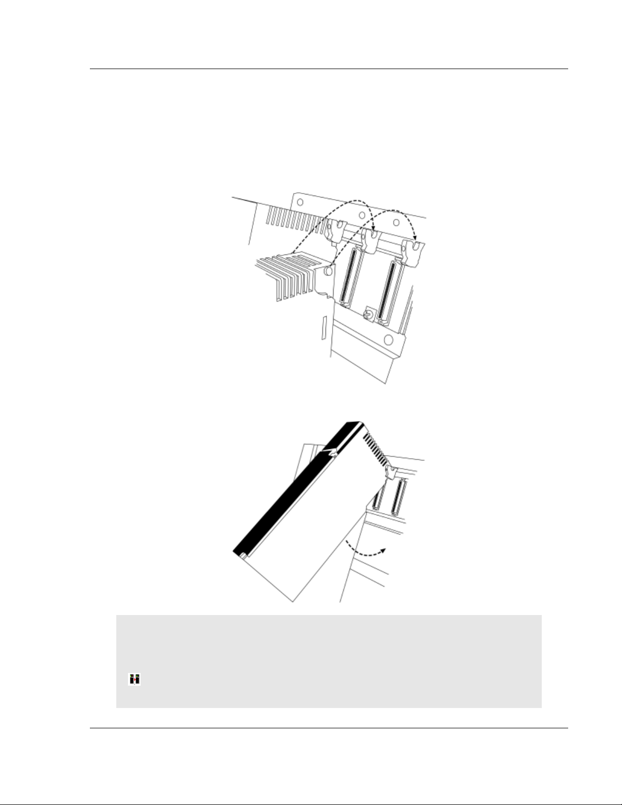
1.4 Installing the Module
1.4.1 Installing the ProTalk Module in the Quantum Rack
1 Place the module in the Quantum rack. The ProTalk module must be placed
in the same rack as the processor.
2 Tilt the module at a 45 angle and align the pegs at the top of the module with
the slots on the backplane.
3 Push the module into place until it seats firmly in the backplane.
CAUTION: The PTQ module is hot-swappable, meaning that you can install and remove it while
the rack is powered up. You should not assume that this is the case for all types of modules unless
the user manual for the product explicitly states that the module is hot-swappable. Failure to
observe this precaution could result in damage to the module and any equipment connected to it.
HSBY Note: For HSBY setup, repeat the above procedures for the Primary and Standby
modules.
ProSoft Technology, Inc. Page 17 of 306
August 12, 2014
Page 18

Start Here PTQ-PDPMV1 ♦ Quantum Platform
User Manual PROFIBUS DP Master Network Interface Module for Quantum
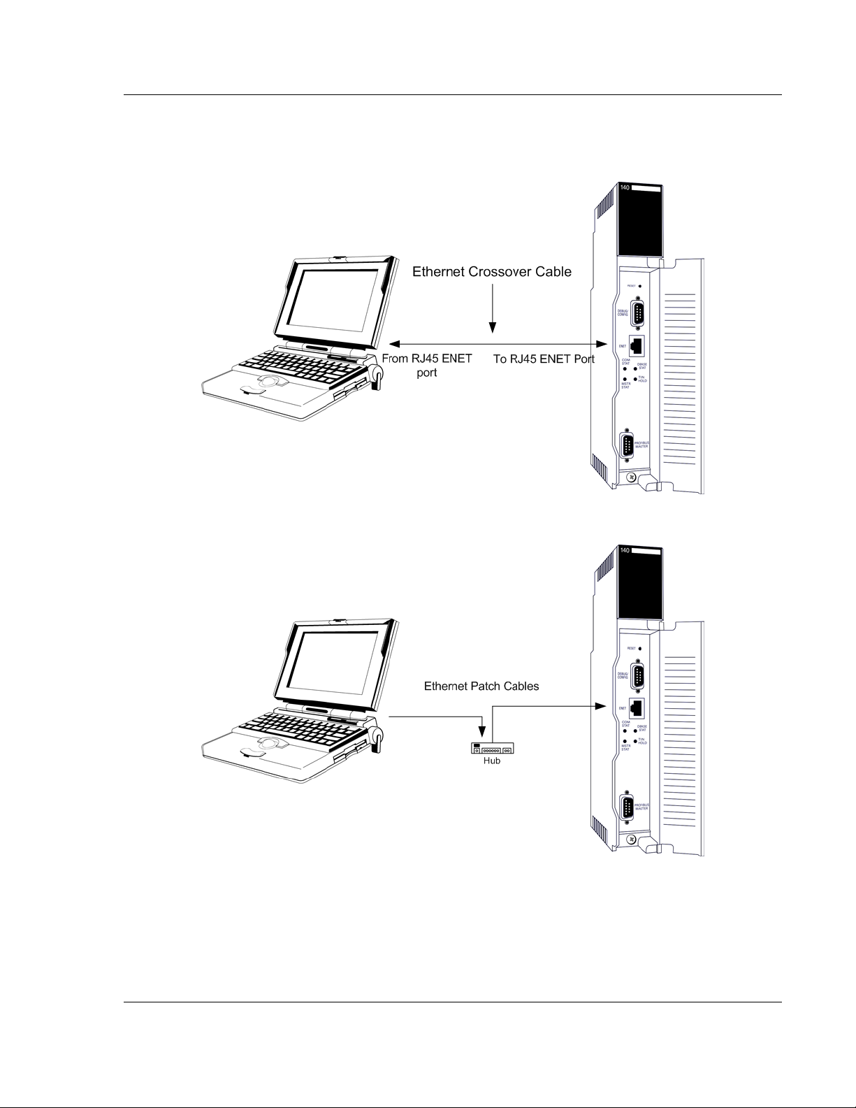
1.4.2 Connecting to the ProTalk Configuration/Debug Port
Note: The module has a serial port as well as an Ethernet port. The first time you connect to the
module to configure it, you can connect to the module’s serial port using the supplied null-modem
cable, because the module’s default Ethernet settings may not match your network.
HSBY Note: For HSBY units the Ethernet connection must be applied. This connection is used
as a backup to ping status messages over the PROFIBUS network. It is also used for DPV1
remote (passive) Master buffer update during switchover.
PC to Ethernet Port Connection
Important: The PTQ-PDPMV1 module is equipped to use an Ethernet connection using the
following defaults:
My_ip: 192.168.0.100
Netmask: 255.255.255.0
Gateway: 192.168.0.1
HSBY Note: For HSBY units the remote (passive) Master module Ethernet connection is
always Primary IP plus 1. For example, Primary IP = 192.168.0.100, Standby module IP =
192.168.0.101. This setting is not configurable: the module's firmware automatically sets the IP
address of the remote (passive) Master.
If you cannot use these defaults for your connection, you must change them
using ProSoft Configuration Builder and then download the new values to the
PTQ-PDPMV1 module, either through a serial cable, or by using a Compact
Flash (CF) writer. If you need to change the Ethernet addresses, use ProSoft
Configuration Builder to change the values in the WATTCP file.
Page 18 of 306 ProSoft Technology, Inc.
August 12, 2014
Page 19
PTQ-PDPMV1 ♦ Quantum Platform Start Here
PROFIBUS DP Master Network Interface Module for Quantum User Manual
If the default values are valid on your network, and you are using an Ethernet
connection, please connect your computer to the PTQ-PDPMV1 module using
either of the methods described below:
Computer to Ethernet Port Connection via Hub
1.4.3 PTQ-PDPMV1 Configuration / Debug Port Note
After the Ethernet settings are correctly configured, only the Ethernet port should
be used for configuration changes, diagnostics, and PROFIBUS monitoring.
ProSoft Technology, Inc. Page 19 of 306
August 12, 2014
Page 20

Start Here PTQ-PDPMV1 ♦ Quantum Platform
User Manual PROFIBUS DP Master Network Interface Module for Quantum
Page 20 of 306 ProSoft Technology, Inc.
August 12, 2014
Page 21

PTQ-PDPMV1 ♦ Quantum Platform Configuring the Module
In This Chapter
Configuring the Module with ProSoft Configuration Builder ................... 22
Downloading the Ethernet Configuration to the Module ........................ 33
Configuring the PROFIBUS Master ....................................................... 34
PROFIBUS DP Master Network Interface Module for Quantum User Manual
2 Configuring the Module
ProSoft Technology, Inc. Page 21 of 306
August 12, 2014
Page 22
Configuring the Module PTQ-PDPMV1 ♦ Quantum Platform
User Manual PROFIBUS DP Master Network Interface Module for Quantum
2.1 Configuring the Module with ProSoft Configuration Builder
In this step of the setup process, you will use ProSoft Configuration Builder to
configure the parameters that affect the interface between the PTQ module and
the processor (Quantum or Unity). These parameters indicate:
The physical position of the module in the rack.
HSBY Note: For HSBY units, the local (active) and passive modules must be placed in the
same rack location in both racks.
The starting memory address in the processor's State RAM for the module's
input and output data images. For the purpose of this example, we use a
starting address of 1000 for the input image and 3000 for the output image.
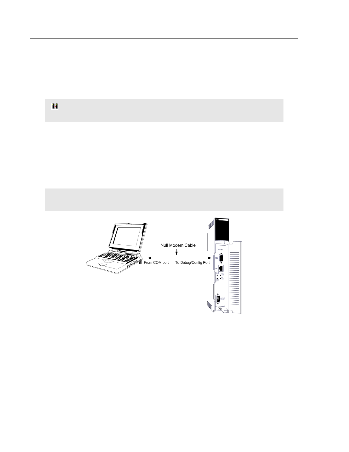
To begin, verify that the processor is correctly positioned in the rack, and is
powered up. Connect your PC to the PTQ-PDPMV1 module using the supplied
Null Modem serial cable, as shown in the following illustration.
Note: The serial port should only be used for initial configuration of the Ethernet port through
ProSoft Configuration Builder.
After the Ethernet settings are correctly configured, only the Ethernet port should
be used for configuration changes, diagnostics, and PROFIBUS monitoring.
Page 22 of 306 ProSoft Technology, Inc.
August 12, 2014
Page 23
PTQ-PDPMV1 ♦ Quantum Platform Configuring the Module
PROFIBUS DP Master Network Interface Module for Quantum User Manual
2.1.1 Setting Up the Project
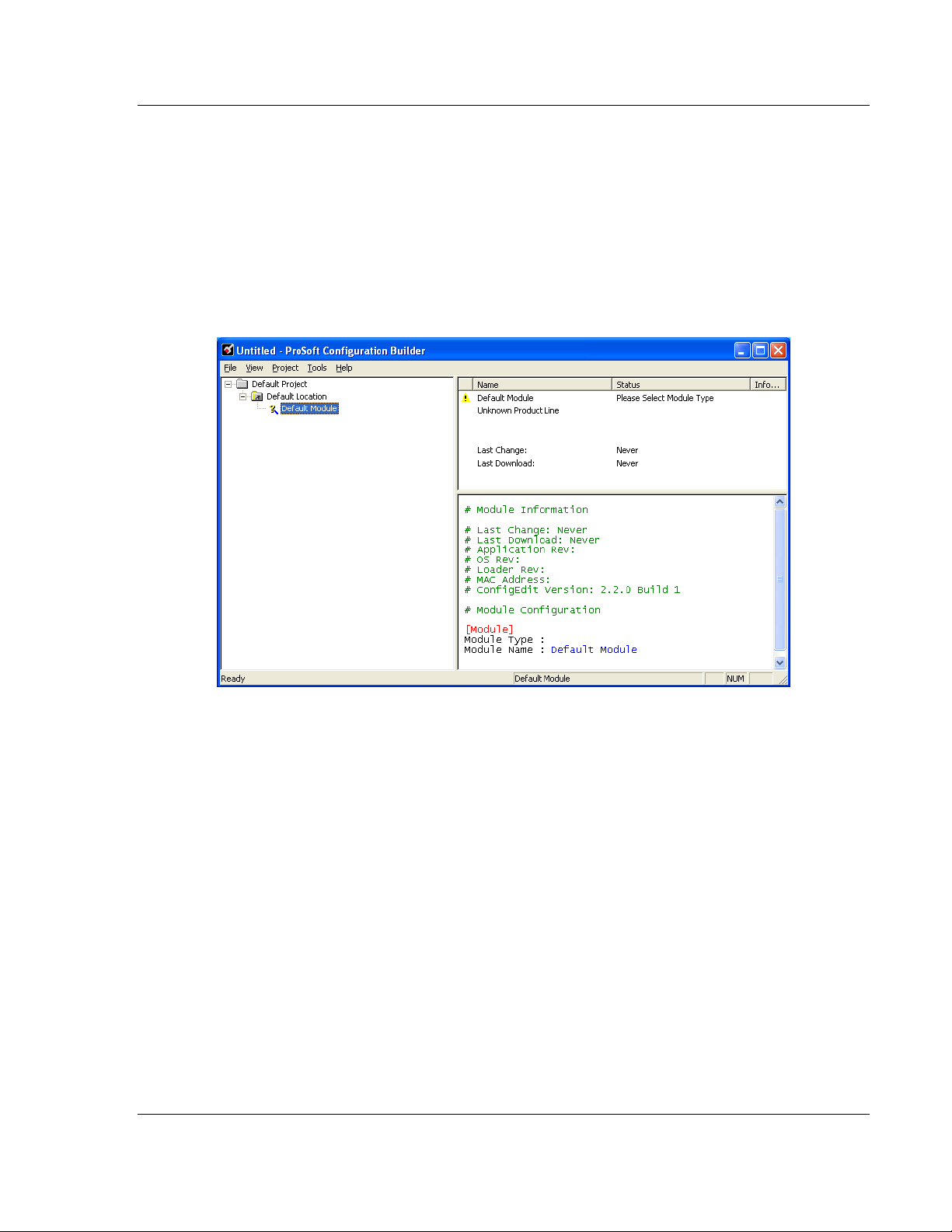
To begin, start ProSoft Configuration Builder. If you have used other Windows
configuration tools before, you will find the screen layout familiar. ProSoft
Configuration Builder’s window consists of a tree view on the left, and an
information pane and configuration pane on the right side of the window.
When you first start ProSoft Configuration Builder, the tree view consists of
folders for Default Project and Default Location, with a Default Module in the
Default Location folder. The illustration below shows the ProSoft Configuration
Builder window with a new project.
Your first task is to add the PTQ-PDPMV1 module to the project.
1 Use the mouse to select DEFAULT MODULE in the tree view, and then click the
right mouse button to open a shortcut menu.
ProSoft Technology, Inc. Page 23 of 306
August 12, 2014
Page 24
Configuring the Module PTQ-PDPMV1 ♦ Quantum Platform
User Manual PROFIBUS DP Master Network Interface Module for Quantum
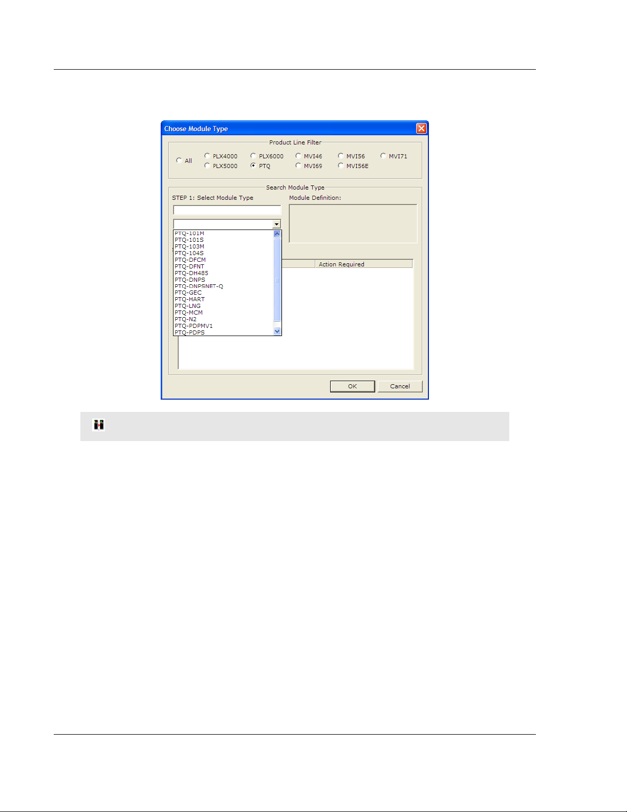
2 On the shortcut menu, select CHOOSE MODULE TYPE. This action opens the
Choose Module Type dialog box.
HSBY Note: For Hot Standby support, select the Enable "Hot Standby" checkbox.
3 In the Product Line Filter area of the dialog box, select PTQ. In the Select
Module Type dropdown list, select PTQ-PDPMV1, and then click OK to save
your settings and return to the ProSoft Configuration Builder window.
The next task is to set the module parameters.
Page 24 of 306 ProSoft Technology, Inc.
August 12, 2014
Page 25
PTQ-PDPMV1 ♦ Quantum Platform Configuring the Module
PROFIBUS DP Master Network Interface Module for Quantum User Manual
2.1.2 Setting Module Parameters
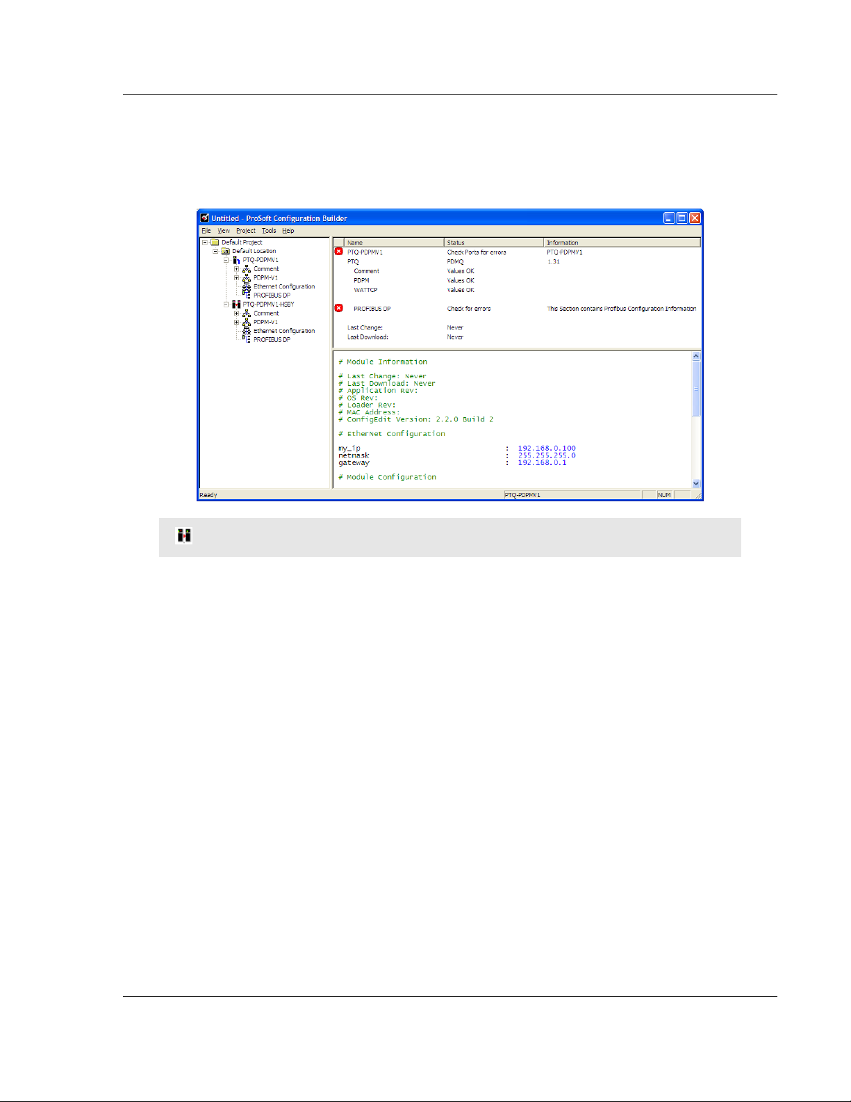
Notice that the contents of the information pane and the configuration pane
changed when you added the PTQ-PDPMV1 module to the project. The red "X"
icon indicates that the module’s configuration is incomplete.
HSBY Note: For Hot Standby modules, a double module icon will be displayed.
In the following steps, you will provide the missing information to begin
configuring the module.
1 Click the plus sign [+] next to the module to expand the module tree, and
then expand the PDPM-V1 tree.
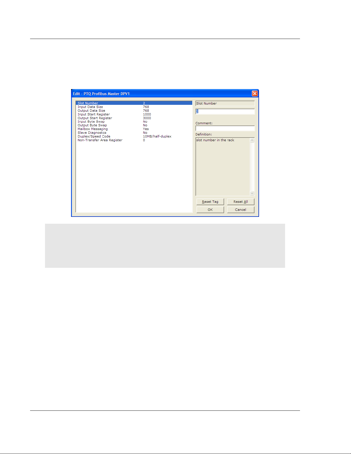
2 Double-click the PTQ PROFIBUS MASTER DPV1 object. This action opens
the Edit dialog box.
ProSoft Technology, Inc. Page 25 of 306
August 12, 2014
Page 26
Configuring the Module PTQ-PDPMV1 ♦ Quantum Platform
User Manual PROFIBUS DP Master Network Interface Module for Quantum
3 In the Edit dialog box, change the values for the selections in this section of
the configuration to match the values in the following illustration. To change a
value, select the parameter to modify in the left pane, and then type the new
value in the edit field in the right pane. If you are not sure what to enter here,
use the default values.
Note: The values you enter for the purpose of this example configuration are used by the sample
program that you will download to the processor later in this section. You may need to change
these values as you implement your production system. Use the following chapters for your
Quantum or Unity configuration software, or the online help system, for detailed information on
each of the parameters associated with the module.
Page 26 of 306 ProSoft Technology, Inc.
August 12, 2014
Page 27
PTQ-PDPMV1 ♦ Quantum Platform Configuring the Module
PROFIBUS DP Master Network Interface Module for Quantum User Manual
Slot Number
The Slot Number is the physical location of the module in the rack. The example
here assumes a basic configuration with a power supply occupying the first slot,
the processor occupying the next two slots, and the PTQ-PDPMV1 module
occupying the fourth slot. In this case the module would be in slot 4.
Note: If the module is not placed in the slot number specified, the module will not operate, and the
CFG ERR light will illuminate. You must specify the actual slot number for the module in the
module configuration file.
Input Data Size
Number of PROFIBUS input point words. Leave this setting at its default value of
768 words.
Output Data Size
Number of PROFIBUS output point words. Leave this setting at its default value
of 768 words.
Start Registers
ProSoft Technology, Inc. Page 27 of 306
August 12, 2014
Page 28

Configuring the Module PTQ-PDPMV1 ♦ Quantum Platform
User Manual PROFIBUS DP Master Network Interface Module for Quantum
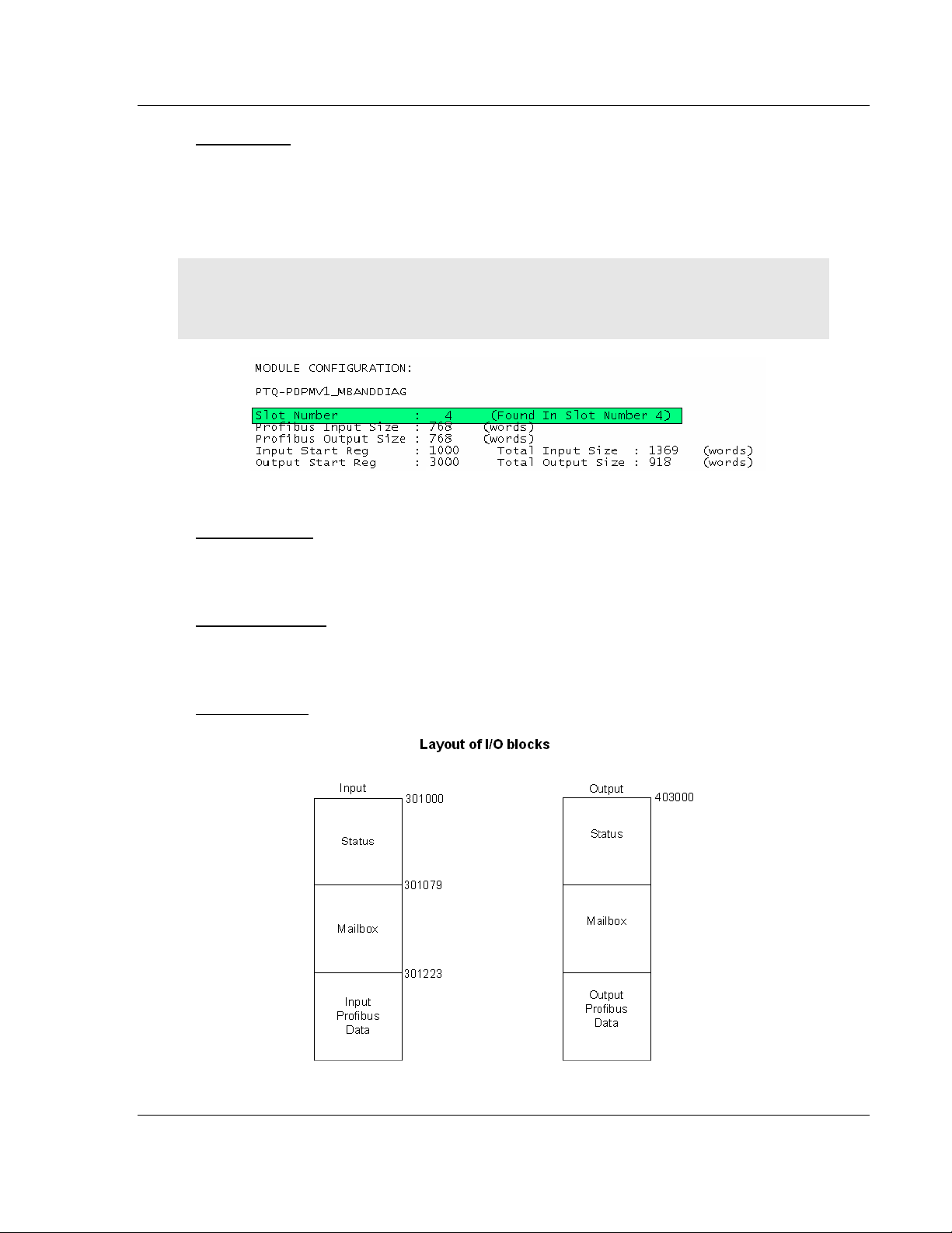
The Input Start Register address refers to the 3x (%IW) location in the
processor’s State RAM and the Output Start Register refers to the 4x (%MW)
location of State RAM. You can view State RAM information in Unity XL Pro.
A common mistake is to assume that because the Input Start Register parameter
starts at address 301000, then the PROFIBUS data associated with the slaves
will also start at the same register. As the diagram above shows, the Input
PROFIBUS Data would start at address 301223 for this example.
Important: The Input and Output Start Register parameters define the start registers for the input
and output blocks that are transferred between the processor and the module. The PROFIBUS I/O
associated to the slaves is part of these blocks. Refer to PTQ Input and Output Data Blocks (page
251) for a description. Each block contains status, PROFIBUS data, and Mailbox/Slave
diagnostics, if chosen.
Input Start Register
The Input Start Register address refers to the 3x (%IW) location in the
processor’s State RAM. You can view State RAM information in Unity XL Pro.
Output Start Register
The Output Start Register refers to the 4x (%MW) location of State RAM. You
can view State RAM information in Unity XL Pro.
Input Byte Swap
Swap bytes in input image (YES or NO). The default value is NO.
This is a user-configured flag to indicate if input data is swapped before being
placed in the input image for the controller. If the parameter is set to 0, no
swapping occurs. If it is not 0, then bytes are swapped.
For more information on byte swapping, please refer to Status Data in the Input
Data Block (page 256).
Output Byte Swap
Swap bytes in output image (YES or NO). The default value is NO.
This is a user-configured flag to indicate if output data is swapped after being
received from the controller. If the parameter is set to 0, no swapping occurs. If it
is not 0, then bytes are swapped.
Mailbox Messaging
Use mailbox messaging over the backplane (Y or N with Y=default).
For this example, leave the setting at its default. For more information on the
effect of this setting, please refer to Mailbox Messaging (page 151).
Page 28 of 306 ProSoft Technology, Inc.
August 12, 2014
Page 29
PTQ-PDPMV1 ♦ Quantum Platform Configuring the Module
PROFIBUS DP Master Network Interface Module for Quantum User Manual
Slave Diagnostics
Get slave diagnostic data (Y/N with N=default).
For this example, leave the setting at its default.
If you change the default value of this setting and the previous one (Mailbox
Messaging) from their default values, the layout of the I/O blocks changes.
The following diagram shows the layout of the I/O blocks when Mailbox
Messaging is set to YES (the default value), and Get Slave Diagnostic Data is set
to YES.
ProSoft Technology, Inc. Page 29 of 306
August 12, 2014
Page 30
Configuring the Module PTQ-PDPMV1 ♦ Quantum Platform
User Manual PROFIBUS DP Master Network Interface Module for Quantum
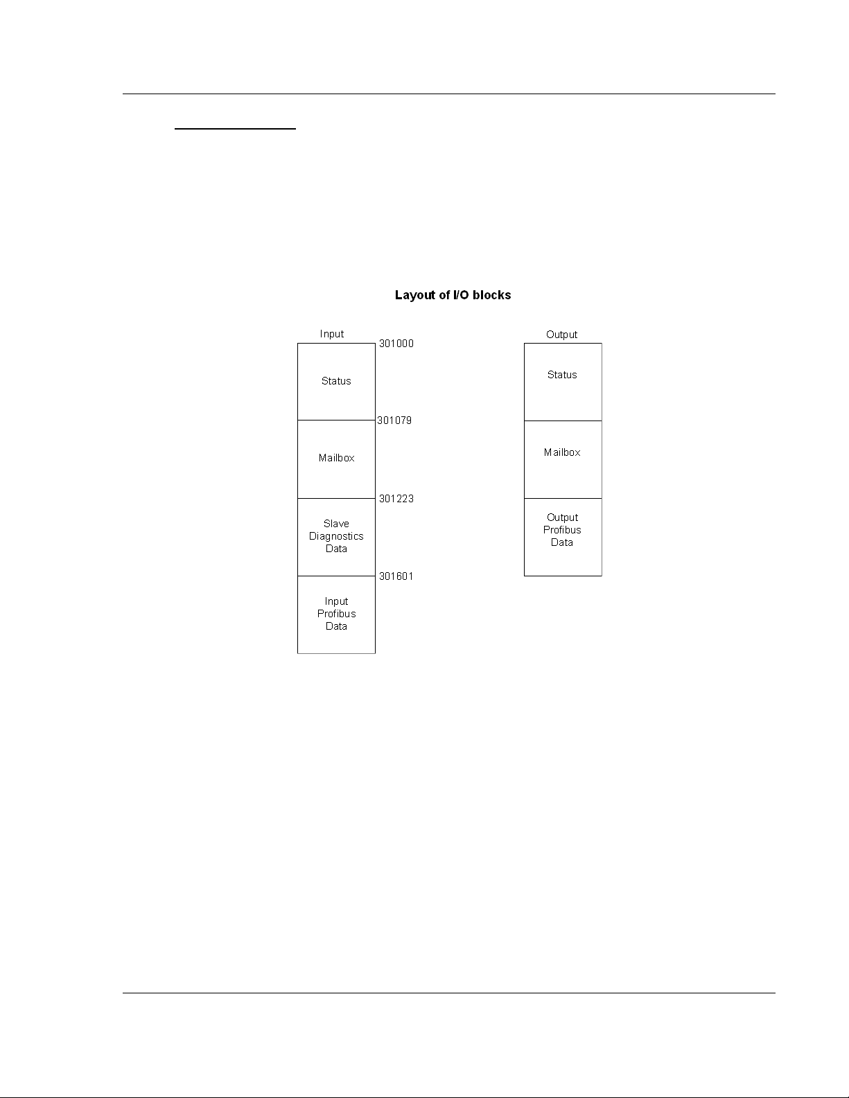
The following diagram shows the layout of the I/O blocks if Mailbox Messaging is
set to NO, and Slave Diagnostics to YES.
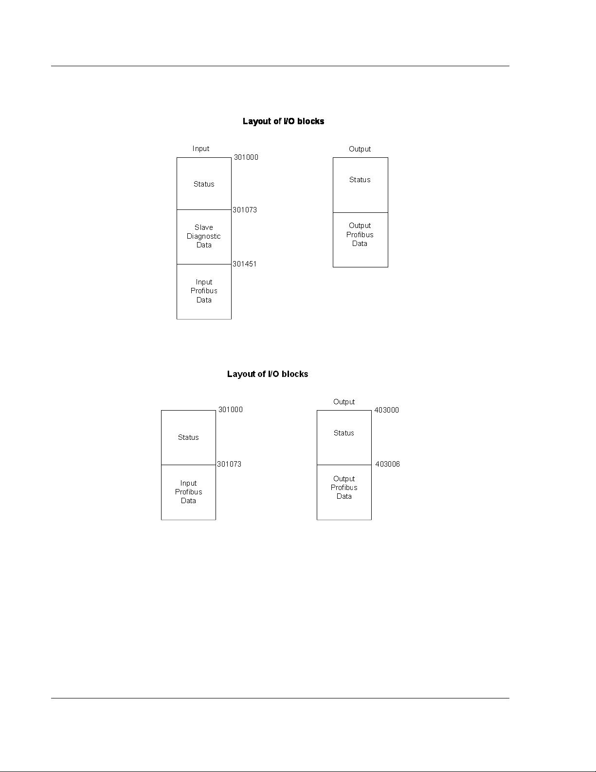
The following diagram shows the layout of the I/O blocks if Mailbox Messaging is
set to NO, and Slave Diagnostics to NO.
In ProSoft Configuration Builder, the Show Concept Map and Show Unity Map
commands show the layout of the entire input and output backplane blocks.
Refer to Input and Output Data Block Format (page 251) for detailed information
on the contents of these blocks, and a discussion of how various configuration
options change the layout of these blocks.
Page 30 of 306 ProSoft Technology, Inc.
August 12, 2014
Page 31

PTQ-PDPMV1 ♦ Quantum Platform Configuring the Module
PROFIBUS DP Master Network Interface Module for Quantum User Manual
Duplex/Speed Code
0=Auto-negotiate
1=10 MB / half-duplex
2=10 MB / full-duplex
3=100 MB / half-duplex
4=100 MB / full-duplex
This parameter allows you to set the connection speed manually between 10
Mbps full / half-duplex and 100 Mbps full / half-duplex or to auto-negotiate the
baud rate with a hub or switch. The default value is 10 MB / half-duplex.
Non-Transfer Area Register
Note: This configuration option is only available for Hot Standby operation.
If this parameter is set to 0, the PROFIBUS configuration CRC will be derived
from the Output Area.
If this parameter is set to a value GREATER THAN 0, the PROFIBUS configuration
CRC will be derived from the specified Non-Transfer Area register.
You can specify a register outside the Output Area to derive the CRC value for
the PROFIBUS configuration. This parameter allows you to modify the
PROFIBUS DP network configuration without stopping the system.
This data area uses 4 words, and must be located in the 4x memory area. The
module will attempt to read this data asynchronously from the non-transfer data
area. When new values are received, they are placed in the normal area used by
the program. Because this operation is asynchronous to the scan, it may take 2
or more scans for the data to update.
Completing the Example Configuration
When you have finished updating the values, click OK to save your settings and
return to the ProSoft Configuration Builder window.
At this time, you may wish to rename the Default Project and Default Location
folders in the tree view. To rename an object:
1 Select the object, and then click the right mouse button to open a shortcut
menu. From the shortcut menu, choose RENAME.
2 Type the name to assign to the object.
3 Click away from the object to save the new name.
The next task is to update the module's Ethernet settings. This allows you to
connect from your computer to the module using an Ethernet cable rather than a
serial cable.
ProSoft Technology, Inc. Page 31 of 306
August 12, 2014
Page 32

Configuring the Module PTQ-PDPMV1 ♦ Quantum Platform
User Manual PROFIBUS DP Master Network Interface Module for Quantum
2.1.3 Updating the Ethernet Settings
Use this procedure to configure the Ethernet settings for your module. You must
assign an IP address, subnet mask and gateway address. After you complete
this step, you can connect to the module with an Ethernet cable.
1 Determine the network settings for your module, with the help of your network
administrator if necessary. You will need the following information:
o IP address (fixed IP required) _____ . _____ . _____ . _____
o Subnet mask _____ . _____ . _____ . _____
o Gateway address _____ . _____ . _____ . _____
HSBY Note: Hot Standby Primary IP is entered. The Standby IP address will always be the
Primary IP address plus 1.
2 Click [+] to expand the tree for the PTQ-PDPMV1 module.
3 Double-click the ETHERNET CONFIGURATION object. This action opens the Edit
dialog box.
4 Edit the values for my_ip, netmask (subnet mask) and gateway (default
gateway).
5 When you are finished editing, click OK to save your changes and return to
the ProSoft Configuration Builder window.
Page 32 of 306 ProSoft Technology, Inc.
August 12, 2014
Page 33

PTQ-PDPMV1 ♦ Quantum Platform Configuring the Module
PROFIBUS DP Master Network Interface Module for Quantum User Manual
2.2 Downloading the Ethernet Configuration to the Module
In order for your changes to take effect, you must download (copy) the updated
Ethernet configuration from your computer to the module.
1 Connect the serial cable between the module and the computer.
2 Select the ETHERNET CONFIGURATION icon, and then click the right mouse
button to open a shortcut menu. On the shortcut menu, choose DOWNLOAD.
This action sends the new IP settings to the module, allowing Ethernet
communication between the computer and the module.
HSBY Note: This serial download procedure must be performed for both Master HSBY
modules.
Note: The processor (Quantum or Unity) must be in STOP mode before you download the file to
the module. Use the processor’s softkeys on the display keypad, or the processor’s configuration
program to stop the processor.
The final step is to verify that ProSoft Configuration Builder can communicate
with the module using an Ethernet connection.
1 Plug in an Ethernet cable between the module and an Ethernet hub or router.
HSBY Note: You must leave the Ethernet cable connected to both Hot Standby modules at all
times. The configuration download will not proceed unless both modules are connected.
2 In the tree view in ProSoft Configuration Builder, click once to select the PTQ-
PDPMV1 module.
3 Open the PROJECT MENU, and then choose MODULE, and then choose
DIAGNOSTICS. This action opens the Diagnostics window.
4 Choose Ethernet as the connection type, and then enter the IP address.
Press the [?] key on your keyboard. If the module is communicating
successfully, you will see a menu like this:
ProSoft Technology, Inc. Page 33 of 306
August 12, 2014
Page 34

Configuring the Module PTQ-PDPMV1 ♦ Quantum Platform
User Manual PROFIBUS DP Master Network Interface Module for Quantum
2.3 Configuring the PROFIBUS Master
In this task, you will configure the PROFIBUS Master, and then add PROFIBUS
slaves to the network. When this step is complete, you will download the
configuration information to the PTQ module. You will also export the I/O maps
for the processor.
1 In ProSoft Configuration Builder tree view, click [+] to expand the PTQ-
PDPMV1 tree, and then double-click the PROFIBUS DP icon. This action
opens the PROFIBUS Master Setup dialog box.
2 Click the CONFIGURE PROFIBUS button. This action opens the ProSoft
Configuration Builder for PROFIBUS application.
3 Click [+] to expand the PROFIBUS Master tree.
4 Drag the ProTalk icon into the Bus Configuration window. This is
automatically done by the software for new applications.
For HSBY Units
Page 34 of 306 ProSoft Technology, Inc.
August 12, 2014
Page 35

PTQ-PDPMV1 ♦ Quantum Platform Configuring the Module
PROFIBUS DP Master Network Interface Module for Quantum User Manual
5 Double-click the PROFIBUS MASTER icon in the Bus Configuration window.
This action opens the Master Properties dialog box.
6 On the COMMON tab, name your PROFIBUS drop. The name should match
the module name from step 4 in this procedure.
Note: The PROFIBUS tab contains the address setting and advanced configuration settings for the
Master. The default settings on this tab work best in most applications.
HSBY Note: The correct profile setting for HSBY Master is DP; however, the Hot Standby
check box will be checked. The minimum baud for Hot Standby module to switch over within 300
ms with an average processor scan time of 100ms, is 1500Kbits/second.
7 Click OK to save your changes and return to the Bus Configuration window.
2.3.1 Installing the GSD Files
The GSD configuration files contain information on PROFIBUS slaves that you
can configure as part of your PROFIBUS network. In order for this configuration
information to be available in ProSoft Configuration Builder, you must install the
GSD files.
Tip: GSD configuration files for popular Schneider Electric and ProSoft Technology modules are
included with the installation. If you have other GSD files for your PROFIBUS slaves, copy them
into C:\Documents and Settings\All Users\Application Data\ProSoft\GSD (Windows XP / 2000) or
C:\My Documents\ (Windows 98), and ProSoft Configuration Builder will load them automatically.
ProSoft Technology, Inc. Page 35 of 306
August 12, 2014
Page 36

Configuring the Module PTQ-PDPMV1 ♦ Quantum Platform
User Manual PROFIBUS DP Master Network Interface Module for Quantum
To install GSD files manually
1 In ProSoft Configuration Builder tree view, click [+] to expand the PTQ-
PDPMV1 tree, and then double-click the PROFIBUS DP icon. This action
opens the PROFIBUS Master Setup dialog box.
2 Click the CONFIGURE PROFIBUS button. This action opens the ProSoft
Configuration Builder for PROFIBUS application.
3 Click [+] to expand the PROFIBUS DP tree.
4 Click the right mouse button to open a shortcut menu.
5 On the shortcut menu, choose INSTALL NEW GS* FILE. This action opens a
dialog box that allows you to browse for the location of the GSD configuration
files to install.
6 Choose the file to install, and then click OPEN. If the file already exists in the
configuration file path (see Tip above), you will be prompted to overwrite the
file.
7 You will be prompted to associate the GSD configuration file with a bitmap
image of the slave device. Use the File Open dialog box to browse for the
location of the image file to use.
Note: This procedure does not automatically copy GSD configuration files from their original
location to the GSD file path. In order to load GSD files automatically the next time you start
ProSoft Configuration Builder, copy the files to the configuration file path in the Tip above.
2.3.2 Configuring the PROFIBUS Slaves
There are two essential steps to configuring a slave:
1 Add the slave in ProSoft Configuration Builder (PCB) as a device connected
to the PROFIBUS Master, specifying the slave address and any necessary
input and output configuration. Download the PROFIBUS Master
configuration to the PTQ-PDPMV1 module.
2 Configure the slave (using PCB or the configuration tool supplied by the
manufacturer, for some PROFIBUS slaves). Verify that the slave address
configured in the slave module matches the slave address configured in PCB.
Download the PROFIBUS Slave configuration to the slave module.
Page 36 of 306 ProSoft Technology, Inc.
August 12, 2014
Page 37

PTQ-PDPMV1 ♦ Quantum Platform Configuring the Module
PROFIBUS DP Master Network Interface Module for Quantum User Manual
Scanning for Slaves Manually
In this part of the procedure, you will add and configure the PROFIBUS slaves. In
the following steps, you will add and configure a ProLinx PROFIBUS slave
module. The configuration information (.GSD file) for this module is provided on
the PTQ-PDPMV1 Solutions CD-ROM.
1 In ProSoft Configuration Builder for PROFIBUS, click the plus sign [+] to
expand the PROFIBUS DP tree.
2 Navigate to the folder containing the type of slave device to add, and then
click the plus sign [+] to expand the folder.
3 Drag the SLAVE icon into the Bus Configuration window. The slave device
appears in the Bus Configuration window as a network location to the Master.
4 In the tree view, click the plus sign [+] to expand the slave device you added.
This action opens a list of device configuration values. The following
illustration shows the device configuration values for a ProLinx PROFIBUS
slave. The values for other devices may be different, so you should review
the specifications for the product you are installing in order to determine the
correct values to use.
ProSoft Technology, Inc. Page 37 of 306
August 12, 2014
Page 38

Configuring the Module PTQ-PDPMV1 ♦ Quantum Platform
Input Address configured in PCB (Bytes)
Actual Quantum Input Register Address (Words)
0...1
301223
2...3
301224
4...5
301225
...
...
User Manual PROFIBUS DP Master Network Interface Module for Quantum
5 Drag the input and output parameters to the slot location grid below the Bus
Configuration window. This view displays the configuration data, order
number, and starting input and output addresses.
Important: The starting input and output addresses that you select here are actually byte offsets
within the PROFIBUS Data area inside each Input and Output backplane block.
For example, for the sample configuration for the input block, where the Input Start Register
Parameter = 1000:
The following table shows the actual Quantum address:
Page 38 of 306 ProSoft Technology, Inc.
August 12, 2014
Page 39

PTQ-PDPMV1 ♦ Quantum Platform Configuring the Module
PROFIBUS DP Master Network Interface Module for Quantum User Manual
6 Double click the SLAVE icon to view the Slave properties.
In particular, note the following settings:
o Automatic PROFIBUS Address Assignment:
ProSoft Configuration Builder automatically assigns a PROFIBUS address
to each new slave. The address assignment begins at address 3, and is
incremented by 1 for each new slave added to the network. You can
change the address in the COMMON tab of the Slave Properties dialog
box.
o Automatic Input/Output Address Assignment:
For each new slave added to the PROFIBUS network, ProSoft
Configuration Builder automatically converts the input/output byte
addresses to word input/output addresses for the State RAM in the
processor.
7 Repeat steps 2 through 6 for all slaves you intend to place on the network.
8 When you are finished adding slaves, open the PROJECT menu and choose
EXIT to return to the Master Setup dialog box.
ProSoft Technology, Inc. Page 39 of 306
August 12, 2014
Page 40

Configuring the Module PTQ-PDPMV1 ♦ Quantum Platform
User Manual PROFIBUS DP Master Network Interface Module for Quantum
Using The Autoscan Feature
The concept of Automatic network scanning means that the user can instruct the
Bus Configuration window to automatically gather information about slaves that
are connected to the network. When the scan is completed the user can adopt
the detected slaves to the bus configuration and download to the Master.
This is a quick way to get a network up and running. However, one should be
aware that it is not guaranteed that any particular slave will enter data exchange
since the user parameter data might not match. This is especially obvious if no
associated GSD-file is found during the network scan, this means that no user
parameter data would be sent to the slave.
NETWORK SCAN is selectable from the Online menu as well as from the drop-
down menu for the MASTER icon.
Page 40 of 306 ProSoft Technology, Inc.
August 12, 2014
Page 41

PTQ-PDPMV1 ♦ Quantum Platform Configuring the Module
PROFIBUS DP Master Network Interface Module for Quantum User Manual
When the download is completed, the PROFIBUS Master Configuration window
will initialize the Master to operate as a Class 2 Master only. In this mode it is
possible to initialize the Master even if the database does not contain any slaves.
After successful initialization, the PROFIBUS Master Configuration window will
issue the following mailboxes in order to gather information about the connected
slaves:
1 1. Send FB_APPL_GET_LIVE_LIST in order to detect connected slaves,
2 2. Send FB_APPL_GET_SLAVE_DIAG (external request) to all devices
identified as slaves according to the Live list.
3 3. Send FB_APPL_GET_SLAVE_CONFIG to all devices identified as slaves
according to the Live list.
When the information is collected the PROFIBUS Master Configuration window
will find a matching GSD-file and extract information from it. Refer to the
flowchart below for this sequence:
GSD Selection Algorithm
If two or more matching GSD-files are found, the first one found should be
selected. The other compatible files should be stored so that the user can select
one of them instead. If the user selects another GSD-file, the PROFIBUS Master
Configuration window will run through the Module Selection Algorithm (described
below) again.
ProSoft Technology, Inc. Page 41 of 306
August 12, 2014
Page 42

Configuring the Module PTQ-PDPMV1 ♦ Quantum Platform
User Manual PROFIBUS DP Master Network Interface Module for Quantum
Module Selection Algorithm
The algorithm used to find modules in the GSD based on the Identifier byte(s) is
as follows:
Select the module that matches the largest number of Identifier bytes. If the GSD
contains two or more modules with the exact set of Identifier bytes, use the first
module found.
Example:
If a slave responds with identifier bytes: 0x11, 0x21, 0x31 and that the associated
GSD-file contains five modules: “A” = 0x11, “B” = 0x21, “C” = 0x31, “AB” = 0x11,
0x21 and “BC” = 0x21, 0x31. The PROFIBUS Master Configuration window will
then select modules "AB" and "C".
Note: If no matching module is found in the GSD, The PROFIBUS Master Configuration window
will display the identifier byte(s) instead.
Network scan window
The information extracted from the GSD-file(s) will be displayed in the Network
scan window.
Select
In this column all found slaves will be marked as selected by default, except for
slaves with the special address 126 (refer to the next section that describes the
Address column). Only selected slaves will be added to the PROFIBUS Master
Configuration when the ADOPT SELECTED SLAVES button is clicked.
Address
In this column the node address of the slaves will be displayed. Found slaves
should be listed in ascending order according to their node addresses.
Page 42 of 306 ProSoft Technology, Inc.
August 12, 2014
Page 43

PTQ-PDPMV1 ♦ Quantum Platform Configuring the Module
PROFIBUS DP Master Network Interface Module for Quantum User Manual
Special address 126 -Set Slave address:
If a slave with node address 126 is detected during the network scan, the
PROFIBUS Master Configuration window will display the address in red color. It
will not be possible for the user to adopt the slave to the configuration since it is
not allowed to exchange data with devices having this address. The check box in
the Select column will be grayed out.
To be able to adopt a slave with address 126 the user must first assign a valid
address by clicking the icon next to the node address. By doing so the Set Slave
Address dialog box is started.
Note that the Old slave address is preset to a value of 126 that is not editable (grayed out).
ProSoft Technology, Inc. Page 43 of 306
August 12, 2014
Page 44

Configuring the Module PTQ-PDPMV1 ♦ Quantum Platform
User Manual PROFIBUS DP Master Network Interface Module for Quantum
If the Slave is in the configuration already then it will not affect the addressing.
Example:
After scanning, the network finds these other slaves: 2, 6, 25, and 40
Slaves 2, 6, and 25 are found, but are marked as in the bus configuration (the
mapping of the inputs and outputs will not be affected)
Slaves 40 is new and could be added and the input/output addressing will be
appended to the end as shown on the last screen.
Page 44 of 306 ProSoft Technology, Inc.
August 12, 2014
Page 45

PTQ-PDPMV1 ♦ Quantum Platform Configuring the Module
PROFIBUS DP Master Network Interface Module for Quantum User Manual
The PROFIBUS Master Configuration window will prevent the user from selecting
a New slave address that is already occupied by another device; this includes
detected Master stations as well. If the user selects an occupied address, a
message similar to the one shown here will open.
When an address has been successfully assigned, the PROFIBUS Master
Configuration window will update the Network scan window as shown here. The
node address will be updated to the one that the user selected in the Set Slave
dialog box. The check box in the Select column will be marked allowing the user
to adopt the slave to the configuration.
Slave
In this column the name of the slave as stated in the assigned GSD-file will be
displayed. If no matching GSD-file is found the Ident number will be displayed in
red color in the drop-down list.
Module
This column shows the name of the module(s) as stated in the assigned GSDfile, which matches the Identifier byte(s) derived from the GetCfg mailbox
message. If no GSD-file or no matching module is found the Identifier byte(s) will
be displayed in red color. If the configuration for a slave is constructed of several
modules, the modules will be listed under each other.
ProSoft Technology, Inc. Page 45 of 306
August 12, 2014
Page 46

Configuring the Module PTQ-PDPMV1 ♦ Quantum Platform
User Manual PROFIBUS DP Master Network Interface Module for Quantum
If there is more than one module in the GSD-file that matches the Identifer bytes,
the first matching module will be displayed in blue color in a drop-down list. The
drop-down list will contain all other matching modules so that the user can select
the desired one.
Note: Only modules that have the exact same Identifer bytes as the first matching module will be
displayed in the drop-down list.
GSD-file
This column shows the name of the GSD-file that matches the Ident number
derived from the SlaveDiag mailbox message. If there are more files with the
same Ident number in the device catalog, the first matching GSD-file will be
displayed in blue color in a drop-down list.
This could be the case if the device catalog contains two or more brand labeled
devices, or GSD-files for two or more languages (for example NICEDEV.GSD
and NICEDEV.GSE) exist.
Note: If the user selects another GSD-file, The PROFIBUS Master Configuration window will
update the modules for that slave accordingly.
Page 46 of 306 ProSoft Technology, Inc.
August 12, 2014
Page 47

PTQ-PDPMV1 ♦ Quantum Platform Configuring the Module
PROFIBUS DP Master Network Interface Module for Quantum User Manual
If no GSD-file is found the user will be able to copy the expected GSD to the
device catalog by clicking the icon next to the text No GSD found. This will start
the Install new GS*-file dialog box. When the file is installed, the PROFIBUS
Master Configuration window will verify that the installed file matches the slave
and update the modules for the slave accordingly.
Rescan
Pressing the YES button will trigger a new network scan. Before proceeding with
the scan a message similar to the one below will appear. If a new scan is
accepted, detected slaves found during the previous scan will be lost.
Adopt selected slaves
Pressing this button will cause all selected slaves to be adopted to the
PROFIBUS Master Configuration window. Before carrying on with this action a
message similar to the one below will appear.
ProSoft Technology, Inc. Page 47 of 306
August 12, 2014
Page 48

Configuring the Module PTQ-PDPMV1 ♦ Quantum Platform
User Manual PROFIBUS DP Master Network Interface Module for Quantum
If accepted, the network scan window will close and the PROFIBUS Master
Configuration window will be populated with the slaves that were found during
the network scan.
Note: Slave: is equal to the Ident number and that the Device path: and Order number/designation
fields are left empty.
Cancel and Help
If the CANCEL button is pressed a message similar to the one below will appear.
If the HELP button is pressed the online help will start.
Page 48 of 306 ProSoft Technology, Inc.
August 12, 2014
Page 49

PTQ-PDPMV1 ♦ Quantum Platform Configuring the Module
PROFIBUS DP Master Network Interface Module for Quantum User Manual
Set_Param (SAP61)
ProSoft PROFIBUS slave (PDPS) devices have a configurable parameter for
SPC3 User Prm Byte. The following illustration shows the value of this parameter
in ProSoft Configuration Builder for PROFIBUS, the configuration tool for ProSoft
PROFIBUS Master devices.
ProSoft Technology, Inc. Page 49 of 306
August 12, 2014
Page 50

Configuring the Module PTQ-PDPMV1 ♦ Quantum Platform
Byte
Bit Position
Designation
7 6 5 4 3 2 1 0
0
Lock
Reg
Unio
Req
Sync
Req
Free
Req
WD on
Res
Res
Res
Station status
1
WD_Fact_1
2
WD_Fact_2
3
MinTSDR
4
Ident_Number_High
5
Ident_Number_Low
6
Group_Ident
7
Spec_User_Prm_Byte
8 to 243
User_Prm_Data
Byte 7
Spec_User_Prm_Byte
Bit
Name
Significance
Default State
0
Dis_Startbit
The start bit monitoring in the receiver
is switched off with this bit
Dis_Startbit = 1,
Start bit monitoring is switched off.
1
Dis_Stopbit
Stop bit monitoring in the receiver is
switched off with this bit
Dis_Stopbit = 0
Stop bit monitoring is not switched off.
2
WD_Base
This bit specifies the time base used to
clock the watchdog.
WD_Base = 0: time base 10 ms
WD_Base = 1: time base 1 ms
WD_Base = 0
The time base is 10 ms.
3 to 4
Res
To be parameterized with 0
0
5
Publisher_Enable
DXB-publisher-functionality of the
SPC3 is activated with this bit
Publisher_Enable = 0, DXB-requesttelegrams are ignored;
Publisher_Enable = 1, DXB-requesttelegrams are processed
6 to 7
Res
To be parameterized with 0
0
User Manual PROFIBUS DP Master Network Interface Module for Quantum
Parameter Data Structure
SPC3 evaluates the first seven data bytes (without user prm data), or the first
eight data bytes (with user prm data). The first seven bytes are specified
according to the standard. The eighth byte is used for SPC3-specific
communications. The additional bytes are available to the application.
2.3.3 Exporting the Processor Memory Map
The import file (PTQ_PDPMV1.XSY for Unity, or PTQ_PDPMV1.DTY for
Concept) that you create in this step uses the information in the Processor
Memory Map to build the derived data tags for the slave devices on your
PROFIBUS network. These tags allow the program running on the processor to
access data within the module.
Page 50 of 306 ProSoft Technology, Inc.
August 12, 2014
Page 51

PTQ-PDPMV1 ♦ Quantum Platform Configuring the Module
PROFIBUS DP Master Network Interface Module for Quantum User Manual
To export the processor memory map
1 In the Master Setup dialog box, click SHOW CONCEPT MAP (for processors
configured with Concept software) or click SHOW UNITY MAP (for processors
configured with ProSoft Configuration Builder software).
2 This action opens the Memory Map dialog box.
3 On the Memory Map dialog box, click EXPORT PROCESSOR FILES.
Note: For Unity Map, PCB will export the XSY file and XFM files in the same directory if mailbox
parameter is chosen. The filenames will match the module name you chose in PCB.
For Concept Map, PCB will export .dty file, .txt file and .asc files if mailbox parameter is chosen.
ProSoft Technology, Inc. Page 51 of 306
August 12, 2014
Page 52

Configuring the Module PTQ-PDPMV1 ♦ Quantum Platform
User Manual PROFIBUS DP Master Network Interface Module for Quantum
4 Name the file and choose a location on your hard drive. The recommended
location is your My Documents folder, and then click SAVE.
5 Click PRINT to print the input and output maps for reference.
When you import this memory map file into the processor configuration, it
simplifies the task of establishing communications between the module and the
processor. You will have to establish backplane communications using either
Concept or Unity XL Pro software.
After you download the configuration to the PTQ-PDPMV1 module, save the .dty
and .xsy files to a location on your hard drive (a folder below C:\PCBExportFiles),
where you will import them into the processor during the processor configuration
steps. These project files greatly reduce the amount of time it would otherwise
take to perform the necessary configuration tasks.
If you are using Unity 7.X or later, you will use the PTQ-PDPMV1.xfm and PTQ-
PDPMV1.xsy files.
If you are using Unity 2.X to 6.X, you will use the PTQ-PDPMV1_V2.X-6.X.xfm
and PTQ-PDPMV1_V2.X-6.X.xsy files.
Refer to Configuring the Processor with Unity Pro (page 59) and Configuring the
Processor with Concept (page 101) for detailed instructions on how to configure
the processor.
Note: The recommended location for the files is the My Documents folder on your PC. The
configuration tool for the processor will use this folder by default.
Calculating Checksums
The checksum (CRC) values are calculated from the PROFIBUS configuration
data, and compare the contents of the configuration file in the module with the
value reported by the processor. The checksum (CRC) value allows the
processor to verify that the configuration file is valid, and has not changed since
the last time the configuration file was imported to the processor. Any change to
the contents of the configuration file in either location changes the unique
numeric (CRC) value for the file.
If the checksum values do not match, the Master stops and indicates a
configuration error, and the CFG light illuminates on the module.
1 On the PTQ-PDPMV1 PROFIBUS Master Setup dialog box, click the
CALCULATE CHECKSUMS button.
2 Make a note of the checksum values so that you can enter them later if
prompted.
3 To insert the checksum values in Unity Pro, refer to Updating Checksum
Values: Unity Pro (page 67).
To insert the checksum values in Concept, refer to Configuration Validation &
SETCRC Function Block (page 128).
Page 52 of 306 ProSoft Technology, Inc.
August 12, 2014
Page 53

PTQ-PDPMV1 ♦ Quantum Platform Configuring the Module
PROFIBUS DP Master Network Interface Module for Quantum User Manual
2.3.4 Downloading the Project to the Module
In order for the module to use the PROFIBUS network settings you configured,
you must download (copy) the updated project file from your computer to the
module.
Note: The processor (Quantum) must be in "Stop" mode before you download the file to the
module. Use the processor’s configuration tool or the softkeys on the processor to stop the
processor.
To download the project file
1 In the tree view in ProSoft Configuration Builder, click once to select the PTQ-
PDPMV1 module.
2 Open the PROJECT menu, and then choose MODULE > DOWNLOAD. This
action opens the Download Files dialog box.
3 Choose ETHERNET from the dropdown list, and then click the DOWNLOAD
button. When the download is complete, a dialog box will prompt you to place
the processor back into RUN mode.
Note: If you have not yet downloaded the Ethernet Configuration (WATTCP.CFG) file, which
contains the customized IP address settings for the module, you have the option on this dialog box
to connect using the module’s default IP address (192.168.0.100).
HSBY Note: For HSBY Ethernet downloading (Ethernet recommended), both HSBY modules
must be connected to allow PCB to download to both modules. PCB will download to the first
Master, and will then prompt you to download the project to the second module Master.
ProSoft Technology, Inc. Page 53 of 306
August 12, 2014
Page 54

Configuring the Module PTQ-PDPMV1 ♦ Quantum Platform
User Manual PROFIBUS DP Master Network Interface Module for Quantum
The module will perform a platform check to read and load its new settings.
When the platform check is complete, the status bar in ProSoft Configuration
Builder will be updated with the message Module Running.
2.3.5 Backing Up the Project
In this step, you will create a backup copy of your project and configuration files.
The backup procedure saves your data for reuse on another machine, or allows
you to restore your data in the event of a system failure.
To save your project and configuration files
1 In ProSoft Configuration Builder tree view, click [+] to expand the PTQ-
PDPMV1 tree, and then double-click the PROFIBUS DP icon. This action
opens the PROFIBUS Master Setup dialog box.
2 In the PROFIBUS Master Setup dialog box, click the EXPORT MASTER CONFIG
button. This action saves the PROFIBUS network configuration for your
module in an XML file. The recommended location for this file is your My
Documents folder.
Tip: You can use the XML file created by ProSoft Configuration Builder in this step to simplify the
task of configuring additional PROFIBUS network modules. Because its saves the entire network
configuration, you can add modules quickly by modifying only the items that are unique for each
device, typically the slot number and I/O addresses. To use this saved configuration, open
Windows Explorer, navigate to the folder where you saved the Master Configuration XML file, and
then drag the file onto the new PROFIBUS DP icon in the ProSoft Configuration Builder tree view.
Page 54 of 306 ProSoft Technology, Inc.
August 12, 2014
Page 55

PTQ-PDPMV1 ♦ Quantum Platform Configuring the Module
PROFIBUS DP Master Network Interface Module for Quantum User Manual
3 Unity Pro Users: From the PROFIBUS Master Setup Screen, click the SHOW
UNITY MAP button, then click the EXPORT PROCESSOR FILES button. This
action exports the xfm file (created only if the Mailbox parameter is set to
YES) and xsy file. The recommended location for these files is your My
Documents folder.
If you are using Unity 7.X or later, you will use the PTQ-PDPMV1.xfm and
PTQ-PDPMV1.xsy files.
If you are using Unity 2.X to 6.X, you will use the PTQ-PDPMV1_V2.X-
6.X.xfm and PTQ-PDPMV1_V2.X-6.X.xsy files.
Concept Users: From the PROFIBUS Master Setup Screen, click the SHOW
CONCEPT MAP button, and then click EXPORT PROCESSOR FILES. This action
exports the DTY and related files. The recommended location for these files
is your My Documents folder.
4 From the PROFIBUS Master Setup dialog box, click the SHOW CONCEPT MAP
button. Then choose EXPORT PROCESSOR FILES to export the DTY, TXT and
other related files if the Mailbox parameter is set to YES. The recommended
location is your My Documents folder.
5 Click OK to close the PROFIBUS Master Setup dialog box.
6 In the ProSoft Configuration Builder, open the FILE menu, and then choose
SAVE AS.
7 Name the project file, and click SAVE. The recommended location for this file
is your My Documents folder.
Note: All PCB project files and module-related files are automatically saved to C:\PCBExportFiles.
A complete backup consists of the project and Master configuration files, plus the
GSD configuration files. The default location for the GSD files is C:\Documents
and Settings\All Users\Application Data\ProSoft\GSD (Windows XP / 2000) or
C:\My Documents\. To move a project to a different PC, copy the .PPF, .XML,
and .GSD files to the same directory structure on the new machine that they
occupied on the old one.
The above method defines a manual approach in creating Quantum processor
I/O and Function Block import files. The PCB will also automatically create these
files when the PCB project is saved or closed (if the project is not saved then
PCB will not export the files).
You can also generate these files manually from PCB. To create the files:
1 Open the PROJECT menu, and select PROJECT > EXPORT FILES.
2 If you are prompted to overwrite files, click YES.
ProSoft Technology, Inc. Page 55 of 306
August 12, 2014
Page 56

Configuring the Module PTQ-PDPMV1 ♦ Quantum Platform
User Manual PROFIBUS DP Master Network Interface Module for Quantum
2.3.6 File Locations
The folder structure implemented for each PCB project (ppf) is as follows:
{rootdrive}\PCBExportFiles\'ppf name'\'Project Name'\'Location Name'\'Module
Name'\
For example,
The following files will be created in each folder created by PCB
{rootdrive}\PCBExportFiles\'ppf name'\
o Project ppf file (.ppf)
{rootdrive}\PCBExportFiles\'ppf name'\'Project Name'\'Location Name'\
o (Concept folder created only for PTQ-PDPMV1 modules)
o \Concept\.dty, .asc files
{rootdrive}\PCBExportFiles\'ppf name'\'Project Name'\'Location
Name'\'Module Name'\
o PROFIBUS xml file (modulename{ModuleName}.xml) PTQ cfg file (.cfg)
o (Unity folder created only for PTQ-PDPMV1 modules)
o \Unity\Unity xml files (.xsy, .xfm)
(gsd folder created for all PDPMV1 modules)
\gsd\GSD files used for module (.gsd)
(Concept folder created only for PTQ-PDPMV1 modules)
\Concept\txt files for variables
Page 56 of 306 ProSoft Technology, Inc.
August 12, 2014
Page 57

PTQ-PDPMV1 ♦ Quantum Platform Configuring the Module
PROFIBUS DP Master Network Interface Module for Quantum User Manual
If you have followed the previous steps in order, your PTQ module is now
configured with the settings for your PROFIBUS Master and slaves. The final
task is to import this information into the processor. This task allows the
processor to communicate with the PTQ module and its slave devices over the
backplane. The following topics will describe the different procedures for Unity
and Concept platforms.
IMPORTANT NOTE: The following steps are required in order to get the system up and running.
1 Download the configuration to the module from PCB
2 Export files (XFM and XSY) from PCB
3 Import the .XFM file that was exported in Step 2
4 Import the .XSY file that was exported in Step 2
ProSoft Technology, Inc. Page 57 of 306
August 12, 2014
Page 58

Configuring the Module PTQ-PDPMV1 ♦ Quantum Platform
User Manual PROFIBUS DP Master Network Interface Module for Quantum
Page 58 of 306 ProSoft Technology, Inc.
August 12, 2014
Page 59

PTQ-PDPMV1 ♦ Quantum Platform Configuring the Processor with Unity Pro
In This Chapter
Importing the Functional Module ........................................................... 60
Function Blocks Operation Overview .................................................... 79
Derived Function Blocks Overview ........................................................ 82
Using Mailbox Function Blocks .............................................................. 85
Mailbox Overview .................................................................................. 91
PROFIBUS DP Master Network Interface Module for Quantum User Manual
3 Configuring the Processor with Unity Pro
ProSoft Technology, Inc. Page 59 of 306
August 12, 2014
Page 60

Configuring the Processor with Unity Pro PTQ-PDPMV1 ♦ Quantum Platform
User Manual PROFIBUS DP Master Network Interface Module for Quantum
3.1 Importing the Functional Module
To simplify the task of programming the processor when communicating with the
PTQ-PDPMV1 module, ProSoft Technology has created a Unity Pro Functional
Module type (XFM).
Warning: The Functional Module is intended for new installations of PTQ-PDPMV1. If you have an
existing installation, the following procedure will overwrite your settings, and may cause loss of
functionality. DO NOT overwrite a working application until you have thoroughly reviewed the
following topics.
The Functional Module provides easy access to PROFIBUS slaves' cyclic data
and the PTQ module’s input/output status data. Specific mailbox commands are
provided to perform DPV0/V1 acyclic functions such as Get Live List, Get Slave
Diagnostics, and perform Freeze and Sync commands. The Functional Module
exchange file name matches the module name you defined in PCB, with the
extension .XFM. This file is created by PCB when you export the processor file
from the Show Unity Map dialog box (page 54).
To import the Functional Module
Use the project you created in Unity Pro, and perform all of the following steps.
1 Open the VIEW menu, and then choose FUNCTIONAL VIEW.
Page 60 of 306 ProSoft Technology, Inc.
August 12, 2014
Page 61

PTQ-PDPMV1 ♦ Quantum Platform Configuring the Processor with Unity Pro
PROFIBUS DP Master Network Interface Module for Quantum User Manual
This action populates the Project Browser with a Functional Station icon, as
shown in the following illustration.
2 Select FUNCTIONAL STATION, and then click the right mouse button to open a
shortcut menu. On the shortcut menu, choose IMPORT.
Click NO to dismiss the confirmation dialog box.
ProSoft Technology, Inc. Page 61 of 306
August 12, 2014
Page 62

Configuring the Processor with Unity Pro PTQ-PDPMV1 ♦ Quantum Platform
User Manual PROFIBUS DP Master Network Interface Module for Quantum
In the Import dialog box, choose FUNCTIONAL MODULE (*.XFM) in the Files of
Type dropdown list, and then select the XFM file to import. The XFM file
name matches the module name you defined in PCB and exported in step 3
of Back up the Project (page 54).
Click IMPORT to import the file.
Note: Use the XFM file created by PCB. The XFM file created by PCB is preferred, because it
contains the I/O map representing your PROFIBUS network and contains the same variable
names. This file will be created only if the Mailbox messaging parameter is set to YES.
Notice that the Project Browser is now populated with the Functional Module.
Page 62 of 306 ProSoft Technology, Inc.
August 12, 2014
Page 63

PTQ-PDPMV1 ♦ Quantum Platform Configuring the Processor with Unity Pro
PROFIBUS DP Master Network Interface Module for Quantum User Manual
3 To view the DFBs, data types and variables associated with the Functional
Module, open the VIEW menu and choose STRUCTURAL VIEW. Notice that all
function blocks have been defined using the ST type language.
To import the variables
Import the PROFIBUS I/O table, found in the .xsy file which was created when
the memory map was exported from ProSoft Configuration Builder (PCB) (see
Backing Up the Project (page 54)). This file contains all the cyclic input and
output variables configured by the PCB Master configuration software. It includes
module status data, and may also include slave diagnostic data and mailbox data
if these parameters were chosen.
1 In the Project Browser, select VARIABLES & FB INSTANCES, and click the right
mouse button to open a shortcut menu. On the shortcut menu, choose
IMPORT.
2 In the FILES OF TYPE dropdown list, choose DATA EXCHANGE FILE (*.XSY).
Select the .XSY file created in Backing Up the Project, and then click IMPORT.
3 In the Import Trouble Report window, click REPLACE ALL, then click OK.
ProSoft Technology, Inc. Page 63 of 306
August 12, 2014
Page 64

Configuring the Processor with Unity Pro PTQ-PDPMV1 ♦ Quantum Platform
User Manual PROFIBUS DP Master Network Interface Module for Quantum
At this point, the input and output variables have been imported to the
application.
HSBY Note: If the Non-Transfer parameter value is used and it is greater than zero, then the
XSY file will contain the correct CRC for the module.
The value you entered in ProSoft Configuration Builder for the Non-Transfer
parameter should also be entered in the non-transfer area of the processor.
For example, if you entered Non-Transfer Area Register = 4000 in ProSoft
Configuration Builder:
Page 64 of 306 ProSoft Technology, Inc.
August 12, 2014
Page 65

PTQ-PDPMV1 ♦ Quantum Platform Configuring the Processor with Unity Pro
PROFIBUS DP Master Network Interface Module for Quantum User Manual
You must enter the same value in this location of the processor memory.
To modify an animation table
Note: An animation table is required to send and receive mailbox messages, monitor State Ram
status and read/write IO data.
An animation table is provided with the XFM file, but certain data variables must
be added to monitor the status or health of the module.
ProSoft Technology, Inc. Page 65 of 306
August 12, 2014
Page 66

Configuring the Processor with Unity Pro PTQ-PDPMV1 ♦ Quantum Platform
User Manual PROFIBUS DP Master Network Interface Module for Quantum
Double-click the animation table, and under the name column, select the
{MODULENAME}_STATIN variables. Under the <inputs> folder, select the
MODIFICATION TAB. You should see the module status counters update.
Page 66 of 306 ProSoft Technology, Inc.
August 12, 2014
Page 67

PTQ-PDPMV1 ♦ Quantum Platform Configuring the Processor with Unity Pro
PROFIBUS DP Master Network Interface Module for Quantum User Manual
3.1.1 Updating Checksum Values
The PTQ-PDPMV1 module is almost ready, and the CRC values for the
PROFIBUS configuration should match between the module and the processor.
To confirm that both CRCs match
1 From PCB, select the MODULE icon, and then click the right mouse button to
open a shortcut menu.
2 On the shortcut menu, choose DIAGNOSTICS. Wait for ProSoft Configuration
Builder to go online with the module through the serial or Ethernet port.
3 When the module is online, press [?] to display the Main menu.
4 On the Main menu, press [C] to view the module configuration. The following
illustration shows example CRC values for the Module File and the
PROFIBUS File.
Note: Because the CRC values are calculated for your unique configuration, the values on your
screen will not be the same as the ones in the following illustration.
ProSoft Technology, Inc. Page 67 of 306
August 12, 2014
Page 68

Configuring the Processor with Unity Pro PTQ-PDPMV1 ♦ Quantum Platform
User Manual PROFIBUS DP Master Network Interface Module for Quantum
To calculate checksums
1 On the PDPMV1 PROFIBUS Master Setup dialog box, click the CALCULATE
CHECKSUMS button.
Notice the NEW checksums for the module and PROFIBUS appear.
Note: The module checksum will change when parameters such as 3X or 4X starting address are
changed. The PROFIBUS checksum will change if a network parameter is changed.
HSBY Note: For Hot Standby application, if you use the Non-Transfer parameter, the module
expects the CRC to be taken from the offset you provided, which must match the offset you
entered in the processor program.
The CRC value is provided in the XSY file exported by ProSoft Configuration
Builder, as shown in the following illustration.
If the Non-Transfer parameter is set to 0 (not used), the CRC is provided in
the PTQPDPMV1HSBY_StatOut area, as shown in the following illustration.
2 If the CRC values do not match, copy the PROFIBUS checksum by
highlighting the text and right-clicking to COPY.
Page 68 of 306 ProSoft Technology, Inc.
August 12, 2014
Page 69

PTQ-PDPMV1 ♦ Quantum Platform Configuring the Processor with Unity Pro
PROFIBUS DP Master Network Interface Module for Quantum User Manual
3 Go to the UNITY PRO VARIABLES TAB and select the _StatOut variable and
expand the structure to expose the ModuleStatus_ProfibusCRC32 element.
Under the Value column area, paste the copied checksum.
4 Repeat steps 2 and 3 above for the module checksum value. PASTE the
value into ModuleStatus_ModuleCRC32 variable.
5 Download the new values in the program to the processor.
3.1.2 Setting Up General Unity Pro Project Settings
To set up general Unity project settings
1 Start Unity Pro. Open the FILE menu, and then select NEW. This action opens
the New Project dialog box.
2 The New Project dialog box shows a list of processors that it can configure.
Choose the processor you are configuring from the list, and then click OK to
open the Project Browser.
ProSoft Technology, Inc. Page 69 of 306
August 12, 2014
Page 70

Configuring the Processor with Unity Pro PTQ-PDPMV1 ♦ Quantum Platform
User Manual PROFIBUS DP Master Network Interface Module for Quantum
3 In the Project Browser tree view, double-click LOCAL BUS to open the Local
Bus window. Notice that the image in the window shows the processor in the
second position in the rack. (The first position is for the power supply, which
you will add later. In the following steps, you will add an image of the PTQ
module to the rack, in the same position where you physically installed the
module.)
4 To add devices to the rack, double-click the location in the rack where the
device is installed. This action opens the New Device dialog box.
Page 70 of 306 ProSoft Technology, Inc.
August 12, 2014
Page 71

PTQ-PDPMV1 ♦ Quantum Platform Configuring the Processor with Unity Pro
PROFIBUS DP Master Network Interface Module for Quantum User Manual
5 Click the [+] sign next to Communication to open the list of communication
devices. Select PTQ PDPMV1 from the list, and then click OK. This action
adds the module to the Local Bus image.
6 Repeat the previous two steps to add other devices, such as power supplies,
to the rack.
7 When you have finished adding devices, open the FILE menu and choose
SAVE. This action saves the project to the hard drive on your computer.
3.1.3 Configuring the Memory Size for the Processor
Part of the processor configuration process allocates memory to use in the
processor to store input and output data from the module. For installations where
the processor communicates with only one module, the default memory settings
will work without further configuration. The following steps will help you determine
the correct memory addresses to assign for more complex installations.
The processor memory maps that you configured in ProSoft Configuration
Builder are exported from ProSoft Configuration Builder, and imported into the
Unity Pro project. These values are calculated from the starting memory address
in the processor's State RAM for the module's input and output data images.
Refer to Configuring the Module (page 21) for more information on configuring
memory addresses in ProSoft Configuration Builder.
Depending on the complexity of your installation, for example when you are
deploying the PTQ-PDPMV1 module in an existing system, you should view the
memory configuration for the processor in ProSoft Configuration Builder before
you begin to configure memory addresses in Unity Pro.
Some points to keep in mind are:
As the programmer, you must be aware of the memory spaces that are
available when deploying in an existing system, and assign values to the
PTQ accordingly.
ProSoft Technology, Inc. Page 71 of 306
August 12, 2014
Page 72

Configuring the Processor with Unity Pro PTQ-PDPMV1 ♦ Quantum Platform
User Manual PROFIBUS DP Master Network Interface Module for Quantum
Data registers must exceed starting registers. This is in the memory map
page that you printed.
You must assign the PTQ module to a block of processor memory that is not
being used by any other device.
You can use this simple formula to find a block of memory to use: If the
module consumes 224 words of status data on input, and we know that it can
take up to 768 words of I/O data, the total requirement is 992 words. The
module will take a maximum of this %IW value. For convenience, round the
number up to 1000 as the amount of memory to assign. A value of 5000 for
%MW and %IW is a safe starting point.
It is not possible to determine if the memory values are correct before
building the project. If the build throws an error about memory addresses, go
back to ProSoft Configuration Builder and change the input and output
properties for the module, then re-import the memory map and try again.
To view memory usage in the processor
1 Start Unity Pro.
2 In the Project Browser, expand the Configuration tree, and then double-click
the LOCAL BUS object.
3 In the LOCAL BUS window, double-click the processor. This action opens a
tabbed window with information about the processor.
4 Click the CONFIGURATION tab. This tab describes the processor's memory
configuration.
Page 72 of 306 ProSoft Technology, Inc.
August 12, 2014
Page 73

PTQ-PDPMV1 ♦ Quantum Platform Configuring the Processor with Unity Pro
PROFIBUS DP Master Network Interface Module for Quantum User Manual
5 To view detailed information about the processor's memory configuration,
click VIEWER. The viewer offers tools to view the types of data stored at
specific addresses in the processor. Make note of memory areas that are
already allocated, and select an area of contiguous memory that be allocated
to the PTQ module.
3.1.4 Building the Project
Whenever you update the PTQ module's configuration, the PROFIBUS network,
or the processor, you must import the changed configuration from the module,
and then build (compile) the project before downloading it to the processor.
Note: The following steps show you how to build the project in Unity Pro. This is not intended to
provide detailed information on using Unity Pro, or debugging your programs. Refer to the
documentation for your processor and for Unity Pro for specialized information.
To build (compile) the project
1 Review the elements of the project in the Project Browser.
2 When you are satisfied that you are ready to download the project, open the
BUILD menu, and then choose REBUILD ALL PROJECT. This action builds
(compiles) the project into a form that the processor can use to execute the
instructions in the project file. This task may take several minutes, depending
on the complexity of the project and the resources available on your
computer.
ProSoft Technology, Inc. Page 73 of 306
August 12, 2014
Page 74

Configuring the Processor with Unity Pro PTQ-PDPMV1 ♦ Quantum Platform
User Manual PROFIBUS DP Master Network Interface Module for Quantum
3 As the project is built, Unity Pro reports its process in a Progress dialog box,
with details appearing in a pane at the bottom of the window. If you are using
the sample project, the project should build without errors. The following
illustration shows the build process under way.
3.1.5 Downloading the Project to the Quantum Processor
1 Open the PLC menu and then choose CONNECT. This action opens a
connection between the Unity Pro software and the processor, using the
address and media type settings you configured in the previous step.
2 On the PLC menu, choose TRANSFER PROJECT TO PLC. This action opens
the TRANSFER PROJECT TO PLC dialog box. If you would like the PLC to go to
RUN mode immediately after the transfer is complete, select (check) the PLC
RUN AFTER TRANSFER check box.
Page 74 of 306 ProSoft Technology, Inc.
August 12, 2014
Page 75

PTQ-PDPMV1 ♦ Quantum Platform Configuring the Processor with Unity Pro
PROFIBUS DP Master Network Interface Module for Quantum User Manual
3 Click the TRANSFER button to download the project to the processor. As the
project is transferred, Unity Pro reports its process in a PROGRESS dialog box,
with details appearing in a pane at the bottom of the window.
When the transfer is complete, place the processor in RUN mode. The processor
will start scanning your process logic application.
3.1.6 Verifying Communication between the Processor and the
Module
In this step, you will verify that the processor and the PTQ module are
communicating with each other over the backplane. The sample project includes
an animation table called MailBox Commands. When the processor and the PTQ
module are communicating, the values in this animation table are updated in real
time.
To verify communication between the processor and the module
1 Place the processor in RUN mode, if you have not already done so.
2 In the Unity Pro project browser pane, click [+] to open the Animation Tables
tree, and then double-click MAIN TABLE.
3 In the Main:Table, you will see all mailboxes, including Get Live List, Get
Diagnostics, and so on.
4 You must include {ModuleName}_StatIn, {ModuleName}_MailIn and
{ModuleName}_DataIn, using the same procedure for the Output
{ModuleName}_StatOut, {ModuleName}_MailOut and
{ModuleName}_DataOut.
ProSoft Technology, Inc. Page 75 of 306
August 12, 2014
Page 76

Configuring the Processor with Unity Pro PTQ-PDPMV1 ♦ Quantum Platform
User Manual PROFIBUS DP Master Network Interface Module for Quantum
5 Scroll within {MODULENAME}_STATIN. Notice that when the processor and the
PTQ module are communicating successfully, the numbers in the Value
column for items such as ModuleStatus_Applicationprogramscancounter are
continuously updated.
Page 76 of 306 ProSoft Technology, Inc.
August 12, 2014
Page 77

PTQ-PDPMV1 ♦ Quantum Platform Configuring the Processor with Unity Pro
PROFIBUS DP Master Network Interface Module for Quantum User Manual
To test the Unity interface
The following steps show how to use the mailbox message GetLiveList.
Note: Make sure the Unity program is connected and the processor is running.
1 From the table (public folder), select
PTQPDPMV1_MAILVAR.GETLIVELIST.OUT.GETLIST and set it to 1.
ProSoft Technology, Inc. Page 77 of 306
August 12, 2014
Page 78

Configuring the Processor with Unity Pro PTQ-PDPMV1 ♦ Quantum Platform
User Manual PROFIBUS DP Master Network Interface Module for Quantum
2 The GetLiveList response will be automatically copied into the
GetLiveList.In.StationStatus array. The following illustration shows an
example where slave address 3 is connected to the Master (address 1). The
GetList bit is automatically cleared. Refer to Mailbox Messaging (page 151)
for specific help on the mailbox commands and response values.
Page 78 of 306 ProSoft Technology, Inc.
August 12, 2014
Page 79

PTQ-PDPMV1 ♦ Quantum Platform Configuring the Processor with Unity Pro
PROFIBUS DP Master Network Interface Module for Quantum User Manual
3.2 Function Blocks Operation Overview
Function blocks define software components or modules that perform a specific
function. Each function block has its own, pre-defined set of inputs and outputs.
The function blocks provided with the PTQ-PDPMV1 module contain the logic to
handle PROFIBUS acyclic mailbox messages and alarms. They transfer data
between the main output/input mailbox arrays and the corresponding slave
devices.
The PTQ-PDPMV1 module is ready to receive a mailbox message from the
processor when all function blocks have been called in the main program, which
is provided in the sample.
ProSoft Technology, Inc. Page 79 of 306
August 12, 2014
Page 80

Configuring the Processor with Unity Pro PTQ-PDPMV1 ♦ Quantum Platform
User Manual PROFIBUS DP Master Network Interface Module for Quantum
MailOut[0] = StatIn.MailBoxData_LastOutMailboxMessageID
Each mailbox data structure is implemented through variables that are divided
into Out and In data structures, where:
Out = values copied from the processor to the module
In = values copied from the module to the processor
Each Out data structure contains a Cmd bit. After the Cmd bit is toggled, the
logic will increment the mailbox ID (output) to send the mailbox request to the
module.
The following illustration shows the interface for the SetOperatingMode mailbox:
The following condition indicates that the module has a mailbox response to be
sent to the processor. Therefore, the function block implementation will handle
the block by copying the response data to the appropriate mailbox data structure.
Page 80 of 306 ProSoft Technology, Inc.
August 12, 2014
Page 81

PTQ-PDPMV1 ♦ Quantum Platform Configuring the Processor with Unity Pro
PROFIBUS DP Master Network Interface Module for Quantum User Manual
StatOut.ModuleStatus_LastinMailBoxMessageID <>
StatIn.MailBoxData_CurrentInMailboxControlIndex
The module will increment StatIn.MailBoxData_CurrentAlarmControlIndex when
the module contains alarms to be sent to the processor. The function block
implementation will then copy the alarm to the appropriate data structure. The
function block implementation uses the following expression to verify if any
alarms are available:
StatOut.ModuleStatus_LastAlarmControlindex <>
StatIn.MailBoxData_CurrentAlarmControlIndex
After the alarm is copied, the logic then updates the alarm index for handshaking
purposes:
StatOut.ModuleStatus_LastAlarmControlindex :=
StatIn.MailBoxData_CurrentAlarmControlIndex
Please refer to Mailbox Messaging (page 151) for further information about each
mailbox parameter.
The following section provides examples of data structure groupings.
ProSoft Technology, Inc. Page 81 of 306
August 12, 2014
Page 82

Configuring the Processor with Unity Pro PTQ-PDPMV1 ♦ Quantum Platform
User Manual PROFIBUS DP Master Network Interface Module for Quantum
3.3 Derived Function Blocks Overview
The Unity Pro programming language for Schneider Electric Automation
Quantum processors supports user-defined function blocks (DFB). The user
function block types (Derived Function Blocks) are developed by the user using
one or more languages (according to the number of sections). These languages
are:
Ladder language
Structured Text language
Instruction List language
Functional block language FBD
A DFB type can have one or more instances where each instance is referenced
by a name (symbol), and possesses DFB data types.
Derived Function blocks defined by Unity Pro software are entities containing:
Input and output variables acting as an interface with the application
A processing algorithm that operates input variables and completes the
output variables
Private and public internal variables operated by the processing algorithm
3.3.1 Using the Derived Function Blocks
To simplify programming procedures, ProSoft Technology has included a Unity
Pro XFM Functional Module used for communication with the PTQ-PDPMV1
module. The Functional Module provides easy access to the Master’s cyclic and
acyclic data. Specific mailbox acyclic commands are also provided to perform
functions such as Get Live List and Get Slave Diagnostics, and to perform
Freeze and Sync commands, and others.
Note: It is not intended to include in-depth programming information in this reference manual. You
should, therefore, be familiar with IEC Function Block programming and Unity Pro programming
language.
Page 82 of 306 ProSoft Technology, Inc.
August 12, 2014
Page 83

PTQ-PDPMV1 ♦ Quantum Platform Configuring the Processor with Unity Pro
PROFIBUS DP Master Network Interface Module for Quantum User Manual
The PTQ_PDPMV1_Sample Functional Module supports input and output
variables used for PTQ status, acyclic mailbox and slave cyclic I/O data. All input
information is located in the <Inputs>: StatIn, MailIn and DataIn area (data
delivered to the Unity processor) and all output information is located in the
<input/output>: StatOut, MailOut, and DataOut (data sent to the PTQ module).
You can access the supported mailboxes in the provided table.
Every mailbox has its own function block that has a unique "Impl" ST derived FB
type file.
The following illustration shows part of the function block implementation
(structured text code) that performs the mailbox request after the command
register is triggered by the processor application. For example, the
SetOperatingMode command is executed when the Out
(SetOperate,SetStop,SetClear).Cmd bit is true.
This bit is accessed and controlled in a tag in the provided table.
Note: Refer to Special Function Mailbox Messaging Commands (page 153) for more information
about Mailbox Commands.
ProSoft Technology, Inc. Page 83 of 306
August 12, 2014
Page 84

Configuring the Processor with Unity Pro PTQ-PDPMV1 ♦ Quantum Platform
User Manual PROFIBUS DP Master Network Interface Module for Quantum
Mailbox data values are pre-defined for the specific mailbox command.
The first statement represents the
Message Information of the command (4002h) Set Operating Mode (see specific
mailbox command).
Note: The information is byte swapped for PTQ Master module (Motorola big-endian format).
The remaining values [2] to [7] set the Command, Data Size, Frame Count,
Frame Number, Offset High and Low byte header information. Again, these
values are pre-defined and controlled by the FB.
Most mailbox commands have response information. Refer to Mailbox
Messaging (page 151) for more information. The response information will be
written to the area of the SetOperatingMode mailbox area. This
information can be read after the mailbox is received and confirmed by the ID
information contained in the CurrentMailboxControlIndex value.
When this statement is true and the Set Operating Command was executed the
following code will be executed:
The appropriate return value(s) for Set Operating Mode can now be read or
accessed in the In.Mode, ConfRequired and FaultInformation values.
Each mailbox command can be executed and responded to using similar
procedures as outlined above.
Page 84 of 306 ProSoft Technology, Inc.
August 12, 2014
Page 85

PTQ-PDPMV1 ♦ Quantum Platform Configuring the Processor with Unity Pro
PROFIBUS DP Master Network Interface Module for Quantum User Manual
3.4 Using Mailbox Function Blocks
Function blocks define software components or modules that perform a specific
function. Each function block has its own, pre-defined set of inputs and outputs.
The function blocks provided with the PTQ-PDPMV1 module contain the logic to
handle acyclic mailbox messages and alarms. They transfer data between the
main output/input mailbox arrays and the corresponding slave devices.
3.4.1 Overview
The mailbox function blocks build mailbox requests to the module and read the
mailbox response from the module. These mailbox function blocks are optional,
meaning that the project will update PROFIBUS data and status information even
if no function blocks are used.
ProSoft Technology, Inc. Page 85 of 306
August 12, 2014
Page 86

Configuring the Processor with Unity Pro PTQ-PDPMV1 ♦ Quantum Platform
Pin Name
Pin Type
Description
StatIn
Input
Input Status pin. Must be associated to the imported variable
PTQPDPMV1_STATIN. It contains the status transferred from the
module allowing the mailbox function block to receive the
acknowledgment that the mailbox request was processed by the
module. It is used also to check if a new mailbox response is
available.
Note: The actual variable name corresponds with the module
name you configured in PCB. The data type names in these
examples use the default module name (PTQPDPMV1).
MailIn
Input
Input Mailbox pin. Must be associated to the imported variable
PTQPDPMV1_MAILIN. It contains the mailbox response
message that is handled by the function block according to its
mailbox ID.
Note: The actual variable name corresponds with the module
name you configured in PCB. The data type names in these
examples use the default module name (PTQPDPMV1).
StatOut
Input/Output
Output Status pin. Must be associated to the imported variable
PTQPDPMV1_STATOUT. It is used to check if a new mailbox
response is available.
Note: The actual variable name corresponds with the module
name you configured in PCB. The data type names in these
examples use the default module name (PTQPDPMV1).
MailOut
Input/Output
Output Mailbox pin. Must be associated to the imported variable
PTQPDPMV1_MAILOUT. This variable stores the mailbox output
variable that is updated from the function block when a new
mailbox request is performed to the module. It consists on an
array of words.
Note: The actual variable name corresponds with the module
name you configured in PCB. The data type names in these
examples use the default module name (PTQPDPMV1).
"Trigger"
Input/Output
Move a value of 1 to this register to initiate the mailbox request. A
request can only be initiated if its current value is 0 and all
triggers for the other mailbox function blocks also have a value of
0. The actual name for this trigger register will be specific for each
mailbox function block.
User Manual PROFIBUS DP Master Network Interface Module for Quantum
3.4.2 Configuration
The mailbox function block contains inputs, outputs and input/output pins that
must be associated to specific variables.
The mailbox function blocks (except GetAlarm, which will be covered later)
require the usage of the following pins (common for all mailbox function blocks):
Page 86 of 306 ProSoft Technology, Inc.
August 12, 2014
Page 87

PTQ-PDPMV1 ♦ Quantum Platform Configuring the Processor with Unity Pro
Function Block Name
Description
Trigger
ACYCREAD
Acyclic Read Mailbox
Acyclicread
ACYCLWRITE
Acyclic Write Mailbox
Acyclicwrite
GETALARMS
Alarm Mailbox
-
GETCFG
Get Configuration Mailbox
GetConfig
GETDIAGNOSTICS
Get Diagnostics Mailbox
GetDiagnostics
GETLIVE
Get Live List Mailbox
GetList
SETADDRESS
Set Slave Address Mailbox
SetAddress
SETOPERMODE
Set Operating Mode Mailbox
SetOperate, SetStop, SetClear
SETSLMODE
Set Slave Mode Mailbox
SetSlaveMode
STARTSTOPSLAVE
Set Start and Stop Slaves Dynamically
StartSlaves, StopSlaves
COLDBOOT
Remote Coldboot from PLC
ColdBoot
PROFIBUS DP Master Network Interface Module for Quantum User Manual
3.4.3 Trigger Bytes
Mailbox requests are initiated by "triggers" (bytes) that are defined as
input/output pins. A mailbox request is initiated after the application moves a
value of 1 to the appropriate trigger byte.
Only one mailbox function may be active at any given time. Therefore, in order
for a mailbox request to be carried out, the value of all mailbox triggers in your
application must be equal to 0 at the time the request is made. If you are using
more than one mailbox function block, add program code to guarantee that this
condition is satisfied.
The processor will only allow a new mailbox request to be sent out after it has
received confirmation that the previous mailbox request was acknowledged by
the module. The processor determines this condition by checking the status of all
trigger bytes (0=OK). This procedure also prevents more than one mailbox
request from being sent out during a single PLC scan.
The following table shows the trigger bytes used for each mailbox function block:
ProSoft Technology, Inc. Page 87 of 306
August 12, 2014
Page 88

Configuring the Processor with Unity Pro PTQ-PDPMV1 ♦ Quantum Platform
Value
Description
0
OK to send new mailbox request. The last mailbox request was already acknowledged
by the module.
1
Mailbox request to be performed. The Quantum program should make sure that the
required conditions are satisfied (as previously discussed) before moving a value of 1
to the trigger register. The function block will then build the mailbox request by copying
all mailbox input parameters to the mailbox output variable that is transferred to the
module through the backplane. Then the function block will automatically change the
trigger’s value to 2.
2
Processor has performed the mailbox request and is waiting for the acknowledgment
from the module. The acknowledgment informs that the module has received the
request (the actual mailbox response is actually sent later). After the acknowledgment
is received, the function block will reset the trigger’s value back to 0.
User Manual PROFIBUS DP Master Network Interface Module for Quantum
The Get Alarm function block does not require a trigger because this mailbox is
initiated from the module. Refer to Alarm Indication (page 170) for more
information.
The trigger byte is a variable that can assume different states as follows:
3.4.4 Specific Input Pins
Each function block has input pins specifically for each mailbox. For example, in
order to send a Get Diagnostics mailbox, the application must set the PROFIBUS
slave address input pin. The processor program must configure the input pins
before performing the mailbox request by moving a value of 1 to the mailbox
trigger.
3.4.5 Specific Output Pins
Each function block contains output pins that are updated after the mailbox
response is received by the processor. For example, the Get Diagnostics
function block has an ExtendedDiagData output pin that stores the diagnostic
information received from the slave.
Example
If the Set Operating Mode mailbox function block is used as follows:
Page 88 of 306 ProSoft Technology, Inc.
August 12, 2014
Page 89

PTQ-PDPMV1 ♦ Quantum Platform Configuring the Processor with Unity Pro
LED
Status
MSTR STAT
RED
COM STAT
OFF
DBASE STAT
GREEN
TK HOLD
GREEN
PROFIBUS DP Master Network Interface Module for Quantum User Manual
You can add SETOPERMODE to the table with three trigger variables for the Set
Operating Mode mailbox. Start by moving a value of 1 to SelectStop in order to
set the module’s mode to STOP.
At this point, you should notice the following LED display, indicating that the
module’s mode was changed to STOP:
You will also notice that the function block automatically clears the trigger byte
after it receives the acknowledgment from the module.
Move a value of 1 to the SelectOperate trigger byte.
ProSoft Technology, Inc. Page 89 of 306
August 12, 2014
Page 90

Configuring the Processor with Unity Pro PTQ-PDPMV1 ♦ Quantum Platform
LED
Status
MSTR STAT
GREEN
COM STAT
GREEN or OFF
DBASE STAT
GREEN
TK HOLD
GREEN
User Manual PROFIBUS DP Master Network Interface Module for Quantum
At this point, you should notice the following LED display, indicating that the
module’s mode was changed to OPERATE:
The COM STAT LED will be either GREEN if the Master is communicating with
all slaves, blinking if it is communicating with some of the slaves or OFF if it is not
communicating with any slaves.
You will also notice that the function block automatically clears the trigger byte
after it receives the acknowledgment from the module.
Page 90 of 306 ProSoft Technology, Inc.
August 12, 2014
Page 91

PTQ-PDPMV1 ♦ Quantum Platform Configuring the Processor with Unity Pro
PROFIBUS DP Master Network Interface Module for Quantum User Manual
3.5 Mailbox Overview
This section provides a brief description on how to use each mailbox function
block. Refer to Mailbox Messaging (page 151) for detailed information about
each mailbox parameter.
3.5.1 Acyclic Read Mailbox
Function Block: ACYCREAD
Trigger Byte: Acyclicread
Description: The ACYCREAD mailbox is used to perform an Acyclic Read
request to a PROFIBUS slave device. The input pins SlaveAddress (PROFIBUS
slave address), SlotNumber (slot number), IndexIn (index number), and LengthIn
(length - number of bytes associated to acyclic read operation) must be
configured before triggering the mailbox request. The acyclic read response data
is copied to the ReadData output pin. The status information is available in the
output pins (ErrorCode, ErrorDecode, ExtendedFaultInfo, and FaultInformation).
The following illustration shows a sample instance of the Acyclic Read mailbox
function block:
ProSoft Technology, Inc. Page 91 of 306
August 12, 2014
Page 92

Configuring the Processor with Unity Pro PTQ-PDPMV1 ♦ Quantum Platform
User Manual PROFIBUS DP Master Network Interface Module for Quantum
3.5.2 Acyclic Write Mailbox
Function Block: ACYCLWRITE
Trigger Byte: Acyclicwrite
Description: The ACYCLWRITE function block is used to perform an Acyclic
Write request to a PROFIBUS slave device. The input pins SlaveAddress
(PROFIBUS slave address), SlotNumber (slot number), IndexIn (index number)
and LengthIn (length - number of bytes associated to acyclic read operation)
must be configured before triggering the mailbox request. The actual data to be
written to the PROFIBUS slave should be associated to the WriteData input pin.
The status information is available at the output pins (ErrorCode, ErrorDecode,
ExtendedFaultInfo and FaultInformation).
The following illustration shows a sample instance of the Acyclic Write mailbox
function.
Page 92 of 306 ProSoft Technology, Inc.
August 12, 2014
Page 93

PTQ-PDPMV1 ♦ Quantum Platform Configuring the Processor with Unity Pro
PROFIBUS DP Master Network Interface Module for Quantum User Manual
3.5.3 Alarm Mailbox
Function Block: GETALARMS
Trigger Byte: The GETALARMS function block does not require a trigger
because this mailbox is initiated from the module.
Description: The GETALARMS mailbox is used to read the alarm mailbox
messages sent by the module. The module will automatically generate the alarm
mailboxes after it receives the alarm message from the PROFIBUS slave.
The last alarm received is copied at the LastAlarm output pin. This is a data
structure that contains all alarm information:
This function block also keeps track of the last 100 alarms through the HistAlarm
output pin.
For example, if the module receives 100 alarms (first alarm - Sequence Number
= 1, second alarm - Sequence Number = 2, and so on), after alarm #100 is
received, the processor application could refer to these alarms stored at the
following output pins:
Last Alarm - Alarm #100
HistAlarm[1] - Alarm # 99
HistAlarm[2] - Alarm # 98
HistAlarm[3] - Alarm # 97
HistAlarm[4] - Alarm # 96
HistAlarm[5] - Alarm # 95
HistAlarm[6] - Alarm # 94
HistAlarm[7] - Alarm # 93
HistAlarm[8] - Alarm # 92
HistAlarm[9] - Alarm # 91
HistAlarm[10] - Alarm #90
If the HistoricAlarm buffer is full and it receives a new alarm, then the oldest
alarm in the queue will be deleted to reserve space for the new alarm.
The AlarmCount output pin is incremented every time the alarm mailbox is
received. This register will roll over at 30000. The processor application can keep
track of this register to determine when the processor has received a new alarm
mailbox message from the module.
ProSoft Technology, Inc. Page 93 of 306
August 12, 2014
Page 94

Configuring the Processor with Unity Pro PTQ-PDPMV1 ♦ Quantum Platform
User Manual PROFIBUS DP Master Network Interface Module for Quantum
The following illustration shows a sample instance of the GetAlarms mailbox
function block:
3.5.4 GetConfiguration Mailbox
Function Block: GETCFG
Trigger Byte: GetConfig
Description: The GETCFG function block can be used to read the configuration
of any PROFIBUS slave connected to the PTQ-PDPMV1 module. The SlaveAddr
input pin must be configured with the PROFIBUS slave address of the
PROFIBUS device. The configuration data is stored at the SlaveData output pin.
The byte count of the slave configuration is stored at ByteCount output pin. The
ErrorCode, ReturnCode, and FaultInformation output pins can be used for status
verification.
Page 94 of 306 ProSoft Technology, Inc.
August 12, 2014
Page 95

PTQ-PDPMV1 ♦ Quantum Platform Configuring the Processor with Unity Pro
PROFIBUS DP Master Network Interface Module for Quantum User Manual
3.5.5 GetDiagnostics Mailbox
Function Block: GETDIAGNOSTICS
Trigger Byte: GetDiagnostics
Description: The GETDIAGNOSTICS function block can be used to read the
diagnostics from any PROFIBUS slave connected to the PTQ-PDPMV1 module.
The slave address must be set at the SlaveAddress input pin. The diagnostics
data is copied at the ExtendedDiagData output pin. The number of bytes of the
diagnostics message is stored at the ByteCount output pin
(status+identification+extended diagnostics). The ExtendedFaultInfo and
FaultInformation output pins can be used for status information. The Master
address is stored at the MasterAddress output pin.
3.5.6 GetLiveList Mailbox
Function Block: GETLIVE
Trigger Byte: GetList
Description: The GETLIVE function block can be used to read the live list from
the module containing the status of each device at the PROFIBUS network. The
live list is stored at the StationStatus output pin. The live list data is an array of
bytes stored as follows:
StationStatus [0] - status of device configured with PROFIBUS address 0
StationStatus [1] - status of device configured with PROFIBUS address 1
StationStatus [2] - status of device configured with PROFIBUS address 2
StationStatus [3] - status of device configured with PROFIBUS address 3
StationStatus [4] - status of device configured with PROFIBUS address 4
Etc…
ProSoft Technology, Inc. Page 95 of 306
August 12, 2014
Page 96

Configuring the Processor with Unity Pro PTQ-PDPMV1 ♦ Quantum Platform
User Manual PROFIBUS DP Master Network Interface Module for Quantum
Refer to Mailbox Messaging Error Codes (page 180) for further information about
the valid status codes. The ReturnCode and FaultInformation output pins can be
used for mailbox status information.
3.5.7 SetSlaveAddress Mailbox
Function Block: SETADDRESS
Trigger Byte: SetAddress
Description: The SETADDRESS mailbox can be used to change the slave
address. Only specific PROFIBUS devices support this feature. The application
must set the CurrentSlaveAddress (current address) and NewSLAddress (new
address) input pins. It is also possible to deliver user data through the
MessageData input pin (the number of bytes must be set through the LengthIn
input pin). The SlaveIdentNumberIn input pin must be set with the Ident number
for the slave. The FaultInformation output pin can be check for mailbox status
information.
Page 96 of 306 ProSoft Technology, Inc.
August 12, 2014
Page 97

PTQ-PDPMV1 ♦ Quantum Platform Configuring the Processor with Unity Pro
SETOPERATINGMODE.Out.SelectOperate
SETOPERATINGMODE.Out.SelectStop
SETOPERATINGMODE.Out.SelectClear
PROFIBUS DP Master Network Interface Module for Quantum User Manual
3.5.8 SetOperatingMode Mailbox
Function Block: SETOPERMODE
Trigger Byte: SetOperate, SetStop, SetClear
Description: The following trigger values can be used to change the current
operating mode of the module:
= Set Operate
= Set Stop
= Set Clear
3.5.9 SetSlaveMode Mailbox
Function Block: SETSLMODE
Trigger Byte: SetSlaveMode
Description: The SETSLMODE function block can be used to request the
module to sync, unsync, freeze, or unfreeze. The slave address must be selected
through the SlaveAddrIn input pin. If the operation is directed to a group of
slaves, then the group number must be set through the GroupIn input pin
parameter. The actual code that will select the operation type must be configured
through the ControlIn input pin. Please check the slave's user manual for valid
control codes.
Important Note: The next mailbox is only for Anybus firmware version 3.50 and later. Earlier
released versions do not support this feature.
ProSoft Technology, Inc. Page 97 of 306
August 12, 2014
Page 98

Configuring the Processor with Unity Pro PTQ-PDPMV1 ♦ Quantum Platform
User Manual PROFIBUS DP Master Network Interface Module for Quantum
To determine your Anybus firmware version, use ProSoft Configuration Builder to connect to the
module and open the Diagnostics window. On the Main menu, press [3] to view the Control
Registers. Note the firmware version number displayed on this screen.
3.5.10 StartStopSlaves Mailbox
Function Block: STARTSTOPSLAVES
Trigger Byte: StartSlaves, StopSlaves
Description: The STARTSTOPSLAVES function block can be used to request
the module to start or stop certain slaves dynamically. The slave address must
be selected through the SlaveNumber input pin. This is an array of 126 slaves.
Change the value for a specific slave from 0 to 1 to start or stop communication
with the Master.
The following illustration shows that when you execute the mailbox command,
Slave #5 and Slave #9 will start communicating with the Master.
You can confirm the execution of the mailbox by verifying that the SlaveNumb
output pin exactly matches the SlaveNumber input pin.
Page 98 of 306 ProSoft Technology, Inc.
August 12, 2014
Page 99

PTQ-PDPMV1 ♦ Quantum Platform Configuring the Processor with Unity Pro
PROFIBUS DP Master Network Interface Module for Quantum User Manual
3.5.11 Coldboot Mailbox
Important: The Coldboot mailbox is only supported on PTQ-PDPMV1 modules running firmware
version 1.19 or newer. Earlier versions of the firmware do not support this feature. If you require
this functionality, please contact ProSoft Technical Services for information on how to upgrade your
module.
Function Block: COLDBOOT
Trigger Byte: ColdBoot
Description: The COLDBOOT function block allows you to remotely reboot the
module. To trigger a reboot of the module, change the value of the Coldboot bit
from 0 (zero) to 1 (one). The bit is reset back to 0 when the function is executed.
HSBY Note: This function block will reset both the local (active) Master and the remote
(passive) Master.
ProSoft Technology, Inc. Page 99 of 306
August 12, 2014
Page 100

Configuring the Processor with Unity Pro PTQ-PDPMV1 ♦ Quantum Platform
User Manual PROFIBUS DP Master Network Interface Module for Quantum
Using a Control Word to Reboot the Module
If you need to cold boot the module from the processor without using the
Coldboot mailbox, use the ModuleStatus_SetOperatingMode control word
variable.
To reboot the module
1 Enter the hexadecimal value 16#9999 in the
ModuleStatus_SetOperatingMode register, as shown in the following
illustration.
2 Add the following lines to the program file:
This logic will reset the value in ModuleStatus_SetOperatingMode to
16#0000.
Note: It is normal for the remote (passive) Master in Hot Standby applications to reboot twice
during this procedure.
Page 100 of 306 ProSoft Technology, Inc.
August 12, 2014
 Loading...