

Page 1
PTQ-AFC
Modicon Quantum Platform
Liquid and Gas Flow Computer for
Hydrocarbon Products
March 4, 2011
USER MANUAL
Page 2

Your Feedback Please
We always want you to feel that you made the right decision to use our products. If you have suggestions, comments,
compliments or complaints about our products, documentation, or support, please write or call us.
How to Contact Us
ProSoft Technology
5201 Truxtun Ave., 3rd Floor
Bakersfield, CA 93309
+1 (661) 716-5100
+1 (661) 716-5101 (Fax)
www.prosoft-technology.com
support@prosoft-technology.com
Copyright © 2011 ProSoft Technology, Inc., all rights reserved.
PTQ-AFC User Manual
March 4, 2011
ProSoft Technology
Technology, Inc. All other brand or product names are or may be trademarks of, and are used to identify products
and services of, their respective owners.
®
, ProLinx ®, inRAx ®, ProTalk ®, and RadioLinx ® are Registered Trademarks of ProSoft
ProSoft Technology® Product Documentation
In an effort to conserve paper, ProSoft Technology no longer includes printed manuals with our product shipments.
User Manuals, Datasheets, Sample Ladder Files, and Configuration Files are provided on the enclosed CD-ROM,
and are available at no charge from our web site: www.prosoft-technology.com
Page 3

Information for ProTalk® Product Users
The statement "power, input and output (I/O) wiring must be in accordance with Class I, Division 2 wiring methods
Article 501-10(b) of the National Electrical Code, NFPA 70 for installations in the U.S., or as specified in section 181J2 of the Canadian Electrical Code for installations within Canada and in accordance with the authority having
jurisdiction".
The following or equivalent warnings shall be included:
A Warning - Explosion Hazard - Substitution of components may Impair Suitability for Class I, Division 2;
B Warning - Explosion Hazard - When in Hazardous Locations, Turn off Power before replacing Wiring Modules,
and
C Warning - Explosion Hazard - Do not Disconnect Equipment unless Power has been switched Off or the Area is
known to be Nonhazardous.
D Caution: The Cell used in this Device may Present a Fire or Chemical Burn Hazard if Mistreated. Do not
Disassemble, Heat above 100°C (212°F) or Incinerate.
WARNING - EXPLOSION HAZARD - DO NOT DISCONNECT EQUIPMENT UNLESS POWER HAS BEEN
SWITCHED OFF OR THE AREA IS KNOWN TO BE NON-HAZARDOUS.
AVERTISSEMENT - RISQUE D'EXPLOSION - AVANT DE DÉCONNECTER L'ÉQUIPEMENT, COUPER LE
COURANT OU S'ASSURER QUE L'EMPLACEMENT EST DÉSIGNÉ NON DANGEREUX.
Warnings
North America Warnings
A Warning - Explosion Hazard - Substitution of components may impair suitability for Class I, Division 2.
B Warning - Explosion Hazard - When in hazardous locations, turn off power before replacing or rewiring modules.
Warning - Explosion Hazard - Do not disconnect equipment unless power has been switched off or the area is
known to be non-hazardous.
C Suitable for use in Class I, Division 2 Groups A, B, C and D Hazardous Locations or Non-Hazardous Locations.
ATEX Warnings and Conditions of Safe Usage:
Power, Input, and Output (I/O) wiring must be in accordance with the authority having jurisdiction.
A Warning - Explosion Hazard - When in hazardous locations, turn off power before replacing or wiring modules.
B Warning - Explosion Hazard - Do not disconnect equipment unless power has been switched off or the area is
known to be non-hazardous.
C These products are intended to be mounted in an IP54 enclosure. The devices shall provide external means to
prevent the rated voltage being exceeded by transient disturbances of more than 40%. This device must be used
only with ATEX certified backplanes.
D DO NOT OPEN WHEN ENERGIZED.
Electrical Ratings
Backplane Current Load: 1100 mA maximum @ 5 Vdc ± 5%
Operating Temperature: 0°C to 60°C (32°F to 140°F)
Storage Temperature: -40°C to 85°C (-40°F to 185°F)
Shock: 30 g operational; 50 g non-operational; Vibration: 5 g from 10 to 150 Hz
Relative Humidity: 5% to 95% (without condensation)
All phase conductor sizes must be at least 1.3 mm(squared) and all earth ground conductors must be at least
4mm(squared).
Page 4
Markings:
CE
CSA/cUL
CSA CB Certified
ATEX
EMC-EN61326-1:2006; EN6100-6-4:2007
C22.2 No. 213-1987
IEC61010
EN60079-0 Category 3, Zone 2
EN60079-15
243333
Important Notice:
ME06
CAUTION: THE CELL USED IN THIS DEVICE MAY PRESENT A FIRE
OR CHEMICAL BURN HAZARD IF MISTREATED. DO NOT
DISASSEMBLE, HEAT ABOVE 100°C (212°F) OR INCINERATE.
Maximum battery load = 200 μA.
Maximum battery charge voltage = 3.4 Vdc.
Maximum battery charge current = 500 μA.
Maximum battery discharge current = 30 μA.
Page 5

PTQ-AFC ♦ Modicon Quantum Platform Contents
Liquid and Gas Flow Computer for Hydrocarbon Products User Manual
Contents
Your Feedback Please ........................................................................................................................ 2
How to Contact Us .............................................................................................................................. 2
ProSoft Technology® Product Documentation .................................................................................... 2
Information for ProTalk® Product Users .............................................................................................. 3
Warnings ............................................................................................................................................. 3
Important Notice: ................................................................................................................................. 4
Guide to the PTQ-AFC User Manual 11
1 Start Here 13
1.1 Introduction .............................................................................................................. 14
1.2 Update Notice .......................................................................................................... 15
1.3 Hardware and Software Requirements ................................................................... 17
1.3.1 Package Contents ................................................................................................... 17
2 Configuring the Processor with Unity Pro 19
2.1 Creating a New Project ........................................................................................... 20
2.2 Adding the PTQ Module to the Project .................................................................... 22
2.3 Building the Project ................................................................................................. 24
2.4 Connect Your PC to the Processor ......................................................................... 25
2.4.1 Connecting to the Processor with TCPIP ................................................................ 27
2.5 Downloading the Project to the Quantum Processor .............................................. 28
3 Configuring the Processor with Concept 29
3.1 Information for Concept Version 2.6 Users ............................................................. 30
3.1.1 Installing MDC Configuration Files .......................................................................... 30
3.2 Creating a New Project ........................................................................................... 32
3.3 Adding the PTQ Module to the Project .................................................................... 35
3.4 Setting up Data Memory in Project ......................................................................... 38
3.5 Downloading the Project to the Processor .............................................................. 41
3.6 Verifying Successful Download ............................................................................... 43
4 Configuring the Processor with ProWORX 47
5 Setting Up the ProTalk Module 51
5.1 Installing the ProTalk Module in the Quantum Rack ............................................... 52
5.1.1 Verifying Jumper Settings ....................................................................................... 52
5.1.2 Inserting the 1454-9F connector ............................................................................. 52
5.1.3 Installing the ProTalk Module in the Quantum Rack ............................................... 53
5.2 Connect the PC to the ProTalk Configuration/Debug Port ...................................... 54
5.2.1 Troubleshooting AFC Manager Connection Problems ........................................... 55
ProSoft Technology, Inc. Page 5 of 259
June 23, 2011
Page 6

Contents PTQ-AFC ♦ Modicon Quantum Platform
User Manual Liquid and Gas Flow Computer for Hydrocarbon Products
6 Quick Start 57
6.1 Install AFC Manager ............................................................................................... 58
6.1.1 System Requirements ............................................................................................ 58
6.2 Starting AFC Manager ............................................................................................ 59
6.3 Using AFC Manager ............................................................................................... 60
6.3.1 Starting a New Project ............................................................................................ 60
6.3.2 Loading an Existing project ..................................................................................... 61
6.3.3 Printing the Configuration Report ........................................................................... 61
6.3.4 Converting a Project ............................................................................................... 62
6.3.5 Resetting Configuration Parameters ...................................................................... 63
6.3.6 Downloading the Project to the Module .................................................................. 63
6.3.7 Verifying Correct Operation .................................................................................... 64
6.4 Ladder Logic Implementation ................................................................................. 66
6.5 Setting the Wallclock .............................................................................................. 68
6.6 Module Initialization ................................................................................................ 69
6.7 Meter Channel Functionality ................................................................................... 70
6.7.1 Meter Channels....................................................................................................... 70
6.7.2 Linear (Pulse) Meter Overview ............................................................................... 71
6.7.3 Differential (Orifice) Meter Overview....................................................................... 71
6.7.4 Gas Product Overview ............................................................................................ 73
6.7.5 Liquid Product Overview ......................................................................................... 74
6.7.6 General Features .................................................................................................... 75
6.8 Modbus Database ................................................................................................... 78
6.8.1 AFC Modbus Address Space ................................................................................. 78
6.8.2 Primary Slave.......................................................................................................... 79
6.8.3 Virtual Slave ............................................................................................................ 82
6.9 Modbus Communication ......................................................................................... 85
6.9.1 Communication Parameters ................................................................................... 85
6.9.2 Port Options ............................................................................................................ 86
6.9.3 Modbus Master ....................................................................................................... 87
6.9.4 Modbus Pass-Through ........................................................................................... 89
6.10 Accumulators .......................................................................................................... 90
6.10.1 Accumulator Totalizer and Residue ........................................................................ 90
6.10.2 Accumulator Types ................................................................................................. 91
6.10.3 Net Accumulator Calculation .................................................................................. 95
6.10.4 Frequently Asked Questions ................................................................................... 95
6.11 Archives .................................................................................................................. 96
6.11.1 Archive Overview .................................................................................................... 96
6.11.2 Archive Generation ................................................................................................. 96
6.11.3 Archive Types ......................................................................................................... 98
6.11.4 Archive Order .......................................................................................................... 99
6.11.5 Archive Options..................................................................................................... 100
6.11.6 Archive Locations ................................................................................................. 101
6.11.7 Editing the Archive Structure ................................................................................ 102
6.11.8 Extended Archives ................................................................................................ 103
6.11.9 Archive Reports .................................................................................................... 106
6.11.10 Archive Monitor ..................................................................................................... 108
6.12 Events ................................................................................................................... 114
6.12.1 The Event Log....................................................................................................... 114
6.12.2 Event Log structures ............................................................................................. 115
6.12.3 Event Id Tag .......................................................................................................... 116
6.12.4 Event-triggered archives and accumulator resets ................................................ 117
6.12.5 Period-end events ................................................................................................. 117
Page 6 of 259 ProSoft Technology, Inc.
June 23, 2011
Page 7

PTQ-AFC ♦ Modicon Quantum Platform Contents
Liquid and Gas Flow Computer for Hydrocarbon Products User Manual
6.12.6 Loggable events .................................................................................................... 118
6.12.7 Special events ....................................................................................................... 118
6.12.8 Site Datum Point events ........................................................................................ 119
6.12.9 Meter Datum Point events ..................................................................................... 121
6.12.10 Stream Datum Point events .................................................................................. 124
6.12.11 "Rkv" notes ............................................................................................................ 125
6.12.12 Event numbers and Event Log Download ............................................................. 126
6.13 Security (Passwords) ............................................................................................ 129
6.13.1 Hard Password ...................................................................................................... 130
7 Module Configuration 133
7.1 Cable Connections ................................................................................................ 133
7.1.1 RS-232 Configuration/Debug Port ........................................................................ 133
7.1.2 RS-232 Application Port(s) ................................................................................... 133
7.1.3 RS-485 Application Port(s) .................................................................................... 135
7.1.4 RS-422 .................................................................................................................. 136
8 Meter Proving 137
8.1 Prover Configuration ............................................................................................. 138
8.1.1 Prover Type ........................................................................................................... 138
8.1.2 Prover Options ...................................................................................................... 143
8.1.3 Run Counts ........................................................................................................... 144
8.1.4 Run Input Setup .................................................................................................... 144
8.1.5 Prover Characteristics ........................................................................................... 145
8.2 Setting up the AFC module for Meter Proving ...................................................... 148
8.2.1 Initial Requirements ............................................................................................... 150
8.2.2 Meter Proving Alarms ............................................................................................ 152
8.2.3 Prover Operation (How to do a Prove) .................................................................. 155
8.3 Meter Proving Reports .......................................................................................... 162
8.4 Protected Meter Proving Data in the AFC's Input Register Bank ......................... 164
8.4.1 Latest Prove Results ............................................................................................. 164
8.4.2 Meter Previous Prove Summary ........................................................................... 166
9 Backplane Communication 167
9.1 Site PLC Configuration .......................................................................................... 168
9.1.1 Supervisory Output Block ...................................................................................... 170
9.1.2 Supervisory Input Block ......................................................................................... 172
9.1.3 Wallclock Block ..................................................................................................... 174
9.1.4 Modbus Gateway Block ......................................................................................... 174
9.1.5 Modbus Pass-Thru Block ...................................................................................... 175
9.1.6 Modbus Master Block ............................................................................................ 176
9.2 Meter PLC Configuration ....................................................................................... 177
9.2.1 Process Input from PLC to AFC ............................................................................ 179
9.2.2 Calculations to PLC from AFC .............................................................................. 182
9.2.3 Archive Fetch to PLC from AFC ............................................................................ 183
9.3 Sample Files .......................................................................................................... 184
9.3.1 Concept Sample Files ........................................................................................... 184
9.3.2 Unity Sample Files ................................................................................................ 195
ProSoft Technology, Inc. Page 7 of 259
June 23, 2011
Page 8

Contents PTQ-AFC ♦ Modicon Quantum Platform
User Manual Liquid and Gas Flow Computer for Hydrocarbon Products
10 Diagnostics and Troubleshooting 201
10.1 User LEDs ............................................................................................................. 202
10.1.1 App Stat LED ........................................................................................................ 202
10.1.2 Cfg, Prt2 or Prt3 .................................................................................................... 202
10.2 BBRAM LEDs ....................................................................................................... 203
10.3 Meter Alarms ......................................................................................................... 204
10.4 Checksum Alarms ................................................................................................. 207
10.5 Events ................................................................................................................... 208
10.6 Audit Scan ............................................................................................................. 209
11 Reference 214
11.1 General Specifications .......................................................................................... 215
11.1.1 On-line Communication & Configuration .............................................................. 216
11.1.2 Reports ................................................................................................................. 216
11.1.3 Modbus Interface .................................................................................................. 216
11.1.4 Configurable Options ............................................................................................ 217
11.1.5 Supported Meters ................................................................................................. 217
11.1.6 Hardware Specifications ....................................................................................... 218
11.2 Measurement Standards ...................................................................................... 219
11.2.1 Basic Metering According to Meter type ............................................................... 219
11.2.2 Liquid Correction Factor Details ........................................................................... 222
11.3 Sealable Parameters ............................................................................................ 224
11.4 Wedge Meter Applications .................................................................................... 225
11.5 Configurable Archive Registers ............................................................................ 226
11.5.1 Information for Users of AFC Manager Versions Older Than 2.01.000 ............... 229
11.6 Archive Data Format ............................................................................................. 231
11.6.1 Timestamp Date and Time Format ....................................................................... 231
11.6.2 Pre-defined Header .............................................................................................. 231
11.6.3 Orifice (Differential) Meter with Gas Product ........................................................ 232
11.6.4 Pulse (Linear) Meter with Gas Product ................................................................. 233
11.6.5 Orifice (Differential) Meter with Liquid Product ..................................................... 233
11.6.6 Pulse (Linear) Meter with Liquid Product .............................................................. 234
11.6.7 Flow Rate Integration with Gas Product ............................................................... 235
11.6.8 Pulse Frequency Integration with Gas Product .................................................... 235
11.6.9 Flow Rate Integration with Liquid Product ............................................................ 235
11.6.10 Pulse Frequency Integration with Liquid Product ................................................. 236
11.7 Modbus Addressing Common to Both Primary and Virtual Slaves ...................... 237
11.8 Modbus Port configuration .................................................................................... 240
11.9 Startup Basics and Frequently Asked Questions ................................................. 242
11.9.1 How does the module work? ................................................................................ 242
11.9.2 Why should I use the AFC Manager? ................................................................... 242
11.9.3 Why can't the AFC Manager connect to the module? .......................................... 243
11.9.4 Why do I have to enable or disable a meter? ....................................................... 243
11.9.5 Why does the card not calculate results, or why did it stop calculating results? .. 243
11.9.6 What is the Virtual Modbus Slave? ....................................................................... 243
11.9.7 How does the AFC Manager transfer the configuration to the module? .............. 244
11.9.8 What is the password used for? ........................................................................... 244
11.9.9 Why do I receive an Illegal Data Value warning when I try to write a meter
configuration or download the entire configuration to the module? .......................................... 244
11.9.10 Why is the Molar Analysis button disabled? ......................................................... 244
11.9.11 Why does the AFC Manager show a "Communication Timeout" warning? ......... 245
Page 8 of 259 ProSoft Technology, Inc.
June 23, 2011
Page 9

PTQ-AFC ♦ Modicon Quantum Platform Contents
Liquid and Gas Flow Computer for Hydrocarbon Products User Manual
11.9.12 What is the difference between Net Accumulator and Gross Accumulator? ........ 245
11.9.13 What are the accumulator’s totalizer and residue values? ................................... 245
11.9.14 Do I have to enter all molar concentrations for the gas product? ......................... 245
11.9.15 Can I update the molar concentration values dynamically? .................................. 245
11.9.16 Why do the accumulator values not update? ........................................................ 245
11.9.17 What is the Wallclock? .......................................................................................... 246
11.9.18 Can I read the Primary (or Virtual) Slave values using the AFC Manager? ......... 246
11.9.19 When are the archives generated? ....................................................................... 246
12 Support, Service & Warranty 248
Contacting Technical Support ......................................................................................................... 248
12.1 Return Material Authorization (RMA) Policies and Conditions .............................. 250
12.1.1 Returning Any Product .......................................................................................... 250
12.1.2 Returning Units Under Warranty ........................................................................... 251
12.1.3 Returning Units Out of Warranty ........................................................................... 251
12.2 LIMITED WARRANTY ........................................................................................... 252
12.2.1 What Is Covered By This Warranty ....................................................................... 252
12.2.2 What Is Not Covered By This Warranty ................................................................ 253
12.2.3 Disclaimer Regarding High Risk Activities ............................................................ 253
12.2.4 Intellectual Property Indemnity .............................................................................. 254
12.2.5 Disclaimer of all Other Warranties ........................................................................ 254
12.2.6 Limitation of Remedies ** ...................................................................................... 255
12.2.7 Time Limit for Bringing Suit ................................................................................... 255
12.2.8 No Other Warranties ............................................................................................. 255
12.2.9 Allocation of Risks ................................................................................................. 255
12.2.10 Controlling Law and Severability ........................................................................... 255
Index 256
ProSoft Technology, Inc. Page 9 of 259
June 23, 2011
Page 10

Contents PTQ-AFC ♦ Modicon Quantum Platform
User Manual Liquid and Gas Flow Computer for Hydrocarbon Products
Page 10 of 259 ProSoft Technology, Inc.
June 23, 2011
Page 11

PTQ-AFC ♦ Modicon Quantum Platform Guide to the PTQ-AFC User Manual
Liquid and Gas Flow Computer for Hydrocarbon Products User Manual
Guide to the PTQ-AFC User Manual
Function
Introduction
(Must Do)
Diagnostic and
Troubleshooting
Reference
Product Specifications
Functional Overview
Support, Service, and
Warranty
Index
Section to Read
Start Here (page 13)
Diagnostics and
Troubleshooting
(page 201)
Reference (page
214)
Product
Specifications (page
215)
Functional Overview
Support, Service
and Warranty (page
248)
Index
Details
This section introduces the customer to the
module. Included are: package contents,
system requirements, hardware installation, and
basic configuration.
This section describes Diagnostic and
Troubleshooting procedures.
These sections contain general references
associated with this product, Specifications, and
the Functional Overview.
This section contains Support, Service and
Warranty information.
Index of chapters.
ProSoft Technology, Inc. Page 11 of 259
June 23, 2011
Page 12

Guide to the PTQ-AFC User Manual PTQ-AFC ♦ Modicon Quantum Platform
User Manual Liquid and Gas Flow Computer for Hydrocarbon Products
Page 12 of 259 ProSoft Technology, Inc.
June 23, 2011
Page 13

PTQ-AFC ♦ Modicon Quantum Platform Start Here
Liquid and Gas Flow Computer for Hydrocarbon Products User Manual
1 Start Here
In This Chapter
Introduction ............................................................................................ 14
Update Notice ........................................................................................ 15
Hardware and Software Requirements ................................................. 17
This guide is intended to guide you through the ProTalk module setup process,
from removing the module from the box to exchanging data with the processor. In
doing this, you will learn how to:
Set up the processor environment for the PTQ module
View how the PTQ module exchanges data with the processor
Edit and download configuration files from your PC to the PTQ module
Monitor the operation of the PTQ module
ProSoft Technology, Inc. Page 13 of 259
June 23, 2011
Page 14

Start Here PTQ-AFC ♦ Modicon Quantum Platform
User Manual Liquid and Gas Flow Computer for Hydrocarbon Products
1.1 Introduction
The PTQ-AFC Gas & Oil Flow Computer module performs measurement of
Hydrocarbon Gases and Liquids using currently accepted industry measurement
standards. The module consists of a single-slot solution for Quantum chassis. To
obtain its process inputs for calculations, the module uses the process data
collected by analog and pulse I/O modules. The processor transfers this data to
the AFC module, which then calculates flow rates, accumulated volumes, and
accumulated mass. The results of the calculations are transferred back to the
processor for use in the application ladder logic, or for transfer to a SCADA host.
The module has two communication ports for Modbus communication allowing
easy access to a remote Modbus device. The module works as a Modbus slave
or master device.
As discussed later in this manual, the internal Modbus database can be
accessed by a Modbus Master device and by the processor (using the Modbus
Gateway Function).
The AFC Manager software can be used for easy meter configuration and
application monitoring.
The following section provides a sample application where input data is
transferred from the transmitters to analog input cards on the Schneider Electric
rack and the values are transferred from the processor to the module.
For Pulse meter applications, the pulse count and pulse frequency values are
typically transmitted through high-speed counter modules in the rack.
The module performs the flow calculation based on the values transferred
through the backplane. The calculation results can be read to the processor or
polled from a remote Modbus master unit connected to one of the communication
ports.
Page 14 of 259 ProSoft Technology, Inc.
June 23, 2011
Page 15

PTQ-AFC ♦ Modicon Quantum Platform Start Here
V
V
Liquid and Gas Flow Computer for Hydrocarbon Products User Manual
1.2 Update Notice
If your module measures liquids, please read this notice before upgrading from
version 2.04 (or earlier) to 2.05 (or later).
For compliance with new measurement standards, the AFC version 2.05 has
introduced several new liquid product groups. In particular, the two non-refined
liquid product groups of version 2.04, which covered the entire density range of
crudes and NGLs, have each been split into two separate product groups, one
for the higher density range of crudes and the other for the lower density range of
NGLs. If your module has meter channels configured for either "Crude, NGL" or
"Oil-water emulsion", you should decide before upgrading the firmware the
new product group (light or heavy) to which each such channel should be
assigned. This assignment will be performed during the upgrade process and will
preserve all other configuration and historical records including accumulator
values and archives, in contrast to changing a product group after the upgrade
which resets the meter configuration and erases all historical records. Meter
channels configured for "Gas" or "Refined products" are not affected.
AFC Manager exhibits the same behavior when converting a project between
versions 2.04 (or earlier) and 2.05 (or later).
The criterion for assigning the new product group depends on the density units
and the Default Reference Density, as described in the following tables:
Density Units = kg/m3
Version 2.04 Product Group
Crude, NGL
Crude, NGL
Oil Water Emulsion
Oil Water Emulsion
Default Reference Density
= 0 OR 610.0
> 0 AND < 610.0 NGLs, LPGs
= 0 OR 610.0
> 0 AND
610.0
ersion 2.05 Product Group
Crude oils, JP4
Oil-water emulsion (Crd)
Oil-water emulsion (NGL)
Density Units = Rd/60
Version 2.04 Product Group
Crude, NGL
Crude, NGL
Oil Water Emulsion
Oil Water Emulsion
Default Reference Density
= 0 OR 0.6100
> 0 AND < 0.6100 NGLs, LPGs
= 0 OR 0.6100
> 0 AND < 0.6100 Oil-water emulsion (NGL)
ersion 2.05 Product Group
Crude oils, JP4
Oil-water emulsion (Crd)
Due to roundoff error of numeric conversions, a Relative Density very close to
the cutoff value of 0.6100 may cause the module to assign the new product
group opposite to the one that was intended. Before upgrading, change the
Default Reference Density to a number significantly different from 0.6100, such
as 0.6110 (to target Crude) or 0.6090 (to target NGLs). You may change it back
to the correct value after the upgrade.
ProSoft Technology, Inc. Page 15 of 259
June 23, 2011
Page 16

Start Here PTQ-AFC ♦ Modicon Quantum Platform
V
User Manual Liquid and Gas Flow Computer for Hydrocarbon Products
Density Units = API Gravity
Version 2.04 Product Group
Crude, NGL
Crude, NGL
Oil Water Emulsion
Oil Water Emulsion
Default Reference Density
= 0 OR
100.0
> 0 AND > 100.0 NGLs, LPGs
= 0 OR
100.0
> 0 AND > 100.0 Oil-water emulsion (NGL)
ersion 2.05 Product Group
Crude oils, JP4
Oil-water emulsion (Crd)
Page 16 of 259 ProSoft Technology, Inc.
June 23, 2011
Page 17
PTQ-AFC ♦ Modicon Quantum Platform Start Here
Liquid and Gas Flow Computer for Hydrocarbon Products User Manual
1.3 Hardware and Software Requirements
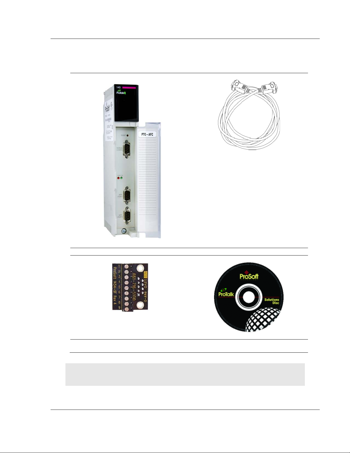
1.3.1 Package Contents
ProTalk Module
Null Modem Serial Cable
1454-9F DB-9 Female to 9 Pos Screw Terminal
adapter (Serial protocol modules only)
ProSoft Solutions CD
Note: The DB-9 Female to 5 Pos Screw Terminal adapter is not required on Ethernet modules and
is therefore not included in the carton with these types of modules.
ProSoft Technology, Inc. Page 17 of 259
June 23, 2011
Page 18

Start Here PTQ-AFC ♦ Modicon Quantum Platform
User Manual Liquid and Gas Flow Computer for Hydrocarbon Products
Quantum Hardware
This guide assumes that you are familiar with the installation and setup of the
Quantum hardware. The following should be installed, configured, and powered
up before proceeding:
Quantum Processor
Quantum rack
Quantum power supply
Quantum Modbus Plus Network Option Module (NOM Module) (optional)
Quantum to PC programming hardware
NOM Ethernet or Serial connection to PC
PC and PC Software
ProSoft Technology recommends the following minimum hardware to use the
module:
Windows PC with 80486 based processor (Pentium preferred) with at least
one COM, USB, or Ethernet port
1 megabyte of system memory
Unity™ Pro PLC Programming Software, version 3.0 or later
or
Concept™ PLC Programming Software, version 2.6 or later
or
Other Quantum Programming Software
Note: ProTalk module configuration files are compatible with common Quantum programming
applications, including Unity Pro and Concept. For all other programming applications, please
contact technical support.
Page 18 of 259 ProSoft Technology, Inc.
June 23, 2011
Page 19

PTQ-AFC ♦ Modicon Quantum Platform Configuring the Processor with Unity Pro
Liquid and Gas Flow Computer for Hydrocarbon Products User Manual
2 Configuring the Processor with Unity Pro
In This Chapter
Creating a New Project.......................................................................... 20
Adding the PTQ Module to the Project .................................................. 22
Building the Project ............................................................................... 24
Connect Your PC to the Processor ....................................................... 25
Downloading the Project to the Quantum Processor ............................. 28
The following steps are designed to ensure that the processor (Quantum or
Unity) is able to transfer data successfully with the PTQ module. As part of this
procedure, you will use Unity Pro to create a project, add the PTQ module to the
project, set up data memory for the project, and then download the project to the
processor.
ProSoft Technology, Inc. Page 19 of 259
June 23, 2011
Page 20
Configuring the Processor with Unity Pro PTQ-AFC ♦ Modicon Quantum Platform
User Manual Liquid and Gas Flow Computer for Hydrocarbon Products
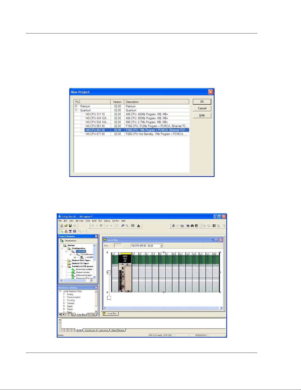
2.1 Creating a New Project
The first step is to open Unity Pro and create a new project.
1 In the New Project dialog box, choose the CPU type. In the following
illustration, the CPU is 140 CPU 651 60. Choose the processor type that
matches your own hardware configuration, if it differs from the example. Click
OK
to continue.
2 Next, add a power supply to the project. In the Project Browser, expand the
Configuration
folder, and then double-click the 1:LOCALBUS icon. This action
opens a graphical window showing the arrangement of devices in your
Quantum rack.
Page 20 of 259 ProSoft Technology, Inc.
June 23, 2011
Page 21
PTQ-AFC ♦ Modicon Quantum Platform Configuring the Processor with Unity Pro
Liquid and Gas Flow Computer for Hydrocarbon Products User Manual
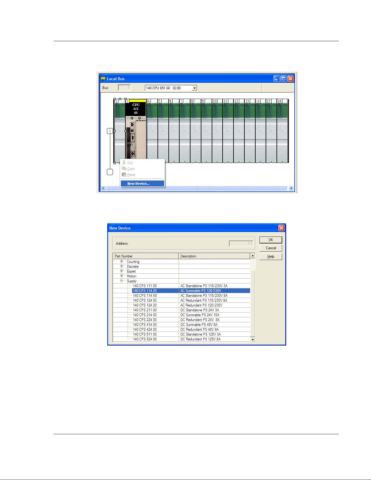
3 Select the rack position for the power supply, and then click the right mouse
button to open a shortcut menu. On the shortcut menu, choose N
EW DEVICE.
4 Expand the Supply folder, and then select your power supply from the list.
Click OK
to continue.
5 Repeat these steps to add any additional devices to your Quantum Rack.
ProSoft Technology, Inc. Page 21 of 259
June 23, 2011
Page 22
Configuring the Processor with Unity Pro PTQ-AFC ♦ Modicon Quantum Platform
User Manual Liquid and Gas Flow Computer for Hydrocarbon Products
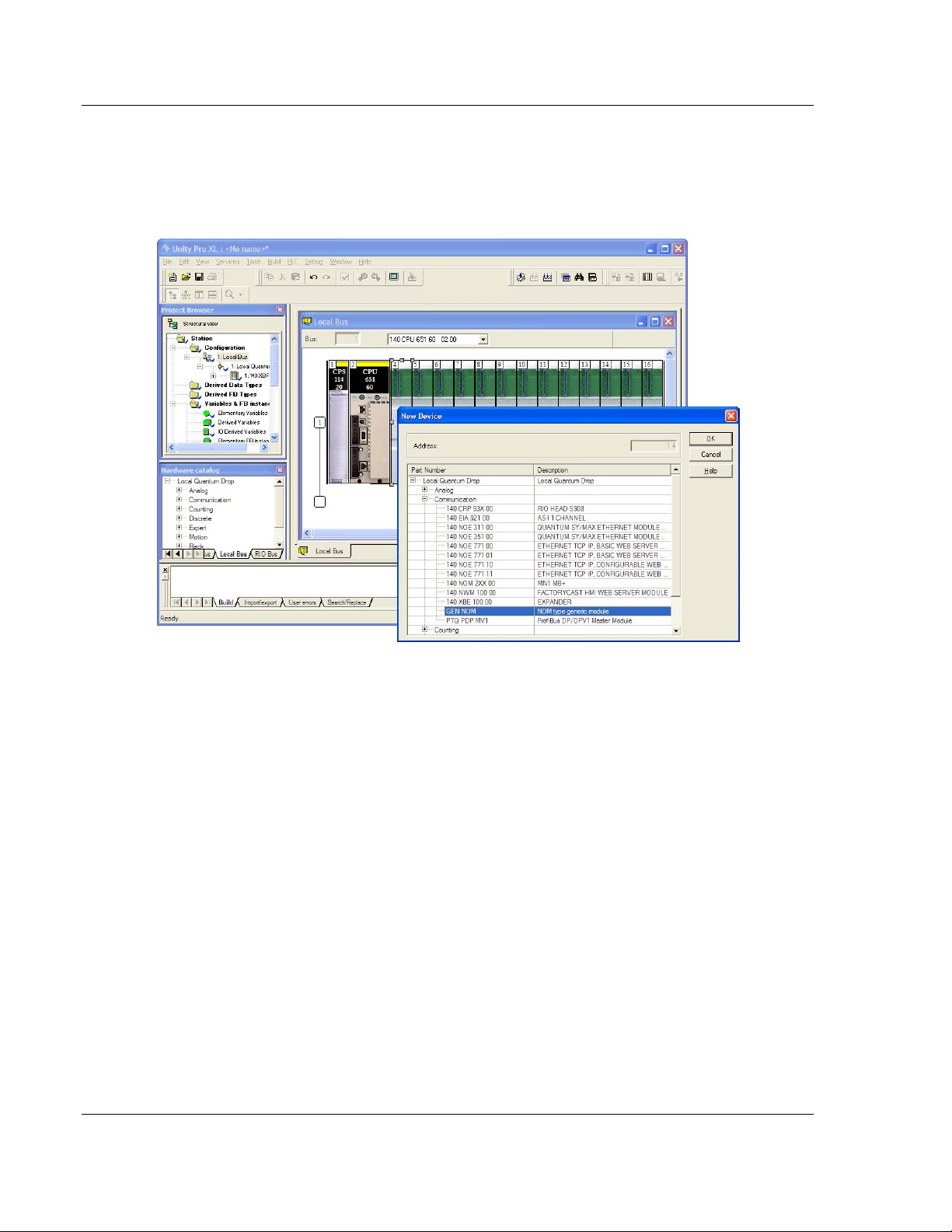
2.2 Adding the PTQ Module to the Project
1 Expand the Communication tree, and select GEN NOM. This module type
provides extended communication capabilities for the Quantum system, and
allows communication between the PLC and the PTQ module without
requiring additional programming.
Page 22 of 259 ProSoft Technology, Inc.
June 23, 2011
Page 23
PTQ-AFC ♦ Modicon Quantum Platform Configuring the Processor with Unity Pro
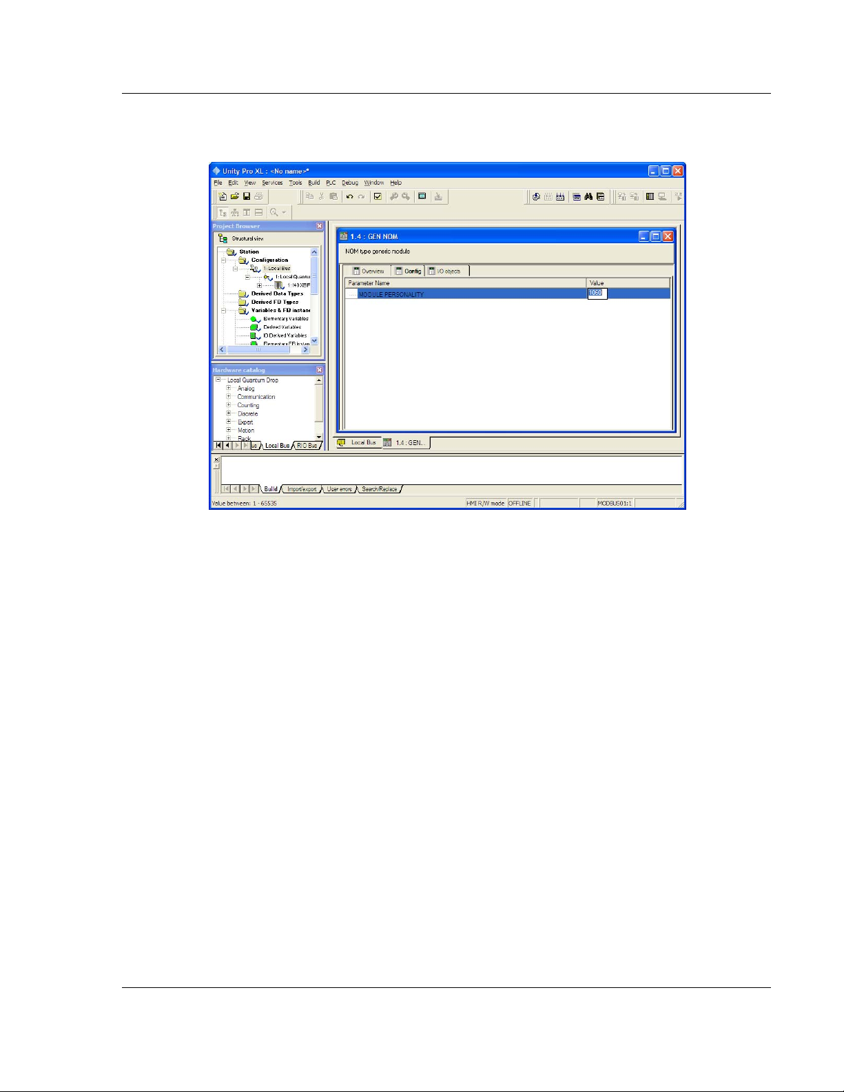
Liquid and Gas Flow Computer for Hydrocarbon Products User Manual
2 Next, enter the module personality value. The correct value for ProTalk
modules is 1060 decimal (0424 hex).
3 Before you can save the project in Unity Pro, you must validate the
modifications. Open the E
DIT menu, and then choose VALIDATE. If no errors
are reported, you can save the project.
4 S
AVE the project.
ProSoft Technology, Inc. Page 23 of 259
June 23, 2011
Page 24
Configuring the Processor with Unity Pro PTQ-AFC ♦ Modicon Quantum Platform
User Manual Liquid and Gas Flow Computer for Hydrocarbon Products
2.3 Building the Project
Whenever you update the configuration of your PTQ module or the processor,
you must import the changed configuration from the module, and then build
(compile) the project before downloading it to the processor.
Note: The following steps show you how to build the project in Unity Pro. This is not intended to
provide detailed information on using Unity Pro, or debugging your programs. Refer to the
documentation for your processor and for Unity Pro for specialized information.
To build (compile) the project:
1 Review the elements of the project in the Project Browser.
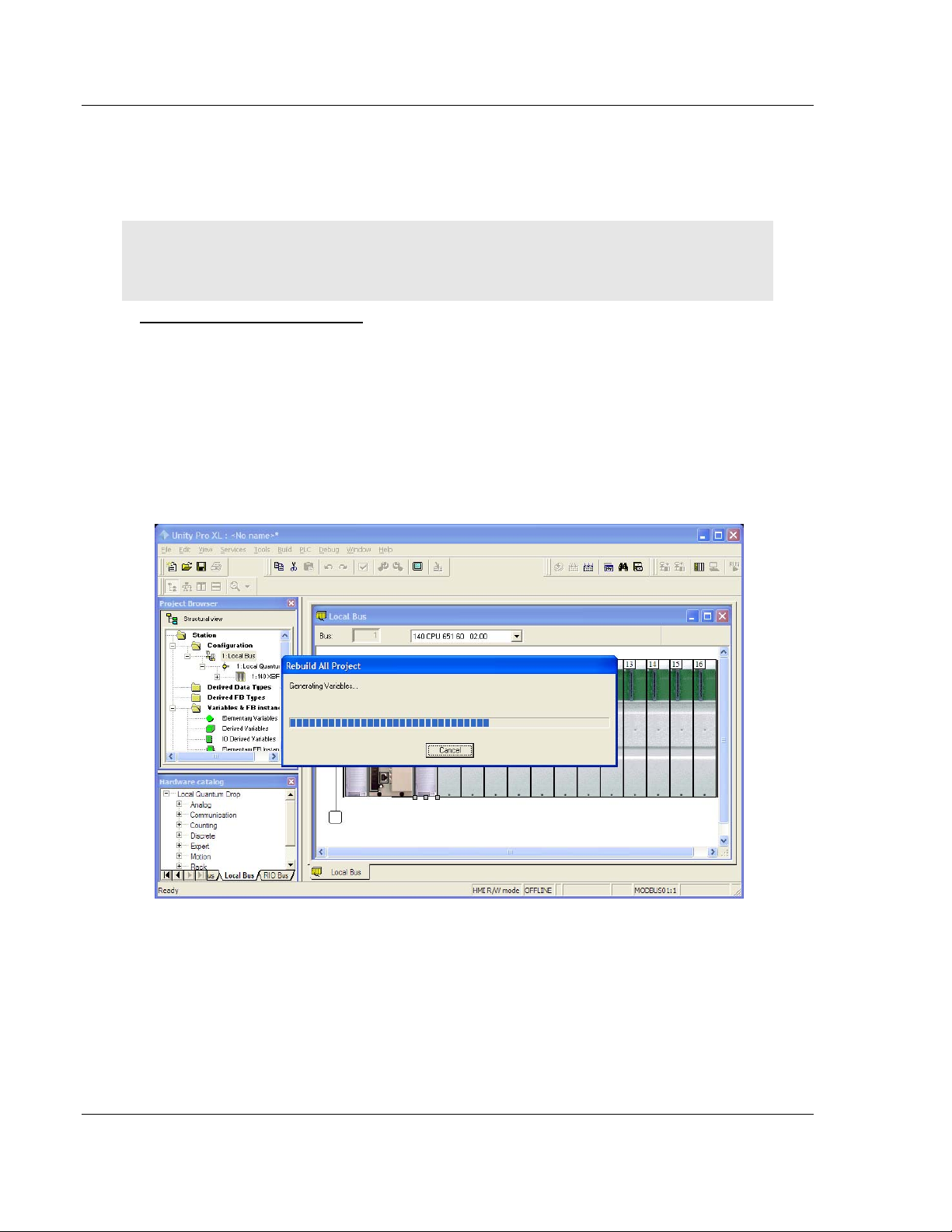
2 When you are satisfied that you are ready to download the project, open the
B
UILD menu, and then choose REBUILD ALL PROJECT. This action builds
(compiles) the project into a form that the processor can use to execute the
instructions in the project file. This task may take several minutes, depending
on the complexity of the project and the resources available on your PC.
3 As the project is built, Unity Pro reports its process in a Progress
with details appearing in a pane at the bottom of the window. The following
illustration shows the build process under way.
dialog box,
After the build process is completed successfully, the next step is to download
the compiled project to the processor.
Page 24 of 259 ProSoft Technology, Inc.
June 23, 2011
Page 25
PTQ-AFC ♦ Modicon Quantum Platform Configuring the Processor with Unity Pro
Liquid and Gas Flow Computer for Hydrocarbon Products User Manual
2.4 Connect Your PC to the Processor
The next step is to connect to the processor so that you can download the project
file. The processor uses this project file to communicate over the backplane to
modules identified in the project file.
Note: If you have never connected from the PC to your processor before, you must verify that the
necessary port drivers are installed and available to Unity Pro.
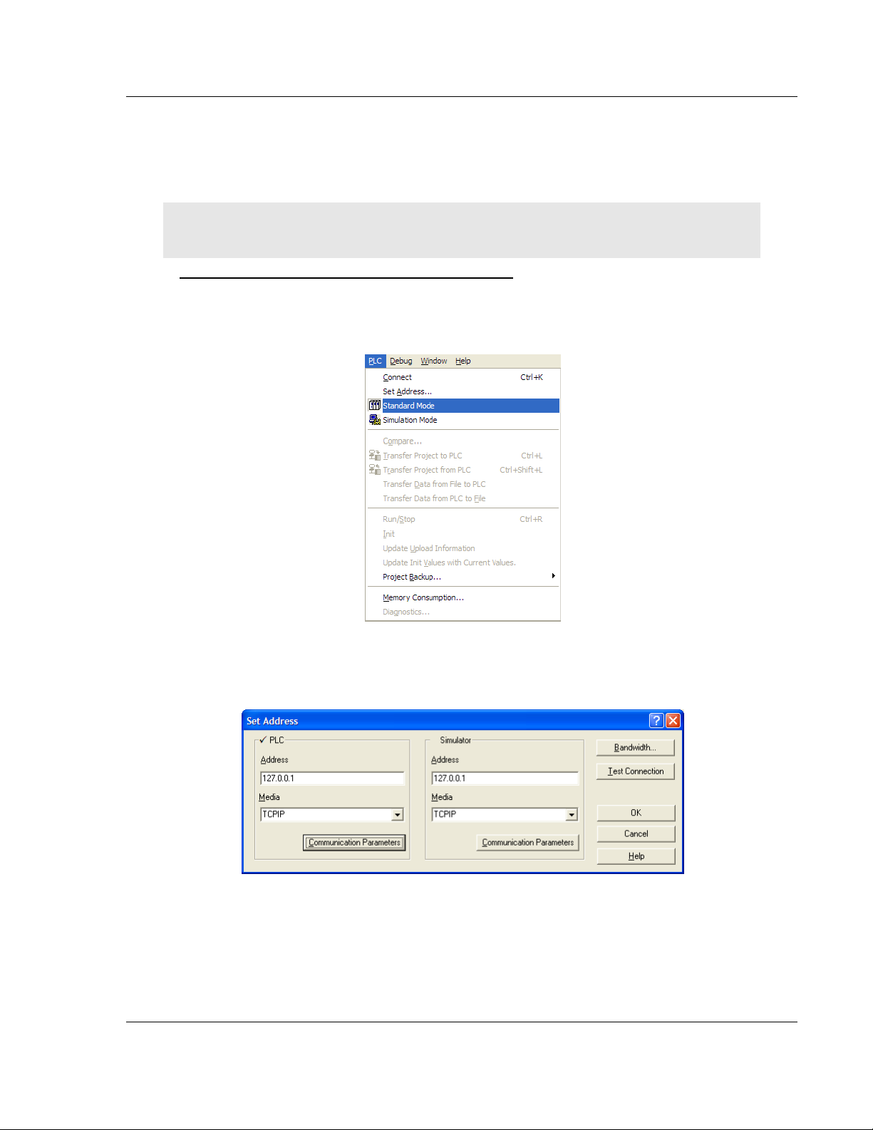
To verify address and driver settings in Unity Pro
1 Open the PLC menu, and choose STANDARD MODE. This action turns off the
PLC Simulator, and allows you to communicate directly with the Quantum or
Unity hardware.
2 Open the PLC
Address dialog box. Open the M
menu, and choose SET ADDRESS... This action opens the Set
EDIA dropdown list and choose the
connection type to use (TCPIP or USB).
ProSoft Technology, Inc. Page 25 of 259
June 23, 2011
Page 26
Configuring the Processor with Unity Pro PTQ-AFC ♦ Modicon Quantum Platform
User Manual Liquid and Gas Flow Computer for Hydrocarbon Products
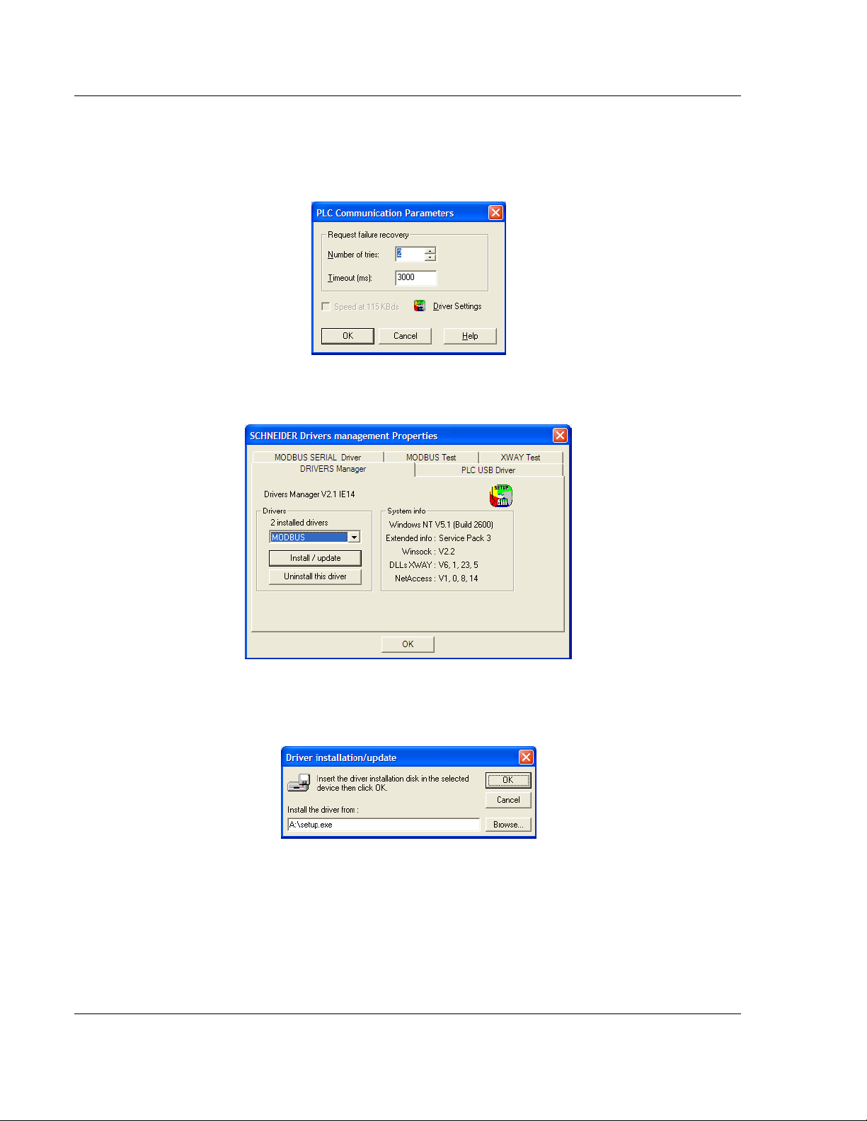
3 If the MEDIA dropdown list does not contain the connection method you wish
to use, click the C
OMMUNICATION PARAMETERS button in the PLC area of the
dialog box. This action opens the PLC Communication Parameters dialog
box.
4 Click the D
RIVER SETTINGS button to open the SCHNEIDER Drivers
management Properties dialog box.
5 Click the I
NSTALL/UPDATE button to specify the location of the Setup.exe file
containing the drivers to use. You will need your Unity Pro installation disks
for this step.
6 Click the B
ROWSE button to locate the Setup.exe file to execute, and then
execute the setup program. After the installation, restart your PC if you are
prompted to do so. Refer to your Schneider Electric documentation for more
information on installing drivers for Unity Pro.
Page 26 of 259 ProSoft Technology, Inc.
June 23, 2011
Page 27
PTQ-AFC ♦ Modicon Quantum Platform Configuring the Processor with Unity Pro
Liquid and Gas Flow Computer for Hydrocarbon Products User Manual
2.4.1 Connecting to the Processor with TCPIP
The next step is to download (copy) the project file to the processor. The
following steps demonstrate how to use an Ethernet cable connected from the
Processor to your PC through an Ethernet hub or switch. Other connection
methods may also be available, depending on the hardware configuration of your
processor, and the communication drivers installed in Unity Pro.
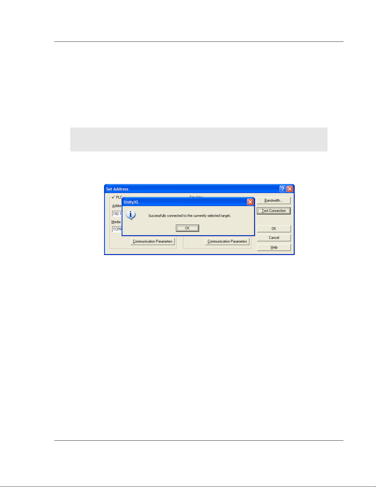
1 If you have not already done so, connect your PC and the processor to an
Ethernet hub.
2 Open the PLC
Important: Notice that the Set Address dialog box is divided into two areas. Enter the address
and media type in the PLC area of the dialog box, not the Simulator area.
3 Enter the IP address in the address field. In the MEDIA dropdown list, choose
TCPIP.
4 Click the
menu, and then choose SET ADDRESS.
TEST CONNECTION button to verify that your settings are correct.
ProSoft Technology, Inc. Page 27 of 259
June 23, 2011
Page 28
Configuring the Processor with Unity Pro PTQ-AFC ♦ Modicon Quantum Platform
User Manual Liquid and Gas Flow Computer for Hydrocarbon Products
2.5 Downloading the Project to the Quantum Processor
1 Open the PLC menu and then choose CONNECT. This action opens a
connection between the Unity Pro software and the processor, using the
address and media type settings you configured in the previous step.
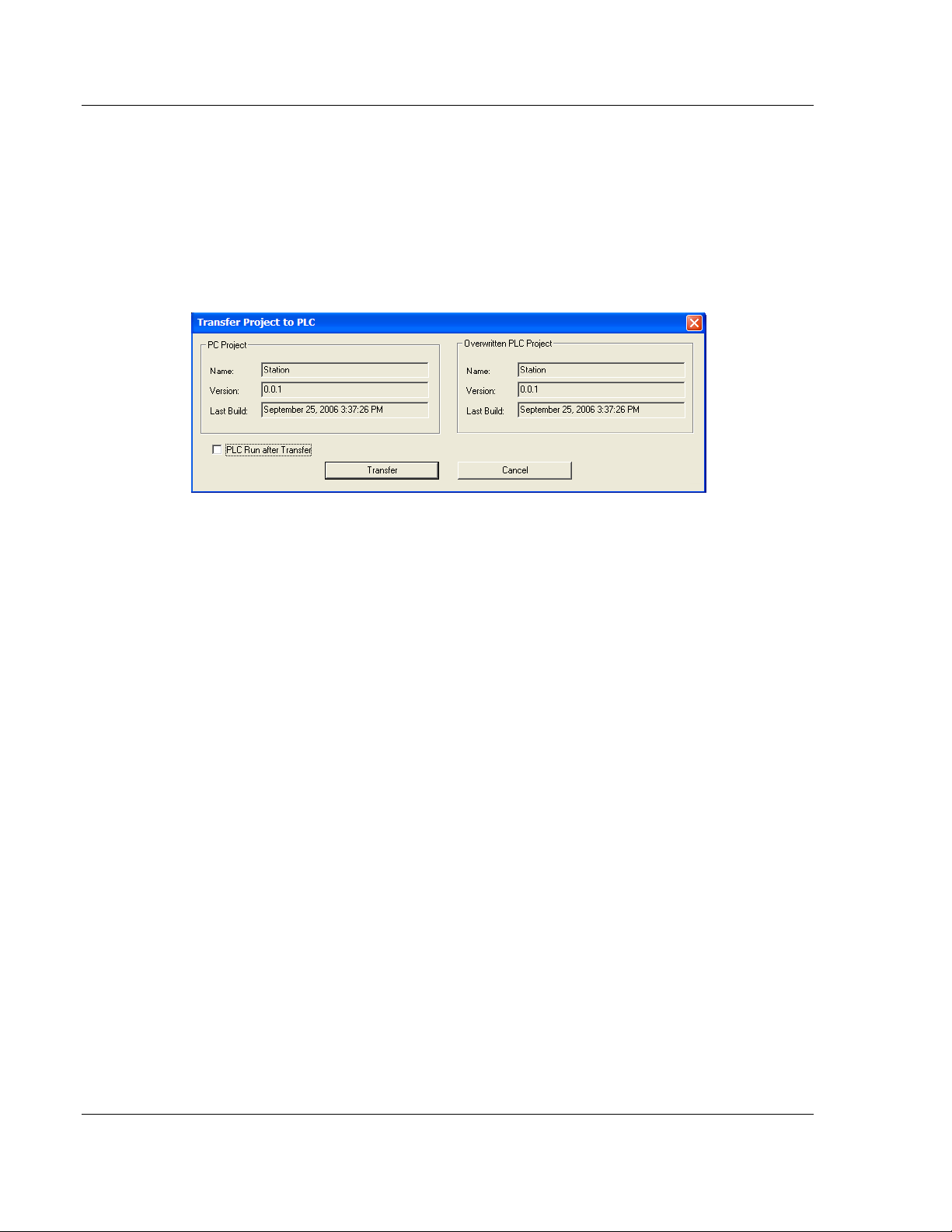
2 On the PLC
the
TRANSFER PROJECT TO PLC dialog box. If you would like the PLC to go to
"Run" mode immediately after the transfer is complete, select (check) the
PLC
RUN AFTER TRANSFER check box.
3 Click the T
project is transferred, Unity Pro reports its process in a P
with details appearing in a pane at the bottom of the window.
When the transfer is complete, place the processor in Run mode. The processor
will start scanning your process logic application.
menu, choose TRANSFER PROJECT TO PLC. This action opens
RANSFER button to download the project to the processor. As the
ROGRESS dialog box,
Page 28 of 259 ProSoft Technology, Inc.
June 23, 2011
Page 29

PTQ-AFC ♦ Modicon Quantum Platform Configuring the Processor with Concept
Liquid and Gas Flow Computer for Hydrocarbon Products User Manual
3 Configuring the Processor with Concept
In This Chapter
Information for Concept Version 2.6 Users ............................................ 30
Creating a New Project.......................................................................... 32
Adding the PTQ Module to the Project .................................................. 35
Setting up Data Memory in Project ........................................................ 38
Downloading the Project to the Processor............................................. 41
Verifying Successful Download ............................................................. 43
The following steps are designed to ensure that the processor is able to transfer
data successfully with the PTQ module. As part of this procedure, you will use
Concept configuration software from Schneider Electric to create a project, add
the PTQ module to the project, set up data memory for the project, and then
download the project to the processor.
Important Note: Concept software does not report whether the PTQ module is present in the rack,
and therefore is not able to report the health status of the module when the module is online with
the Quantum processor. Please consider this when monitoring the status of the PTQ module.
ProSoft Technology, Inc. Page 29 of 259
June 23, 2011
Page 30
Configuring the Processor with Concept PTQ-AFC ♦ Modicon Quantum Platform
User Manual Liquid and Gas Flow Computer for Hydrocarbon Products
3.1 Information for Concept Version 2.6 Users
This guide uses Concept PLC Programming Software version 2.6 to configure
the Quantum PLC. The ProTalk installation CD includes MDC module
configuration files that help document the PTQ installation. Although not required,
these files should be installed before proceeding to the next section.
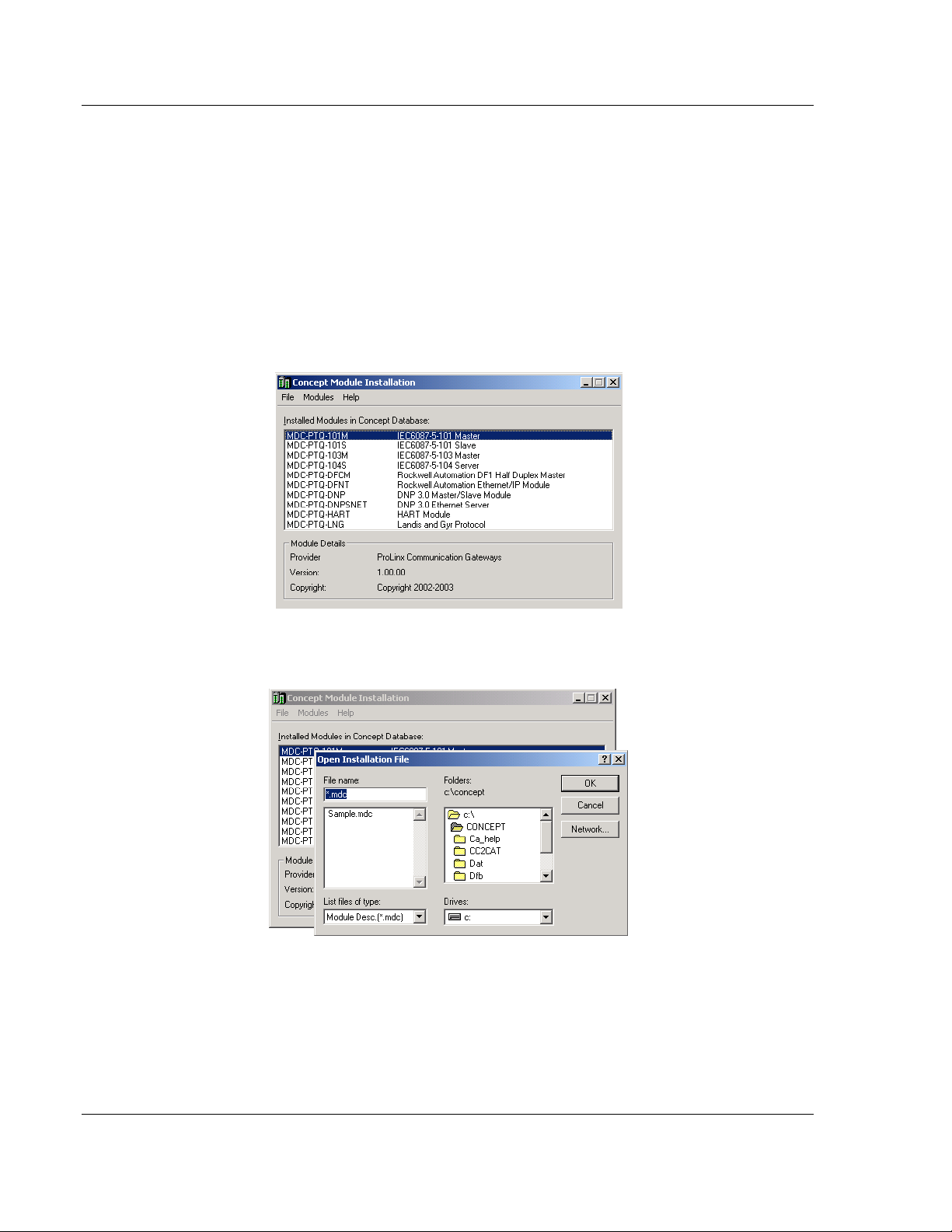
3.1.1 Installing MDC Configuration Files
1 From a PC with Concept 2.6 installed, choose START / PROGRAMS / CONCEPT
/ MODCONNECT TOOL.
This action opens the Concept Module Installation dialog box.
2 Choose F
ILE / OPEN INSTALLATION FILE.
This action opens the Open Installation File dialog box:
3 If you are using a Quantum processor, you will need the MDC files. In the
Open Installation File dialog box, navigate to the MDC Files directory on the
ProTalk CD.
4 Choose the MDC file and help file for your version of Concept:
o Concept 2.6 users: select PTQ_2_60.mdc and PTQMDC.hlp
o Concept 2.5 users: select PTQ_2_50.mdc and PTQMDC.hlp.
Page 30 of 259 ProSoft Technology, Inc.
June 23, 2011
Page 31

PTQ-AFC ♦ Modicon Quantum Platform Configuring the Processor with Concept
Liquid and Gas Flow Computer for Hydrocarbon Products User Manual
Select the files that go with the Concept version you are using, and then click
OK. This action opens the Add New Modules dialog box.
5 Click the
process. Click Y
ADD ALL button. A series of message boxes may appear during this
ES or OK for each message that appears.
6 When the process is complete, open the F
your changes.
ILE menu and choose EXIT to save
ProSoft Technology, Inc. Page 31 of 259
June 23, 2011
Page 32

Configuring the Processor with Concept PTQ-AFC ♦ Modicon Quantum Platform
User Manual Liquid and Gas Flow Computer for Hydrocarbon Products
3.2 Creating a New Project
This phase of the setup procedure must be performed on a computer that has
the Concept configuration software installed.
1 From your computer, choose S
CONCEPT. This action opens the Concept window.
2 Open the File menu, and then choose N
PLC Configuration dialog box.
TART / PROGRAMS / CONCEPT V2.6 XL.EN /
EW PROJECT. This action opens the
Page 32 of 259 ProSoft Technology, Inc.
June 23, 2011
Page 33

PTQ-AFC ♦ Modicon Quantum Platform Configuring the Processor with Concept
Liquid and Gas Flow Computer for Hydrocarbon Products User Manual
3 In the list of options on the left side of this dialog box, double-click the PLC
SELECTION folder. This action opens the PLC Selection dialog box.
4 In the CPU/Executive pane, use the scroll bar to locate and select the PLC to
configure.
ProSoft Technology, Inc. Page 33 of 259
June 23, 2011
Page 34

Configuring the Processor with Concept PTQ-AFC ♦ Modicon Quantum Platform
User Manual Liquid and Gas Flow Computer for Hydrocarbon Products
5 Click OK. This action opens the PLC Configuration dialog box, populated with
the correct values for the PLC you selected.
6 Make a note of the holding registers for the module. You will need this
information when you modify your application. The Holding Registers are
displayed in the PLC Memory Partition pane of the
PLC Configuration dialog
box.
Page 34 of 259 ProSoft Technology, Inc.
June 23, 2011
Page 35

PTQ-AFC ♦ Modicon Quantum Platform Configuring the Processor with Concept
Liquid and Gas Flow Computer for Hydrocarbon Products User Manual
3.3 Adding the PTQ Module to the Project
1 In the list of options on the left side of the PLC Configuration dialog box,
double-click
I/O MAP. This action opens the I/O Map dialog box.
2 Click the E
DIT button to open the Local Quantum Drop dialog box. This dialog
box is where you identify rack and slot locations.
ProSoft Technology, Inc. Page 35 of 259
June 23, 2011
Page 36

Configuring the Processor with Concept PTQ-AFC ♦ Modicon Quantum Platform
User Manual Liquid and Gas Flow Computer for Hydrocarbon Products
3 Click the MODULE button next to the rack/slot position where the ProTalk
module will be installed. This action opens the I/O Module Selection dialog
box.
4 In the Modules
module, and then click OK.
pane, use the scroll bar to locate and select the ProTalk
This action copies the description of the ProTalk
module next to the assigned rack and slot number of the Local Quantum
Drop dialog box.
Page 36 of 259 ProSoft Technology, Inc.
June 23, 2011
Page 37

PTQ-AFC ♦ Modicon Quantum Platform Configuring the Processor with Concept
Liquid and Gas Flow Computer for Hydrocarbon Products User Manual
5 Repeat steps 3 through 5 for each ProTalk module you plan to install. When
you have finished installing your ProTalk modules, click OK
settings. Click Y
ES to confirm your settings.
to save your
Tip: Select a module, and then click the Help on Module button for help pages.
ProSoft Technology, Inc. Page 37 of 259
June 23, 2011
Page 38

Configuring the Processor with Concept PTQ-AFC ♦ Modicon Quantum Platform
User Manual Liquid and Gas Flow Computer for Hydrocarbon Products
3.4 Setting up Data Memory in Project
1 In the list of options on the left side of the PLC Configuration dialog box,
double-click S
PECIALS.
2 This action opens the Specials
dialog box.
Page 38 of 259 ProSoft Technology, Inc.
June 23, 2011
Page 39

PTQ-AFC ♦ Modicon Quantum Platform Configuring the Processor with Concept
Liquid and Gas Flow Computer for Hydrocarbon Products User Manual
Selecting the Time of Day
1 Select (check) the Time of Day box, and then enter the value 00001 as
shown in the following illustration. This value sets the first time of day register
to 400001.
2 Click OK
to save your settings and close the Specials dialog box.
Saving your project
1 In the PLC Configuration dialog box, choose F
ILE / SAVE PROJECT AS.
ProSoft Technology, Inc. Page 39 of 259
June 23, 2011
Page 40

Configuring the Processor with Concept PTQ-AFC ♦ Modicon Quantum Platform
User Manual Liquid and Gas Flow Computer for Hydrocarbon Products
2 This action opens the Save Project As dialog box.
3 Name the project, and then click OK
to save the project to a file.
Page 40 of 259 ProSoft Technology, Inc.
June 23, 2011
Page 41

PTQ-AFC ♦ Modicon Quantum Platform Configuring the Processor with Concept
Liquid and Gas Flow Computer for Hydrocarbon Products User Manual
3.5 Downloading the Project to the Processor
Next, download (copy) the project file to the Quantum Processor.
1 Use the null modem cable to connect your PC’s serial port to the Quantum
processor, as shown in the following illustration.
Note: You can use a Modbus Plus Network Option Module (NOM Module) module in place of the
serial port if necessary.
2 Open the PLC menu, and then choose CONNECT.
3 In the PLC Configuration dialog box, open the O
choose C
ONNECT. This action opens the Connect to PLC dialog box.
NLINE menu, and then
4 Leave the default settings as shown and click OK.
Note: Click OK to dismiss any message boxes that appear during the connection process.
ProSoft Technology, Inc. Page 41 of 259
June 23, 2011
Page 42

Configuring the Processor with Concept PTQ-AFC ♦ Modicon Quantum Platform
User Manual Liquid and Gas Flow Computer for Hydrocarbon Products
5 In the PLC Configuration window, open the ONLINE menu, and then choose
D
OWNLOAD. This action opens the Download Controller dialog box.
6 Click A
that the controller is running, click Y
LL, and then click DOWNLOAD. If a message box appears indicating
ES to shut down the controller. The
Download Controller dialog box displays the status of the download as shown
in the following illustration.
7 When the download is complete, you will be prompted to restart the
controller. Click Y
ES to restart the controller.
Page 42 of 259 ProSoft Technology, Inc.
June 23, 2011
Page 43

PTQ-AFC ♦ Modicon Quantum Platform Configuring the Processor with Concept
Liquid and Gas Flow Computer for Hydrocarbon Products User Manual
3.6 Verifying Successful Download
The final step is to verify that the configuration changes you made were received
successfully by the module, and to make some adjustments to your settings.
1 In the PLC Configuration window, open the O
O
NLINE CONTROL PANEL. This action opens the Online Control Panel dialog
box.
2 Click the S
dialog box.
ET CLOCK button to open the Set Controller’s Time of Day Clock
NLINE menu, and then choose
3 Click the W
this dialog box. Click OK
RITE PANEL button. This action updates the date and time fields in
to close this dialog box and return to the previous
window.
4 Click C
5 In the PLC Configuration window, open the O
R
LOSE to close the Online Control Panel dialog box.
NLINE menu, and then choose
EFERENCE DATA EDITOR. This action opens the Reference Data Editor
dialog box. On this dialog box, you will add preset values to data registers
that will later be monitored in the ProTalk module.
ProSoft Technology, Inc. Page 43 of 259
June 23, 2011
Page 44

Configuring the Processor with Concept PTQ-AFC ♦ Modicon Quantum Platform
User Manual Liquid and Gas Flow Computer for Hydrocarbon Products
6 Place the cursor over the first address field, as shown in the following
illustration.
7 In the PLC Configuration window, open the T
choose
INSERT ADDRESSES. This action opens the Insert addresses dialog
EMPLATES menu, and then
box.
8 On the Insert Addresses dialog box, enter the values shown in the following
illustration, and then click OK.
Page 44 of 259 ProSoft Technology, Inc.
June 23, 2011
Page 45

PTQ-AFC ♦ Modicon Quantum Platform Configuring the Processor with Concept
Liquid and Gas Flow Computer for Hydrocarbon Products User Manual
9 Notice that the template populates the address range, as shown in the
following illustration. Place your cursor as shown in the first blank address
field below the addresses you just entered.
10 Repeat steps 6 through 9, using the values in the following illustration:
11 In the PLC Configuration window, open the O
ANIMATE. This action opens the RDE Template dialog box, with animated
values in the Value
field.
NLINE menu, and then choose
12 Verify that values shown are cycling, starting from address 400065 and up.
ProSoft Technology, Inc. Page 45 of 259
June 23, 2011
Page 46

Configuring the Processor with Concept PTQ-AFC ♦ Modicon Quantum Platform
User Manual Liquid and Gas Flow Computer for Hydrocarbon Products
13 In the PLC Configuration window, open the TEMPLATES menu, and then
choose S
AVE TEMPLATE AS. Name the template ptqclock, and then click OK
to save the template.
14 In the PLC Configuration window, open the O
ISCONNECT. At the disconnect message, click YES to confirm your choice.
D
NLINE menu, and then choose
At this point, you have successfully
Created and downloaded a Quantum project to the PLC
Preset values in data registers that will later be monitored in the ProTalk
module.
You are now ready to complete the installation and setup of the ProTalk module.
Page 46 of 259 ProSoft Technology, Inc.
June 23, 2011
Page 47

PTQ-AFC ♦ Modicon Quantum Platform Configuring the Processor with ProWORX
Liquid and Gas Flow Computer for Hydrocarbon Products User Manual
4 Configuring the Processor with ProWORX
When you use ProWORX 32 software to configure the processor, use the
example SAF file provided on the ProTalk Solutions CD-ROM.
Important Note: ProWORX software does not report whether the PTQ module is present in the
rack, and therefore is not able to report the health status of the module when the module is online
with the Quantum processor. Please consider this when monitoring the status of the PTQ module.
1 Run the SCHNEIDER_ALLIANCES.EXE application that is installed with the
ProWORX 32 software:
2 Click on I
MPORT…
ProSoft Technology, Inc. Page 47 of 259
June 23, 2011
Page 48

Configuring the Processor with ProWORX PTQ-AFC ♦ Modicon Quantum Platform
User Manual Liquid and Gas Flow Computer for Hydrocarbon Products
3 Select the .SAF File that is located on the CD-ROM shipped with the PTQ
module.
4 After you click on O
I/O
SERIES as QUANTUM):
PEN you should see the PTQ modules imported (select
Page 48 of 259 ProSoft Technology, Inc.
June 23, 2011
Page 49

PTQ-AFC ♦ Modicon Quantum Platform Configuring the Processor with ProWORX
Liquid and Gas Flow Computer for Hydrocarbon Products User Manual
Now you can close the Schneider alliances application and run the ProWORX 32
software. At the Traffic Cop section, select the PTQ module to be inserted at the
slot:
ProSoft Technology, Inc. Page 49 of 259
June 23, 2011
Page 50

Configuring the Processor with ProWORX PTQ-AFC ♦ Modicon Quantum Platform
User Manual Liquid and Gas Flow Computer for Hydrocarbon Products
Page 50 of 259 ProSoft Technology, Inc.
June 23, 2011
Page 51

PTQ-AFC ♦ Modicon Quantum Platform Setting Up the ProTalk Module
Liquid and Gas Flow Computer for Hydrocarbon Products User Manual
5 Setting Up the ProTalk Module
In This Chapter
Installing the ProTalk Module in the Quantum Rack .............................. 52
Connect the PC to the ProTalk Configuration/Debug Port .................... 54
After you complete the following procedures, the ProTalk module will actively be
transferring data bi-directionally with the processor.
ProSoft Technology, Inc. Page 51 of 259
June 23, 2011
Page 52

Setting Up the ProTalk Module PTQ-AFC ♦ Modicon Quantum Platform
User Manual Liquid and Gas Flow Computer for Hydrocarbon Products
5.1 Installing the ProTalk Module in the Quantum Rack
5.1.1 Verifying Jumper Settings
ProTalk modules are configured for RS-232 serial communications by default. To
use RS-422 or RS-485, you must change the jumpers.
The jumpers are located on the back of the module as shown in the following
illustration:
5.1.2 Inserting the 1454-9F connector
Insert the 1454-9F connector as shown. Wiring locations are shown in the table:
Page 52 of 259 ProSoft Technology, Inc.
June 23, 2011
Page 53

PTQ-AFC ♦ Modicon Quantum Platform Setting Up the ProTalk Module
Liquid and Gas Flow Computer for Hydrocarbon Products User Manual
5.1.3 Installing the ProTalk Module in the Quantum Rack
1 Place the Module in the Quantum Rack. The ProTalk module must be placed
in the same rack as the processor.
2 Tilt the module at a 45 angle and align the pegs at the top of the module with
slots on the backplane.
3 Push the module into place until it seats firmly in the backplane.
Caution: The PTQ module is hot-swappable, meaning that you can install and remove it while the
rack is powered up. You should not assume that this is the case for all types of modules unless the
user manual for the product explicitly states that the module is hot-swappable. Failure to observe
this precaution could result in damage to the module and any equipment connected to it.
ProSoft Technology, Inc. Page 53 of 259
June 23, 2011
Page 54

Setting Up the ProTalk Module PTQ-AFC ♦ Modicon Quantum Platform
User Manual Liquid and Gas Flow Computer for Hydrocarbon Products
5.2 Connect the PC to the ProTalk Configuration/Debug Port
Make sure you have exited the Quantum programming software before
performing these steps. This action will avoid serial port conflict.
1 Using the supplied Null Modem cable, connect your PC to the
Configuration/Debug port on the ProTalk module as shown
2 Click the Windows S
TART button, then choose PROGRAMS / ACCESSORIES /
COMMUNICATIONS / HYPERTERMINAL.
3 In the HyperTerminal window, enter a connection name, for example ProSoft
Module, and then click OK.
This action opens the Connect To dialog box.
Page 54 of 259 ProSoft Technology, Inc.
June 23, 2011
Page 55

PTQ-AFC ♦ Modicon Quantum Platform Setting Up the ProTalk Module
Liquid and Gas Flow Computer for Hydrocarbon Products User Manual
4 In the Connect Using field, ensure that the com port matches the port on your
PC to which you connected the Null Modem cable, and then click OK.
This
action opens the COMx Properties dialog box.
5 Verify that the settings match those shown in the example above, and then
click OK.
HyperTerminal
6 In the HyperTerminal window, press [?].
Configuration/Debug menu.
If your port settings are configured correctly, you will return to the
window.
This action opens the module’s
5.2.1 Troubleshooting AFC Manager Connection Problems
If AFC Manager has trouble making a connection to the AFC’s Primary Slave:
1 Check your cabling. You must connect a null-modem cable between the
COM port on your PC and the serial port on the module.
2 Connect to the module’s Configuration/Debug port if possible. If you try to
connect to another of the module’s ports, the AFC’s configuration may have
the Primary Slave hidden at that port. At the Configuration/Debug port the
Primary Slave is always visible.
3 Double-check your communications settings via Communications / Local
Port Settings. You must set up your COM port to match the settings of the
AFC’s port. By default the AFC sets up its Configuration/Debug port as: Slave
address 244, 9600 baud, no parity, 8 data bits, 1 stop bit, RTU mode; so use
those settings unless the AFC’s default configuration has been changed. Be
sure that you are selecting the correct COM port on your PC, especially if you
are using a USB serial adapter as those adapters may be assigned to
different COM ports at different times.
4 Ensure that the COM port on your PC is not in use by another application,
such as HyperTerminal. If the port is held by another application, then AFC
Manager will not be able to use it.
ProSoft Technology, Inc. Page 55 of 259
June 23, 2011
Page 56

Setting Up the ProTalk Module PTQ-AFC ♦ Modicon Quantum Platform
User Manual Liquid and Gas Flow Computer for Hydrocarbon Products
Page 56 of 259 ProSoft Technology, Inc.
June 23, 2011
Page 57

PTQ-AFC ♦ Modicon Quantum Platform Quick Start
Liquid and Gas Flow Computer for Hydrocarbon Products User Manual
6 Quick Start
In This Chapter
Install AFC Manager .............................................................................. 58
Starting AFC Manager ........................................................................... 59
Using AFC Manager .............................................................................. 60
Ladder Logic Implementation ................................................................ 66
Setting the Wallclock ............................................................................. 68
Module Initialization ............................................................................... 69
Meter Channel Functionality .................................................................. 70
Modbus Database ................................................................................. 78
Modbus Communication ........................................................................ 85
Accumulators ......................................................................................... 90
Archives ................................................................................................. 96
Events ................................................................................................. 114
Security (Passwords) .......................................................................... 129
This section provides a general overview of the steps required to install and
configure the module. You should read the AFC Manager User Manual to obtain
a clear understanding of the steps outlined in this section.
ProSoft Technology, Inc. Page 57 of 259
June 23, 2011
Page 58

Quick Start PTQ-AFC ♦ Modicon Quantum Platform
User Manual Liquid and Gas Flow Computer for Hydrocarbon Products
6.1 Install AFC Manager
The AFC Manager application is included on the CD-ROM shipped with your
module. Before you can use the application, you must install it on your computer.
6.1.1 System Requirements
The following system requirements are the recommended minimum
specifications to successfully install and run AFC Manager:
Microsoft Windows compatible PC
Windows 2000 with Service Pack 2 or higher, or Windows XP Professional
with Service Pack 2 or higher, or Windows 2003.
300 mHz Pentium processor (or equivalent)
128 megabytes of RAM
20 megabytes of free disk space
Available serial port (COM port) or USB to Serial adapter cable with
necessary drivers, required for communication between AFC Manager
software and the AFC module.
DB9 adapter cable (included with module), required for connection between
PC serial port and AFC module (PTQ-AFC module does not require an
adapter).
To install the AFC Manager application:
1 Insert the ProSoft Solutions CD in your CD-ROM drive. On most computers,
a menu screen will open automatically. If you do not see a menu within a few
seconds, follow these steps:
a Click the Start button, and then choose Run.
b In the Run dialog box, click the Browse button.
c In the Browse dialog box, click "My Computer". In the list of drives,
choose the CD-ROM drive where you inserted the ProSoft Solutions CD.
d Select the file prosoft.exe, and then click Open.
e On the Run dialog box, click OK.
2 On the CD-ROM menu, click Documentation and Tools. This action opens a
Windows Explorer dialog box.
3 Open the Utilities folder, and then open the AFCManager folder.
4 Double-click the file Setup.exe. If you are prompted to restart your computer
so that files can be updated, close all open applications, and then click OK.
When your computer has finished restarting, begin again at Step 1.
5 Click OK or Yes to dismiss any confirmation dialog boxes.
6 It may take a few seconds for the installation wizard to start. Click OK on the
AFC Manager Setup dialog box to begin installing AFC Manager.
7 Follow the instructions on the installation wizard to install the program with its
default location and settings.
8 When the installation finishes, you may be prompted to restart your computer
if certain files were in use during installation. The updated files will be
installed during the restart process.
Page 58 of 259 ProSoft Technology, Inc.
June 23, 2011
Page 59

PTQ-AFC ♦ Modicon Quantum Platform Quick Start
Liquid and Gas Flow Computer for Hydrocarbon Products User Manual
6.2 Starting AFC Manager
To start AFC Manager:
1 Click the START button, and then choose PROGRAMS.
2 In the Programs menu, choose ProSoft Technology.
3 In the ProSoft Technology menu, choose AFC Manager.
ProSoft Technology, Inc. Page 59 of 259
June 23, 2011
Page 60

Quick Start PTQ-AFC ♦ Modicon Quantum Platform
User Manual Liquid and Gas Flow Computer for Hydrocarbon Products
6.3 Using AFC Manager
The AFC module is configured with configuration files that you create using AFC
Manager. A configuration file is called a Project.
6.3.1 Starting a New Project
To start a new project:
1 Start AFC MANAGER, and then open the File Menu.
2 On the File Menu, choose N
version number.
EW, and then select your module and firmware
The version number refers to the firmware version of your module. If you do
not know the firmware version number, follow these steps:
a) Open the Project menu.
b) Choose S
ITE CONFIGURATION. This action opens the Site Configuration
dialog box.
c) Click the R
EAD button. The firmware version is listed below the serial
number, in the upper right part of the dialog box.
Important: You must be connected to the module and "online" to read data from the module.
3 Follow the steps in the remainder of this User Guide to configure your module
and your AFC device.
Page 60 of 259 ProSoft Technology, Inc.
June 23, 2011
Page 61

PTQ-AFC ♦ Modicon Quantum Platform Quick Start
Liquid and Gas Flow Computer for Hydrocarbon Products User Manual
4 Before closing the program, open the File menu and choose SAVE AS, to
save your project so you can open it again later.
6.3.2 Loading an Existing project
You can open and edit a project you have previously saved. Do this if you have
started, but not completed, the configuration of your project, or if you need to
modify the settings for a project that has already been downloaded to the
module.
To load an existing project:
1 Start AFC MANAGER, and then open the File menu.
2 On the File menu, choose L
list of AFC Manager project files (AFC files) in the current folder.
3 Choose the project to load, and then click O
OAD. This action opens a dialog box that shows a
PEN.
6.3.3 Printing the Configuration Report
You can print a report of your configuration for future reference, or for archival
purposes.
To print the configuration report:
1 Open the File menu, and then select PRINT REPORT. This action opens the
Print Configuration dialog box.
2 On the Print Configuration dialog box, select (check) the items to include in
the printed report.
3 Click
Note: The size of the report depends on items you choose to include, and may require 75 pages or
more. Consider this before printing.
PRINT to send the report to your default printer.
ProSoft Technology, Inc. Page 61 of 259
June 23, 2011
Page 62

Quick Start PTQ-AFC ♦ Modicon Quantum Platform
User Manual Liquid and Gas Flow Computer for Hydrocarbon Products
6.3.4 Converting a Project
You can convert an existing project (configuration file) to use it with a different
module or firmware version. Do this if:
You want to reuse an application created for a different AFC module, for
example a project that was created for a PTQ-AFC that you want to use for
an MVI69-AFC.
You apply a firmware upgrade to a module.
To convert a project:
1 Open the File menu, and then choose OPEN.
2 Open the project (configuration file) to convert.
3 Open the Project menu, and then choose C
HANGE MODULE TYPE.
4 Choose the module type and firmware version from the menu.
5 Save your project.
Note: AFC Manager will save your updated configuration file with the same name as the file you
loaded. If you need to keep your original configuration, change the file name of your updated
configuration before saving.
Page 62 of 259 ProSoft Technology, Inc.
June 23, 2011
Page 63

PTQ-AFC ♦ Modicon Quantum Platform Quick Start
Liquid and Gas Flow Computer for Hydrocarbon Products User Manual
6.3.5 Resetting Configuration Parameters
If you have modified your project (configuration file), or if you have loaded a
configuration file from disk, but you want to start a new project, you can reset the
configuration parameters back to their defaults without having to close and
reopen the AFC Manager.
To reset configuration parameters
1 Close any dialog boxes that are open.
2 Save the configuration file you were working on, if you would like to load it
again later.
3 On the File menu, choose R
Note: This procedure has the same effect as choosing File / New / None.
If you have made changes to the configuration that have not yet been saved, a
confirmation dialog box will open.
Answer Yes to save your changes, or No to discard your changes and begin
working on a new configuration. Click Cancel to abandon the attempted action
that caused this message.
ESET.
6.3.6 Downloading the Project to the Module
1 Click PROJECT / DOWNLOAD PROJECT.
2 This action opens the Local Port Settings window. Enter the port parameters
to use, and then click D
ONE.
ProSoft Technology, Inc. Page 63 of 259
June 23, 2011
Page 64

Quick Start PTQ-AFC ♦ Modicon Quantum Platform
User Manual Liquid and Gas Flow Computer for Hydrocarbon Products
3 During the download operation, the following progress window is displayed:
4 When the file transfer is complete, the following window is displayed:
Note: The virtual slave remapping data (page 82) is not downloaded during the procedure because
it requires a separate download operation.
Troubleshooting Tip: If the AFC Manager displays an "Illegal Data Value" message, it typically
indicates an invalid meter type or product group configuration. The module does not accept a
configuration file that attempts to change a meter type or product group for a meter that is currently
enabled. Disable all meters, change the meter types and product groups, and then enable the
meters again.
6.3.7 Verifying Correct Operation
When all of the configuration steps have been completed, the module should be
ready to perform measurement calculations. To verify that the module is
configured correctly, follow these steps:
1 Enable all meters that will be used, as any meter will only perform
calculations if it is enabled. Any meter can be enabled either with ladder logic
(PTQ-AFC modules), function blocks (PTQ modules) or with AFC Manager.
2 Make sure that the wallclock is running, and that it has valid date and time
information. After power-up, the wallclock will be stopped, therefore the
module will not perform any time-scheduled operations, such as writing
period-end archives, and will not timestamp records written to the event log
until it receives a wallclock command from the ladder logic.
The sample ladder logic programs the wallclock update command upon
detecting "power-up" status from the AFC. The date/time information used is
the same as the processor, therefore you should use the configuration tool for
your processor to verify that the processor has valid date/time data. If the
processor wallclock is not valid (for example if the year = 1900), the module
will not accept the command. You may easily determine if the wallclock is
running by performing two consecutive read operations in the Meter Monitor.
3 Make sure that the meter does not have any alarms. A meter alarm may
affect flow calculation. Look at the Meter Monitor dialog box for alarms.
4 Make sure that the input parameters transferred from the processor are
correct. You can look at these values in the Meter Monitor dialog box.
Page 64 of 259 ProSoft Technology, Inc.
June 23, 2011
Page 65

PTQ-AFC ♦ Modicon Quantum Platform Quick Start
Liquid and Gas Flow Computer for Hydrocarbon Products User Manual
5 When using a pulse meter, make sure that the pulse input rollover parameter
in Meter Configuration matches the actual input rollover value used in the
high speed counter module.
ProSoft Technology, Inc. Page 65 of 259
June 23, 2011
Page 66

Quick Start PTQ-AFC ♦ Modicon Quantum Platform
User Manual Liquid and Gas Flow Computer for Hydrocarbon Products
6.4 Ladder Logic Implementation
The sample ladder logic performs tasks that are covered in the Ladder Logic
sections of this manual. The most important task is to continuously write meter
process input variables from the processor to the module, and read calculation
results from the module to the processor.
Refer to the Ladder Logic sections for instructions on how to transfer the meter
process variables from the processor to the module. Ladder logic is required to
move the process variables to the correct data file or controller tag in the
processor.
The Meter Monitor window (Process Inputs field) displays the values that are
transferred from the processor.
Page 66 of 259 ProSoft Technology, Inc.
June 23, 2011
Page 67

PTQ-AFC ♦ Modicon Quantum Platform Quick Start
Liquid and Gas Flow Computer for Hydrocarbon Products User Manual
The values calculated by the module are continuously transferred to the
processor. You can refer to the Meter Monitor window to verify results
calculated by the module.
Refer to the Ladder Logic section for more information regarding the data files
and controller tags that store the calculation results transferred from the module
(for example, accumulator, flow rate, and so on).
ProSoft Technology, Inc. Page 67 of 259
June 23, 2011
Page 68

Quick Start PTQ-AFC ♦ Modicon Quantum Platform
User Manual Liquid and Gas Flow Computer for Hydrocarbon Products
6.5 Setting the Wallclock
After power-up, the module must receive valid wallclock data from the ladder
logic to perform time-scheduled operations and to properly timestamp historical
records. The sample ladder logic automatically writes the wallclock during the
processor’s first scan (using the processor’s date and time information). You
should ensure that the processor contains valid date and time information. If it
does not, the module may not accept the wallclock block.
You can verify the wallclock information using the Meter Monitor section as
shown in the following example:
Refer to the Sample Ladder Logic section for more information on this topic.
Page 68 of 259 ProSoft Technology, Inc.
June 23, 2011
Page 69

PTQ-AFC ♦ Modicon Quantum Platform Quick Start
Liquid and Gas Flow Computer for Hydrocarbon Products User Manual
6.6 Module Initialization
When the module is powered up for the first time, both the OK and ERR BBRAM
LEDs are illuminated. This indicates that the module is in the Cold Start state and
is not yet ready to perform calculations. The following steps initialize the module:
Enable at least one meter
Set the processor to RUN mode
After these two steps are accomplished, the state is changed from Cold Start to
Released. This indicates that that module is ready to perform flow calculations.
When in the Released state, the OK LED is ON and the ERR LED is off.
When the module is ready, you will use AFC Manager to monitor meter
operation, archives, and events. The AFC Manager User Manual contains
detailed information on these tasks.
ProSoft Technology, Inc. Page 69 of 259
June 23, 2011
Page 70

Quick Start PTQ-AFC ♦ Modicon Quantum Platform
User Manual Liquid and Gas Flow Computer for Hydrocarbon Products
6.7 Meter Channel Functionality
6.7.1 Meter Channels
The number of available meter channels depends on the platform as follows:
MVI46-AFC = 8 meters
MVI56-AFC = 16 meters
MVI69-AFC = 8 meters
MVI71-AFC = 8 meters
PTQ-AFC = 16 meters
Each meter channel can be assigned as a linear meter (pulse meter) input or as
a differential meter (orifice meter) input for flow measurement using either SI or
US units. Selecting the differential meter causes the module to use the AGA 3
standards for flow calculation. Selecting the linear meter causes the module to
use the AGA 7 standard for gas flow calculation.
Each meter channel can be configured for gas or liquid (crude or refined)
product. The Product Group essentially selects the API/AGA Standards to be
used in calculating flow rates/increments.
Selecting "Gas" causes use of AGA8 and either AGA3 or AGA7 Standards.
Selecting any liquid group causes use of the API2540 Standards. "Crude/LPG"
and "Oil-Water Emulsion" use the base, "A", and "E" tables 23/24/53/54, and
"Refined Products" uses the "B" tables 23/24/53/54. "Crude/LPG" is used for
propane, butane, NGLs (natural gas liquids), and crude oils which are relatively
water-free (less than 5 per cent. "Oil-Water Emulsion" is used for crude and
NGL/LPG that might have a high concentration of water for which API MPMS
Chapter 20.1 is applicable. "Refined Products" is used for gasoline, jet fuels, and
fuel oils.
The following table provides a brief overview of the standards used according to
the Meter Type and Product Group:
Meter Type
Differential
Differential
Linear
Linear
Product Group Standards
Gas AGA8, AGA3
Liquid API2540, AGA3
Gas AGA8, AGA7
Liquid API2540, MPMS ch12.2
Note: The meter channel must be disabled in order to change its meter type and product group.
Page 70 of 259 ProSoft Technology, Inc.
June 23, 2011
Page 71

PTQ-AFC ♦ Modicon Quantum Platform Quick Start
Liquid and Gas Flow Computer for Hydrocarbon Products User Manual
6.7.2 Linear (Pulse) Meter Overview
The module typically receives the pulse count and pulse frequency values from a
high-speed counter module. The module uses these values to perform
calculations.
You can configure the primary input to be used for volume calculation. You can
configure it as Pulse Count or Pulse Frequency.
Primary Input = Pulse Count
If you select Pulse Count as the primary input, the module uses the pulse count
value transferred through the backplane as the primary input for volume
calculation. In this case, the pulse frequency will be used for flow rate calculation
only.
Primary Input = Pulse Frequency
If you select Pulse Frequency as the primary input, the module uses the pulse
frequency value transferred through the backplane as the primary input for both
flow accumulation and flow rate calculation. The pulse count value is ignored by
the module.
6.7.3 Differential (Orifice) Meter Overview
The static pressure of the gas stream can be measured either upstream of the
meter (before the differential pressure drop), or downstream of the meter (after
the pressure drop). Both AGA3 and AGA8 require the upstream static pressure
for their calculations, where:
upstream pressure = downstream pressure + differential pressure
If the pressure is measured from a downstream tap (typical), the Downstream
Static Pressure option should be set through the AFC Manager.
The module also supports the V-Cone device. You can configure V-Cone meters
and downstream selections in AFC Manager, on the Meter Configuration /
Calculation Options dialog box.
ProSoft Technology, Inc. Page 71 of 259
June 23, 2011
Page 72

Quick Start PTQ-AFC ♦ Modicon Quantum Platform
User Manual Liquid and Gas Flow Computer for Hydrocarbon Products
Primary Input = Differential Pressure
The primary input parameter configures the value used as source for the
accumulator calculation. If the parameter is set to Differential Pressure, the
module uses the differential pressure value transferred through the backplane for
accumulator calculation.
Primary Input = Flow Rate
You can configure the primary input parameter as flow rate in order to use this
value for the accumulator calculation.
Note: The flow rate can be converted to a different unit.
The AFC Manager software supports the following parameters:
Orifice Plate and Meter Tube Measured Diameter
Orifice Plate and Meter Tube Measurement Temperature
Orifice Plate and Meter Tube, Coefficient of Thermal Expansion
DP Flow Threshold (kPa)
DP Alarm Threshold (kPa)
Page 72 of 259 ProSoft Technology, Inc.
June 23, 2011
Page 73

PTQ-AFC ♦ Modicon Quantum Platform Quick Start
Liquid and Gas Flow Computer for Hydrocarbon Products User Manual
6.7.4 Gas Product Overview
The gas compressibility calculations are based on molar analysis concentrations
of up to 21 components, using the Detail Characterization Method of AGA8
(1992). The module automatically generates alarms if the sum of the molar
concentrations is not 100%
Configure the analysis settings using the AFC Manager (Meter Configuration /
Analysis Config) as follows. This window allows the selection of the
components(Component Selection Map) and stream precision (Precision and
Stream Assignment – version 2.06.000 or higher). The sample ladder logic
assumes that all components are selected so check all components at the
Component Selection Map window.
Enter the gas analysis concentrations by clicking at the Analysis button.You can
also update the concentrations through the backplane as it will be later shown at
this User Manual.
The module records events every time a molar concentration value changes. For
applications that involve gas chromatograph devices, this feature might not be
desirable because it is expected that the values should frequently change. You
can disable this feature using AFC Manager (Meter Configuration / Control
Options / Treat Analysis as Process Input).
ProSoft Technology, Inc. Page 73 of 259
June 23, 2011
Page 74

Quick Start PTQ-AFC ♦ Modicon Quantum Platform
User Manual Liquid and Gas Flow Computer for Hydrocarbon Products
6.7.5 Liquid Product Overview
The module supports applications involving crude or refined oil such as crude oil,
oil/water emulsion, propane, butane, NGLs, LPGs, gasoline, jet fuels and
lubricating oils.
When measuring liquids with density correction, density at flowing conditions is
required. This value may be provided directly as a process input, or the module
can calculate a density from the frequency provided by a densitometer device.
To use a densitometer
Follow the steps below to use a densitometer.
1 Configure it, entering all configuration parameters directly from the calibration
data sheet supplied by the densitometer manufacturer.
2 Supply the frequency output from the densitometer in Hz as a floating-point
value in the "Flowing density" process-input location over the backplane
(refer to the Backplane Communication section for your platform in the PTQAFC manual to determine the correct location). The AFC then calculates a
flowing density value, which is then validated by the range check mandated
by the "Density" values of "Process Input Scaling" of the meter configuration.
The "Scaling" sub-selection is not used against the frequency input, however;
the frequency is always input as floating-point.
Note: If using the Densitometer feature, select the Density Process Input Scaling for 4 to 20mA
and enter the densitometer frequency as a floating-point value.
Module Configuration
Density Units
The liquid density units can be expressed as:
3
Density is in kg/m
;
Relative density 60ºF/60ºF;
API gravity;
Measuring Water Diluent
For liquid measurement applications, the optional automatic calculation of Net Oil
Volume and mass based on the Sediment and Water (S&W) percent input is
supported. Only provide the S&W percent value in the specified controller
register. The module puts the gross standard (or gross clean oil), net oil and
water accumulations in separate accumulators. Refer to Net Accumulator
Calculation (page 95).
Page 74 of 259 ProSoft Technology, Inc.
June 23, 2011
Page 75

PTQ-AFC ♦ Modicon Quantum Platform Quick Start
Liquid and Gas Flow Computer for Hydrocarbon Products User Manual
6.7.6 General Features
Process Variable Interface
Process variables for each of the meter runs must be produced by the controller
for consumption by the AFC module. A versatile architecture for backplane
transfer of process variables and other data and signals allow you to easily
implement the data transfer. The sample ladder logic automatically transfers the
process variables to the module and reads the calculation results to the
processor.
Meter Scan Time
For good measurement, the process I/O must be sampled, and the flow
calculations completed quickly in order to avoid losing process information and
measurement accuracy. The process I/O scan time for the module is under one
second for all meter runs.
Note: This is time-dependent on design of the ladder logic implemented to support the two-way
data transfer between the AFC module and the controller. The meter calculation scan independent
of the process I/O scan may take longer.
Multiple Meter Accumulators
Each meter channel supports the following set of full 32-bit accumulators that
may be configured in binary or split decimal format with user-defined rollover
values:
Gross Volume
Gross Standard Volume (liquid only)
Net Volume
Mass
Water (liquid only)
Energy (gas only)
Access to the above accumulators is available directly from the two Modbus
Slave communications ports.
Product Batching
Any or all of the available meter runs may be configured for field installation that
requires shipping and/or receiving product batches of predetermined size. The
configuration utility option of selecting resettable accumulators provides a simple
way to use the power of ladder logic to design product batching, monitoring, and
control tailored to suit specific field requirements.
The Meter Signals feature can be used to create an archive or reset an
accumulator after the batch is concluded. Refer to the Ladder Logic section for
your platform for more information on using this feature.
ProSoft Technology, Inc. Page 75 of 259
June 23, 2011
Page 76

Quick Start PTQ-AFC ♦ Modicon Quantum Platform
User Manual Liquid and Gas Flow Computer for Hydrocarbon Products
Data Archiving
The module supports the archiving of data for each meter channel. Each time,
one record consisting of all the associated data is date and time stamped and
archived. This option allows for archiving each hour for 2 days (48 records per
meter run) and every day for 35 days (35 daily records per meter run) for each
meter channel. Each record consists of up to 40 process and other variables.
Archives are mapped to the local Modbus Table. Refer to Archives (page 96) for
more information about this topic.
Event Log Function
The module can log up to 1999 critical events in an Event Log File stored as a
set of easily accessible Modbus registers in non-volatile RAM. Changing critical
parameters, such as orifice plate size, Meter Base K factors, and Meter
Correction Factors, are time stamped and logged. Refer to Events for more
information about this topic.
Measurement Units
This option is provided for each meter channel to be configured with SI or US
units of measurement. Units for flow totalization (volumetric and mass) and flow
rate monitoring are configurable for each meter channel separately if the default
configuration is not applicable. Each meter channel may be configured to use
any of the standard units from liters/gallons to thousand cubic meters/barrels.
The flow rate period of each meter channel may be selected from flow rate per
second, per minute, per hour, or per day.
Page 76 of 259 ProSoft Technology, Inc.
June 23, 2011
Page 77

PTQ-AFC ♦ Modicon Quantum Platform Quick Start
Liquid and Gas Flow Computer for Hydrocarbon Products User Manual
Process Input Scaling
The module allows you to either pre-scale the process inputs via ladder logic for
use in the measurement calculations, or provide unscaled values from the analog
input modules directly. In the second case, the scaling is done internally. You can
directly enter the zero-scale, the full-scale, and the default values for each of the
process variable inputs through the configuration window.
Scaled Integer
Variable
Temperature
Pressure
Differential Pressure
Density (kg/m3)
Density (Relative Density)
Density (API)
Format Example
Two decimal places implied A value of 1342 would be equivalent
to 13.42°C
No decimal places implied for SI
units (kPa) and one decimal
place implied for U.S. units (psi).
Two decimal places implied for
inches of H2O and 3 places for
kPa
One implied decimal place A value of 5137 would be equivalent
Four implied decimal places A value of 10023 would be equivalent
Two implied decimal places A value of 8045 would be equivalent
A value of 200 would be equivalent to
200kPag
A value of 35142 would be equivalent
to 35.142kPa
to 513.7 kg/m3
to 1.0023 60F/60F.
to 80.45 API.
In the Meter Monitor window, the raw value is shown at the "Last Raw" column
and the converted values are shown at the "Scaled Avg" column.
When selecting the 4 to 20mA process input scaling, the module uses the
following ranges:
4 to 20mA
Processor
SLC
ControlLogix
CompactLogix
PLC
Quantum
Module 0% 100%
MVI46-AFC 3277 16384
MVI56-AFC 13107 65535
MVI69-AFC 6241 31206
MVI71-AFC 819 4095
PTQ-AFC 4000 20000
The module uses the configured values for zero and full scale to interpret the
process input scaling.
ProSoft Technology, Inc. Page 77 of 259
June 23, 2011
Page 78

Quick Start PTQ-AFC ♦ Modicon Quantum Platform
V
User Manual Liquid and Gas Flow Computer for Hydrocarbon Products
6.8 Modbus Database
The module supports two individual Modbus slaves (Primary and Virtual) to
optimize the polling of data from the remote SCADA system, or from the
processor (through the backplane). Refer to the Modbus Dictionary dialog box in
AFC Manager for information about Modbus addressing.
6.8.1 AFC Modbus Address Space
Addressable Modbus registers are divided into four banks as shown in the
following table.
MODBUS Address Space Allocation: Total Modbus Registers: 131,072
Primary Slave Banks
(131072 registers)
Holding Registers
From: 0
To: 65535
The first 100 registers of the virtual slave (registers 0 through 99) are predefined
to map to the first 100 registers of the primary slave. This mapping cannot be
changed. Also, the Virtual Slave Input Registers can be accessed as Virtual
Slave Holding Registers by adding 10000 to the Modbus register address; for
example, Input Register 2386 is the same as Holding Register 12386.
Input Registers
From: 0
To: 65535
irtual Slave Banks
(20,000 registers)
Holding Registers Input Registers
From: 0 From: 0
To: 9999 To: 9999
Accessing the Data
The AFC Manager provides an easy way to read and write data from both slaves
through the Modbus Master Interface.
Page 78 of 259 ProSoft Technology, Inc.
June 23, 2011
Page 79

PTQ-AFC ♦ Modicon Quantum Platform Quick Start
Liquid and Gas Flow Computer for Hydrocarbon Products User Manual
6.8.2 Primary Slave
The Primary Slave contains the main AFC database that consists of 131,072
Modbus registers. The Site and Meter configuration, as well as all live process
data and ongoing calculations are kept in the Primary Slave address space. This
address space is divided equally between the Input Register Bank (65,536
registers) and the Holding Register Bank (65,536).
The register addressing is shown in the Modbus Dictionary dialog box in AFC
Manager.
Modbus Address References
In these documents (the AFC Manager User’s Guide and the User’s Guide for
your platform) you will occasionally see Modbus address references like
Ph00018 or Mh00162. The first two characters of such references indicate how
to convert the following number into an absolute Modbus address in the module.
This table shows the possible values for the first identification character:
Address Translation ID
P
M
V
This table shows the possible values for the second identification character:
Register Bank ID
h
i
Description
Absolute Modbus address, Primary Slave
Meter-relative Modbus address, Primary Slave
Absolute Modbus address, Virtual Slave
Description
Holding register
Input register
Modbus Address Examples
Ph02000 = holding register located at address 2000 in the primary slave
Pi02000 = input register located at address 2000 in the primary slave
Mh00100 = Meter-relative holding register located at offset 100 in the block of the
primary slave that contains the data for the meter
ProSoft Technology, Inc. Page 79 of 259
June 23, 2011
Page 80

Quick Start PTQ-AFC ♦ Modicon Quantum Platform
User Manual Liquid and Gas Flow Computer for Hydrocarbon Products
Meter-relative Data
Meter-relative data starts at absolute holding register address 8000 and occupies
2000 words of data for each meter channel.
The meter-relative addresses are offsets within each meter data area. The
correct absolute address is calculated by the following formula (assumes meters
are numbered starting with 1):
(absolute address) = (2000 * (meter number-1)) + 8000 + (meter relative
address)
In the Modbus Dictionary dialog box, addresses listed for the selected meter are
absolute addresses, so you should subtract the appropriate multiple of 8000 to
calculate the meter-relative address.
Page 80 of 259 ProSoft Technology, Inc.
June 23, 2011
Page 81

PTQ-AFC ♦ Modicon Quantum Platform Quick Start
Liquid and Gas Flow Computer for Hydrocarbon Products User Manual
Example: Find the orifice diameter address for the first 5 meter channels.
The meter 1 orifice diameter registers are located at the holding register address
8162 and 8163 as follows:
8160
8162
8164
8166
8168
8170
8172
8161 Float Parameter: orifice plate: measurement temperature
8163 Float Parameter: orifice plate: measured diameter
8165 Float Parameter: orifice plate: coef of thermal expansion
8167 Float Parameter: meter tube: measurement temperature
8169 Float Parameter: meter tube: measured diameter
8171 Float Parameter: meter tube: coef of thermal expansion
8173 Float Parameter: differential pressure flow threshold
The meter-relative addresses are Mh00162 and Mh00163
The addresses for meters 1 to 5 are listed on the following table.
Meter
1
2
3
4
5
Registers
8162 and 8163
10162 and 10163
12162 and 12163
14162 and 14163
16162 and 16163
Scratchpad
The Primary Modbus Slave contains a scratchpad area that can be used to store
any data required by each application. This area is "empty" by default and
contains 6000 words of data starting at holding register 2000 in the Primary
Modbus Slave.
ProSoft Technology, Inc. Page 81 of 259
June 23, 2011
Page 82

Quick Start PTQ-AFC ♦ Modicon Quantum Platform
User Manual Liquid and Gas Flow Computer for Hydrocarbon Products
6.8.3 Virtual Slave
The module also provides a Virtual Address Space of 20,000 Modbus registers.
This address space is divided equally between the Input Register Bank (10,000
registers) and the Holding Register Bank Holding Register Bank (10,000). This is
where you can create a virtual re-map by cross-referencing any of the 130,072
Primary Slave Modbus registers to the 20,000 Modbus registers in the Virtual
Slave Banks, thereby making it easy for a SCADA Master to poll only the
necessary Modbus addresses in contiguous blocks. The virtual slave can also be
used for data polling from the processor through the backplane.
Modbus access to the Virtual Modbus Slave is disabled by default since its
Modbus address is originally set as 0. To use the Virtual Modbus Slave, you
must initially configure a Modbus address greater than zero in order to enable it.
Refer to Site Configuration for more information about enabling the Virtual Slave
and using the remapping feature. The PLC may always access the Virtual Slave,
whether or not it has a non-zero slave address and thus is available via Modbus.
A download operation will not transfer the Virtual Slave Remapping configuration.
You must click on the Write button on the Indirect Address Remapping dialog
box to transfer the data.
Note: The first 100 registers in the Virtual Slave Holding Register Bank have been pre-assigned
and cannot be remapped. They map directly to the first 100 holding registers of the Primary Slave.
Virtual Slave Example Application
Assume that an application requires a remote Modbus Master to poll the orifice
diameters for the first 5 channels. Continuing the previous example, the holding
register addresses are listed again the following table.
Meter
1
2
3
4
5
Registers
8162 and 8163
10162 and 10163
12162 and 12163
14162 and 14163
16162 and 16163
Page 82 of 259 ProSoft Technology, Inc.
June 23, 2011
Page 83

PTQ-AFC ♦ Modicon Quantum Platform Quick Start
V
Liquid and Gas Flow Computer for Hydrocarbon Products User Manual
Because these addresses are not contiguous, the Modbus Master would have to
use five commands to poll all the data directly from the Primary Modbus Slave as
follows:
However, using the Virtual Modbus Slave optimizes the polling of data because
the registers can be remapped in any order using the AFC Manager (Site
Configuration window). The following illustration shows how the orifice diameter
registers could be remapped to the Virtual Slave starting at address Vh00100:
The following table shows how the addresses would be remapped between both
slaves:
Primary Modbus Slave Addresses
8162 and 8163
10162 and 10163
12162 and 12163
14162 and 14163
16162 and 16163
irtual Modbus Slave Addresses
100 and 101
102 and 103
104 and 105
106 and 107
108 and 109
ProSoft Technology, Inc. Page 83 of 259
June 23, 2011
Page 84

Quick Start PTQ-AFC ♦ Modicon Quantum Platform
User Manual Liquid and Gas Flow Computer for Hydrocarbon Products
Therefore, instead of sending five Modbus commands (2 words each) to the
Primary Modbus Slave, the Modbus Master device can now send one single
Modbus command (10 words) to the Virtual Modbus Slave in order to poll the
same data from the module:
This example demonstrates the benefits of using the Virtual Slave instead of
accessing the data directly from the Primary Modbus Slave. The same procedure
can be used when polling data from the processor (through the backplane)
because the Modbus Gateway block also requires the data to be listed in a
contiguous order.
Page 84 of 259 ProSoft Technology, Inc.
June 23, 2011
Page 85

PTQ-AFC ♦ Modicon Quantum Platform Quick Start
V
Liquid and Gas Flow Computer for Hydrocarbon Products User Manual
6.9 Modbus Communication
A remote Modbus Master device can be connected to any one of the
communication ports for data polling. The module accepts the following Modbus
command functions according to the Modbus protocol specification:
Modbus Function Code
3
4
6
16
Ports 2 and 3 support RS-232, RS-422, or RS-485 communications. The
Configuration/Debug port (Port 1) supports RS-232 only.
Refer to Cable Connections (page 133) for wiring instructions.
The Modbus Master command can be sent to either the Primary or Virtual
Modbus Slaves in the module. Each slave has individual Modbus addresses that
you can configure (Project / Site Configuration). The Primary Slave address is
configured as 244 by default.
Description
Read Holding Registers
Read Input Registers
Preset (Write) Single Register
Preset (Write) Multiple Registers
6.9.1 Communication Parameters
The module supports the following communication parameters for each
communication port:
Parameter
Baud Rate
Data Bits
Stop Bits
Mode
Parity
Note: Do not configure a port for both RTU mode and 7 data bits as this combination is not
supported by the Modbus protocol.
ProSoft Technology, Inc. Page 85 of 259
June 23, 2011
alues
300, 600, 1200, 2400, 4800, 9600 or 19200
7 or 8
1 or 2 Bits
RTU or ASCII
None, Even or Odd
Page 86

Quick Start PTQ-AFC ♦ Modicon Quantum Platform
User Manual Liquid and Gas Flow Computer for Hydrocarbon Products
You must configure the communication parameters for each communication port
using the AFC Manager software (Site Configuration):
6.9.2 Port Options
The following options can be configured:
Port Options
Hide Primary Slave
Swap Modbus Bytes
Swap Modbus Words
Disable Pass-Thru
Modbus Master
Authorization waiver
Description
Protects the Primary Slave from any read or write operation from a remote
master. Only the virtual slave is visible on this port.
Swap the Modbus bytes transferred through this port (Not implemented)
Swap the Modbus words transferred through this port. This parameter is
only applicable to those data points that hold 32-bit quantities (long
integers, floats, totalizers),
Disables the pass-thru feature on this port
Enables the Modbus Master for the port (Port 3 only)
Each port can be individually configured to waive the authorization
requirement. This feature allows each port to have a different access level.
Not all options are available on every port:
Port 1 is restricted, so that AFC Manager can always communicate with the
Primary Slave using this port.
Modbus Master option is available only on Port 3.
Page 86 of 259 ProSoft Technology, Inc.
June 23, 2011
Page 87

PTQ-AFC ♦ Modicon Quantum Platform Quick Start
Liquid and Gas Flow Computer for Hydrocarbon Products User Manual
6.9.3 Modbus Master
Port 3 can be configured for Modbus Master operation (Project / Site
Configuration / Port 3).
The Modbus Master command is generated from the processor using ladder
logic (Modbus master block). After the Modbus Master transaction is completed
the module is ready to receive another Modbus Master request from the ladder
logic:
The following Modbus functions are supported for Modbus Master operation:
Modbus Function Code
1
2
3
4
15
16
Description
Read Coil Status
Read Input Status
Read Holding Registers
Read Input Registers
Force (Write) Multiple Coils
Preset (Write) Multiple Registers
The module offers considerable flexibility for Modbus Master operation, allowing
the ladder logic to select one of the following data types:
Bit (packed 16 to a word)
Word (16-bit register)
Long (32-bit items as register pairs)
Long Remote (32-bit items as single registers)
Note: Long data type implements each data unit as one pair of 16-bit registers (words). Each
register contains two bytes. Long remote data type implements each data unit as one 32-bit
register. Each register contains four bytes. The proper choice depends on the remote slave’s
Modbus implementation.
ProSoft Technology, Inc. Page 87 of 259
June 23, 2011
Page 88

Quick Start PTQ-AFC ♦ Modicon Quantum Platform
2 - 1
20 10 10
40 20 20
40 10 20
10
10
10
10
20
20
10
10
User Manual Liquid and Gas Flow Computer for Hydrocarbon Products
Example
The following table shows how the data types are implemented if a write function
is selected and the item count is configured with a value of 10 (decimal):
Data Type
Bit
Word
Long
Long Remote
Register
Type
Coil 15 10
Holding 16 Holding 16 Holding 16 -
Modbus
Function
Number of
Coils
Number of
Bytes
Number of
Registers
Number of words
(16-bits)
transferred
Note: The number of coils, bytes, and registers are part of the Modbus request (functions 15 and
16) according to the Modbus specification.
The following table shows how the data types are implemented if a read function
is selected and the item count is configured with a value of 10 (decimal):
Data Type
Bit
Bit
Word
Word
Long
Long
Long Remote
Long Remote
Register Type
Coil 1
Input 2
Holding 3
Input 4
Holding 3
Input 4
Holding 3
Input 4
Modbus Function
Number of Registers
Note: The number of registers is part of the Modbus request according to the Modbus
specification.
Refer to the ladder logic section for your module for more information about the
Modbus Master block.
Page 88 of 259 ProSoft Technology, Inc.
June 23, 2011
Page 89

PTQ-AFC ♦ Modicon Quantum Platform Quick Start
Liquid and Gas Flow Computer for Hydrocarbon Products User Manual
6.9.4 Modbus Pass-Through
The Modbus pass-through feature allows you to configure a Modbus passthrough region in the Virtual Slave (Project / Site Configuration). After the
module receives a holding register write command (Modbus functions 6 or 16) or
a bit write command (Modbus functions 5 or 15) to this region, it will generate a
pass-through block to be sent to the processor containing the Modbus command
data. You may define a word pass-through region (for Modbus functions 6 and
16) and a bit pass-through region (for Modbus functions 5 and 15).
Important: You must enable the virtual slave by configuring a Modbus address greater than 0
(Project / Site Configuration).
You can control which communication ports will support the pass-through
(Project / Site Configuration / Port X button).
This feature requires ladder logic to read the pass-through block from the module
to the processor. Refer to the Ladder Logic section for more information about
the pass-through feature.
ProSoft Technology, Inc. Page 89 of 259
June 23, 2011
Page 90

Quick Start PTQ-AFC ♦ Modicon Quantum Platform
User Manual Liquid and Gas Flow Computer for Hydrocarbon Products
6.10 Accumulators
The accumulators store the current amount of measured quantity for a meter
channel. This section provides detailed information about the accumulators.
6.10.1 Accumulator Totalizer and Residue
The accumulators are expressed as the totalizer and residue parts. This
implementation allows the accumulation of a wide range of increments, while
keeping a high precision of fractional part with an approximately constant and
small round off error.
The totalizer stores the integral part of an accumulator as a 32-bit (or split)
integer. The residue is the fractional part (always less than 1.0) expressed as a
32-bit IEEE floating point.
The Total Accumulator is given by the formula:
ACCUMULATOR = TOTALIZER + RESIDUE
Example
If the meter monitor window shows the following values for the accumulators:
The total resettable accumulator 1 value (net) is 12.8031153.
The accumulator totalizer values can be configured to "split" with the low-order
word rolling over from 9999 to 0000 at which time the high-order word is
incremented. Refer to the AFC Manager (AFC Manager / Meter Configuration /
Split Double Accumulators) to select this feature.
A 32-bit value is more suited to computation and has a greater range than a split
value, whereas a split value is easier to read when it is represented as a pair of
16-bit numbers, as in a processor data file.
Page 90 of 259 ProSoft Technology, Inc.
June 23, 2011
Page 91

PTQ-AFC ♦ Modicon Quantum Platform Quick Start
Liquid and Gas Flow Computer for Hydrocarbon Products User Manual
6.10.2 Accumulator Types
The module supports a total of 12 accumulators per meter channel divided into
the following categories:
These 3 accumulator types are independent. For example, resetting a resettable
accumulator does not affect the other accumulators.
For multiple-stream firmware (version 2.05 and later), each stream also has its
own set of ten accumulators (six non-resettable and four resettable). Increments
are applied both to the meter accumulators and to the accumulators for the active
stream.
Non-Resettable Accumulators
The non-resettable accumulators are only reset when the accumulator rollover
value is reached. The accumulator rollover value, and the accumulator unit must
be configured using the AFC Manager. Refer to the AFC Manager User Manual
for more information about this topic.
The module supports six non-resettable accumulators in order to show the
measured quantity to be totalized:
Non-resettable accumulator mass
Non-resettable accumulator energy (Gas applications only)
Non-resettable accumulator net
Non-resettable accumulator gross
Non-resettable accumulator gross standard (Liquid applications only). For Oil-
Water Emulsion, this is non-resettable accumulator gross clean oil.
Non-resettable accumulator water (Liquid applications only)
Refer to the Modbus Dictionary dialog box in AFC Manager for more information
about the Modbus addresses for these registers.
Resettable Accumulators
The resettable accumulators are referred to as:
Resettable Accumulator 1
Resettable Accumulator 2
Resettable Accumulator 3
Resettable Accumulator 4
Configuring Resettable Accumulators
Resettable Accumulators are configured from the Resettable Accumulator Select
dialog box. To open this dialog box, click the Resettable Accum button on the
Meter Configuration dialog box.
ProSoft Technology, Inc. Page 91 of 259
June 23, 2011
Page 92

Quick Start PTQ-AFC ♦ Modicon Quantum Platform
User Manual Liquid and Gas Flow Computer for Hydrocarbon Products
Each Resettable Accumulator can be configured to represent a different quantity
as follows:
Accumulator
Resettable accumulator 1
Resettable accumulator 2
Resettable accumulator 3
Resettable accumulator 4
Modbus address for accumulator
select (Meter-relative)
136 Net (code 3)
137 Gross (code 4)
138 Gross Standard (code 5)
139 Mass (code 1)
Default Value
Valid Configuration Codes
The valid codes are:
Code
0
1
2
3
4
5
6
Quantity
None
Mass
Energy (Gas Only)
Net
Gross
Gross Standard (Liquid Only)
Water (Liquid Applications Only).
For example, moving a value of 4 to holding register 8136 will configure Meter 1’s
resettable accumulator 1 as "Gross Volume". Moving "0" to holding register
10138 configures Meter 2’s Resettable Accumulator 3 to accumulate nothing
(takes it out of service).
The resettable accumulators are reset when one of the following situations occur.
Reset from AFC Manager
You may reset any of the resettable accumulators using the AFC Manager
(Meter Monitor):
Reset from Ladder Logic
The ladder logic may send a meter signals block to command one or more
resettable accumulators to be reset. This feature is especially important for
applications involving field installations that require shipping and/or receiving
product batches of predetermined size. Refer to the Ladder Logic section for your
module type for more information.
Page 92 of 259 ProSoft Technology, Inc.
June 23, 2011
Page 93

PTQ-AFC ♦ Modicon Quantum Platform Quick Start
A
A
Liquid and Gas Flow Computer for Hydrocarbon Products User Manual
Reset Upon Archive Period End or Reset Upon Event
Use AFC Manager to configure the resettable accumulator to be reset when the
archive period ends or when an event occurs. Refer to Event Log in the AFC
Manager User Guide for more information on configuring and monitoring events.
Refer to Archives (page 96) for more information.
Reset When the Accumulator Rollover Value is Reached
The resettable accumulator is reset when the accumulator rollover value is
reached. You must configure the accumulator rollover value using the AFC
Manager software (Meter Configuration). Refer to the AFC Manager User Manual
for more information about this subject.
For multiple-stream firmware (version 2.05 or later), resetting a resettable
accumulator resets that accumulator for both the meter and for all its streams.
Archive Accumulators
The archive accumulators are part of the current archive (archive 0) data. These
accumulators are automatically reset when a new archive is generated. The
following Modbus holding registers are used:
Daily Archive Hourly Archive
Meter
1
2
3
4
5
6
7
8
Accumulator: Totalizer
8890 to 8891 8892 to 8893
10890 to 10891 10892 to 10893
12890 to 12891 12892 to 12893
14890 to 14891 14892 to 14893
16890 to 16891 16892 to 16893
18890 to 18891 18892 to 18893
20890 to 20891 20892 to 20893
22890 to 22891 22892 to 22893
ccumulator: Residue
ccumulator: Totalizer Accumulator: Residue
8894 to 8895
10894 to 10895
12894 to 12895
14894 to 14895
16894 to 16895
18894 to 18895
20894 to 20895
22894 to 22895
8896 to 8897
10896 to 10897
12896 to 12897
14896 to 14897
16896 to 16897
18896 to 18897
20896 to 20897
22896 to 22897
ProSoft Technology, Inc. Page 93 of 259
June 23, 2011
Page 94

Quick Start PTQ-AFC ♦ Modicon Quantum Platform
User Manual Liquid and Gas Flow Computer for Hydrocarbon Products
You can view the addresses, datum types and descriptions in the Modbus
Dictionary dialog box.
You may configure the accumulator quantity to be used for each archive
accumulator using the AFC Manager (Meter Configuration / Archive Config /
Accumulator Select):
Page 94 of 259 ProSoft Technology, Inc.
June 23, 2011
Page 95

PTQ-AFC ♦ Modicon Quantum Platform Quick Start
Liquid and Gas Flow Computer for Hydrocarbon Products User Manual
6.10.3 Net Accumulator Calculation
The Net Accumulator Calculation depends on the product group (gas or liquid).
For gas applications, the Net Accumulator is calculated as follows:
For liquid applications (all except Emulsion), the Net Accumulator is calculated as
follows:
For liquid applications (Oil-Water Emulsion), the net accumulator is calculated as
follows, using API ch 20.1:
6.10.4 Frequently Asked Questions
I need the accumulators to be reset upon period end. Which accumulator
should my application use? Resettable Accumulator or Archive
Accumulator?
You can use either one. The Archive Accumulators are reset every time a new
archive is created and you configure whether the archive should be created upon
period end and/or upon events.
There are some applications that may require the archives to be generated upon
period end and upon event while the accumulators should be reset only upon
period end. For these applications, you should consider the Resettable
Accumulator (configured to be reset upon period end only) because the Archive
Accumulators will also be reset when an event occurs.
ProSoft Technology, Inc. Page 95 of 259
June 23, 2011
Page 96

Quick Start PTQ-AFC ♦ Modicon Quantum Platform
User Manual Liquid and Gas Flow Computer for Hydrocarbon Products
6.11 Archives
6.11.1 Archive Overview
An archive is a set of data that records relevant process values that occurred
during a certain period of time (per meter channel). The archives are
automatically generated by the module and no further action is required. The
process values can include:
Net flow rate (average)
Total accumulator
Temperature (average)
Alarms occurred during the period
The process values will depend on the meter type and product group as listed
later in this section.
Each archive contains two values that informs the period of time about that
archive:
opening timestamp = starting date and time for archive
closing timestamp = ending date and time for archive
The example described in this chapter is of the default archive configuration as is
present for a newly allocated meter. Version 2.01 of the firmware and AFC
Manager allows the default configuration to be changed. Refer to Editing the
Archive Structure.
6.11.2 Archive Generation
The archives can be generated during one of the following situations:
Upon period end
Upon event
Upon processor command
Page 96 of 259 ProSoft Technology, Inc.
June 23, 2011
Page 97

PTQ-AFC ♦ Modicon Quantum Platform Quick Start
Liquid and Gas Flow Computer for Hydrocarbon Products User Manual
You can configure if the archives should be generated upon period end and/or
event using the AFC Manager (Meter Configuration / Archive Config /
Options)
Refer to the AFC Manager User Manual for more information about this topic. By
default the archives are generated upon period end and event.
If the archive is configured to be created upon period end, it will be periodically
(daily or hourly) generated at the time configured by the End-of-day minute and
End-of-hour minute parameters (Project / Site Configuration).
If the archive is configured to be created upon event, it will be generated every
time an event occurs. For example, if an operator changes the orifice diameter
for Meter 1, the module would automatically generate a new archive to save the
relevant data to this point. Refer to this User Manual for the Events section for
more information about events.
Note: Changing a meter type, product group, system of units, or primary input parameter will erase
all archives for that meter.
ProSoft Technology, Inc. Page 97 of 259
June 23, 2011
Page 98

Quick Start PTQ-AFC ♦ Modicon Quantum Platform
d
-of-
48
d
-of-
35
User Manual Liquid and Gas Flow Computer for Hydrocarbon Products
6.11.3 Archive Types
The module supports two types of archives: hourly archives and daily archives:
Archive Type
Hourly
Daily
Period Period End
60 minutes (1 hour) Set by En
1440 minutes (1 day) Set by En
Hour Minute
Day Minute
parameter
parameter
The Period End parameters must be set using the AFC Manager (Site
Configuration). The default value is zero for both archive types which means that:
Daily Archives are generated every day at midnight (00:00)
Hourly Archives are generated every hour on the hour (1:00, 2:00, 3:00, 4:00)
For example, if the parameters are configured as follows:
End-of-day minute = 480
The daily archives would be created every day at 08:00.
End-of-hour minute = 30
The hourly archives would be created every hour at 1:30, 2:30, 3:30, 4:30, and
so on.
Number of 30-Word
Archives Stored Locally
Page 98 of 259 ProSoft Technology, Inc.
June 23, 2011
Page 99

PTQ-AFC ♦ Modicon Quantum Platform Quick Start
Liquid and Gas Flow Computer for Hydrocarbon Products User Manual
6.11.4 Archive Order
An important concept regarding this topic is the archive order. Understanding this
simple concept is essential when reading archive data (through the backplane or
Modbus Master). Each archive has a number (its "age") that labels its position in
the archive queue. The following table shows the archive numbering scheme
(both daily and hourly archives):
Archive Age
0
1
2
3
4
…
The archive 0 is the current archive. Because its period has not been concluded
its closing timestamp and values (such as accumulator, average temperature,
etc…) will be continuously updated. After the period is over (or an event occurs
depending on the archive configuration) the data in archive 0 will be saved as the
"new" archive 1. The data in the "old" archive 1 will be saved as the new archive
2 and so forth.
The current archive is stored in the primary slave's holding register bank. The
past archives are stored in the primary slave's input register bank.
The following illustration shows an example for hourly archives:
Register Types Description
Holding Register Current archive.
Input Register Most recent archive
Input Register Second most recent archive
Input Register Third most recent archive
Input Register Fourth most recent archive
… …
Where:
OT = Opening Time Stamp
CT = Closing Time Stamp
The previous figure shows an example where the hourly archives are configured
to be generated upon period-end at the minute "0" (1:00, 2:00, 3:00, etc…).
Therefore, at 09:59:59 the archive 0 (current archive) is just about to be saved as
the "new" archive 1.
ProSoft Technology, Inc. Page 99 of 259
June 23, 2011
Page 100

Quick Start PTQ-AFC ♦ Modicon Quantum Platform
User Manual Liquid and Gas Flow Computer for Hydrocarbon Products
When the clock changes to 10:00:00 the following illustration shows how the
latest four archives are modified:
Where:
OT = Opening Time Stamp
CT = Closing Time Stamp
6.11.5 Archive Options
The module also allows you to configure whether the resettable accumulator
should be reset upon period end and/or event. Most applications will require the
resettable accumulators to be reset just after the archive is generated. The AFC
Manager (version 2.01.000 or later) supports this feature through the archive
options window as shown in the following example:
By default, the module is configured to generate archives upon period end and
event. The module is not configured by default to reset the resettable
accumulators upon period end.
Page 100 of 259 ProSoft Technology, Inc.
June 23, 2011
 Loading...