

Page 1
174
PTQ-104S Re v 1
Quantum Platform
IEC 60870-5-104 Server for
Quantum
March 4, 2013
USER MANUAL
Page 2

Your Feedback Please
We always want you to feel that you made the right decision to use our products. If you have suggestions, comments,
compliments or complaints about our products, documentation, or support, please write or call us.
ProSoft Technology
5201 Truxtun Ave., 3rd Floor
Bakersfield, CA 93309
+1 (661) 716-5100
+1 (661) 716-5101 (Fax)
www.prosoft-technology.com
support@prosoft-technology.com
Copyright © 2013 ProSoft Technology, Inc., All rights reserved.
PTQ-104S Rev1 User Manual
March 4, 2013
ProSoft Technology
Technology, Inc. All other brand or product names are or may be trademarks of, and are used to identify products
and services of, their respective owners.
In an effort to conserve paper, ProSoft Technology no longer includes printed manuals with our product shipments.
User Manuals, Datasheets, Sample Ladder Files, and Configuration Files are provided on the enclosed DVD, and are
available at no charge from our web site: http://www.prosoft-technology.com
Content Disclaimer
This documentation is not intended as a substitute for and is not to be used for determining suitability or reliability of
these products for specific user applications. It is the duty of any such user or integrator to perform the appropriate
and complete risk analysis, evaluation and testing of the products with respect to the relevant specific application or
use thereof. Neither ProSoft Technology nor any of its affiliates or subsidiaries shall be responsible or liable for
misuse of the information contained herein. Information in thi s docu ment in clud ing illustrations, specifications and
dimensions may contain technical inaccuracies or typographical errors. ProSoft Technology makes no warranty or
representation as to its accuracy and assumes no liability for and reserves the right to correct such inaccuracies or
errors at any time without notice. If you have any suggestions for improvements or amendments or have found errors
in this publication, please notify us.
No part of this document may be reproduced in any form or by any means, electronic or mechanical, including
photocopying, without express written permission of ProSoft Technology. All pertinent state, regional, and local safety
regulations must be observed when installing and using this product. For reasons of safety and to help ensure
compliance with documented system data, only the manufacturer should perform repairs to components. When
devices are used for applications with technical safety requirements, the relevant instructions must be followed.
Failure to use ProSoft Technology software or approved software with our hardware products may result in injury,
harm, or improper operating results. Failure to observe this information can result in injury or equipment damage.
© 2013 ProSoft Technology. All rights reserved.
Printed documentation is available for purchase. Contact ProSoft Technology for pricing and availability.
North America: +1.661.716.5100
Asia Pacific: +603.7724.2080
Europe, Middle East, Africa: +33 (0) 5.3436.87.20
Latin America: +1.281.298.9109
®
, ProLinx ®, inRAx ®, ProTalk®, and RadioLinx ® are Registered Trademarks of ProSoft
Page 3

Information for ProTalk® Product Users
The statement "power, input and output (I/O) wiring must be in accordance with Class I, Division 2 wiring methods
Article 501-10(b) of the National Electrical Code, NFPA 70 for installations in the U.S., or as specified in section 181J2 of the Canadian Electrical Code for installations within Canada and in accordance with the authority having
jurisdiction".
The following or equivalent warnings shall be included:
A Warning - Explosion Hazard - Substitution of components may Impair Suitability for Class I, Division 2;
B Warning - Explosion Hazard - When in Hazardous Locations, Turn off Power before replacing Wiring Modules,
and
C Warning - Explosion Hazard - Do not Disconnect Equipment unless Power has been switched Off or the Area is
known to be Nonhazardous.
D Caution: The Cell used in this Device may Present a Fire or Chemical Burn Hazard if Mistreated. Do not
Disassemble, Heat above 100°C (212°F) or Incinerate.
WARNING - EXPLOSION HAZARD - DO NOT DISCONNECT EQUIPMENT UNLESS POWER HAS BEEN
SWITCHED OFF OR THE AREA IS KNOWN TO BE NON-HAZARDOUS.
AVERTISSEMENT - RISQUE D'EXPLOSION - AVANT DE DÉCONNECTER L'ÉQUIPEMENT, COUPER LE
COURANT OU S'ASSURER QUE L'EMPLACEMENT EST DÉSI GNÉ NON DANGEREUX.
Class I, Division 2 GPs A, B, C, D
II 3 G
Ex nA IIC X
0° C <= Ta <= 60° C
II - Equipment intended for above ground use (not for use in mines).
3 - Category 3 equipment, investigated for normal operation only.
G - Equipment protected against explosive gasses.
Warnings
North America Warnings
A Warning - Explosion Hazard - Substitution of components may impair suitability for Class I, Division 2.
B Warning - Explosion Hazard - When in hazardous locations, turn off power before replacing or rewiring modules.
Warning - Explosion Hazard - Do not disconnect equipment unless power has been switched off or the area is
known to be non-hazardous.
C Suitable for use in Class I, Division 2 Groups A, B, C and D Hazardous Locations or Non-Hazardous Locations.
ATEX Warnings and Conditions of Safe Usage:
Power, Input, and Output (I/O) wiring must be in accordance with the authority having jurisdiction.
A Warning - Explosion Hazard - When in hazardous locations, turn off power before replacing or wiring modules.
B Warning - Explosion Hazard - Do not disconnect equipment unless power has been switched off or the area is
known to be non-hazardous.
C These products are intended to be mounted in an IP54 enclosure. The devices shall provide external means to
prevent the rated voltage being exceeded by transient disturbances of more than 40%. This device must be used
only with ATEX certified backplanes.
D DO NOT OPEN WHEN ENERGIZED.
Electrical Ratings
Backplane Current Load: 1100 mA maximum @ 5 Vdc ± 5%
Operating Temperature: 0°C to 60°C (32°F to 140°F)
Storage Temperature: -40°C to 85°C (-40°F to 185°F)
Shock: 30 g operational; 50 g non-operational; Vibration: 5 g from 10 to 150 Hz
Relative Humidity: 5% to 95% (without condensation)
All phase conductor sizes must be at least 1.3 mm(squared) and all earth ground conductors must be at least
4mm(squared).
Page 4
CSA/cUL
CSA CB Certified
ATEX
Markings:
Important Notice:
CAUTION: THE CELL USED IN THIS DEVICE MAY PRESENT A FIRE
OR CHEMICAL BURN HAZARD IF MISTREATED. DO NOT
DISASSEMBLE, HEAT ABOVE 100°C (212°F) OR INCINERATE.
Maximum battery load = 200 μA.
Maximum battery charge voltage = 3.4 VDC.
Maximum battery charge current = 500 μA.
Maximum battery discharge current = 30 μA.
Page 5

48TPTQ-104S Rev 1 ♦ 47TQuantum Platform Contents
46TIEC 60870-5-104 Server for Quantum 12TUser Manual
Contents
Your Feedback Please ........................................................................................................................ 2
Information for ProTalk® Product Users .............................................................................................. 3
Warnings ............................................................................................................................................. 3
Important Notice: ................................................................................................................................. 4
Guide to the PTQ-104S User Manual 9
1 Start Here 11
1.1 Hardware and Software Requirements ................................................................... 12
1.1.1 Package Contents ................................................................................................... 12
1.1.2 Quantum Hardware ................................................................................................. 12
1.1.3 PC and Software ..................................................................................................... 13
1.2 Install ProSoft Configuration Builder Software ........................................................ 13
1.3 Setting Up the ProTalk Module ............................................................................... 14
1.3.1 Install the ProTalk Module in the Quantum Rack .................................................... 14
1.3.2 Connect the PC to the ProTalk Configuration/Debug Port ...................................... 16
1.3.3 Ethernet Configuration ............................................................................................ 18
2 Configuring the Processor with Unity Pro 21
2.1 Create a New Project .............................................................................................. 22
2.2 Add the PTQ Module to the Project ........................................................................ 24
2.3 Build the Project ...................................................................................................... 25
2.4 Connect Your PC to the Processor ......................................................................... 26
2.4.1 Connecting to the Processor with TCP/IP ............................................................... 28
2.5 Download the Project to the Processor ................................................................... 28
3 Configuring the Processor with Concept 31
3.1 Information for Concept Version 2.6 Users ............................................................. 32
3.1.1 Installing MDC Configuration Files .......................................................................... 32
3.2 Creating a New Project ........................................................................................... 33
3.3 Adding the PTQ Module to the Project .................................................................... 36
3.4 Setting the Time of Day ........................................................................................... 39
3.5 Saving the Project ................................................................................................... 40
3.6 Downloading the Project to the Processor .............................................................. 42
4 Configuring the Processor with ProWORX 45
5 Module Configuration 49
5.1 Using ProSoft Configuration Builder ....................................................................... 50
5.1.1 Setting Up the Project ............................................................................................. 50
5.1.2 Set Module Parameters ........................................................................................... 53
5.2 [Backplane Configuration] ....................................................................................... 54
5.2.1 Module Name .......................................................................................................... 54
ProSoft Technology, Inc. Page 5 of 201
March 4, 2013
Page 6

Contents 48TPTQ-104S Rev 1 ♦ 47TQuantum Platform
12TUser Manual 46TIEC 60870-5-104 Server for Quantum
5.2.2 Failure Flag Count .................................................................................................. 54
5.2.3 Error Offset ............................................................................................................. 55
5.2.4 Initialize Output Data .............................................................................................. 55
5.3 Backplane Data Exchange ..................................................................................... 55
5.3.1 Data Transfer .......................................................................................................... 55
5.3.2 Defining Data to be Sent to the PTQ Database ...................................................... 56
5.3.3 Defining Data to be Retrieved from the PTQ Database. ........................................ 58
5.3.4 Defining Special Functions ..................................................................................... 59
5.3.5 Implementing Ladder to Support Special Functions. .............................................. 62
5.4 Modify the [Backplane Data Exchange] Section ..................................................... 63
5.4.1 Set Up Command Function 1 (Read data from the Quantum) ............................... 64
5.4.2 Set Up Command Function 2 (Write data to the Quantum) ................................... 66
5.4.3 Set Up Command Function 3 (Special Functions) ................................................. 68
5.4.4 Read Status (9250) ................................................................................................. 69
5.4.5 Event Messages (9958) .......................................................................................... 71
5.4.6 Read Module's Time to Processor (9970) .............................................................. 72
5.4.7 Block 9971: Set Module Time ................................................................................. 73
5.4.8 Block 9998 or 9999: Reboot Module ...................................................................... 74
5.5 [SNTP CLIENT]....................................................................................................... 74
5.5.1 NTP Server IP Address .......................................................................................... 75
5.5.2 Time Zone ............................................................................................................... 75
5.5.3 Use Daylight Savings Time ..................................................................................... 76
5.5.4 Database Register .................................................................................................. 76
5.6 [IEC-870-5-104] ...................................................................................................... 76
5.6.1 Use IP List ............................................................................................................... 77
5.6.2 Override StartDT ..................................................................................................... 77
5.6.3 Clear Queue on Close ............................................................................................ 77
5.6.4 t0 Connection Timeout ............................................................................................ 77
5.6.5 t1 Timeout Set Value .............................................................................................. 77
5.6.6 t2 Timeout Set Value .............................................................................................. 78
5.6.7 t3 Timeout Set Value .............................................................................................. 78
5.6.8 k (maximum queue) ................................................................................................ 78
5.6.9 w (latest ack threshold) ........................................................................................... 78
5.6.10 Time DB Offset ....................................................................................................... 78
5.6.11 Error Offset ............................................................................................................. 79
5.6.12 Command Delay Timer ........................................................................................... 79
5.6.13 Maximum ASDU Resp Len ..................................................................................... 79
5.6.14 Freeze Start Type ................................................................................................... 79
5.6.15 Interval for Freeze ................................................................................................... 79
5.6.16 Common Address of ASDU .................................................................................... 80
5.6.17 Cyclic Data Transmission ....................................................................................... 80
5.6.18 Select/Operate Timeout .......................................................................................... 80
5.6.19 Use ACTTERM with Setpoint ................................................................................. 80
5.6.20 Use ACTTERM with step ........................................................................................ 80
5.6.21 Event Scan Delay ................................................................................................... 80
5.6.22 Set Priority Queues ................................................................................................. 81
5.6.23 Cyclic Set IV Time .................................................................................................. 82
5.6.24 IV Check Delay Time .............................................................................................. 83
5.6.25 IV Fail Count ........................................................................................................... 83
5.6.26 Scan Events ............................................................................................................ 84
5.6.27 Time Type ............................................................................................................... 85
5.6.28 Use Recent ............................................................................................................. 86
5.7 IEC 60870-5-104 Server section ............................................................................ 87
5.8 [IEC-870-5-104 Database] ...................................................................................... 88
Page 6 of 201 ProSoft Technology, Inc.
March 4, 2013
Page 7

48TPTQ-104S Rev 1 ♦ 47TQuantum Platform Contents
46TIEC 60870-5-104 Server for Quantum 12TUser Manual
5.8.1 Short Pulse Time ..................................................................................................... 88
5.8.2 Long Pulse Time ..................................................................................................... 88
5.8.3 Default Command Qualifier ..................................................................................... 89
5.8.4 Override Command Qualifier .................................................................................. 89
5.8.5 Point Count .............................................................................................................. 89
5.8.6 Sequence Flag ........................................................................................................ 90
5.8.7 Parameter Offset ..................................................................................................... 91
5.9 [IEC-870-5-104 IP Addresses] ................................................................................ 92
5.10 [M_SP_NA_1 104] ................................................................................................... 92
5.11 [M_DP_NA_1 104] .................................................................................................. 93
5.12 [M_ST_NA_1 104] ................................................................................................... 93
5.13 [M_BO_NA_1 104] .................................................................................................. 93
5.14 [M_ME_NA_1 104] .................................................................................................. 94
5.15 [M_ME_NB_1 104] .................................................................................................. 94
5.16 [M_ME_NC_1 104] .................................................................................................. 94
5.17 [M_IT_NA_1 104] .................................................................................................... 95
5.18 [C_SC_NA_1 104] ................................................................................................... 95
5.19 [C_DC_NA_1 104] ................................................................................................... 96
5.20 [C_RC_NA_1 104] ................................................................................................... 96
5.21 [C_BO_NA_1 104] ................................................................................................... 96
5.22 [C_SE_NA_1 104] ................................................................................................... 97
5.23 [C_SE_NB_1 104] ................................................................................................... 97
5.24 [C_SE_NC_1 104] ................................................................................................... 98
5.25 Group Codes ........................................................................................................... 98
5.26 CommonNet Data Map ............................................................................................ 99
5.26.1 From Address ........................................................................................................ 100
5.26.2 To Address ............................................................................................................ 100
5.26.3 Register Count ...................................................................................................... 101
5.26.4 Swap Code ............................................................................................................ 101
5.26.5 Delay Preset .......................................................................................................... 101
5.27 To Create Optional Comment Entries ................................................................... 102
5.28 To Print a Configuration File.................................................................................. 102
6 Downloading the Project to the Module 105
6.1 Downloading via Serial Connection ...................................................................... 105
7 Hot Standby Support 109
8 Diagnostics and Troubleshooting 111
8.1 The Configuration/Debug Menu ............................................................................ 112
8.1.1 Required Hardware ............................................................................................... 112
8.1.2 Using the Diagnostic Window in ProSoft Configuration Builder ............................ 112
8.1.3 Navigation ............................................................................................................. 114
8.1.4 IEC-870-5-104 Server Menu ................................................................................. 117
8.1.5 Main Menu ............................................................................................................. 120
8.1.6 Database View Menu ............................................................................................ 123
8.1.7 Network Menu ....................................................................................................... 125
8.2 LED Indicators ....................................................................................................... 126
8.2.1 Ethernet LED Indicators ........................................................................................ 126
8.2.2 Error Status Table ................................................................................................. 126
ProSoft Technology, Inc. Page 7 of 201
March 4, 2013
Page 8

Contents 48TPTQ-104S Rev 1 ♦ 47TQuantum Platform
12TUser Manual 46TIEC 60870-5-104 Server for Quantum
9 Reference 127
9.1 Product Specifications .......................................................................................... 128
9.1.1 Standards .............................................................................................................. 128
9.1.2 General Specifications .......................................................................................... 128
9.1.3 Hardware Specifications ....................................................................................... 129
9.1.4 Functional Specifications ...................................................................................... 129
9.2 PTQ-104S Protocol Implementation ..................................................................... 131
9.2.1 Module Address .................................................................................................... 131
9.2.2 Monitor Direction and Control Direction: Point Definition ..................................... 134
9.2.3 Using Monitor Points ............................................................................................. 136
9.2.4 Using Control (Command) Points ......................................................................... 148
9.2.5 Data Communication ............................................................................................ 154
9.2.6 Events ................................................................................................................... 161
9.2.7 Sequence Flag ...................................................................................................... 173
9.3 Cable Connections ............................................................................................... 174
9.3.1 Ethernet Connection ............................................................................................. 175
9.3.2 RS-232 Configuration/Debug Port ........................................................................ 175
9.4 Error Status Table ................................................................................................. 176
9.5 Group Codes......................................................................................................... 179
9.6 IEC 60870-5-104 Server Interoperability Statement............................................. 180
9.6.1 System or device .................................................................................................. 180
9.6.2 Application Layer .................................................................................................. 180
9.6.3 Selection of standard ASDUs ............................................................................... 181
9.6.4 Type identifier and cause of transmission assignments ....................................... 184
9.6.5 Basic Application Functions .................................................................................. 186
9.7 PTQ-104S Database Design Forms ..................................................................... 191
9.7.1 M_SP_NA_1, M_DP_NA_1, M_ST_NA_1 and M_IT_NA_1 Form ...................... 191
9.7.2 M_ME_NA_1 and M_ME_NB_1 Form ................................................................. 192
9.7.3 Form for All C_ (Command) Data Types, Except C_RC_NA_1 ........................... 193
9.7.4 C_RC_NA_1 Form ................................................................................................ 194
9.8 Frequently Asked Questions ................................................................................. 195
9.8.1 How fast do the "Backplane Data Exchange" commands run? ............................ 195
9.8.2 What is the maximum number of words I can transfer with a "Backplane Data
Exchange" command? .............................................................................................................. 195
9.8.3 How do I configure the module? ........................................................................... 195
9.8.4 What kind of data transfer rates can I expect between the PLC and the module?195
9.8.5 Is a .MDC available for configuration of the Module? ........................................... 195
9.8.6 Does the module work in a remote rack? ............................................................. 195
9.8.7 Can I use the module in a hot backup system? .................................................... 195
10 Support, Service & Warranty 197
Contacting Technical Support ........................................................................................................ 197
10.1 Warranty Information ............................................................................................ 198
Index 199
Page 8 of 201 ProSoft Technology, Inc.
March 4, 2013
Page 9

48TPTQ-104S Rev 1 ♦ 47TQuantum Platform Start Here
Function
Section to Read
Details
This section introduces the customer to the
system requirements, hardware installation, and
This section describes Diagnostic and
129)
These sections contain general references
associated with this product, Specifications, and
This section contains Support, Service and
46TIEC 60870-5-104 Server for Quantum 12TUser Manual
Guide to the PTQ-104S User Manual
Introduction
(Must Do)
Diagnostic and
Troubleshooting
Reference
Product Specifications
Functional
Specifications
Support, Service, and
Warranty
Index
→
→
→
→
Start Here (page 11)
Diagnostics and
Troubleshooting
(page 111)
Reference (page
127)
Product
Specifications (page
128)
Functional
Specifications (page
Support, Service
and Warranty (page
197)
Index
module. Included are: package contents,
basic configuration.
Troubleshooting procedur es.
the Functional Overview.
Warranty information.
Index of chapters.
ProSoft Technology, Inc. Page 9 of 201
March 4, 2013
Page 10

Start Here 48TPTQ-104S Rev 1 ♦ 47TQuantum Platform
12TUser Manual 46TIEC 60870-5-104 Server for Quantum
Page 10 of 201 ProSoft Technology, Inc.
March 4, 2013
Page 11

48TPTQ-104S Rev 1 ♦ 47TQuantum Platform Start Here
46TIEC 60870-5-104 Server for Quantum 12TUser Manual
1 Start Here
In This Chapter
Hardware and Software Requirements ................................................. 12
Install ProSoft Configuration Builder Software ....................................... 13
Setting Up the ProTalk Module .............................................................. 14
Note: The PTQ-104S Rev1 manual is intended for v1.25.000 and older firmware. For v2.07.000
and newer firmware, please use the PTQ-104S Rev2 manual.
Verifying the firmware of the PTQ-104S module can be found on page 116.
This guide is intended to guide you through the ProTalk module setup process,
from removing the module from the box to exchanging data with the processor. In
doing this, you will learn how to:
Set up the processor environment for the PTQ module
View how the PTQ module exchanges data with the processor
Edit and download configuration files from your PC to the PTQ module
Monitor the operation of the PTQ module
ProSoft Technology, Inc. Page 11 of 201
March 4, 2013
Page 12
Start Here 48TPTQ-104S Rev 1 ♦ 47TQuantum Platform
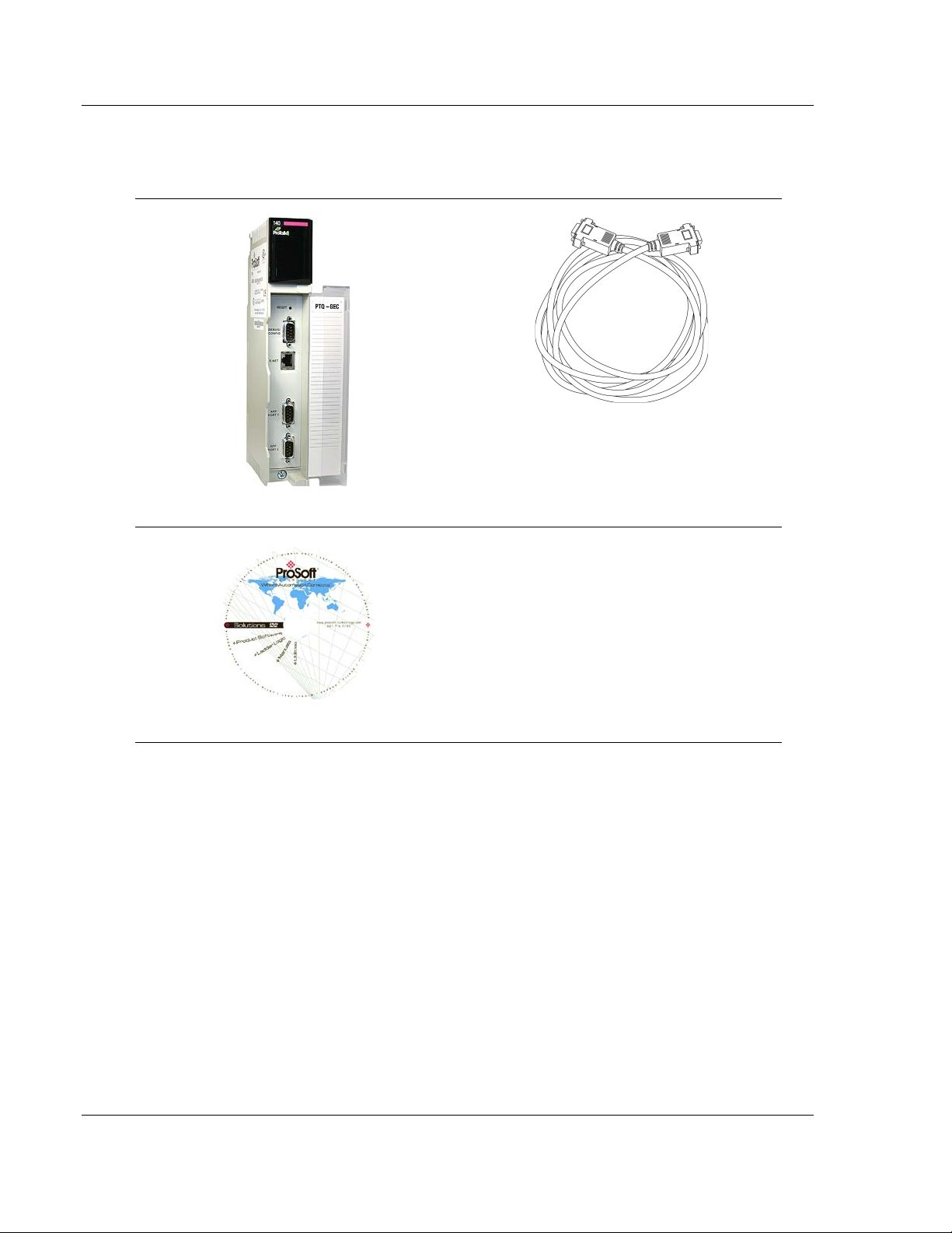
ProTalk Module
Null Modem Serial Cable
ProSoft Solutions DVD
12TUser Manual 46TIEC 60870-5-104 Server for Quantum
1.1 Hardware and Software Requirements
1.1.1 Package Contents
1.1.2 Quantum Hardware
This guide assumes that you are familiar with t he installation and setup of the
Quantum hardware. The following should be installed, configured, and powered
up before proceeding:
Quantum Processor
Quantum rack
Quantum power supply
Quantum Modbus Plus Network Option Module (NOM) (optional)
Quantum to PC programming hardware
NOM Ethernet or Serial connection to PC
Page 12 of 201 ProSoft Technology, Inc.
March 4, 2013
Page 13

48TPTQ-104S Rev 1 ♦ 47TQuantum Platform Start Here
46TIEC 60870-5-104 Server for Quantum 12TUser Manual
1.1.3 PC and Software
Windows-based PC with at least one COM port
Quantum programming software installed on machine
or
Concept™ PLC Programming Software version 2.6
or
ProWORX PLC Programming Software
or
Unity™ Pro PLC Programming Software
Note: ProTalk modules are compatible with common Quantum programming applications,
including Concept and Unity Pro. For all other programming applications, please contact technical
support.
1.2 Install ProSoft Configuration Builder Software
This manual is meant for use of PTQ-104S Rev1. PCB version 2.2.0 and older
must be used for Rev1. Older versions of PCB can be found at
http://www.prosoft-technology.com/pcb
ProSoft Configuration Builder (PCB) software is used to configure the module.
To install ProSoft Configuration Builder from the ProSoft Web Site
1 Open your web browser and navigate to http://www.prosoft-
technology.com/pcb
2 Click the D
ProSoft Configuration Builder.
3 Choose S
4 Save the file to your Windows Desktop, so that you can find it easily when
you have finished downloading.
5 When the download is complete, locate and open the file, and then follow the
instructions on your screen to install the program.
If you do not have access to the Internet, you can install ProSoft Configuration
Builder from the ProSoft Solutions DVD, included in the package with your
module.
To install ProSoft Configuration Builder from the Product DVD
1 Insert the ProSoft Solutions Product DVD into the DVD drive of your PC. Wait
for the startup screen to appear.
2 On the startup screen, click P
Windows Explorer file tree window.
3 Click to open the U
and files you will need to set up and configure your module.
OWNLOAD HERE link to download the appropriate version of
AVE or SAVE FILE when prompted.
RODUCT DOCUMENTATION. This action opens a
TILITIES folder. This folder contains all of the applications
ProSoft Technology, Inc. Page 13 of 201
March 4, 2013
Page 14
Start Here 48TPTQ-104S Rev 1 ♦ 47TQuantum Platform
12TUser Manual 46TIEC 60870-5-104 Server for Quantum
4 Double-click the SETUP CONFIGURATION TOOL folder, double-click the
PCB_*.
EXE file and follow the instructions on your screen to install the
software on your PC. The information represented by the "*" character in the
file name is the PCB version number and, therefore, subject to change as
new versions of PCB are released.
Note: Many of the configuration and maintenance procedures use files and other utilities on the
DVD. You may wish to copy the files from the Utilities folder on the DVD to a convenient location
on your hard drive.
1.3 Setting Up the ProTalk Module
After you complete the following procedures, the ProTalk module will actively be
transferring data bi-directionally with the processor.
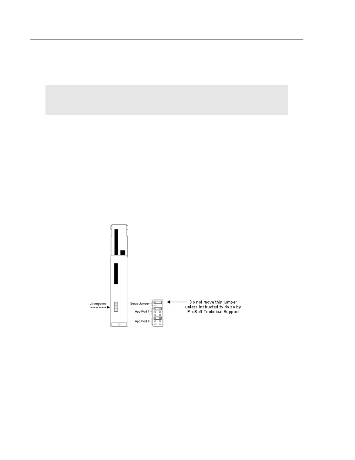
1.3.1 Install the ProTalk Module in the Quantum Rack
Verify Jumper Settings
ProTalk modules are configured for RS-232 serial communications by default. To
use RS-422 or RS-485, you must change the jumpers.
The jumpers are located on the back of the module as shown in the following
illustration:
Page 14 of 201 ProSoft Technology, Inc.
March 4, 2013
Page 15

48TPTQ-104S Rev 1 ♦ 47TQuantum Platform Start Here
46TIEC 60870-5-104 Server for Quantum 12TUser Manual
Install the ProTalk Module in the Quantum Rack
1 Place the Module in the Quantum Rack. The ProTalk module must be placed
in the same rack as the processor.
2 Tilt the module at a 45° angle and align the pegs at the top of the module with
slots on the backplane.
3 Push the module into place until it seats firmly in the backplane.
Caution: The PTQ module is hot-swappable, meaning that you can install and remove it while the
rack is powered up. You should not assume that this is the case for all types of modules unless the
user manual for the product explicitly states that the module is hot-swappable. Failure to observe
this precaution could result in damage to the module and any equipment connected to it.
ProSoft Technology, Inc. Page 15 of 201
March 4, 2013
Page 16
Start Here 48TPTQ-104S Rev 1 ♦ 47TQuantum Platform
12TUser Manual 46TIEC 60870-5-104 Server for Quantum
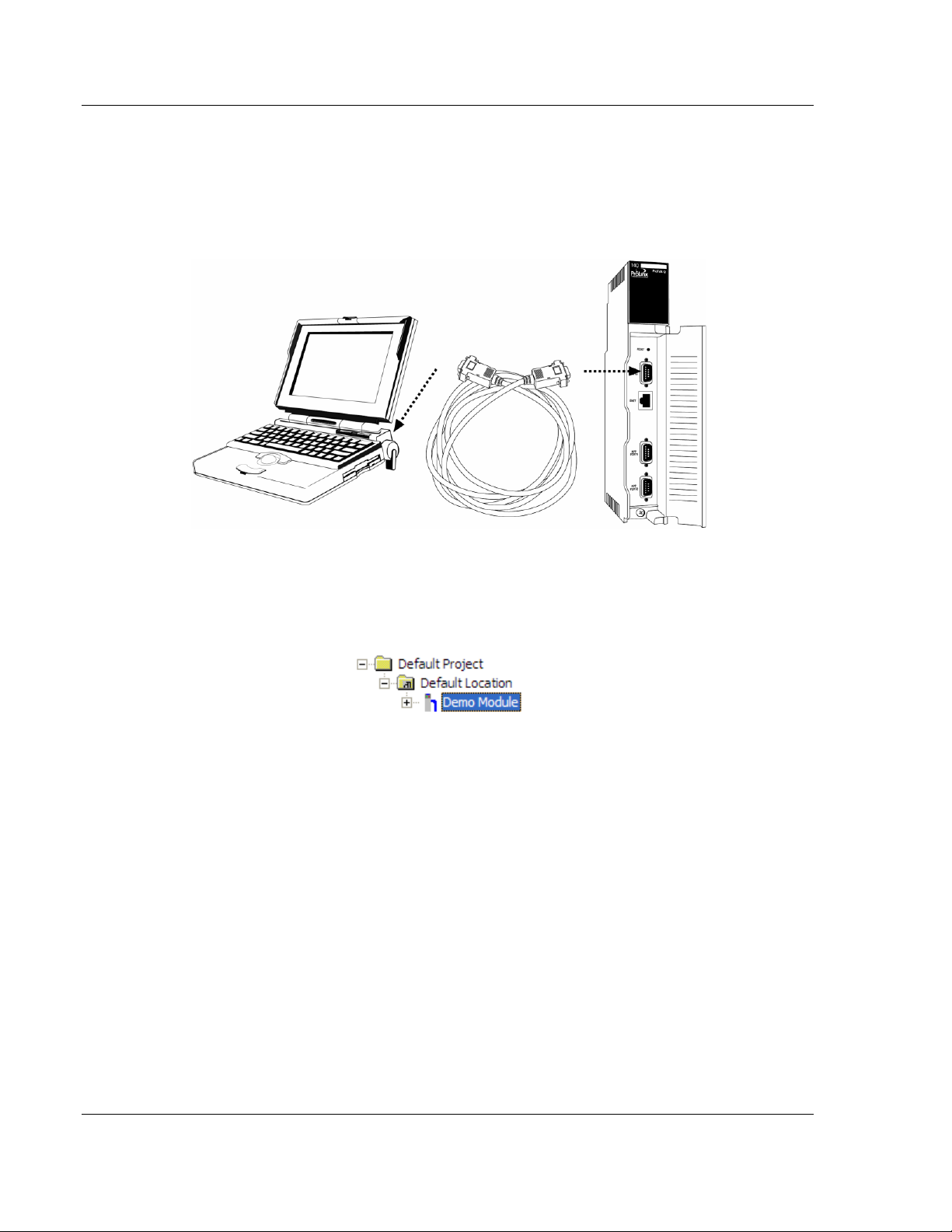
1.3.2 Connect the PC to the ProTalk Configuration/Debug Port
Make sure you have exited the Quantum programming software before
performing these steps. This action will avoid serial port conflict.
Using the supplied Null Modem cable, connect your PC to the
Configuration/Debug port on the ProTalk module as shown
To connect to the module’s Configuration/Debug serial port:
1 Start PCB, and then select the module to test. Click the right mouse button to
open a shortcut menu.
Page 16 of 201 ProSoft Technology, Inc.
March 4, 2013
Page 17
48TPTQ-104S Rev 1 ♦ 47TQuantum Platform Start Here
46TIEC 60870-5-104 Server for Quantum 12TUser Manual
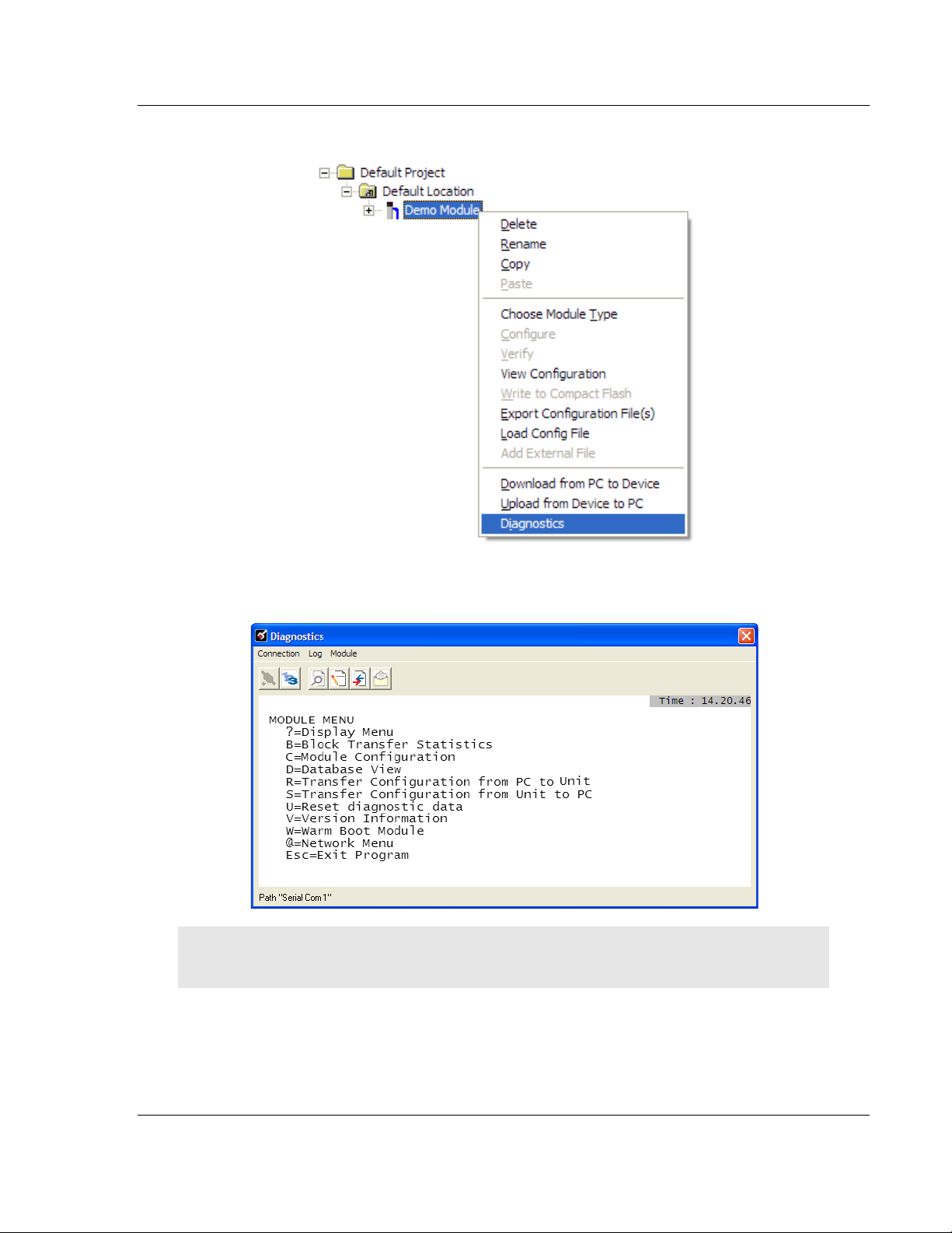
2 On the shortcut menu, choose DIAGNOSTICS.
This action opens the D
3 Press [?]
to open the Main Menu.
IAGNOSTICS dialog box.
Important: The illustrations of configuration/debug menus in this section are intended as a general
guide, and may not exactly match the configuration/debug menus in your own module.
ProSoft Technology, Inc. Page 17 of 201
March 4, 2013
Page 18
Start Here 48TPTQ-104S Rev 1 ♦ 47TQuantum Platform
12TUser Manual 46TIEC 60870-5-104 Server for Quantum
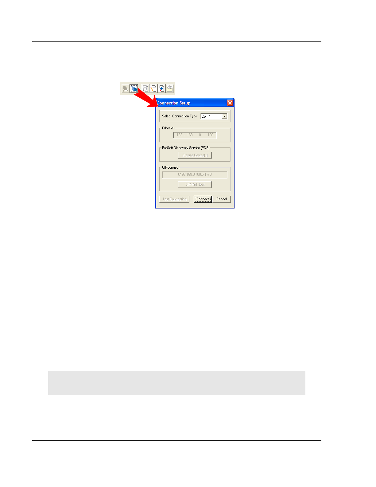
If there is no response from the module, follow these steps:
1 Click to configure the connection. On the Connection Setup dialog box, select
a valid com port or other connection type supported by the module.
2 Verify that the null modem cable is connected properly between your
computer’s serial port and the module. A regular serial cable will not work.
3 On computers with more than one serial port, verify that your communication
program is connected to the same port that is connected to the module.
4 If you are still not able to establish a connection, contact ProSoft Technology
for assistance.
1.3.3 Ethernet Configuration
Use this procedure to configure the Ethernet settings for your module. You must
assign an IP address, subnet mask and module address. After you complete this
step and download the configuration to the module, you can connect to the
module with an Ethernet cable.
1 Determine the network settings for your module, with the help of your network
administrator if necessary. You will need the following information:
o IP address (fixed IP required) _____ . _____ . _____ . _____
o Subnet mask _____ . _____ . _____ . _____
o Gateway address _____ . _____ . _____ . _____
Note: The module Address is optional, and is not required for networks that do not use a default
module.
Page 18 of 201 ProSoft Technology, Inc.
March 4, 2013
Page 19
48TPTQ-104S Rev 1 ♦ 47TQuantum Platform Start Here
46TIEC 60870-5-104 Server for Quantum 12TUser Manual
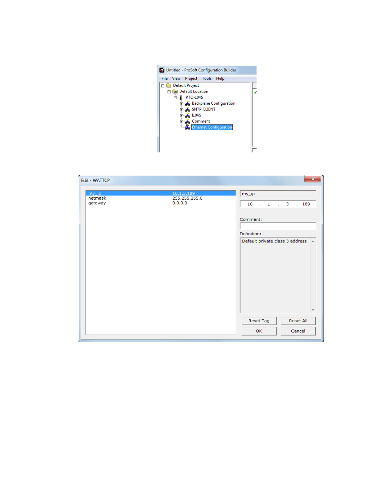
2 Double-click the ETHERNET CONFIGURATION icon.
3 This action opens the E
DIT dialog box.
4 Edit the values for my_ip, netmask (subnet mask) and gateway (default
gateway).
5 When finished editing, clic k OK
to save the changes and return to the ProSoft
Configuration Builder window.
ProSoft Technology, Inc. Page 19 of 201
March 4, 2013
Page 20

Start Here 48TPTQ-104S Rev 1 ♦ 47TQuantum Platform
12TUser Manual 46TIEC 60870-5-104 Server for Quantum
Page 20 of 201 ProSoft Technology, Inc.
March 4, 2013
Page 21

48TPTQ-104S Rev 1 ♦ 47TQuantum Platform Configuring the Processor with Unity Pro
46TIEC 60870-5-104 Server for Quantum 12TUser Manual
2 Configuring the Processor with Unity Pro
In This Chapter
Create a New Project ............................................................................ 22
Add the PTQ Module to the Project ....................................................... 24
Build the Project .................................................................................... 25
Connect Your PC to the Processor ....................................................... 26
Download the Project to the Processor ................................................. 28
The following steps are designed to ensure that the processor (Quantum or
Unity) is able to transfer data successfully with the PTQ module. As par t of this
procedure, you will use Unity Pro to create a project, add the PTQ module to the
project, set up data memory for the project, and then download the project to the
processor.
ProSoft Technology, Inc. Page 21 of 201
March 4, 2013
Page 22
Configuring the Processor with Unity Pro 48TPTQ-104S Rev 1 ♦ 47TQuantum Platform
12TUser Manual 46TIEC 60870-5-104 Server for Quantum
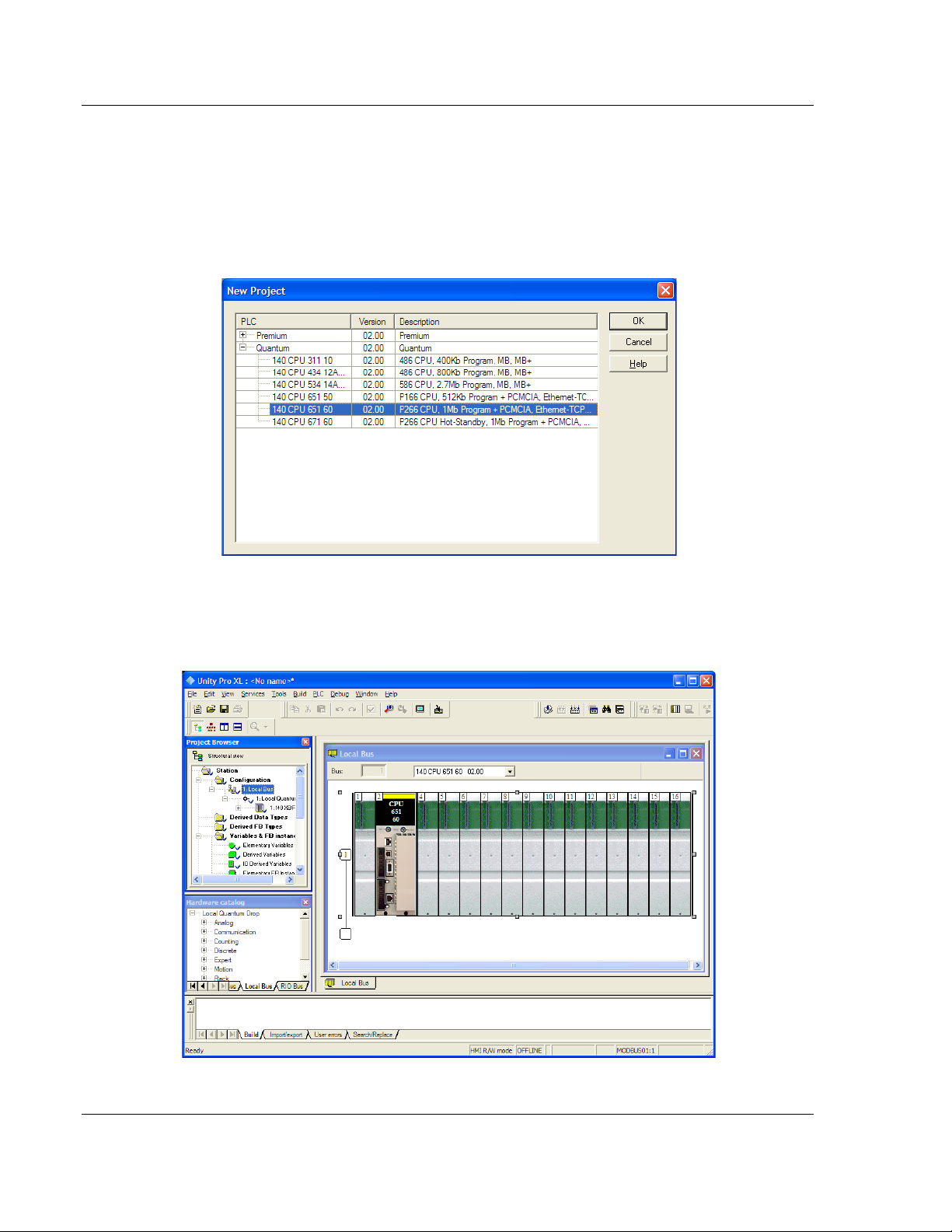
2.1 Create a New Project
The first step is to open Unity Pro and create a new project.
1 In the New Project dialog box, choose the CPU type. In the following
illustration, the CPU is 140 CPU 651 60. Choose the processor type that
matches your own hardware configuration, if it differs from the example. Click
OK
to continue.
2 Next, add a power supply to the project. In the Pro ject Browser, expand the
Configuration
folder, and then double-click the 1:LOCALBUS icon. This action
opens a graphical window showing the arrangement of devices in your
Quantum rack.
Page 22 of 201 ProSoft Technology, Inc.
March 4, 2013
Page 23
48TPTQ-104S Rev 1 ♦ 47TQuantum Platform Configuring the Processor with Unity Pro
46TIEC 60870-5-104 Server for Quantum 12TUser Manual
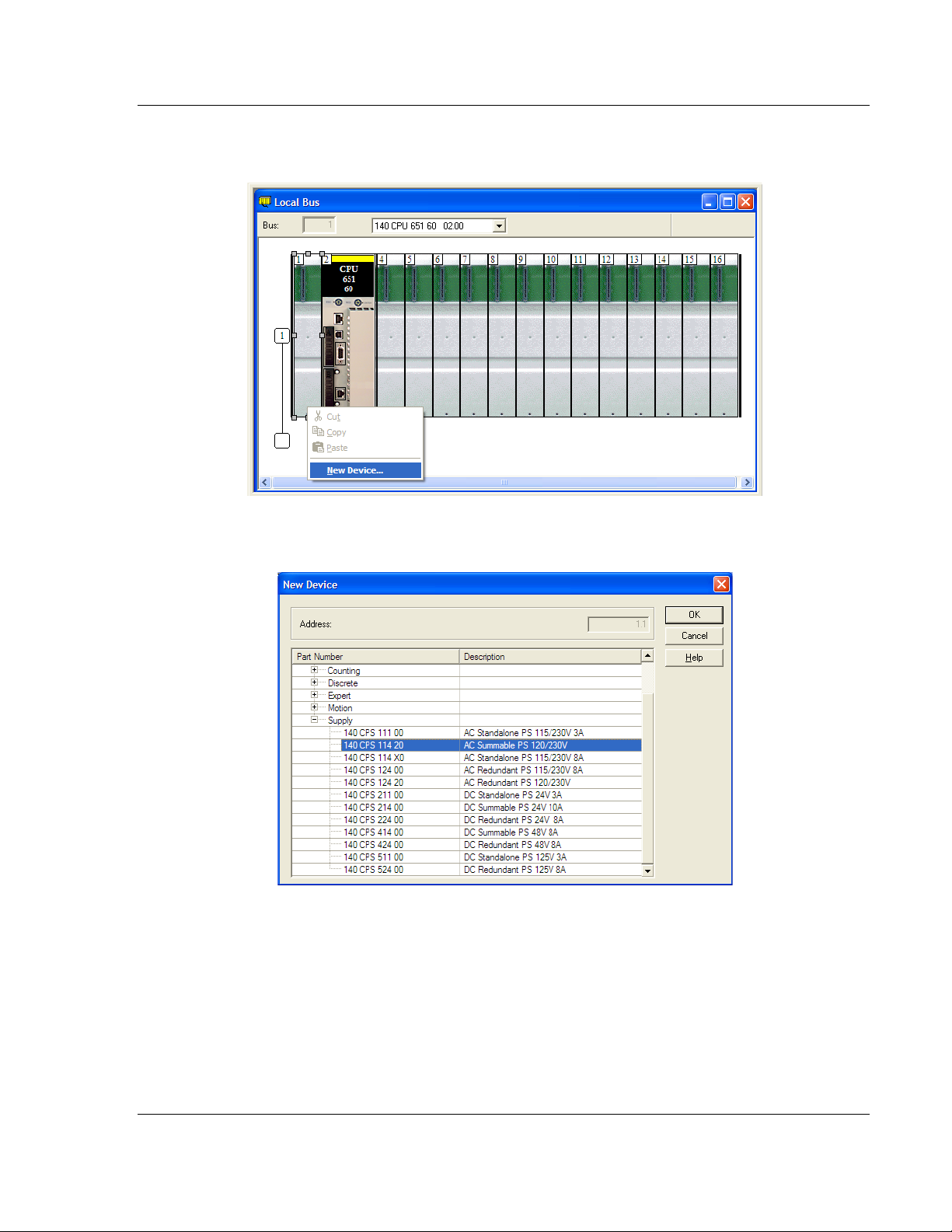
3 Select the rack position for the power supply, and then click the right mouse
button to open a shortcut menu. On the shortcut menu, choose N
EW DEVICE.
4 Expand the Supply folder, and then select your power supply from the list.
Click OK
to continue.
5 Repeat these steps to add any additional devices to your Quantum Rack.
ProSoft Technology, Inc. Page 23 of 201
March 4, 2013
Page 24
Configuring the Processor with Unity Pro 48TPTQ-104S Rev 1 ♦ 47TQuantum Platform
12TUser Manual 46TIEC 60870-5-104 Server for Quantum
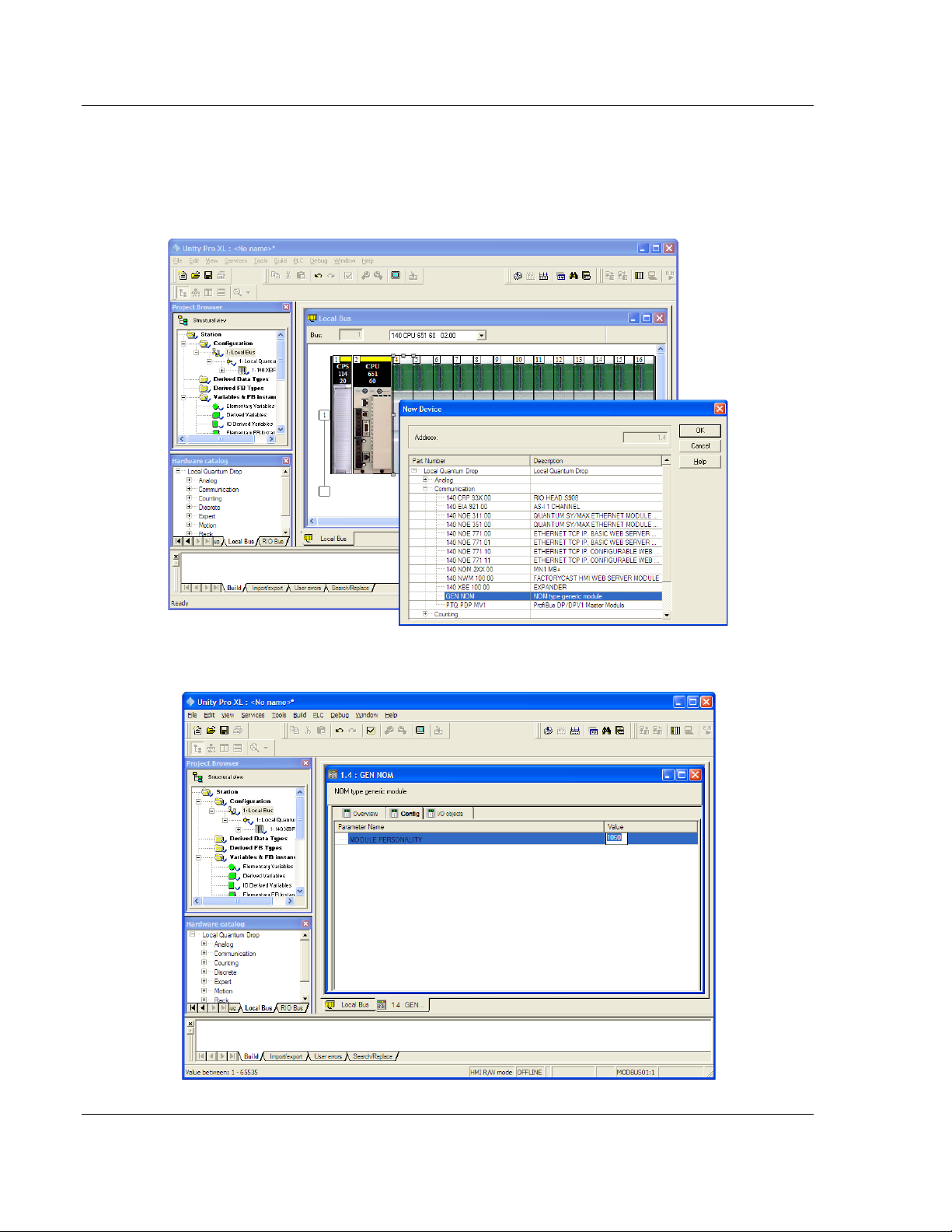
2.2 Add the PTQ Module to the Project
1 Expand the Communication tree, and select GEN NOM. This module type
provides extended communication capabilities for the Quantum system, and
allows communication between the PLC and the PTQ module without
requiring additional programming.
2 Next, enter the module personality value. The correct value for ProTalk
modules is 1060 decimal (0424 hex).
Page 24 of 201 ProSoft Technology, Inc.
March 4, 2013
Page 25
48TPTQ-104S Rev 1 ♦ 47TQuantum Platform Configuring the Processor with Unity Pro
46TIEC 60870-5-104 Server for Quantum 12TUser Manual
3 Before you can save the project in Unity Pro, you must validate the
modifications. Open the E
DIT menu, and then choose VALIDATE. If no errors
are reported, you can save the project.
4 S
AVE the project.
2.3 Build the Project
Whenever you update the configuration of your PTQ module or the processor,
you must import the changed configuration from the module, and then build
(compile) the project before downloading it to the processor.
Note: The following steps show you how to build the project in Unity Pro. This is not intended to
provide detailed information on using Unity Pro, or debugging your programs. Refer to the
documentation for your processor and for Unity Pro for specialized information.
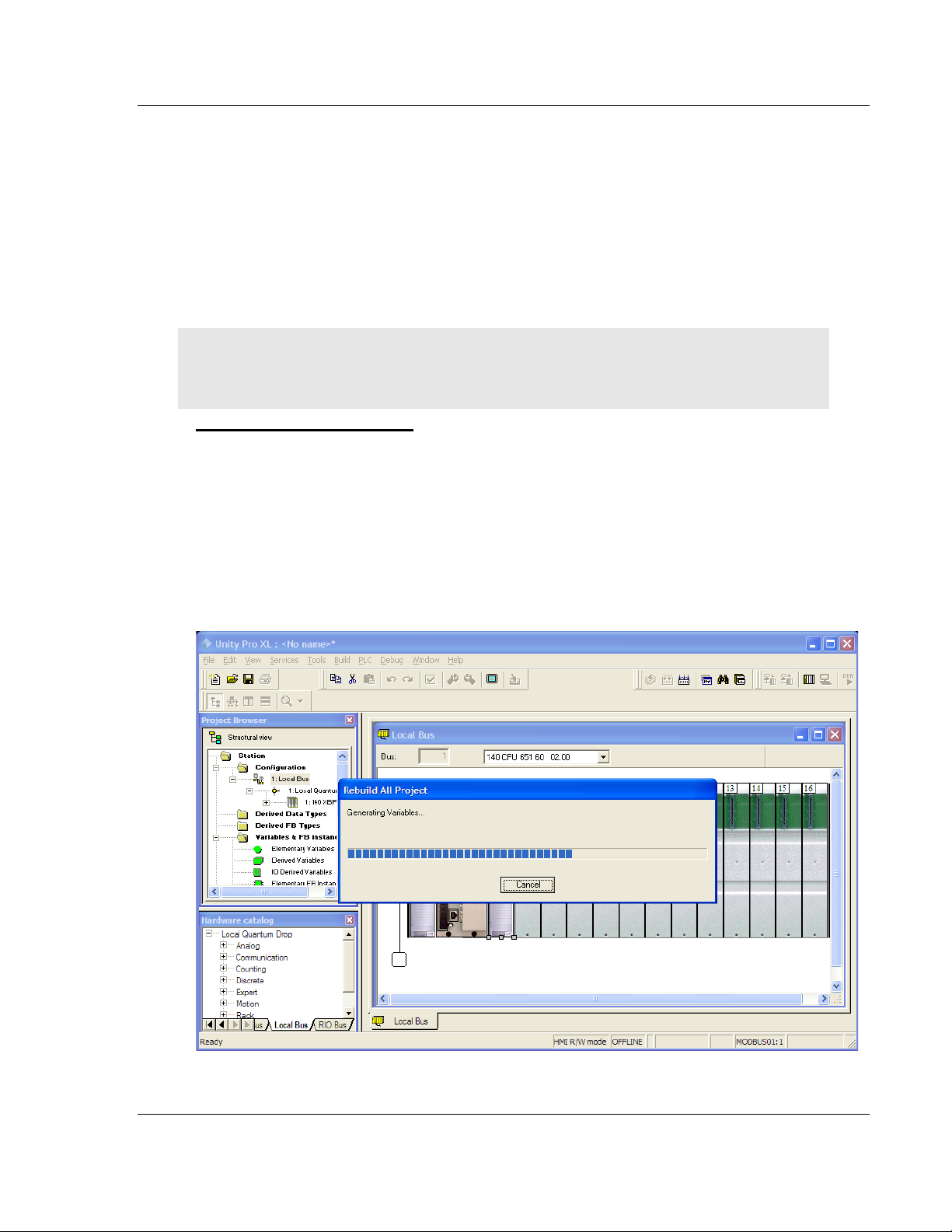
To build (compile) the project
1 Review the elements of the project in the Project Browser.
2 When you are satisfied that you are ready to download the project, open the
B
UILD menu, and then choose REBUILD ALL PROJECT. This action builds
(compiles) the project into a form that the processor can use to execute the
instructions in the project file. This task may take several minutes, depending
on the complexity of the project and the resources available on your PC.
3 As the project is built, Unity Pro reports its process in a Progress
with details appearing in a pane at the bottom of the window. The following
illustration shows the build process under way.
dialog box,
ProSoft Technology, Inc. Page 25 of 201
March 4, 2013
Page 26
Configuring the Processor with Unity Pro 48TPTQ-104S Rev 1 ♦ 47TQuantum Platform
12TUser Manual 46TIEC 60870-5-104 Server for Quantum
After the build process is completed successfully, the next step is to download
the compiled project to the processor.
2.4 Connect Your P C to the Processor
The next step is to connect to the processor so that you can download the project
file. The processor uses this project file to communicate over the backplane to
modules identified in the project file.
Note: If you have never connected from the PC to your processor before, you must verify that the
necessary port drivers are installed and available to Unity Pro.
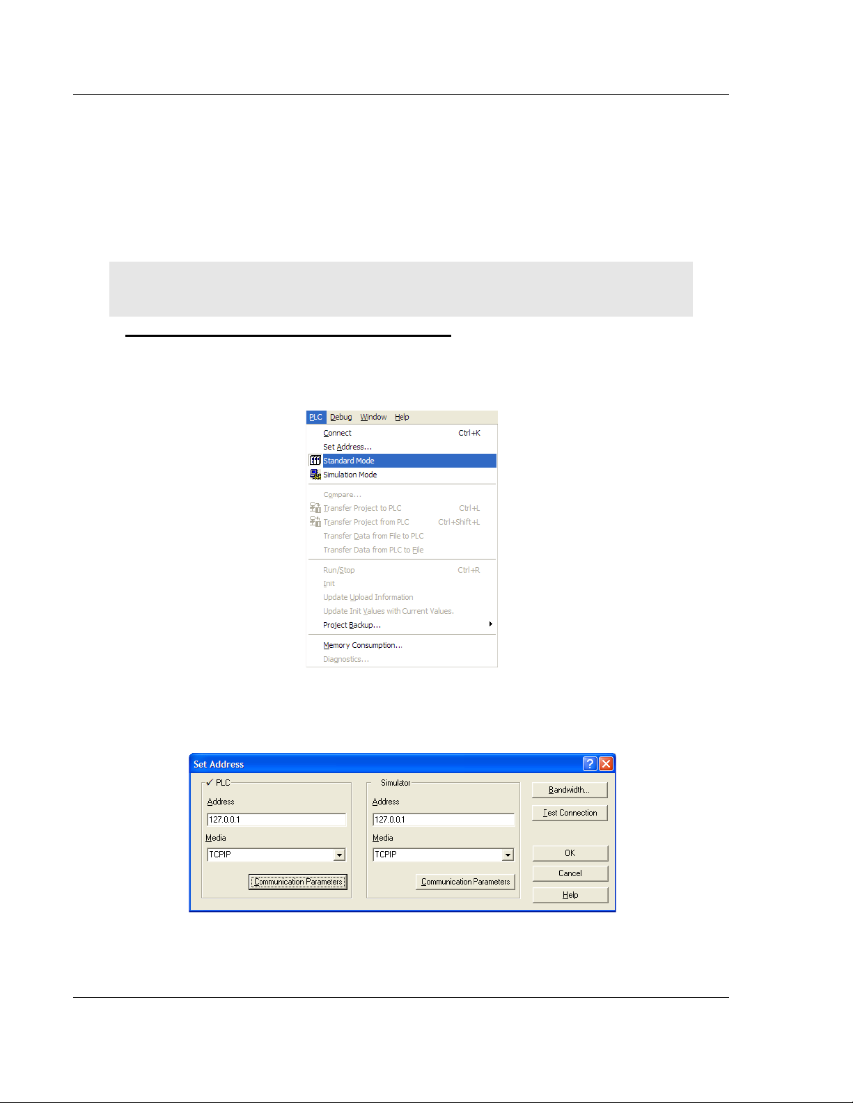
To verify address and driver settings in Unity Pro
1 Open the PLC menu, and choose STANDARD MODE. This action turns off the
PLC Simulator, and allows you to communicate directly with the Quantum or
Unity hardware.
2 Open the PLC
Address dialog box. Open the M
menu, and choose SET ADDRESS... This action opens the Set
EDIA dropdown list and choose the
connection type to use (TCPIP or USB).
Page 26 of 201 ProSoft Technology, Inc.
March 4, 2013
Page 27
48TPTQ-104S Rev 1 ♦ 47TQuantum Platform Configuring the Processor with Unity Pro
46TIEC 60870-5-104 Server for Quantum 12TUser Manual
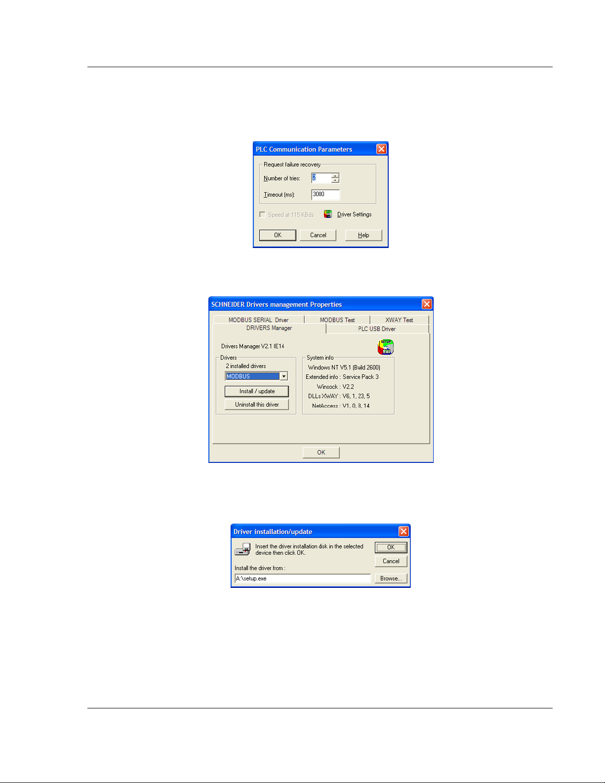
3 If the MEDIA dropdown list does not contain the connection method you wish
to use, click the C
OMMUNICATION PARAMETERS button in the PLC area of the
dialog box. This action opens the PLC Communication Parameters dialog
box.
4 Click the D
RIVER SETTINGS button to open the SCHNEIDER Drivers
management Properties dialog box.
5 Click the I
NSTALL/UPDATE button to specify the location of the Setup.exe file
containing the drivers to use. You will need your Unity Pro installation disks
for this step.
6 Click the B
ROWSE button to locate the Setup.exe file to execute, and then
execute the setup program. After the installation, restart your PC if you are
prompted to do so. Refer to your Schneider Electric documentation for more
information on installing drivers for Unity Pro.
ProSoft Technology, Inc. Page 27 of 201
March 4, 2013
Page 28
Configuring the Processor with Unity Pro 48TPTQ-104S Rev 1 ♦ 47TQuantum Platform
12TUser Manual 46TIEC 60870-5-104 Server for Quantum
2.4.1 Connecting to the Processor with TCP/IP
The next step is to download (copy) the project file to the processor. The
following steps demonstrate how to use an Ethernet cable connected from the
Processor to your PC through an Ethernet hub or switch. Other connection
methods may also be available, depending on the hardware configuration of your
processor, and the communication drivers installed in Unity Pro.
1 If you have not already done so, connect your PC and the processor to an
Ethernet hub.
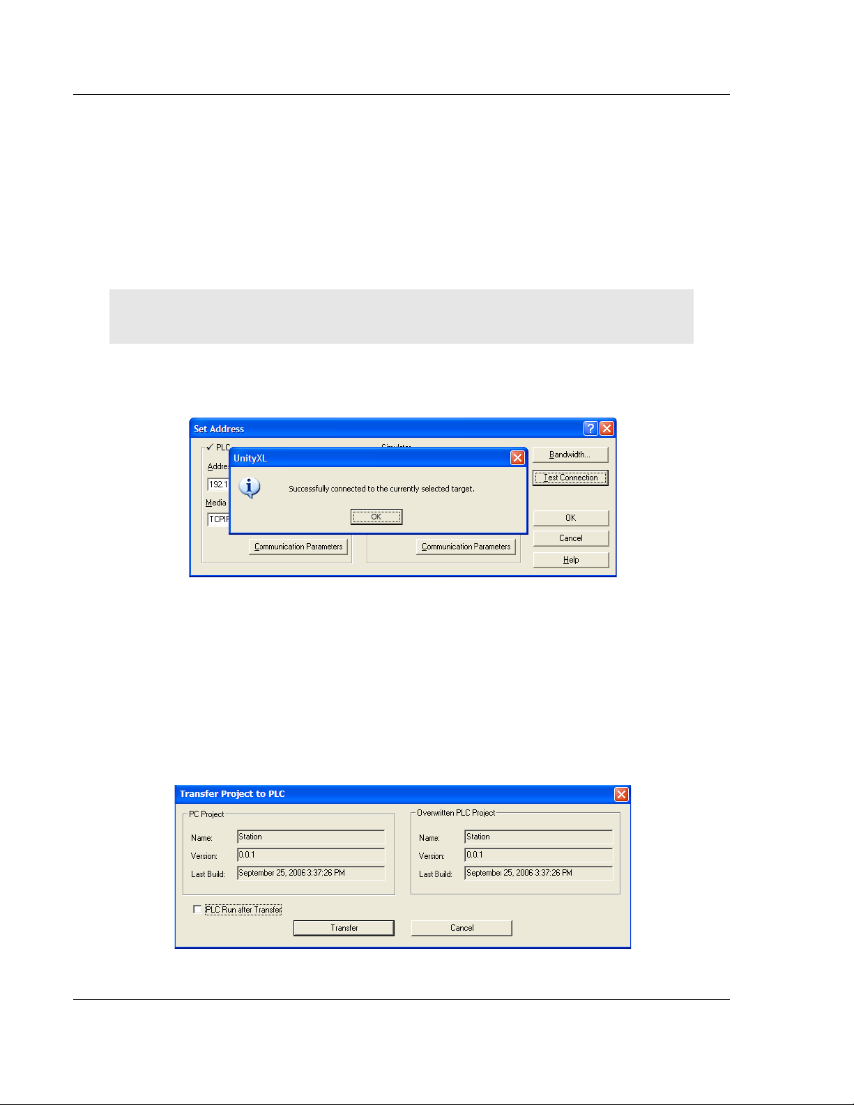
2 Open the PLC
Important: Notice that the Set Address dialog box is divided into two areas. Enter the address
and media type in the PLC area of the dialog box, not the SIMULATOR area.
3 Enter the IP address in the address field. In the MEDIA dropdown list, choose
TCPIP.
4 Click the
menu, and then choose SET ADDRESS.
TEST CONNECTION button to verify that your settings are correct.
2.5 Download the Project to the Processor
1 Open the PLC menu and then choose CONNECT. This action opens a
connection between the Unity Pro software and the processor, using the
address and media type settings you configured in the previous step.
2 On the PLC
the
TRANSFER PROJECT TO PLC dialog box. If you would like the PLC to go to
"Run" mode immediately after the transfer is complete, select (check) the
PLC
RUN AFTER TRANSFER check box.
menu, choose TRANSFER PROJECT TO PLC. This action opens
Page 28 of 201 ProSoft Technology, Inc.
March 4, 2013
Page 29

48TPTQ-104S Rev 1 ♦ 47TQuantum Platform Configuring the Processor with Unity Pro
46TIEC 60870-5-104 Server for Quantum 12TUser Manual
3 Click the TRANSFER button to download the project to the processor. As the
project is transferred, Unity Pro reports its process in a P
ROGRESS dialog box,
with details appearing in a pane at the bottom of the window.
When the transfer is complete, place the processor in Run mode.
ProSoft Technology, Inc. Page 29 of 201
March 4, 2013
Page 30

Configuring the Processor with Unity Pro 48TPTQ-104S Rev 1 ♦ 47TQuantum Platform
12TUser Manual 46TIEC 60870-5-104 Server for Quantum
Page 30 of 201 ProSoft Technology, Inc.
March 4, 2013
Page 31

48TPTQ-104S Rev 1 ♦ 47TQuantum Platform Configuring the Processor with Concept
46TIEC 60870-5-104 Server for Quantum 12TUser Manual
3 Configuring the Processor with Concept
In This Chapter
Information for Concept Version 2.6 Users............................................ 32
Creating a New Project.......................................................................... 33
Adding the PTQ Module to the Project .................................................. 36
Setting the Time of Day ......................................................................... 39
Saving the Project ................................................................................. 40
Downloading the Project to the Processor............................................. 42
The following steps are designed to ensure the processor is able to transfer data
successfully with the PTQ module. As part of this procedure, Concept
configuration software from Schneider Electric will be used to create a project,
add the PTQ module to the project, set up data memory for the project, and
download the project to the processor.
Important Note: Concept software does not report whether the PTQ module is present in the rack
Therefore, it is not able to report the health status of the module when the module is online with the
Quantum processor. Please consider this when monitoring the status of the PTQ module.
ProSoft Technology, Inc. Page 31 of 201
March 4, 2013
Page 32

Configuring the Processor with Concept 48TPTQ-104S Rev 1 ♦ 47TQuantum Platform
12TUser Manual 46TIEC 60870-5-104 Server for Quantum
3.1 Information for Concept Version 2.6 Users
This guide uses Concept PLC Programming Software version 2.6 to configure
the Quantum PLC. The ProSoft Solutions DVD includes MDC module
configuration files that help document the PTQ installation. Although not required,
these files should be installed before proceeding to the next section.
3.1.1 Installing MDC Configuration Files
1 From a PC with Concept 2.6 installed, choose START / PROGRAMS / CONCEPT
/ MODCONNECT TOOL.
This action opens the Concept Module Installation dialog box.
2 Choose F
ILE / OPEN INSTALLATION FILE.
This action opens the Open Installation File dialog box:
3 If a Quantum processor is being used, the MDC files will be needed. In the
Open Installation File dialog box, navigate to the MDC Files directory on the
ProSoft Solutions DVD.
Page 32 of 201 ProSoft Technology, Inc.
March 4, 2013
Page 33

48TPTQ-104S Rev 1 ♦ 47TQuantum Platform Configuring the Processor with Concept
46TIEC 60870-5-104 Server for Quantum 12TUser Manual
4 Choose the MDC file and help file for the version of Concept:
o Concept 2.6 users: select PTQ_2_60.mdc and PTQMDC.hlp
o Concept 2.5 users: select PTQ_2_50.mdc and PTQMDC.hlp.
Select the files that go with the Concept version being used, and then click
OK. This action opens the Add New Modules dialog box.
5 Click the
process. Click Y
ADD ALL button. A series of message boxes may appear during this
ES or OK for each message that appears.
6 When the process is complete, open the F
the changes.
3.2 Creating a New Project
ILE menu and choose EXIT to save
This phase of the setup procedure must be performed on a computer that has
the Concept configuration software installed.
1 From the computer, choose S
TART / PROGRAMS / CONCEPT V2.6 XL.EN /
CONCEPT. This action opens the Concept window.
ProSoft Technology, Inc. Page 33 of 201
March 4, 2013
Page 34

Configuring the Processor with Concept 48TPTQ-104S Rev 1 ♦ 47TQuantum Platform
12TUser Manual 46TIEC 60870-5-104 Server for Quantum
2 Open the File menu, and then choose NEW PROJECT. This action opens the
PLC Configuration dialog box.
3 In the list of options on the left side of this dialog box, double-click the PLC
SELECTION folder. This action opens the PLC Selection dialog box.
Page 34 of 201 ProSoft Technology, Inc.
March 4, 2013
Page 35

48TPTQ-104S Rev 1 ♦ 47TQuantum Platform Configuring the Processor with Concept
46TIEC 60870-5-104 Server for Quantum 12TUser Manual
4 In the CPU/Executive pane, use the scroll bar to locate and select the PLC to
configure.
5 Click OK.
This action opens the PLC Configuration dialog box, populated with
the correct values that were selected for the PLC.
6 Make a note of the holding registers for the module. This information will be
needed when modifying the application. The Holding Registers are displayed
in the PLC Memory Partition pane of the
PLC Configuration dialog box.
ProSoft Technology, Inc. Page 35 of 201
March 4, 2013
Page 36

Configuring the Processor with Concept 48TPTQ-104S Rev 1 ♦ 47TQuantum Platform
12TUser Manual 46TIEC 60870-5-104 Server for Quantum
3.3 Adding the PTQ Module to the Project
1 In the list of options on the left side of the PLC Configuration dialog box,
double-click
I/O MAP. This action opens the I/O Map dialog box.
2 Click the E
DIT button to open the Local Quantum Drop dialog box. This dialog
box is where rack and slot locations are identified.
Page 36 of 201 ProSoft Technology, Inc.
March 4, 2013
Page 37

48TPTQ-104S Rev 1 ♦ 47TQuantum Platform Configuring the Processor with Concept
46TIEC 60870-5-104 Server for Quantum 12TUser Manual
3 Click the MODULE button next to the rack/slot position where the ProTalk
module will be installed. This action opens the I/O Module Selection dialog
box.
4 In the Modules pane, use the scroll bar to locate and select the ProTalk
module, and then click OK.
This action copies the description of the ProTalk
module next to the assigned rack and slot number of the Local Quantum
Drop dialog box.
5 Repeat steps 3 through 5 for each ProTalk module that is being installed.
When finished installing the ProTalk modules, click OK
Click Y
ES to confirm the settings.
to save the settings.
ProSoft Technology, Inc. Page 37 of 201
March 4, 2013
Page 38

Configuring the Processor with Concept 48TPTQ-104S Rev 1 ♦ 47TQuantum Platform
12TUser Manual 46TIEC 60870-5-104 Server for Quantum
Tip: Select a module, and then click the Help on Module button for help pages.
Page 38 of 201 ProSoft Technology, Inc.
March 4, 2013
Page 39

48TPTQ-104S Rev 1 ♦ 47TQuantum Platform Configuring the Processor with Concept
46TIEC 60870-5-104 Server for Quantum 12TUser Manual
3.4 Setting the Time of Day
1 In the list of options on the left side of the PLC Configuration dialog box,
double-click S
PECIALS.
2 This action opens the S
PECIALS dialog box.
ProSoft Technology, Inc. Page 39 of 201
March 4, 2013
Page 40

Configuring the Processor with Concept 48TPTQ-104S Rev 1 ♦ 47TQuantum Platform
12TUser Manual 46TIEC 60870-5-104 Server for Quantum
3 Select (check) the Time of Day box, and then enter the value 00001 as
shown in the following illustration. This value sets the first time of day register
to 400001.
4 Click OK
to save your settings and close the Specials dialog box.
3.5 Saving the Project
1 In the PLC Configuration dialog box, choose FILE / SAVE PROJECT AS.
Page 40 of 201 ProSoft Technology, Inc.
March 4, 2013
Page 41

48TPTQ-104S Rev 1 ♦ 47TQuantum Platform Configuring the Processor with Concept
46TIEC 60870-5-104 Server for Quantum 12TUser Manual
2 This action opens the Save Project As dialog box.
3 Name the project, and then click OK
to save the project to a file.
ProSoft Technology, Inc. Page 41 of 201
March 4, 2013
Page 42

Configuring the Processor with Concept 48TPTQ-104S Rev 1 ♦ 47TQuantum Platform
12TUser Manual 46TIEC 60870-5-104 Server for Quantum
3.6 Downloading the Project to the Processor
Next, download (copy) the project file to the Quantum Processor.
1 Use the null modem cable to connect the PC’s serial port to the Quantum
processor, as shown in the following illustration.
Note: A Modbus Plus Network Option Module (NOM) can be used in place of the serial port if
necessary.
2 Open the PLC menu, and then choose CONNECT.
3 In the PLC Configuration dialog box, open the O
choose C
ONNECT. This action opens the Connect to PLC dialog box.
NLINE menu, and then
4 Leave the default settings as shown and click OK.
Page 42 of 201 ProSoft Technology, Inc.
March 4, 2013
Page 43

48TPTQ-104S Rev 1 ♦ 47TQuantum Platform Configuring the Processor with Concept
46TIEC 60870-5-104 Server for Quantum 12TUser Manual
Note: Click OK to dismiss any message boxes that appear during the connection process.
5 In the PLC Configuration window, open the ONLINE menu, and then choose
D
OWNLOAD. This action opens the Download Controller dialog box.
6 Click A
that the controller is running, click Y
LL, and then click DOWNLOAD. If a message box appears indicating
ES to shut down the controller. The
Download Controller dialog box displays the status of the download as shown
in the following illustration.
7 When the download is complete, a prompt to restart the controller will display.
Click Y
ES to restart the controller.
ProSoft Technology, Inc. Page 43 of 201
March 4, 2013
Page 44

48TPTQ-104S Rev 1 ♦ 47TQuantum Platform
12TUser Manual 46TIEC 60870-5-104 Server for Quantum
Page 44 of 201 ProSoft Technology, Inc.
March 4, 2013
Page 45

48TPTQ-104S Rev 1 ♦ 47TQuantum Platform Configuring the Processor with ProWORX
46TIEC 60870-5-104 Server for Quantum 12TUser Manual
4 Configuring the Processor with ProWORX
When you use ProWORX 32 software to configure the processor, use the
example SAF file provided on the ProTalk Solutions DVD.
Important Note: ProWORX software does not report whether the PTQ module is present in the
rack, and therefore is not able to report the health status of the module when the module is online
with the Quantum processor. Please consider this when monitoring the status of the PTQ module.
1 Run the SCHNEIDER_ALLIANCES.EXE application that is installed with the
ProWORX 32 software:
2 Click on I
MPORT…
ProSoft Technology, Inc. Page 45 of 201
March 4, 2013
Page 46

Configuring the Processor with ProWORX 48TPTQ-104S Rev 1 ♦ 47TQuantum Platform
12TUser Manual 46TIEC 60870-5-104 Server for Quantum
3 Select the .SAF File that is located on the DVD shipped with the PTQ
module.
4 After clicking O
the M
ODULE as PTQ:
PEN, select the I/O SERIES as QUANTUM SERIES. Also, select
5 Close the Schneider Alliances application.
Page 46 of 201 ProSoft Technology, Inc.
March 4, 2013
Page 47

48TPTQ-104S Rev 1 ♦ 47TQuantum Platform Configuring the Processor with ProWORX
46TIEC 60870-5-104 Server for Quantum 12TUser Manual
6 Run the ProWORX 32 software. W hether a new or existing project is used,
click on the Traffic Cop section to display the rack to be edited.
7 Highlight Slot x by clicking on the slot in the rack display. In this case, the
PTQ module will be placed in slot 3.
Below the rack display is the Properties drop-down box for slot 3, select PTQ.
8 Save the project. It is now ready to be downloaded to the Processor.
ProSoft Technology, Inc. Page 47 of 201
March 4, 2013
Page 48

Configuring the Processor with ProWORX 48TPTQ-104S Rev 1 ♦ 47TQuantum Platform
12TUser Manual 46TIEC 60870-5-104 Server for Quantum
Page 48 of 201 ProSoft Technology, Inc.
March 4, 2013
Page 49

48TPTQ-104S Rev 1 ♦ 47TQuantum Platform Module Configuration
46TIEC 60870-5-104 Server for Quantum 12TUser Manual
5 Module Configuration
In This Chapter
Using ProSoft Configuration Builder ...................................................... 50
[Backplane Configuration] ..................................................................... 54
Backplane Data Exchange .................................................................... 55
Modify the [Backplane Data Exchange] Section .................................... 63
[SNTP CLIENT] ..................................................................................... 74
[IEC-870-5-104] ..................................................................................... 76
IEC 60870-5-104 Server section ........................................................... 87
[IEC-870-5-104 Database]..................................................................... 88
[IEC-870-5-104 IP Addresses] ............................................................... 92
[M_SP_NA_1 104] ................................................................................. 92
[M_DP_NA_1 104] ................................................................................ 93
[M_ST_NA_1 104] ................................................................................. 93
[M_BO_NA_1 104] ................................................................................ 93
[M_ME_NA_1 104] ................................................................................ 94
[M_ME_NB_1 104] ................................................................................ 94
[M_ME_NC_1 104] ................................................................................ 94
[M_IT_NA_1 104] .................................................................................. 95
[C_SC_NA_1 104] ................................................................................. 95
[C_DC_NA_1 104] ................................................................................. 96
[C_RC_NA_1 104] ................................................................................. 96
[C_BO_NA_1 104] ................................................................................. 96
[C_SE_NA_1 104]
[C_SE_NB_1 104] ................................................................................. 97
[C_SE_NC_1 104] ................................................................................. 98
Group Codes ......................................................................................... 98
CommonNet Data Map .......................................................................... 99
Download the Project to the Module .................................................... 103
To Create Optional Comment Entries.................................................. 102
To Print a Configuration File ................................................................ 102
................................................................................. 97
ProSoft Technology, Inc. Page 49 of 201
March 4, 2013
Page 50

Module Configuration 48TPTQ-104S Rev 1 ♦ 47TQuantum Platform
12TUser Manual 46TIEC 60870-5-104 Server for Quantum
5.1 Using ProSoft Configuration Builder
ProSoft Configuration Builder (PCB) provides a quick and easy way to manage
module configuration files customized to meet your application needs. PCB is not
only a powerful solution for new configuration files, but also allows you to import
information from previously installed (known working) configurations to new
projects.
5.1.1 Setting Up the Project
To begin, start ProSoft Configuration Builder. If you have used other W indows
configuration tools before, you will find the screen layout familiar. ProSoft
Configuration Builder’s window consists of a tree view on the left, an information
pane and a configuration pane on the right side of the window.
When you first start ProSoft Configuration Builder, the tree view consists of
folders for Default Project and Default Location, with a Default Module in the
Default Location folder. The following illustration shows the ProSoft Configuration
Builder window with a new project.
Page 50 of 201 ProSoft Technology, Inc.
March 4, 2013
Page 51

48TPTQ-104S Rev 1 ♦ 47TQuantum Platform Module Configuration
46TIEC 60870-5-104 Server for Quantum 12TUser Manual
Your first task is to add the PTQ-104S module to the project.
1 Use the mouse to select D
EFAULT MODULE in the tree view, and then click the
right mouse button to open a shortcut menu.
2 On the shortcut menu, choose C
C
HOOSE MODULE TYPE dialog box.
HOOSE MODULE TYPE. This action opens the
ProSoft Technology, Inc. Page 51 of 201
March 4, 2013
Page 52

Module Configuration 48TPTQ-104S Rev 1 ♦ 47TQuantum Platform
12TUser Manual 46TIEC 60870-5-104 Server for Quantum
3 In the PRODUCT LINE FILTER area of the dialog box, select PTQ. In the SELECT
MODULE TYPE dropdown list, select PTQ-104S, and then click OK to save
your settings and return to the P
ROSOFT CONFIGURATION BUILDER window.
The next task is to set the module parameters.
Page 52 of 201 ProSoft Technology, Inc.
March 4, 2013
Page 53

48TPTQ-104S Rev 1 ♦ 47TQuantum Platform Module Configuration
46TIEC 60870-5-104 Server for Quantum 12TUser Manual
5.1.2 Set Module Parameters
Notice that the contents of the information pane and the configuration pane
changed when you added the PTQ-104S module to the project.
At this time, you may wish to rename the "Default Project" and "Default Location"
folders in the tree view.
To rename an object
1 Select the object, and then click the right mouse button to open a shortcut
menu. From the shortcut menu, choose R
ENAME.
2 Type the name to assign to the object.
3 Click away from the object to save the new name.
To configure module parameters
1 Click on the plus sign next to the icon to expand module information.
2 Double-click the icon to open the Edit
dialog box.
3 To edit a parameter, select the parameter in the left pane and make your
changes in the right pane.
4 Click OK
to save your changes.
To print a configuration file
1 Select the module icon, and then click the right mouse button to open a
shortcut menu.
ProSoft Technology, Inc. Page 53 of 201
March 4, 2013
Page 54

Module Configuration 48TPTQ-104S Rev 1 ♦ 47TQuantum Platform
12TUser Manual 46TIEC 60870-5-104 Server for Quantum
2 On the shortcut menu, choose VIEW CONFIGURATION. This action opens the
View Configuration window.
3 On the View Configuration window, open the F
ILE menu, and choose PRINT.
This action opens the Print dialog box.
4 On the Print dialog box, choose the printer to use from the dropdown list,
select printing options, and then click OK.
5.2 [Backplane Configuration]
This section provides the module with a unique name, identifies the method of
failure for the communications for the module if the processor is not in run, and
describes how to initialize the module upon startup.
5.2.1 Module Name
0 to 80 characters
This parameter assigns a name to the module that can be viewed using the
configuration/debug port. Use this parameter to identify the module and the
configuration file.
5.2.2 Failure Flag Count
0 through 65535
This parameter specifies the number of successive transfer errors that must
occur before halting communication on the application port(s). If the parameter is
set to 0, the application port(s) will continue to operate under all conditions. If the
value is set larger than 0 (1 to 65535), communications will cease if the specified
number of failures occur.
Page 54 of 201 ProSoft Technology, Inc.
March 4, 2013
Page 55

48TPTQ-104S Rev 1 ♦ 47TQuantum Platform Module Configuration
Application Memory Address
0
=
0
10
=
10
20
=
20
30
=
30
40
=
40
50
=
50
…
206
=
206
207
=
207
…
=
…
312
=
312
46TIEC 60870-5-104 Server for Quantum 12TUser Manual
5.2.3 Error Offset
0 to 3980, or -1 to disable
This parameter specifies the database location where to write status data.
5.2.4 Initialize Output Data
Yes or No
This parameter determines if the output data for the module should be initialized
with values from the processor. If the value is set to No (0), the output data will
be initialized to 0. If the value is set to Yes (1), the data will be initialized with
data from the processor. Use of this option requires associated ladder logic to
pass the data from the processor to the module.
5.3 Backplane Data Exchang e
Before modifying the [Backplane Data Exchange] section of the configuration file,
you must understand some important concepts. The following topics describe
these concepts.
If you have used the parameters defined in the [Module] section, you have
created the following memory map. We will use this map to explain how data
transfer works between the processor and the ProTalk module.
PTQ Memory Address
…
A thorough understanding of the information contained in this section is required
for successful implementation of the module in a user application.
5.3.1 Data Transfer
The module uses a concept referred to as "Command Functions". The command
functions reside in the [Backplane Data Exchange] section of the configuration
file. This method of data transfer is probably different from other methods you
might have used, but does offer some unique advantages:
The amount of ladder logic required will be substantially reduced; in fact in
many applications no ladder logic will be required.
The module may be placed in any position in the chassis containing the PLC
and will operate with no modifications.
ProSoft Technology, Inc. Page 55 of 201
March 4, 2013
Page 56

Module Configuration 48TPTQ-104S Rev 1 ♦ 47TQuantum Platform
12TUser Manual 46TIEC 60870-5-104 Server for Quantum
Refer to PTQ-104S Protocol Implementation (page 131) to see how this method
works. It contains a very simple example of reading and writing to the PLC and
should help to illustrate the concept. If you have the equipment available to use
this would be a great way to get a feel for the command functions used to
transfer data. The following discussion is generic in nature and is meant outline
the steps required to create your first application.
5.3.2 Defining Data to be Sent to the PTQ Database
You might be asked to provide access to 207 words of information for other
devices on the network. This information resides in the PLC at addresses 400001
to 400207 and you must make this the first 207 words of the database inside the
module. This would require the use of "Command Function 1".
Because the total amount of data exceeds the maximum length of any single
command function, you will need two entries in the [Backplane Data Exchange]
section of your configuration file. This might look like the following:
Page 56 of 201 ProSoft Technology, Inc.
March 4, 2013
Page 57

48TPTQ-104S Rev 1 ♦ 47TQuantum Platform Module Configuration
Field
Value
Meaning
1
The type of operation to perform
PTQ Address
0
The destination address within the PTQ
4
The range of registers to read from the Quantum
1
The starting address of the data within the Quantum
Word Count
100
The number of registers to transfer
Field
Value
Meaning
1
The type of operation to perform
PTQ Address
100
The destination address within the PTQ
4
The range of registers to read from the Quantum
104
The starting address of the data within the Quantum
Word Count
107
The number of registers to transfer
PTQ Memory Address
0
40010
First Command
9
19
29
39
40060
59
69
79
89
99
100
40111
Second Command
110
…
199
206
…
46TIEC 60870-5-104 Server for Quantum 12TUser Manual
The first command states:
Command Type
Point Type
Quantum Address
1 = Read data from the Quantum into the PTQ
4 = 4:x style register
This would be Point Type + offset
Example: 40000 + 1 = 40001
The second command states:
Command Type
Point Type
Quantum Address
1 = Read data from the Quantum into the PTQ
4 = 4:x style register
This would be Point Type + Quantum Address
Example: 40000 + 104 = 40104
The following diagram shows the result of this example.
Quantum Memory Address
40001
40020
40030
40040
…
40070
40080
40090
40100
40104
40200
40207
…
ProSoft Technology, Inc. Page 57 of 201
March 4, 2013
Page 58

Module Configuration 48TPTQ-104S Rev 1 ♦ 47TQuantum Platform
Field
Value
Meaning
2
The type of operation to perform
PTQ Address
207
The destination address within the PTQ
4
The range of registers to read from the Quantum
208
The starting address of the data within the Quantum
Word Count
105
The number of registers to transfer
12TUser Manual 46TIEC 60870-5-104 Server for Quantum
5.3.3 Defining Data to be Retrieved from the PTQ Database.
Your application may need to retrieve 105 words of data from other devices on
the network. These devices have either sent you the data if you are a server, or
you have obtained it for your use if you happen to be a master in your
application. Assuming that the data resides in registers 207 to 312 within the
PTQ modules memory and you wish to place this information in addresses
400208 to 400313 within the Quantum you could use Command Function 2 to
transfer the information.
Because the total amount of data does not exceed 130 words in length, a single
command can be used to transfer the data. This additional entry will be added to
our [Backplane Data Exchange] section and it would look like the third command
below:
The th i rd command states:
Command Type
Point Type
Quantum Address
Page 58 of 201 ProSoft Technology, Inc.
March 4, 2013
2 = Write data from the PTQ to the Quantum
4 = 4:x style register
This would be Point Type + Quantum Address
Example: 40000 + 207 = 40207
Page 59

48TPTQ-104S Rev 1 ♦ 47TQuantum Platform Module Configuration
PTQ Memory Address
0
40010
First Command
9
19
29
39
40060
59
69
79
89
99
100
40111
Second Command
110
…
199
206
…
207
40210
Third Command
209
…
…
40310
309
312
46TIEC 60870-5-104 Server for Quantum 12TUser Manual
The following diagram shows the result of this example:
Quantum Memory Address
40001
40020
40030
40040
…
40070
40080
40090
40100
40104
40200
40207
…
40208
40313
5.3.4 Defining Special Functions
Your application may perform what might be considered a special function such
as setting/retrieving the time and date or issuing an event to the module. This
section will discuss the requirements for the command and offer an example of
how it might be used.
ProSoft Technology, Inc. Page 59 of 201
March 4, 2013
Page 60

Module Configuration 48TPTQ-104S Rev 1 ♦ 47TQuantum Platform
Field
Value
Meaning
3
The type of operation to perform
PTQ Address
0
This is ALWAYS 0 and will not overwrite your database.
4
The range of registers to read from the Quantum
500
The starting address of the data within the Quantum
Word Count
64
This is ALWAYS 64 words in length.
12TUser Manual 46TIEC 60870-5-104 Server for Quantum
Assuming that you have chosen registers 400500 to 400563 as the target for
your Command Function 3 you could enter the following command into the
Backplane Data Exchange section of your configuration file.
The fourth command states:
Cmd Type
Point Type
Quantum Address
3 = Read/Write special function to the Quantum.
4 = 4:x style register
This would be Point Type + Quantum Address
Example: 40000 + 500 = 40500
Note: This command requires two PLC scans to complete. When you issue a Function 3 we will
examine the "Quantum Address" registers, process the information, clear the registers and post the
status if applicable.
Page 60 of 201 ProSoft Technology, Inc.
March 4, 2013
Page 61

48TPTQ-104S Rev 1 ♦ 47TQuantum Platform Module Configuration
PTQ Memory Address
0
40010
First Command
9
19
29
39
40060
59
69
79
89
99
100
40111
Second Command
110
…
199
206
…
207
40210
Third Command
209
…
…
40310
309
312
N/A
40510
Fourth Command
N/A
40520
1st Scan
N/A
40530
N/A
40540
2nd Scan
N/A
40550
N/A
N/A
N/A
46TIEC 60870-5-104 Server for Quantum 12TUser Manual
The following diagram shows this example:
Quantum Memory Address
40001
40020
40030
40040
…
40070
40080
40090
40100
40104
40200
40207
…
40208
40313
40500
40560
40563
ProSoft Technology, Inc. Page 61 of 201
March 4, 2013
Page 62

Module Configuration 48TPTQ-104S Rev 1 ♦ 47TQuantum Platform
12TUser Manual 46TIEC 60870-5-104 Server for Quantum
5.3.5 Implementing Ladder to Support Special Functions.
The previous discussions about Command Function 1 and Command Function 2
have not required that you implement any form of logic within the PLC, however if
you are required to use the Command Function 3, you must implement some
form of control logic. The following section uses structured text language to
illustrate how a typical function might be implemented.
Example: Rebooting the module
(*
MyTrigger is an alias for register 401000
MyFunction3 is an alias for register 400500
MyData1-MyData63 are aliases for 400501-400563
The premise for this logic is:
IF MyTrigger = SOMEVALUE THEN
Fill the buffer;
set MyFunction3 to the appropriate value;
Clear MyTrigger with a 0;
END_IF;
*)
IF MyTrigger = 9999 THEN
MyFunction3 := MyTrigger;
MyTrigger := 0;
END_IF;
Example: Setting / Retrieving the time of day
(*
Block ID 9971 - Set Modules Time using the PLC’s Time
Assumption:
The MyYear, MyMonth and so on... values for time and date represent
aliases for your time source.
MyTrigger is an alias for register 401000.
*)
IF MyTrigger = 9971 THEN;
MyData1 := MyYear;
MyData2 := MyMonth;
MyData3 := MyDay;
MyData4 := MyHour;
MyData5 := MyMinute;
MyData6 := MySeconds;
MyData7 := MyMillisec;
MyFunction3 := 9971;
MyTrigger := 0;
END_IF;
(*
Block ID 9970 - Set PLC’s time using the modules time
Assumption:
The MyYear, MyMonth and so on... values for time and date are
representative of your aliases for your time source.
Page 62 of 201 ProSoft Technology, Inc.
March 4, 2013
Page 63

48TPTQ-104S Rev 1 ♦ 47TQuantum Platform Module Configuration
46TIEC 60870-5-104 Server for Quantum 12TUser Manual
MyTrigger is an alias for register 400010.
*)
IF MyTrigger = 9970 THEN;
MyFunction3 := MyTrigger;
IF MyFunction3 = 0 AND MyData1 = 9970 THEN;
MyYear := MyData2;
MyMonth := MyData3;
MyDay := MyData4;
MyHour := MyData5;
MyMinute := MyData6;
MySeconds := MyData7;
MyTrigger := 0;
END_IF;
END_IF;
The previous examples all utilize structured text for the process control logic but
follow the same basic program flow.
1 Copy the data related to the block function into registers 400501 to 400563
as required.
2 As your last step, copy the BLOCK ID number of the special function into
register 400500.
3 Clear your permissive condition.
The module will read the data in and either clear the registers in the array, or
return the requested data and clear the Block ID register (400500 in this
example).
5.4 Modify the [Backplane Data Exchange] Section
The previous sections provided an overview of what is required to modify the
[Backplane Data Exchange] section. With this information, you are now ready to
make the necessary modifications to the configuration file to work with your
application.
The following is an example of a typical [Backplane Data Exchange] section:
ProSoft Technology, Inc. Page 63 of 201
March 4, 2013
Page 64

Module Configuration 48TPTQ-104S Rev 1 ♦ 47TQuantum Platform
12TUser Manual 46TIEC 60870-5-104 Server for Quantum
This example shows an application that reads 207 words from the Quantum to
the module and writes 105 words from the module to the Quantum.
The [Backplane Data Exchange] section is a series of messages that instruct the
module how to transfer data to/from the Quantum. What is missing from the
message is the ability to schedule its execution. This ability is normally left to the
programmer in the PLC environment. However, in the PTQ module this is not
included so that the commands may run as fast as possible to maintain the
synchronization of the two databases. One command from the list will execute
during each I/O service interval at the end of the PLC ladder logic evaluation. So
as an example if your configuration contains 10 "Backplane Data Exchange"
commands it will require 10 PLC scans to process the entire list.
This section may contain up to 100 individual commands used in any
combination to transfer data to/from the Quantum. The following topics provide
information on the use of the commands as well as simple examples.
5.4.1 Set Up Command Function 1 (Read data from the Quantum)
This section provides information on how to read data from the Quantum into the
module.
Command Function 1 is designed to transfer data from the Quantum to the
module on a continuous basis. The command(s) required to transfer your
application data should be entered in the [BACKPLANE DATA EXCHANGE]
section of your configuration file as required.
This command takes the following parameters:
Command type: 1 (Read data from the Quantum)
PTQ Database Address: The destination for the data retrieved from the
Quantum.
Point Type: The type of register within the Quantum (0:x = 0, 1:x = 1 3:x = 3
or 4:x = 4)
Quantum Address: The source of the data within the Quantum. The address
is expressed without the use of the register range, for example 400001 would
be entered as 1 (400001 - 400000 = 1 or 40001 - 40000 = 1)
Word Count: The number of words to copy. The length of this copy may be
any length of 1 to 130 inclusive. If your application requires the movement of
additional data you may enter additional commands.
Page 64 of 201 ProSoft Technology, Inc.
March 4, 2013
Page 65

48TPTQ-104S Rev 1 ♦ 47TQuantum Platform Module Configuration
46TIEC 60870-5-104 Server for Quantum 12TUser Manual
Example 3:x or 4:x Register Transfer
The following example shows a typical command used to read 4:x data from the
Quantum. In this example, registers 400001 to 400099 from the Quantum will be
transferred to registers 0 to 99 within the module.
Example 0:x or 1:x Register Transfer
The transfer of Coils and Input bits require some forethought as the command
transfers words and not bits. This means that if you want to transfer bits 000005
to 000007 from the Quantum to word 21 in the module you would have to
transfer the word within the Quantum containing bits 000001 to 000016 to a
word within the modules memory.
Take care with the transfer of bits while planning the application so as to optimize
the usage of the available bits and to preserve the integrity of your information.
ProSoft Technology, Inc. Page 65 of 201
March 4, 2013
Page 66

Module Configuration 48TPTQ-104S Rev 1 ♦ 47TQuantum Platform
12TUser Manual 46TIEC 60870-5-104 Server for Quantum
The following example shows how this could be accomplished.
5.4.2 Set Up Command Function 2 (Write data to the Quantum)
This section provides information on how to write data from the module to the
Quantum.
Command Function 2 (two) is designed to transfer data from the module to the
Quantum on a continuous basis. The command(s) required to transfer your
application data should be entered in the [BACKPLANE DATA EXCHANGE]
section of your configuration file as required.
This command takes the following parameters:
Command type: 2 (Write data to the Quantum)
PTQ Database Address: The source of the data within the PTQ to be sent to
the Quantum.
Point Type: The type of register within the Quantum (0:x = 0, 1:x = 1 3:x = 3
or 4:x = 4)
Quantum Address: The destination register within the Quantum. The address
is expressed without the use of the register range, for example 400001 would
be entered as 1 (400001 - 400000 = 1 or 40001 - 40000 = 1)
Word Count: The number of words to copy. The length of this copy may be
any length of 1 to 130 inclusive. If your application requires the movement of
additional data you may enter additional commands.
Page 66 of 201 ProSoft Technology, Inc.
March 4, 2013
Page 67

48TPTQ-104S Rev 1 ♦ 47TQuantum Platform Module Configuration
46TIEC 60870-5-104 Server for Quantum 12TUser Manual
Example 3:x or 4:x Register Transfer
The following example shows a typical command used to write to the 4:x
registers within the Quantum. In this example, registers 207 to 312 from the PTQ
will be transferred to registers 400208 to 400313 within the Quantum.
Example 0:x or 1:x Register Transfer
The transfer of Coils and Inputs require some forethought as the command
transfers words and not bits. This means that if you wanted to transfer the word
containing the bits 805 to 806 from the module to the Quantum you would
transfer the entire 50
th
word of the modules memory into the destination register
in the Quantum. The following command transfer bits 800 to 815 (Word x Bits =
Bit Address or 50 * 16 = 800) from the modules memory to word 1 of the coils
(000001 to 000016) within the Quantum.
Take care with the transfer of bits while planning the application so as to optimize
the usage of the available bits and to preserve the integrity of your information.
ProSoft Technology, Inc. Page 67 of 201
March 4, 2013
Page 68

Module Configuration 48TPTQ-104S Rev 1 ♦ 47TQuantum Platform
12TUser Manual 46TIEC 60870-5-104 Server for Quantum
The following example shows how this could be accomplished.
5.4.3 Set Up Command Function 3 (Special Functions)
This section provides information on how to request the module to perform
special non-typical functions that may be required by an application.
Command Function 3 if required should be the first item entered in the
[BACKPLANE DATA EXCHANGE] section of your conf iguration file.
This may be used with all modules to implement the following functionality:
Force a reboot of the PTQ module (Special Function 9998 or 9999 available
on all products)
Set / Retrieve Time and Date (DNP and IEC only!)
Register events with the protocol (DNP and IEC only!)
Other modules may implement additional functionality, which will be described in
the Special Functions section of this manual.
This command takes the following parameters:
Command type: 3 (Control Block)
PTQ Database Address: This value is ALWAYS 0. Note: This will NOT
overwrite your application database in the PTQ but merely serves as an
additional flag to notify the module of the unique nature of the command.
Point Type: The type of register within the Quantum (0:x = 0, 1:x = 1 3:x = 3
or 4:x = 4)
Quantum Address: The source register within the Quantum. The address is
expressed without the use of the register range, for example 400001 would
be entered as 1 (400001 - 400000 = 1 or 40001 - 40000 = 1)
Word Count: This value is ALWAYS 64. Care should be taken to assure that
64 words of memory are available within the Quantum.
Page 68 of 201 ProSoft Technology, Inc.
March 4, 2013
Page 69

48TPTQ-104S Rev 1 ♦ 47TQuantum Platform Module Configuration
Word Offset in Block
Data Field(s)
Description
Block ID
This field contains the value of 9250 identifying the
1 to 247
Not Used
Not Used
46TIEC 60870-5-104 Server for Quantum 12TUser Manual
Example 3:x or 4:x Register Transfer
The following example shows a typical command used to retrieve a special
function command from the Quantum. In this example, registers 400500 to
400563 from the Quantum will be used to provide the information required by the
module.
The following section shows the functions that may be performed by using the
Command Function 3.
5.4.4 Read Status (9250)
Use block 9250 to request the module's status data. The module supports a
buffer queue of 99 events per data type. The application can verify the status of
the queue (free space in the queue) through the module's status data (Block
9250). When the queue is full, the module will delete the older event in the queue
if a new event is received.
There are two ways to request status data:
Read the data in the database, starting at word 4000. Refer to Error Status
Table (page 176) for detailed information.
Request the entire status block with a block 9250 block request.
The module responds to a valid block 9250 request with a block containing the
requested status data. The status data area for the module starts at address
4000 in the database.
The format of this block is shown in the following table.
Block Format for Write
0
block type to the module.
ProSoft Technology, Inc. Page 69 of 201
March 4, 2013
Page 70

Module Configuration 48TPTQ-104S Rev 1 ♦ 47TQuantum Platform
Word Offset in Block
Data Field(s)
Description
Done Flag
The word will be set to 0 when the command is
1
Block ID
This word will contain the value of 9250
Scan Count
This status value contains a counter incremented
Product Name
This two-word data area contains the text values
Revision
This two-word data area contains the text values
Op Sys #
This two-word data area contains the text values
Run Number
This two-word data area contains the text values
Number of block
This data area contains the total number of block
Number of block
This word contains the total number of block write
Number of blocks
This word contains the total number of write
Number of block
This word contains the total number of block
15
t0 Timeout
Number of t0 errors recognized by the module
16
t1 Timeout
Number of t1 errors recognized by the module
17
t2 Timeout
Number of t2 errors recognized by the module
18
t3 Timeout
Number of t3 errors recognized by the module
Receive Sequence
This word contains the current Receive Sequence
Bad Address
This word contains the number of messages
Bad Length
This word contains the number of messages
22
Rx Count
Number of messages sent
23
Tx Count
Number of messages received
Socket State
This word contains the current socket state as
Socket Open Count
This word contains the number of times the socket
12TUser Manual 46TIEC 60870-5-104 Server for Quantum
Block Format for Read
0
2
3 to 4
5 to 6
7 to 8
9 to 10
11
12
13
14
reads
writes
parsed
transfer errors
complete.
on each scan of the module's main loop.
representing the product name.
for the revision number.
for the operating system number.
for the run number.
read errors.
errors.
blocks successfully parsed.
transfer errors.
19
20
21
24
25
number (NR) sent by the module. This value is a
part of every message sent to the client unit.
received with a wrong Common ASDU Address
value
received by the host that does not contain a valid
length field
follows:
-1 = Open Socket
0 = Wait for Connection
1 = Transmit Message if Ready
2 = Receive Packet and process message
3 = Process multiple messages in packet
50 = Send TestFR ACT
51 = Wait for TestFR Con
60 = Send S-Format Message
1000 = Close Socke t
1001 = Wait for Socket to Close
listen function was executed
Page 70 of 201 ProSoft Technology, Inc.
March 4, 2013
Page 71

48TPTQ-104S Rev 1 ♦ 47TQuantum Platform Module Configuration
Word Offset in Block
Data Field(s)
Description
Socket Close Count
This word contains the number of times the an
Socket Connect
This word contains the number of times a
28
Event Buffer 0
Event data from MSP free events
29
Event Buffer 1
Event data from MDP free events
30
Event Buffer 2
Event data from MST free events
31
Event Buffer 3
Event data from MMA free events
32
Event Buffer 4
Event data from MMB free events
33
Reserved
Reserved
34
Event Buffer 6
Event data from MIT free events
Word Offset in Block
Data Field(s)
Description
Block ID
This field contains the value of 9958 identifying the
Event Count
Number of events present in the block. Valid Values: 1
3
Event #1
Event data to add to event me ssage queue.
18
Event #2
Event data to add to event message queue.
33
Event #3
Event data to add to event message queue.
48
Event #4
Event data to add to event message queue.
46TIEC 60870-5-104 Server for Quantum 12TUser Manual
26
27
Count
active close function was executed
connection was established between with the
remote host unit
5.4.5 Event Messages (9958)
Block 9958 is reserved to send event messages from the processor to the
module. Each block can send up to 10 events to the module. If a value of 9958 is
placed in the control register, event messages are sent from the processor to the
module. Refer to Events (page 161) for more information about time stamped
events.
The module supports a buffer queue of 99 events per data type. When the queue
is full, the module will delete the older event in the queue if a new event is
received.
This block should only be used to pass events with a predefined timestamp (the
module will also send time stamped events when database values change).
While using block 9958, disable the events for those specific points (refer to
Group Interrogation table) to avoid multiple event generation (caused by point
value update through the database).
The following table shows the block format for write.
Block Format for Write
1
2
ProSoft Technology, Inc. Page 71 of 201
March 4, 2013
block type to the module.
to 4.
Page 72

Module Configuration 48TPTQ-104S Rev 1 ♦ 47TQuantum Platform
Record
Data Field(s)
Description
DB Index
This is the index for the point in the module's
the third configured point, enter a value of 2 (first event
ASDU
This is the ASDU data type for the event message.
Qualifier
This is the qualifier code for the event message. This
3
Year
This field contains the four-digit year for this event.
Month
This field contains the month value for the event. Valid
Day
This field contains the day value for the event. Valid
Hour
This field contains the hour value for the event. Valid
Minute
This field contains the minute value for the event. Valid
Seconds and
This field contains the seconds and milliseconds value
Data
These words contain the data for the event. For single-
Word Offset in Block
Data Field(s)
Description
1
Block ID
This word will contain the value of 9958
12TUser Manual 46TIEC 60870-5-104 Server for Quantum
The structure of each event record in the block is shown in the following table.
Word Offset in Event
0
1
2
4
5
6
7
8
9 to 14
Milliseconds
database. This corresponds to the order of point
definition for the module data types. This is not the
point address for the event. For example, to refer to
is 0).
Valid entries for this field are as follows:
1=single-point
3=double-point
5=step
9=normalized
11=scaled
15=integrated total
parameter is only used for ASDU types 5, 9, 11 and
15. Refer to the IEC Protocol Specification for a full
listing of valid qualifier codes for one of these ASDU
types.
Values: 1 to 12
Values: 1 to 31
Values: 0 to 23
Values: 0 to 59
for the event. Valid Values: 0 to 59,999 (59 seconds
and 999 milliseconds).
and double-point, step, and measured value events,
the first word is used. For integrated total events, the
first two words are used.
Block Format for Read
5.4.6 Read Module's Time to Processor (9970)
If a value of 9970 is placed in the control register, the processor will read the
module's current time.
Page 72 of 201 ProSoft Technology, Inc.
March 4, 2013
Page 73

48TPTQ-104S Rev 1 ♦ 47TQuantum Platform Module Configuration
Word Offset in Block
Data Field(s)
Description
Block ID
This field contains the value of 9970 identifying the
Word Offset in Block
Data Field(s)
Description
1
Block ID
This word will contain the value of 9970.
Year
This field contains the four-digit year for the new time
Month
This field contains the month value for the new time.
Day
This field contains the day value for the new time.
Hour
This field contains the hour value for the new time.
Minute
This field contains the minute value for the new time.
Seconds
This field contains the second value for the new time.
Milliseconds
This field contains the millisecond value for the new
Word Offset in Block
Data Field(s)
Description
0
Write Block ID
This word will contain the value of 9971.
Year
This field contains the four-digit year for the new time
Month
This field contains the month value for the new time.
Day
This field contains the day value for the new time. Valid
Hour
This field contains the hour value for the new time. Valid
Minute
This field contains the minute value for the new time.
Seconds
This field contains the second value for the new time.
Milliseconds
This field contains the millisecond value for the new
46TIEC 60870-5-104 Server for Quantum 12TUser Manual
Block Format for Write
The following table shows the block format for write:
1
block type to the module.
Block Format for Read
The module responds to a valid 9970 request with a block containing the
requested date and time. The block format is shown in the following table.
2
3
4
5
6
7
8
value.
Valid Values: 1 to 12.
Valid Values: 1 to 31.
Valid Values: 0 to 23
Valid Values: 0 to 59.
Valid Values: 0 to 59.
time. Valid Values: 0 to 999.
5.4.7 Block 9971: Set Module Time
If a value of 9971 is placed in the control register, Module time is set using the
processor's time. The following table shows the block format for write.
Block 9971: Block Format for Write
1
value.
2
Valid Values: 1 to 12.
3
Values: 1 to 31.
4
Values: 0 to 23
5
Valid Values: 0 to 59.
6
Valid Values: 0 to 59.
7
time. Valid Values: 0 to 999.
ProSoft Technology, Inc. Page 73 of 201
March 4, 2013
Page 74

Module Configuration 48TPTQ-104S Rev 1 ♦ 47TQuantum Platform
Word Offset in Block
Data Field(s)
Description
1
Block ID
This word will contain the value of 9971
12TUser Manual 46TIEC 60870-5-104 Server for Quantum
Block Format for Read
5.4.8 Block 9998 or 9999: Reboot Module
If the processor places a value of 9998 in this register, the module will perform a
warm-boot operation. If the processor places a value of 9999 in this register, the
module will perform a cold-boot operation. In this application module, both of
these operations perform the same function. They exit the program and then
restart the program. Many of the program parameters set in the user
configuration must be set at program initialization and cannot be set while the
program is running. Therefore, both functions operate the same way.
5.5 [SNTP CLIENT]
The [SNTP CLIENT] section is used to specify the parameters for the Simple
Network Time Protocol (SNTP) Client provided with the protocol driver. This
client is read in order to keep the driver's internal clock set correctly. This version
of the driver supports SNTP Revision 3 and stratum between 1 and 14.
SNTP is used for time synchronization of produced and consumed commands.
When an exchange occurs the driver compares time stamps from the previous
exchange. When the new exchange time is less than the previous exchange, the
exchange is ignored. This can occur when the Ethernet packets are routed and
delayed. Time synchronization provides for data integrity.
# This section used to define the parameters required for the Simple Network
Time
# Protocol (SNTP) client.
[SNTP CLIENT]
#NTP SERVER IP ADDRESS : 132.163.4.102 #IP address for NIST, Boulder,
Colorado
NTP SERVER IP ADDRESS : 0.0.0.0 #IP Address for NTP Server
TIME ZONE : 8 #Number of hours from GMT (-11 to
+11)
USE DAYLIGHT SAVINGS TIME : No #Yes or No
DATABASE REGISTER : 3000 #database word location to store
time
#(-1=ignore). This register value should
#be an even number.
Page 74 of 201 ProSoft Technology, Inc.
March 4, 2013
Page 75

48TPTQ-104S Rev 1 ♦ 47TQuantum Platform Module Configuration
46TIEC 60870-5-104 Server for Quantum 12TUser Manual
The SNTP driver will compute a new clock value every 5 minutes using the
average value of 10 samples each collected over an approximate 6-second
period. This new value will be used to adjust the clock maintained by the SNTP
driver and used by the application. If a valid database register is specified, the
driver will place the time value into the module's database. The first two registers
will contain the number of seconds and the next two registers will contain the
number of microseconds since January 1, 1970.
A list of some of the common NTP servers can be obtained at http://www.ntp.org/
or, http://support.ntp.org/bin/view/Servers/WebHome
Other server lists can be found by searching the World Wide Web for "NTP
Servers".
5.5.1 NTP Server IP Address
Enter in dotted notation
This parameter sets the IP address of the NTP server to utilize for time
acquisition. Select an NTP server with the greatest accuracy that can be
accessed all the time from your network. Setting this IP address to 0.0.0.0
disables SNTP server requests.
5.5.2 Time Zone
-11 to 11
This parameter specifies the time zone offset to be used from the UTC time
zone. A value of zero uses UTC time. If the value entered is positive, the time
zone is west of the UTC time zone (that is, Eastern Standard Time is 5). I f the
value entered is negative, the time zone is east of the UTC time zone (that is,
Continental Europe is -1).
ProSoft Technology, Inc. Page 75 of 201
March 4, 2013
Page 76

Module Configuration 48TPTQ-104S Rev 1 ♦ 47TQuantum Platform
12TUser Manual 46TIEC 60870-5-104 Server for Quantum
5.5.3 Use Daylight Savings Time
Yes or No
This parameter specifies if daylight savings time will be used in the time
computation.
5.5.4 Database Register
-1 or 0 to 3992 as an even value
This parameter specifies if the NTP time computed by the driver is to be placed
into the module’s database. If a value of -1 is specified, the time will not be
placed into the database. If the value is between 0 and 3992, the time will be
placed in the database. The first 4 bytes will represent the seconds since
1/1/1970, and the second 4 bytes will represent the number of microseconds. An
even value should be used for the register value in order for the data to be stored
correctly.
5.6 [IEC-870-5-104]
This section provides information required to configure a server application with
the module. An item of concern is the maximum size of the total database.
Although it is possible to configure a database of considerable size, the
maximum Class 0 request may not exceed 2048 bytes in size.
Page 76 of 201 ProSoft Technology, Inc.
March 4, 2013
Page 77

48TPTQ-104S Rev 1 ♦ 47TQuantum Platform Module Configuration
46TIEC 60870-5-104 Server for Quantum 12TUser Manual
5.6.1 Use IP List
NO (0) or YES (1)
This parameter specifies if the IP address of the host connected to the system
will be validated. If the parameter is set to N
unit. If the parameter is set to Y
connect to the unit.
ES (1), only hosts in the IP list will be permitted to
O (0), any host may connect to the
5.6.2 Override StartDT
NO (0) or YES (1)
This parameter is used when testing the module with a simulator or with a Client
unit that does not meet the IEC 60870-5-104 specification. After the Client
connects to the module, it will send a STARTDT.ACT U-format message to the
module to permit the module to start sending data. If the Client does not support
this requirement, set the parameter to Y
Client sends the STARTDT.ACT message.
Note: This parameter must be set to NO (0) if you wish to use the redundant Clients feature.
ES (1). Set the parameter to NO (0) if the
5.6.3 Clear Queue on Close
NO (0) or YES (1)
Use this command to define whether the module will store the unacknowledged
buffers in the unit after the connection is closed. If the specification is to be
followed, set this parameter to N
O (0) and the packets will be resent after a
connection is made. If you want to flush the packets after the connection is
closed, set this parameter to Y
104 specification).
ES (1) (this is not according to the IEC 60870-5-
5.6.4 t0 Connection Timeout
1 to 1000, default value = 30
This is a timeout value, in seconds, to determine if a connection has been lost
with the remote Client. If no traffic from the remote client is received for the
period of time specified by this parameter, the currently open server IP socket
connection will be closed. The connection can be re-established by the remote
Client by opening a new connection.
5.6.5 t1 Timeout Set Value
1 to 255
This is the timeout of send or test ASDUs in seconds. After a packet is sent fr om
the unit, the Client must acknowledge the packet within this time interval or else
the unit will close the connection.
ProSoft Technology, Inc. Page 77 of 201
March 4, 2013
Page 78

Module Configuration 48TPTQ-104S Rev 1 ♦ 47TQuantum Platform
Byte
Length
Range
Description
0 to 1
2
0 to 59,999
Seconds and milliseconds
2
1
0 to 59
Minutes
3
1
0 to 23
Hour
1
Reserved
5
1
1 to 31
Day of the Month
6
1
1 to 12
Month
7 to 8
2
0 to 65,535
Year (four digit format, for example 2005)
1
Reserved
10
1
0 or 1
Invalid Flag (0 = Valid, 1 = Invalid
1
Reserved
12TUser Manual 46TIEC 60870-5-104 Server for Quantum
5.6.6 t2 Timeout Set Value
1 to 255
This is a timeout of when to send an S-format message to the host to
acknowledge outstanding messages received. This parameter is in units of
seconds and must be less than the value set for t1.
5.6.7 t3 Timeout Set Value
1 to 255
This is the timeout to wait on an idle line before the unit will send a TestFr.Act
message. This value is in units of seconds.
5.6.8 k (maximum queue)
1 to 20
This parameter specifies the number of unacknowledged messages the unit will
buffer. This parameter must match that in the host. If the set number of buffers
are filled in the unit, no other messages will be sent until the host unit
acknowledges some or all the messages.
5.6.9 w (latest ack threshold)
1 to 20
This parameter must match that of the host unit and specifies the number of
messages the module will receive before sending an S-format sequence
acknowledge message when no I-format data is ready to send. It is
recommended to set this value to 2/3 the value of k.
5.6.10 Time DB Offset
-1 or 0 to 3994
This parameter sets the location in the database where the module’s current date
and time will be copied to.
Note: The following tables lists the 12-byte data area placed in the database if the Time DB Offset
parameter is set to a value other than -1:
4
9
11
Page 78 of 201 ProSoft Technology, Inc.
March 4, 2013
Page 79

48TPTQ-104S Rev 1 ♦ 47TQuantum Platform Module Configuration
46TIEC 60870-5-104 Server for Quantum 12TUser Manual
5.6.11 Error Offset
0 to 3980
-1 to disable
This parameter sets the location in the module’s internal database when the
status and error information for the server will be stored. Enter a valid database
address of 0 to 3980 to store the information, or enter -1 to disable.
5.6.12 Command Delay Timer
1000 to 60000 milliseconds
This value is used for time-tag validity verification for the ASDUs listed
below. The received commands will only be accepted if [timestamp + Command
Delay Timer] is greater than the module's own time.
58: Single command wit h time tag CP 56Time 2a
59: Double command with time tag CP56Time 2a
60: Regulating step command with time tag CP56Time 2a
61: SetPoint command, normalized value with time tag CP56Time 2a
62: SetPoint command, scaled value with time tag CP56Time 2a
63: SetPoint command, short floating point with time tag CP56Time 2a
107: Test command with time tag CP56Time2a
If the value is less than 1000 milliseconds, the module will default to 5000
milliseconds
5.6.13 Maximum ASDU Resp Len
25 to 246
This parameter limits the maximum size of the ASDU portion of a response
message. Most applications will use a value of 246.
5.6.14 Freeze Start Type
D = DAY, H = HOUR, M = MINUTE, N = NOT USED
The Freeze Start Type parameter defines when the module starts sending the
M_IT messages.
5.6.15 Interval for Freeze
0 to 65535 seconds
Freeze Start Type and Interval for Freeze are used if Mode A operation is to be
used for the counter freeze operation. If they are not used, the module will
operate in Mode D.
ProSoft Technology, Inc. Page 79 of 201
March 4, 2013
Page 80

Module Configuration 48TPTQ-104S Rev 1 ♦ 47TQuantum Platform
12TUser Manual 46TIEC 60870-5-104 Server for Quantum
5.6.16 Common Address of ASDU
0 to 65535
This parameter specifies the common address of the ASDU (section address) for
access to data in the module. There is only one value entered for access to all
data in the module.
5.6.17 Cyclic Data Transmission
0 to 4,294,967,296 (2 raised to the power of 32)
This parameter defines the number of milliseconds between cyclic updates. The
range of values for this parameter permits update times of 1 millisecond to 5
minutes. If the parameter is set to 0, cyclic data reporting will be disabled.
5.6.18 Select/Operate Timeout
0 to 4,294,967,296 (2 raised to the power of 32) milliseconds
This parameter sets the number of milliseconds to wait for a valid execute
command after receiving a select command. The range of values allow for
update times between 1 millisecond and 49.7 days. Set this parameter to 0 to
disable this feature.
5.6.19 Use ACTTERM with Setpoint
Y - YES or N - NO
This parameter determines if an ACTTERM will be sent. If the parameter is set to
Yes, setpoint commands will issue an ACTTERM when the command is
complete. If the parameter is set to No, ACTCON is the last response to a
setpoint command.
5.6.20 Use ACTTERM with step
Y - YES or N - NO
This parameter determines if an ACTTERM will be sent. If the parameter is set to
Yes, then step commands will issue an ACTTERM when the command is
complete. If the parameter is set to No, ACTCON is the last response to a step
command.
5.6.21 Event Scan Delay
1 to 65535 milliseconds, or 0 to disable
If set to 0, the feature will be disabled and the module will not generate any
events. If set from 1 to 65535, the parameter represents the number of
milliseconds between event scanning. This parameter defines how often the
program will scan for new events in the databases.
Page 80 of 201 ProSoft Technology, Inc.
March 4, 2013
Page 81

48TPTQ-104S Rev 1 ♦ 47TQuantum Platform Module Configuration
46TIEC 60870-5-104 Server for Quantum 12TUser Manual
5.6.22 Set Priority Queues
YES or NO
This section defines priority queues for the module. You can assign priorities to
data types that can return events so that events of M_IT_NA data types will be
returned before other data types. This may cause events to be lost as the event
buffers for low priority queues may overflow. If this feature is utilized, each data
type must be assigned a unique index from 0 to 7. The lower the index, the
higher the priority (0=highest priority).
Each of the ASDUs affected by this feature must be assigned a unique priority
index from 0 to 7. Events of the ASDU with a priority of 0 will always be reported
before any others when they are present.
For more information, refer to Event Priority (page 172).
ProSoft Technology, Inc. Page 81 of 201
March 4, 2013
Page 82

Module Configuration 48TPTQ-104S Rev 1 ♦ 47TQuantum Platform
12TUser Manual 46TIEC 60870-5-104 Server for Quantum
5.6.23 Cyclic Set IV Time
1 to 65535 seconds, or 0 to disable Invalid Bit Monitoring
The parameter should be set to a value significantly greater than the value of the
IV Check Delay Time parameter, multiplied by the value of the IV Fail Count
parameter. Example:
If, IV Check Delay = 3
And, IV Fail Count = 5;
Then set Cyclic Set IV Time significantly greater than 15; preferably some
multiple of this value, like 30, 45, 60,
The Cyclic Set IV Time parameter is one of three parameters needed to establish
a fail-safe data validation system for this protocol implementation. This parameter
is used with the IV Check Delay Time and the IV Fail Count parameters to create
a way to alert the remote IEC-104 Client to situations where data being sent by
the module might be invalid.
Use the Cyclic Set IV Time parameter to set how frequently the Invalid (IV) Bits
assigned to IEC database monitor points (M_xx_xx points) will be set ON. This
means that all the IEC database monitor points configured with IV Bit addresses
greater than zero (0) will have their IV Bit addresses in the module database set
to a value of one (1) in a timed, periodic cycle, based on the number of seconds
entered in Cyclic Set IV Time.
The IV Bits are checked at the interval specified by the IV Check Delay Time
parameter. At the end of each check delay interval, if an IV Bit for any IEC
database point is ON, an IV Bit Check Fail accumulator for that point will be
incremented. If the value in any IV Bit Check Fail accumulator becomes equal to
the value of the IV Fail Count parameter, the module will consider the data value
of that point invalid and will report the invalid status of that point to the Client
along with the data value.
If the IV Bit is cleared (reset, set OFF, set to zero) before the IV Bit Check Fail
accumulator value becomes equal to the value of the IV Fail Count parameter,
the IV Bit Check Fail accumulator will be reset to 0. The module will consider the
data value of that point valid and will report the data value to the Client as valid.
To properly use data validity checking with a ProTalkQ rack-mounted module for
Modicon Quantum processor systems, the logic application running in the
processor that communicates to the module through a backplane input/output
driver must be programmed to provide data validity information, as well as the
actual data to be transferred. This logic application must write bit values of zero
(0) or one (1) to the proper module database addresses along with the data for
each IEC database point.
or more.
Page 82 of 201 ProSoft Technology, Inc.
March 4, 2013
Page 83

48TPTQ-104S Rev 1 ♦ 47TQuantum Platform Module Configuration
46TIEC 60870-5-104 Server for Quantum 12TUser Manual
This means the other protocol application or the logic application will be
responsible for clearing the IV Bits for data points which contain valid data at a
time interval less than the amount of time required to accumulate the required
number of IV Bit Check failures. In cases where ProTalkQ modules are used,
backplane communication happens so quickly that cyclic setting of th e IV Bits will
be quickly undone by data transfers from processor memory. Howev er, if the
process logic or other protocol application does not clear the IV Bits set by
firmware, then all IEC database monitor point values will be reported to the Client
as invalid.
NOTE: If one or more of the Cyclic Set IV Time, the IV Check Delay Time, or the IV Fail Count
parameters are set to zero, the data validity checking feature will be disabled for all points in the
IEC database and the data reported to the remote Client will always be reported as valid data. If
you wish to have actual data validity information relayed to the Client, be sure the Cyclic Set IV
Time, the IV Check Delay Time, and the IV Fail Count parameters are set to non-zero values and
be sure the application has been programmed to properly manipulate the IV Bit addresses in the
module database. Once data validity checking has been enabled, you can still turn off validity
checking on a point-by-point basis by setting the IV Bit Address to zero (0) for any point you wish to
exclude from data validity checking and reporting.
For more information on the data validity features of this protocol implementation,
refer to Invalid Bit Monitoring (page 169).
5.6.24 IV Check Delay Time
1 to 65535 seconds, or 0 to disable Invalid Bit Monitoring
This parameter sets the number of seconds between IV Bit value checks. Every
IEC database monitor point which has an IV Bit address set greater than 0 will
have that bit address checked at the interval specified by this parameter.
Setting this parameter to zero (0) will disable data validity checking.
5.6.25 IV Fail Count
1 to 65535 seconds, or 0 to disable Invaild Bit Monitoring
This parameter sets the number of successive IV Bit check failures which must
occur before the data from a IEC database monitor point will be reported to the
remote Client as invalid data.
An IV Bit Check Failure occurs when the IV Bit value in the module database is
set ON {when it contains a value of one (1)} at the time an IV Bit Check is
performed. IV Bit Check failures are counted and held in separate IV Bit Check
Failure accumulators for each IEC monitor point configured for validity checking.
If the value in any point's failure accumulator becomes equal to the value set in
this IV
invalid and report to the Client this invalid status, along with the point's data
value.
Setting this parameter to zero (0) will disable data validity checking.
FAIL COUNT parameter, the module will consider data from this point as
ProSoft Technology, Inc. Page 83 of 201
March 4, 2013
Page 84

Module Configuration 48TPTQ-104S Rev 1 ♦ 47TQuantum Platform
12TUser Manual 46TIEC 60870-5-104 Server for Quantum
5.6.26 Scan Events
0 = NO SCANNING or 1 = SCAN FOR EVENTS
Separate parameters exist for multiple point types. Defines whether events of this
point type will be generated by the module. If set to zero (0) for N
then events will not be generated. If set to S
CAN FOR EVENTS, events will be
scanned and generated on data change.
O SCANNING,
Page 84 of 201 ProSoft Technology, Inc.
March 4, 2013
Page 85

48TPTQ-104S Rev 1 ♦ 47TQuantum Platform Module Configuration
46TIEC 60870-5-104 Server for Quantum 12TUser Manual
5.6.27 Time Type
0 = NONE, 1 = CP24, or 2 = CP56
Separate parameters exist for multiple point types. This parameter defines the
time format used with data events.
ProSoft Technology, Inc. Page 85 of 201
March 4, 2013
Page 86

Module Configuration 48TPTQ-104S Rev 1 ♦ 47TQuantum Platform
12TUser Manual 46TIEC 60870-5-104 Server for Quantum
5.6.28 Use Recent
0 = REPORT MULTIPLE, 1 = REPORT SINGLE
This parameter determines how the events will be stored at the event queue and
reported to the remote Client. The 104S protocol supports event queues for each
data type that can store multiple, time-st amped events as they happen and report
those events to a remote Client. Some applications may require all events that
transpire be added to the queue and be reported. Ot her applications may require
only the most recent event of each IEC database point to be reported.
If thi s parameter i s set to 0
- REPORT MULTIPLE (the default), events for each
configured IEC monitor-type data point will be stored in a buffer. Each monitor
point data type has its own unique buffer that can hold to 99 events. When the
events are reported to the remote Client, the buffer will be cleared and will begin
to accumulate new events as they happen, storing them until the next time they
can be reported. If the number of events that occur between reports exceed 99
for any given data type, then the oldest event entry in the queue will be deleted to
make room for the most recent event. The advantage to this setting is that, with
proper configuration, all events will be captured and reported to the Client. The
disadvantage is that the event buffers can contain high volumes of data that will
have to be transferred to the Client.
If thi s parameter i s set to 1
- REPORT SINGLE, only the most recent event for each
IEC database monitor point will be held in the buffer and reported to the Client.
This means that any events other than the most recent one for each point will not
be available. The advantage to this setting is that it limits the volume of event
data that may need to be transmitted to the Client to the total number of points of
all types in the IEC database. The disadvantage is that events for some points
may be lost and not reported to the Client.
Page 86 of 201 ProSoft Technology, Inc.
March 4, 2013
Page 87

48TPTQ-104S Rev 1 ♦ 47TQuantum Platform Module Configuration
46TIEC 60870-5-104 Server for Quantum 12TUser Manual
5.7 IEC 60870-5-104 Server section
The IEC-104 Server section allows the user to setup the following features:
General Server parameters
General Database parameters
IP Access List addresses
IEC Database points for each data type
ProSoft Technology, Inc. Page 87 of 201
March 4, 2013
Page 88

Module Configuration 48TPTQ-104S Rev 1 ♦ 47TQuantum Platform
12TUser Manual 46TIEC 60870-5-104 Server for Quantum
5.8 [IEC-870-5-104 Database]
This section describes parameters in the [IEC-870-5-104 Database] section.
5.8.1 Short Pulse Time
0 to 2,147,483,647 (2 raised to the power of 31) milliseconds
This parameter defines the number of milliseconds to keep an IEC Command
Point set ON, HIGH, equal to one (1), before returning the point to OFF, LOW,
equal to zero (0), whenever a pulse point command is sent by the Client and the
default value of the Default Command Qualifier parameter is set to S
HORT.
5.8.2 Long Pulse Time
0 to 2,147,483,647 (2 raised to the power of 31) milliseconds
This parameter defines the number of milliseconds to keep an IEC Command
Point set ON, HIGH, equal to one (1), before returning the point to OFF, LOW,
equal to zero (0), whenever a pulse point command is sent by the Client and the
default value of the Default Command Qualifier parameter is set to L
ONG.
Page 88 of 201 ProSoft Technology, Inc.
March 4, 2013
Page 89

48TPTQ-104S Rev 1 ♦ 47TQuantum Platform Module Configuration
Type ID
Point Database Description
Range
Monitored Single-Point
0 to 1000
M_DP_NA
Monitored Double-Point
0 to 1000
Monitored Step Position Point
0 to 1000
46TIEC 60870-5-104 Server for Quantum 12TUser Manual
5.8.3 Default Command Qualifier
SHORT PULSE (1), LONG PULSE (2), or PERSISTENT OUTPUT (3)
The protocol specification defines values for a Qualifier Flag, which is part of
every command message, and associates those values to specific command
(control) points. The value zero (0) is specified as Undefined. The Default
Command Qualifier parameter sets the default output type to use for incoming
Command Point executions when the Qualifier Flag value is Undefined.
5.8.4 Override Command Qualifier
NO, SHORT PULSE, LONG PULSE, or PERSISTENT OUTPUT
This parameter allows you to set a specific output type for all incoming command
messages, regardless of the Qualifier Flag value contained in the message. Set
this parameter to N
O to use the output type specified by the Qualifier Flag
received in the command message. If this parameter is set to any of the other
options, the value received in the Qualifier Flag is ignored and the selected
output type will be used for all command executions.
5.8.5 Point Count
Point Count configuration ranges in the following configuration items are based
on the assumption that you will be using only one of the available data types for
your application. The number of point counts you configure will have an effect on
module performance, in particular the accuracy of the module’s internal clock.
ProSoft Technology, Inc. Page 89 of 201
March 4, 2013
These parameters specify the number of point values that can be assigned for
each database.
M_SP_NA
M_ST_NA
Page 90

Module Configuration 48TPTQ-104S Rev 1 ♦ 47TQuantum Platform
Type ID
Point Database Description
Range
M_BO_NA
Monitored 32-bit Bitstring Data Point
0 to 1000
M_ME_NA
Monitored Normalized Measured Point
0 to 1000
M_ME_NB
Monitored Scaled Measured Point
0 to 1000
M_ME_NC
Monitored Short Floating-Point Measured Point
0 to 50
M_IT_NA
Monitored Integrated Total
0 to 99
C_SC_NA
Command Single-Point
0 to 1000
C_DC_NA
Command Double-Point
0 to 1000
C_RC_NA
Command Step Point
0 to 1000
C_BO_NA
Command 32-bit Bitstring Point
0 to 1000
C_SE_NA
Command Normalized Set Point
0 to 1000
C_SE_NB
Command Scaled Set Point
0 to 1000
C_SE_NC
Command Short Floating-Point Set Point
0 to 50
12TUser Manual 46TIEC 60870-5-104 Server for Quantum
5.8.6 Sequence Flag
YES or NO
In order to save bandwidth, you can configure the module to use the Sequence
Flag feature using the following parameters:
If thi s parameter i s set to NO, this feature is not selected, the module will send
the object address and value for every monitored point sent to the Client, and the
Sequence Flag (SQ) will be set to zero (0).
Page 90 of 201 ProSoft Technology, Inc.
March 4, 2013
Page 91

48TPTQ-104S Rev 1 ♦ 47TQuantum Platform Module Configuration
46TIEC 60870-5-104 Server for Quantum 12TUser Manual
If thi s parameter i s set to YES, this feature is selected, the module will send the
object point address and value for only the first point of a sequence of points,
send only the data value without point address for any remaining points in the
sequence, and the Sequence Flag (SQ) will be set to one (1). When SQ = 1, the
Client assumes that all points after the first point use Information Object
Addresses in a contiguous order (using the first point as the reference starting
address).
Note: Refer to the Client device specification to verify if this feature is supported before you
consider using it.
5.8.7 Parameter Offset
This parameter specifies the Information Object Address (IOA) Offset to
normalized points parameter data. The value entered is added to the IOA for the
associated point to compute the parameter IOA address.
The Client may send a "Parameter of Measured Normalized" or "Parameter of
Measured Scaled" command using the parameter IOA in order to change the
threshold deadband values for specific points.
For example, if the PTQ-104S configuration sets two M_ME_NA points with IOA
of 600 and 601 and a M_ME_NA Parameter Offset value of 2000, the threshold
deadband parameters for those points would be written to IOA addresses 2600
and 2601.
ProSoft Technology, Inc. Page 91 of 201
March 4, 2013
Page 92

Module Configuration 48TPTQ-104S Rev 1 ♦ 47TQuantum Platform
Point
Value
Determined by the deadband set in the configuration file or altered by the write
Low Limit
Last reported event value - threshold.
High Limit
Last reported event value + threshold.
12TUser Manual 46TIEC 60870-5-104 Server for Quantum
Note: The Low Limit and High Limit threshold values are always calculated based on the threshold
deadband value as described in the following table.
Threshold
command.
5.9 [IEC-870-5-104 IP Addresses]
This section enters the IP addresses for the hosts to connect to this unit. The unit
will only accept connections from hosts listed here. This list may contain up to 10
entries between the START and END labels. The address must start in column 1,
and must be entered in standard dot notation.
The following is an example of the [IEC-870-5-104 IP Addresses] section:
5.10 [M_SP_NA_1 104]
This section defines the monitored single-point database. This information is
sourced from the database and is transferred to the remote Client unit. Each
point indicates one of two states, 1 = Bit On, 0 = Bit Off.
This section takes the following parameters:
Point #
DB Address
Group(s)
IV DB Bit
Each point is one bit and the DB address value corresponds to the bit offset in
the module memory database. For additional information on how to set these
parameters, see the Reference chapter of this manual.
Page 92 of 201 ProSoft Technology, Inc.
March 4, 2013
Page 93

48TPTQ-104S Rev 1 ♦ 47TQuantum Platform Module Configuration
46TIEC 60870-5-104 Server for Quantum 12TUser Manual
5.11 [M_DP_NA_1 104]
This section defines the monitored dual-point database. This information is
sourced from the database and is transferred to the remote Client unit. Each
point in the database can have one of four possible states, 00 = intermediate, 01
= Point Off, 10 = Point On, and 11 = intermediate).
This section takes the following parameters:
Point #
DB Address
Group(s)
IV DB Bit
Each point is two bits and the DB address value corresponds to the bit offset in
the module memory database. For additional information on how to set these
parameters, see the Reference chapter of this manual.
5.12 [M_ST_NA_1 104]
This section defines the monitored step database. This information is sourced
from the database and is transferred to the remote Client unit.
This section takes the following parameters:
Point #
DB Address
Group(s)
IV DB Bit
Each point is one 8-bit byte and the DB Address value corresponds to the byte
offset in the module memory database. For additional information on how to set
these parameters, see the Reference chapter of this manual.
5.13 [M_BO_NA_1 104]
This section defines the 32-bit Bitstring database for the server device emulated.
This information is sourced from the database and is transferred to the remote
client unit.
This section takes the following parameters:
Point #
DB Address
Group (page 98)
IV DB Bit
Each point is four, 8-bit bytes (two, 16-bit words) and the DB
ADDRESS value
corresponds to the double-word offset in the module memory database.
The DB
ADDRESS should be located in a database area that is being constantly
moved from the Quantum to the Master.
For additional information on how to set these parameters, see the Reference
chapter of this manual.
ProSoft Technology, Inc. Page 93 of 201
March 4, 2013
Page 94

Module Configuration 48TPTQ-104S Rev 1 ♦ 47TQuantum Platform
12TUser Manual 46TIEC 60870-5-104 Server for Quantum
5.14 [M_ME_NA_1 104]
This section defines the monitored measured value, normalized database. This
information is sourced from the database and is transferred to the remote Client
unit. To determine the IOA (Information Object Address) for each object, add the
Point # (IOA) in the following section to the value of the M_ME_NA Parameter
Offset as entered in the [IEC-870-5-104 Database] section.
This section takes the following parameters:
Point #
DB Address
Group(s)
Default Deadband
IV DB Bit
Each point is one 16-bit word and the DB Address value corresponds to the word
offset in the module memory database. For additional information on how to set
these parameters, see the Reference chapter of this manual.
5.15 [M_ME_NB_1 104]
This section defines the monitored measured value, scaled database. This
information is sourced from the database and is transferred to the remote Client
unit. To determine the IOA (Information Object Address) for each object, add the
Point # (IOA) to the M_ME_NB Parameter Offset parameter value as entered in
the [IEC-870-5-104 Database] section.
This section takes the following parameters:
Point #
DB Address
Group(s)
Default Deadband
IV DB Bit
Each point is one 16-bit word and the DB Address value corresponds to the word
offset in the module memory database. For additional information on how to set
these parameters, see the Reference chapter of this manual.
5.16 [M_ME_NC_1 104]
This section defines the monitored short-float point database for the slave device
emulated. This information is sourced from the database and is transferred to the
remote client unit. Each point occupies 4-byte positions in the database. To
determine the IOA (Information Object Address) for each object, add the Point #
in the following section to the value of the M_ME_NC Parameter Offset
parameter set in the previous section.
Page 94 of 201 ProSoft Technology, Inc.
March 4, 2013
Page 95

48TPTQ-104S Rev 1 ♦ 47TQuantum Platform Module Configuration
46TIEC 60870-5-104 Server for Quantum 12TUser Manual
This section takes the following parameters:
Point #
DB Address
Groups
Default Deadband
IV DB Bit
Each point is one word and the DB Address value corresponds to the word offset
in the database.
The Database Address value should be located in a database area that is
constantly being moved from the Quantum processor to the PTQ-104S module.
Therefore, this value should be configured in an area that is used on a Backplane
Command Function 1.
Refer to the Group Codes (page 98) section for a listing of Group Codes.
5.17 [M_IT_NA_1 104]
This section defines the monitored integrated totals (counter) database. This
information is sourced from the database and is transferred to the remote Client
unit.
This section takes the following parameters:
Point #
DB Address
Group(s)
IV DB Bit
Each point is two 16-bit words and the DB Address value corresponds to the
double-word offset in the module memory database. For additional information
on how to set these parameters, see the Reference chapter of this manual.
5.18 [C_SC_NA_1 104]
This section defines the single point command database. This information is
sourced from the remote Client and is transferred to the database. You can
associate a command with a monitored single-point database value to coordinate
the command/monitor operation. You must enter the correct Monitor Point # and
Monitor DB Address values in the table. If the Require Select parameter is not
set to zero, a select command must be received before an execute command will
be processed.
This section takes the following parameters:
Point #
DB Address
Monitor Point #
Monitor DB Address
Require Select
Each point is one bit and the DB Address value corresponds to the bit offset in
the module memory database. For additional information on how to set these
parameters, see the Reference chapter of this manual.
ProSoft Technology, Inc. Page 95 of 201
March 4, 2013
Page 96

Module Configuration 48TPTQ-104S Rev 1 ♦ 47TQuantum Platform
12TUser Manual 46TIEC 60870-5-104 Server for Quantum
5.19 [C_DC_NA_1 104]
This section defines the double point command database. This information is
sourced from the remote Client and is transferred to the database. You can
associate a command with a monitored double point database value to
coordinate the command/monitor operation. You must enter the correct Monitor
Point # and Monitor DB Addr values in the table. If the Require Select parameter
is not set to zero, a select command must be received before an execute
command will be processed.
This section takes the following parameters:
Point #
DB Address
Monitor Point #
Monitor DB Address
Require Select
Each point is two bits and the DB Address value corresponds to the bit offset in
the module memory database. For additional information on how to set these
parameters, see the Reference chapter of this manual.
5.20 [C_RC_NA_1 104]
This section defines the step command database. This information is sourced
from the remote Client and is transferred to the database. The control value can
be associated with a monitored point as described in the previous example.
This section takes the following parameters:
Point #
DB Address
Monitor Point #
Monitor DB Address
Each point is one 8-bit byte and the DB Address value corresponds to the byte
offset in the module memory database. For additional information on how to set
these parameters, see the Reference chapter of this manual.
5.21 [C_BO_NA_1 104]
This section defines the 32-bit Bitstring command database for the server
emulated. This information is sourced from the remote Master and is transferred
to the database.
You can associate a command with a monitored double point database value to
coordinate the command/monitor operation. You must enter the correct Monitor
Point # and Monitor DB Addr values in the table. If the Require Select parameter
is not set to zero, a select command must be received before an execute
command will be processed.
This section takes the following parameters:
Point #
Page 96 of 201 ProSoft Technology, Inc.
March 4, 2013
Page 97

48TPTQ-104S Rev 1 ♦ 47TQuantum Platform Module Configuration
46TIEC 60870-5-104 Server for Quantum 12TUser Manual
DB Address
Monitor Point #
Monitor DB Address
Each point is four, 8-bit bytes and the DB Address value corresponds to the
double-word offset in the module memory database.
The DB Address should be located in a database area that is being constantly
moved from the Master to the Quantum.
For additional information on how to set these parameters, see the Reference
chapter of this manual.
5.22 [C_SE_NA_1 104]
This section defines the normalized setpoint database. This information is
sourced from the remote Client and is transferred to the database. You can
associate a command with a monitored normalized database value to coordinate
the command/monitor operation. You must enter the correct Monitor Point # and
Monitor DB Addr values in the table. If the Require Select parameter is not set to
zero, a select command must be received before an execute command will be
processed.
This section takes the following parameters:
Point #
DB Address
Monitor Point #
Monitor DB Address
Require Select
Each point is one 16-bit word and the DB Address value corresponds to the word
offset in the module memory database. For additional information on how to set
these parameters, see the Reference chapter of this manual.
5.23 [C_SE_NB_1 104]
This section defines the scaled setpoint database. This information is sourced
from the remote Client and is transferred to the database. You can associate a
command with a monitored scaled database value to coordinate the
command/monitor operation. You must enter the correct Monitor Point # and
Monitor DB Addr values in the table. If the Require Select parameter is set to one
(1) or Y
ES, a Select command must be received from the Client before an
execute command from the Client will be processed.
This section takes the following parameters:
Point #
DB Address
Monitor Point #
Monitor DB Address
Require Select
ProSoft Technology, Inc. Page 97 of 201
March 4, 2013
Page 98

Module Configuration 48TPTQ-104S Rev 1 ♦ 47TQuantum Platform
Group Code
Description
0x00000001
Interrogated by general interrogation (station or global)
0x00000002
Interrogated by group 1 interrogation
0x00000004
Interrogated by group 2 interrogation
0x00000008
Interrogated by group 3 interrogation (See Note 1, below)
0x00000010
Interrogated by group 4 interrogation
0x00000020
Interrogated by group 5 interrogation
0x00000040
Interrogated by group 6 interrogation
0x00000080
Interrogated by group 7 interrogation
0x00000100
Interrogated by group 8 interrogation
0x00000200
Interrogated by group 9 interrogation
0x00000400
Interrogated by group 10 interrogation
0x00000800
Interrogated by group 11 interrogation
0x00001000
Interrogated by group 12 interrogation
0x00002000
Interrogated by group 13 interrogation
0x00004000
Interrogated by group 14 interrogation
0x00008000
Interrogated by group 15 interrogation
12TUser Manual 46TIEC 60870-5-104 Server for Quantum
Each point is one 16-bit word and the DB Address value corresponds to the word
offset in the module memory database. For additional information on how to set
these parameters, see the Reference chapter of this manual.
5.24 [C_SE_NC_1 104]
This section defines the short-float setpoint database. This information is sourced
from the remote Client and is transferred to the database. If the Require Select
parameter is set to one (1) or Y
ES, a Select command must be received from the
Client before an Execute command from the Client will be processed.
This section takes the following parameters:
Point #
DB Address
Monitor Point #
Monitor DB Address
Require Select
Each point is two 16-bit words and the DB Address value corresponds to the
double-word offset in the module memory database. For additional information
on how to set these parameters, see the Reference chapter of this manual.
5.25 Group Codes
One aspect of the point configuration database that leads to confusion is the
group definition field, which assigns each point to one or more interrogation
groups. Use of interrogation groups permits the controlling unit to interface with a
specific set of data. Refer to the IEC 60870-5-104 standard for a full discussion
of interrogation groups. A specific group, Periodic data group, reports data points
on a set frequency. The frequency is set in the Cyclic Data Transmission
parameter in the configuration file. Remember that a point can be assigned to
more than one group.
Page 98 of 201 ProSoft Technology, Inc.
March 4, 2013
Page 99

48TPTQ-104S Rev 1 ♦ 47TQuantum Platform Module Configuration
Group Code
Description
0x00010000
Interrogated by group 16 interrogation
0x00020000
Interrogated by general counter request
0x00040000
Interrogated by group 1 counter request
0x00080000
Interrogated by group 2 counter request
0x00100000
Interrogated by group 3 counter request
0x00200000
Interrogated by group 4 counter request
0x40000000
Disable event scanning of this point
0x80000000
Periodic/cyclic data returned from unit
46TIEC 60870-5-104 Server for Quantum 12TUser Manual
Note 1: Group 3 interrogation also returns the parameter data (ASDU 110 – threshold, low limit
and high limit) for all monitored measured points.
If the highest bit (bit 31) is set, data will be produced by the driver for the
specified point at the rate set for periodic data generation. Bit 30 (0x40000000)
enables scanning of this point for event generation. If the bit is clear and the data
type is set for scanning, events will be generated for the point. If the bit is set,
events will not be generated for the point. This feature can be used to select
which points will generate events for the controlling station and can get rid of
event data that is not important to the application.
5.26 CommonNet Data Map
The Data Map section allows you to copy data between areas in the module's
internal database.
You can copy a maximum of 100 registers per Data Map command, and you can
configure a maximum of 200 separate copy commands.
For example, you can copy data from the error or status tables in upper memory
to internal database registers in the User Data memory area.
You can also rearrange the byte and/or word order during the copy process, for
example, to convert floating-point values to the correct format for a different
protocol.
ProSoft Technology, Inc. Page 99 of 201
March 4, 2013
Page 100

Module Configuration 48TPTQ-104S Rev 1 ♦ 47TQuantum Platform
12TUser Manual 46TIEC 60870-5-104 Server for Quantum
You can also use the Data Map to condense widely dispersed data into one
contiguous data block, making it easier to access.
5.26.1 From Address
0 to highest Status Data address
This field specifies the internal database register to copy from. This address can
range from the Data area as well as the Status Data Area of the product
5.26.2 To Address
0 to 3999
The destination for the copy is always within the User Data registers area. Take
care to specify a destination address that will not overwrite data that may be
required for other purposes.
Page 100 of 201 ProSoft Technology, Inc.
March 4, 2013
 Loading...