

Page 1

PTQ-101M
Quantum Platform
IEC 60870-5-101 Master Communication
Module
User Manual
May 14, 2008
Page 2

Please Read This Notice
Successful application of this module requires a reasonable working knowledge of the Schneider Electric
Quantum hardware, the PTQ-101M Module and the application in which the combination is to be used. For
this reason, it is important that those responsible for implementation satisfy themselves that the combination
will meet the needs of the application without exposing personnel or equipment to unsafe or inappropriate
working conditions.
This manual is provided to assist the user. Every attempt has been made to ensure that the information
provided is accurate and a true reflection of the product's installation requirements. In order to ensure a
complete understanding of the operation of the product, the user should read all applicable Schneider
Electric documentation on the operation of the Schneider Electric hardware.
Under no conditions will ProSoft Technology be responsible or liable for indirect or consequential damages
resulting from the use or application of the product.
Reproduction of the contents of this manual, in whole or in part, without written permission from ProSoft
Technology is prohibited.
Information in this manual is subject to change without notice and does not represent a commitment on the
part of ProSoft Technology Improvements and/or changes in this manual or the product may be made at any
time. These changes will be made periodically to correct technical inaccuracies or typographical errors.
PTQ Installation and Operating Instructions
The statement "power, input and output (I/O) wiring must be in accordance with Class I,
Division 2 wiring methods Article 501-10(b) of the National Electrical Code, NFPA 70 for
installations in the U.S., or as specified in section 18-1J2 of the Canadian Electrical
Code for installations within Canada and in accordance with the authority having
jurisdiction".
The following or equivalent warnings shall be included:
A Warning - Explosion Hazard - Substitution of components may Impair Suitability for
Class I, Division 2;
B Warning - Explosion Hazard - When in Hazardous Locations, Turn off Power before
replacing Wiring Modules, and
C Warning - Explosion Hazard - Do not Disconnect Equipment unless Power has been
switched Off or the Area is known to be Nonhazardous.
D Caution: The Cell used in this Device may Present a Fire or Chemical Burn Hazard if
Mistreated. Do not Disassemble, Heat above 100°C (212°F) or Incinerate.
Important Notice:
CAUTION: THE CELL USED IN THIS DEVICE MAY PRESENT A FIRE
OR CHEMICAL BURN HAZARD IF MISTREATED. DO NOT
DISASSEMBLE, HEAT ABOVE 100°C (212°F) OR INCINERATE.
Maximum battery load = 200 µA.
Maximum battery charge voltage = 3.4 VDC.
Maximum battery charge current = 500 µA.
Maximum battery discharge current = 30 µA.
Page 3

Your Feedback Please
We always want you to feel that you made the right decision to use our products. If you have suggestions,
comments, compliments or complaints about the product, documentation or support, please write or call us.
ProSoft Technology
1675 Chester Avenue, Fourth Floor
Bakersfield, CA 93301
+1 (661) 716-5100
+1 (661) 716-5101 (Fax)
http://www.prosoft-technology.com
Copyright © ProSoft Technology, Inc. 2000 - 2008. All Rights Reserved.
PTQ-101M User Manual
May 14, 2008
PSFT.101M.PTQ.UM.08.05.14
ProSoft Technology ®, ProLinx ®, inRAx ®, ProTalk® and RadioLinx ® are Registered Trademarks of
ProSoft Technology, Inc.
Page 4

Page 5

Contents PTQ-101M ♦ Quantum Platform
IEC 60870-5-101 Master Communication Module
Contents
PLEASE READ THIS NOTICE................................................................................................................2
PTQ Installation and Operating Instructions......................................................................................2
Important Notice: ...............................................................................................................................2
Your Feedback Please ...................................................................................................................... 3
GUIDE TO THE PTQ-101M USER MANUAL.........................................................................................9
1 START HERE..................................................................................................................................11
1.1 Hardware and Software Requirements..................................................................................... 11
1.1.1 ProTalk Module Carton Contents .............................................................................................. 11
1.1.2 Quantum / Unity Hardware ........................................................................................................12
1.1.3 PC and PC Software ................................................................................................................. 12
2 CONFIGURING THE PROCESSOR WITH CONCEPT..................................................................13
2.1 Information for Concept Version 2.6 Users............................................................................... 14
2.1.1 Installing MDC Configuration Files ............................................................................................ 14
2.2 Create a New Project ................................................................................................................15
2.3 Add the PTQ Module to the Project ..........................................................................................18
2.4 Set up Data Memory in Project ................................................................................................. 20
2.5 How to Set up and Use the Sample Function Block for Concept .............................................23
2.5.1 EVENTFB Function Block Overview.......................................................................................... 23
2.6 Download the Project to the Processor..................................................................................... 36
2.7 Verify Successful Download ..................................................................................................... 39
3 CONFIGURING THE PROCESSOR WITH PROWORX ................................................................43
4 CONFIGURING THE PROCESSOR WITH UNITYPRO XL...........................................................47
4.1 Create a New Project ................................................................................................................47
4.2 Add the PTQ Module to the Project ..........................................................................................49
4.3 How to Set up and Use the Sample Function Block for Unity................................................... 51
4.3.1 EVENTFB Function Block Overview.......................................................................................... 51
4.3.2 Importing the EVENTFB Function Block.................................................................................... 53
4.3.3 Using the EVENTFB Function Block ......................................................................................... 59
4.4 Build the Project ........................................................................................................................62
4.5 Connect Your PC to the Processor...........................................................................................63
4.5.1 Connecting to the Processor with TCPIP .................................................................................. 64
4.6 Download the Project to the Processor..................................................................................... 65
5 MODULE CONFIGURATION..........................................................................................................67
5.1 Installing and Configuring the Module....................................................................................... 67
5.2 Configuration File ......................................................................................................................67
5.2.1 [Backplane Configuration] ......................................................................................................... 68
5.2.2 [IEC-870-5-101 Master] ............................................................................................................. 70
5.2.3 [IEC-870-5-101 Master Port x]...................................................................................................71
5.2.4 [IEC-101 Master Session x]....................................................................................................... 72
5.2.5 [IEC-101 Master Session x Sector y]......................................................................................... 75
5.2.6 [IEC-101 Master Commands] .................................................................................................... 76
5.3 Uploading and Downloading the Configuration File..................................................................87
5.3.1 Required Hardware ...................................................................................................................87
5.3.2 Required Software..................................................................................................................... 87
5.3.3 Transferring the Configuration File to Your PC.......................................................................... 88
5.3.4 Transferring the Configuration File to the Module...................................................................... 90
6 DIAGNOSTICS AND TROUBLESHOOTING.................................................................................93
6.1 The Configuration/Debug Menu................................................................................................ 93
6.1.1 Navigation .................................................................................................................................93
ProSoft Technology, Inc. Page 5 of 181
May 14, 2008
Page 6

Contents PTQ-101M ♦ Quantum Platform
IEC 60870-5-101 Master Communication Module
6.1.2 Keystrokes................................................................................................................................. 94
6.2 Required Hardware .................................................................................................................. 94
6.3 Required Software.................................................................................................................... 95
6.4 Using the Configuration/Debug Port......................................................................................... 95
6.4.1 Main Menu................................................................................................................................. 96
6.4.2 Database View Menu ................................................................................................................ 98
6.4.3 IEC-101M Master Menu .......................................................................................................... 100
6.4.4 Data Analyzer.......................................................................................................................... 101
6.4.5 Data Analyzer Tips .................................................................................................................. 103
6.4.6 Master Command List Menu ................................................................................................... 105
6.4.7 Session Configuration Menu ................................................................................................... 106
6.4.8 Sector Configuration Menu...................................................................................................... 107
6.4.9 Sector Database Menu............................................................................................................ 108
6.5 LED Status Indicators............................................................................................................. 109
7 REFERENCE................................................................................................................................ 111
7.1 Product Specifications ............................................................................................................ 111
7.1.1 Features and Benefits ............................................................................................................. 111
7.1.2 General Specifications ............................................................................................................ 111
7.1.3 Hardware Specifications.......................................................................................................... 112
7.1.4 Functional Specifications......................................................................................................... 112
7.2 Functional Overview ............................................................................................................... 113
7.2.1 General Concepts ................................................................................................................... 113
7.2.2 Backplane Data Transfer......................................................................................................... 114
7.2.3 Data Type Mapping and Addressing ....................................................................................... 128
7.2.4 Master Driver........................................................................................................................... 140
7.3 IEC-60870-5-101 Protocol Implementation ............................................................................ 141
7.3.1 General Parameter Configuration............................................................................................ 142
7.3.2 Module Initialization................................................................................................................. 145
7.3.3 Monitor Direction and Control Direction................................................................................... 147
7.4 Cable Connections ................................................................................................................. 148
7.4.1 RS-232 Configuration/Debug Port........................................................................................... 149
7.4.2 RS-232 .................................................................................................................................... 149
7.4.3 RS-485 .................................................................................................................................... 151
7.4.4 RS-422 .................................................................................................................................... 152
7.5 PTQ-101M Status Data Area.................................................................................................. 152
7.5.1 Error/Status Data Format ........................................................................................................ 152
7.5.2 Error Codes............................................................................................................................. 155
7.6 Configuration Data Definition.................................................................................................. 156
7.7 Database Form ....................................................................................................................... 161
7.7.1 Form to Define Sector Database............................................................................................. 161
7.8 Command List Form ............................................................................................................... 162
7.8.1 Form to Define Command List................................................................................................. 162
7.9 Interoperability ........................................................................................................................ 163
8 SUPPORT, SERVICE & WARRANTY......................................................................................... 169
8.1 How to Contact Us: Sales and Support.................................................................................. 170
8.2 Return Material Authorization (RMA) Policies and Conditions............................................... 170
8.2.1 All Product Returns ................................................................................................................. 171
8.3 Procedures for Return of Units Under Warranty .................................................................... 171
8.4 Procedures for Return of Units Out of Warranty .................................................................... 172
8.4.1 Un-repairable Units ................................................................................................................. 172
8.4.2 Purchasing Warranty Extension .............................................................................................. 173
8.5 LIMITED WARRANTY............................................................................................................ 173
8.5.1 What Is Covered By This Warranty ......................................................................................... 173
8.5.2 What Is Not Covered By This Warranty................................................................................... 174
8.5.3 DISCLAIMER REGARDING HIGH RISK ACTIVITIES ............................................................ 175
8.5.4 DISCLAIMER OF ALL OTHER WARRANTIES....................................................................... 175
8.5.5 LIMITATION OF REMEDIES**................................................................................................ 175
8.5.6 Time Limit for Bringing Suit ..................................................................................................... 175
Page 6 of 181 ProSoft Technology, Inc.
May 14, 2008
Page 7

Contents PTQ-101M ♦ Quantum Platform
IEC 60870-5-101 Master Communication Module
8.5.7 No Other Warranties................................................................................................................ 176
8.5.8 Intellectual Property................................................................................................................. 176
8.5.9 Additional Restrictions Relating To Software And Other Intellectual Property......................... 176
8.5.10 Allocation of risks..................................................................................................................... 176
8.5.11 Controlling Law and Severability ............................................................................................. 177
INDEX ..................................................................................................................................................179
ProSoft Technology, Inc. Page 7 of 181
May 14, 2008
Page 8

Contents PTQ-101M ♦ Quantum Platform
IEC 60870-5-101 Master Communication Module
Page 8 of 181 ProSoft Technology, Inc.
May 14, 2008
Page 9

Start Here PTQ-101M ♦ Quantum Platform
IEC 60870-5-101 Master Communication Module
Guide to the PTQ-101M User Manual
Function Section to Read Details
Introduction
(Must Do)
Verify Communication,
Diagnostic and
Troubleshooting
Reference
Product Specifications
Functional Overview
Glossary
Support, Service, and
Warranty
Index
→
→
→
→
Start Here (page
11)
Verifying
Communication
(page 109)
Diagnostics and
Troubleshooting
(page 93)
Reference (page
111)
Functional
Overview (page
113)
Product
Specifications
(page 111)
Support, Service
and Warranty
(page 169)
This Section introduces the customer to the
module. Included are: package contents,
system requirements, hardware installation,
and basic configuration.
This section describes how to verify
communications with the network. Diagnostic
and Troubleshooting procedures.
These sections contain general references
associated with this product, Specifications,
and the Functional Overview.
This section contains Support, Service and
Warranty information.
Index of chapters.
ProSoft Technology, Inc. Page 9 of 181
May 14, 2008
Page 10

PTQ-101M ♦ Quantum Platform Start Here
IEC 60870-5-101 Master Communication Module
Page 10 of 181 ProSoft Technology, Inc.
May 14, 2008
Page 11
Start Here PTQ-101M ♦ Quantum Platform IEC 60870-5-101 Master Communication Module
1 Start Here
In This Chapter
Hardware and Software Requirements .................................................11
This guide is intended to guide you through the ProTalk module setup process,
from removing the module from the box to exchanging data with the processor. In
doing this, you will learn how to:
Set up the processor environment for the PTQ module
View how the PTQ module exchanges data with the processor
Edit and download configuration files from your PC to the PTQ module
Monitor the operation of the PTQ module
1.1 Hardware and Software Requirements
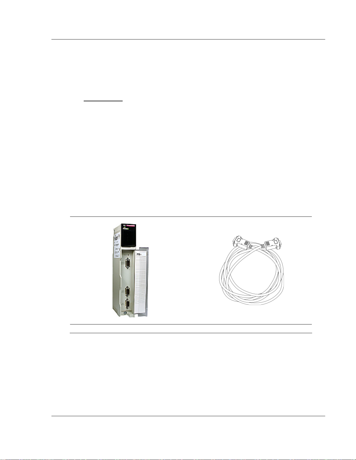
1.1.1 ProTalk Module Carton Contents
ProTalk Module Null Modem Serial Cable
ProSoft Technology, Inc. Page 11 of 181
May 14, 2008
Page 12
PTQ-101M ♦ Quantum Platform Start Here
IEC 60870-5-101 Master Communication Module
1454-9F DB-9 Female to 9 Pos Screw Terminal
adapter (Serial protocol modules only)
ProSoft Solutions CD
Note: The DB-9 Female to 5 Pos Screw Terminal adapter is not required on Ethernet modules and
is therefore not included in the carton with these typ es of modules.
1.1.2 Quantum / Unity Hardware
This guide assumes that you are familiar with the installation and setup of the
Quantum / Unity hardware. The following should be installed, configured and
powered up before proceeding:
Quantum or Unity Processor
Quantum rack
Quantum power supply
Quantum Modbus Plus Network Option Module (NOM Module) (optional)
Quantum to PC programming hardware
NOM Ethernet or Serial connection to PC
1.1.3 PC and PC Software
Windows-based PC with at least one COM port
Quantum programming software installed on machine
or
Concept™ PLC Programming Software version 2.6
or
ProWORX PLC Programming Software
or
UnityPro XL PLC Programming Software
HyperTerminal (used in this guide) This is a communication program that is
included with Microsoft Windows. You can normally find it in Start /
Programs / accessories / Communications.
Note: ProTalk modules are compatible with common Quantum / Unity programming applications,
including Concept and UnityPro XL. For all other programming applications, please contact
technical support.
Page 12 of 181 ProSoft Technology, Inc.
May 14, 2008
Page 13

Configuring the Processor with Concept PTQ-101M ♦ Quantum Platform
IEC 60870-5-101 Master Communication Module
2 Configuring the Processor with Concept
In This Chapter
Information for Concept Version 2.6 Users............................................ 14
Create a New Project ............................................................................15
Add the PTQ Module to the Project .......................................................18
Set up Data Memory in Project.............................................................. 20
How to Set up and Use the Sample Function Block for Concept...........23
Download the Project to the Processor .................................................36
Verify Successful Download .................................................................. 39
The following steps are designed to ensure that the processor is able to transfer
data successfully with the PTQ module. As part of this procedure, you will use
Concept configuration software from Schneider Electric to create a project, add
the PTQ module to the project, set up data memory for the project, and then
download the project to the processor.
Important Note: Concept software does not report whether the PTQ module is present in the rack,
and therefore is not able to report the health status of the module when the module is online with
the Quantum processor. Please take this into account when monitoring the status of the PTQ
module.
ProSoft Technology, Inc. Page 13 of 181
May 14, 2008
Page 14
PTQ-101M ♦ Quantum Platform Configuring the Processor with Concept
IEC 60870-5-101 Master Communication Module
2.1 Information for Concept Version 2.6 Users
This guide uses Concept PLC Programming Software version 2.6 to configure
the Quantum PLC. The ProTalk installation CD includes MDC module
configuration files that help document the PTQ installation. Although not required,
these files should be installed before proceeding to the next section.
2.1.1 Installing MDC Configuration Files
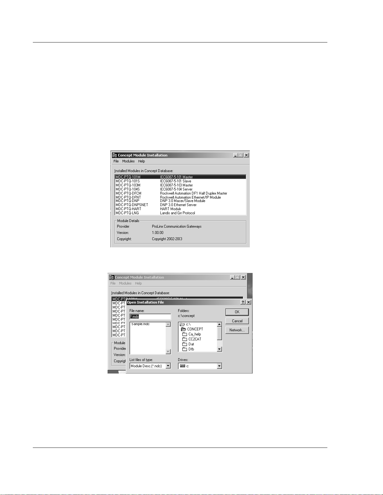
1 From a PC with Concept 2.6 installed, choose Start / Programs / Concept /
ModConnect Tool.
This action opens the Concept Module Installation dialog box.
2 Choose File / Open Installation File.
This action opens the Open Installation File dialog box:
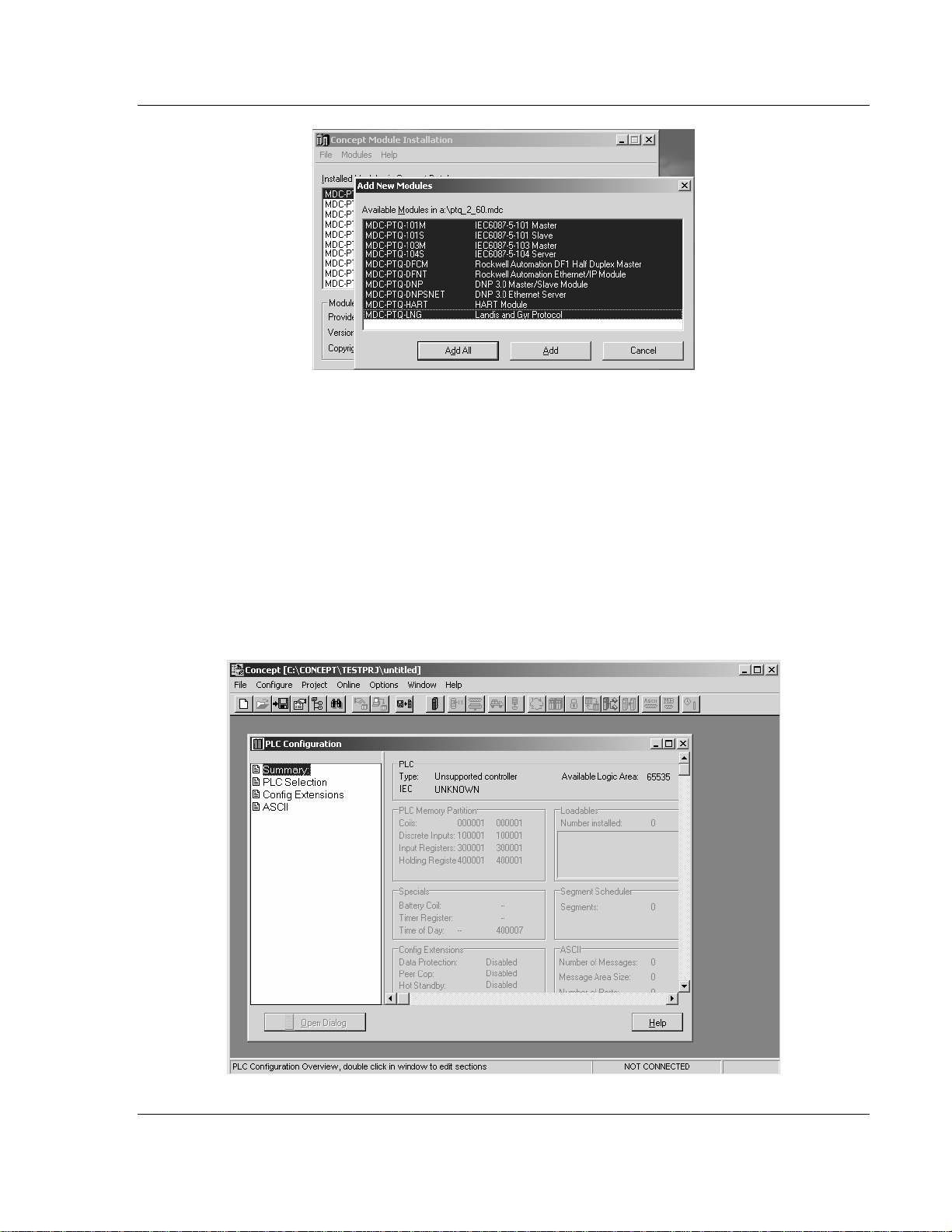
3 If you are using a Quantum processor, you will need the MDC files. In the
Open Installation File dialog box, navigate to the MDC Files directory on the
ProTalk CD.
4 Choose the MDC file and help file for your version of Concept:
o Concept 2.6 users: select PTQ_2_60.mdc and PTQMDC.hlp
o Concept 2.5 users: select PTQ_2_50.mdc and PTQMDC.hlp.
Select the files that go with the Concept version you are using, and then click
OK. This action opens the add New Modules dialog box.
Page 14 of 181 ProSoft Technology, Inc.
May 14, 2008
Page 15
Configuring the Processor with Concept PTQ-101M ♦ Quantum Platform
IEC 60870-5-101 Master Communication Module
5 Click the add all button. A series of message boxes may appear during this
process. Click Yes or OK for each message that appears.
6 When the process is complete, open the File menu and choose Exit to save
your changes.
2.2 Create a New Project
This phase of the setup procedure must be performed on a computer that has
the Concept configuration software installed.
1 From your computer, choose Start / Programs / Concept V2.6 XL.EN /
Concept. This action opens the Concept window.
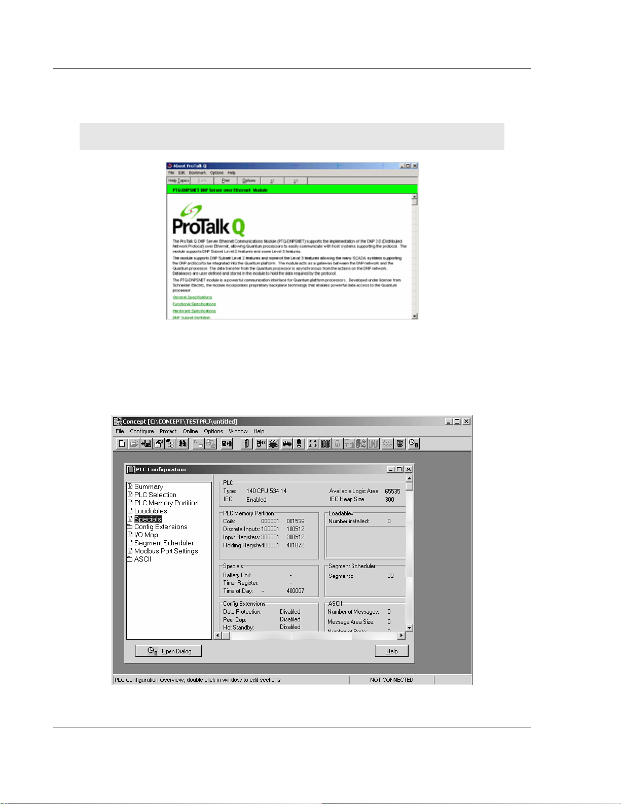
2 Open the File menu, and then choose New Project. This action opens the
PLC Configuration dialog box.
ProSoft Technology, Inc. Page 15 of 181
May 14, 2008
Page 16
PTQ-101M ♦ Quantum Platform Configuring the Processor with Concept
IEC 60870-5-101 Master Communication Module
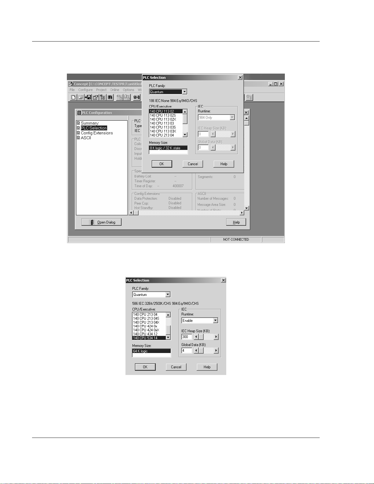
3 In the list of options on the left side of this dialog box, double-click the PLC
Selection folder. This action opens the PLC Selection dialog box.
4 In the CPU/Executive pane, use the scroll bar to locate and select the PLC to
configure.
Page 16 of 181 ProSoft Technology, Inc.
May 14, 2008
Page 17
Configuring the Processor with Concept PTQ-101M ♦ Quantum Platform
IEC 60870-5-101 Master Communication Module
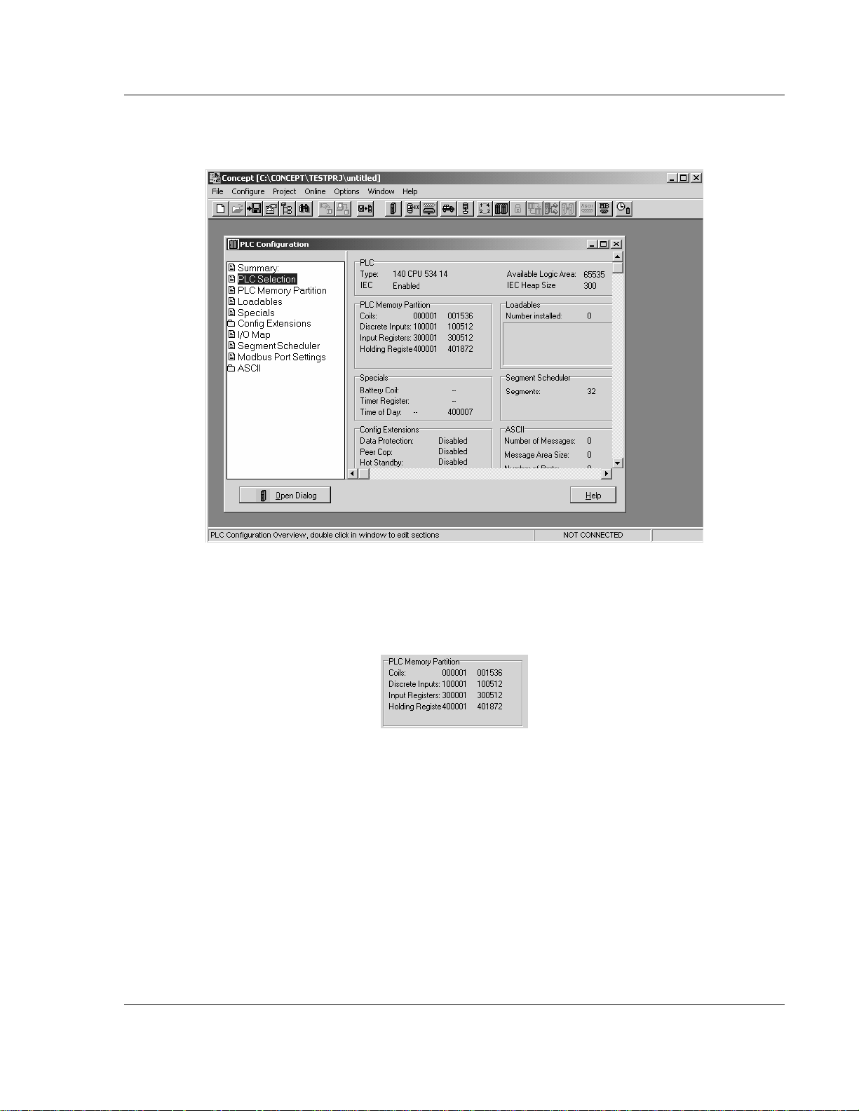
5 Click OK. This action opens the PLC Configuration dialog box, populated with
the correct values for the PLC you selected.
6 Make a note of the holding registers for the module. You will need this
information when you modify your application as outlined in the ProTalk
application Reference Guides. The Holding Registers are displayed in the
PLC Memory Partition pane of the PLC Configuration dialog box.
ProSoft Technology, Inc. Page 17 of 181
May 14, 2008
Page 18
PTQ-101M ♦ Quantum Platform Configuring the Processor with Concept
IEC 60870-5-101 Master Communication Module
2.3 Add the PTQ Module to the Project
The next step is to add one or more of the PTQ modules to the Project. To add
modules:
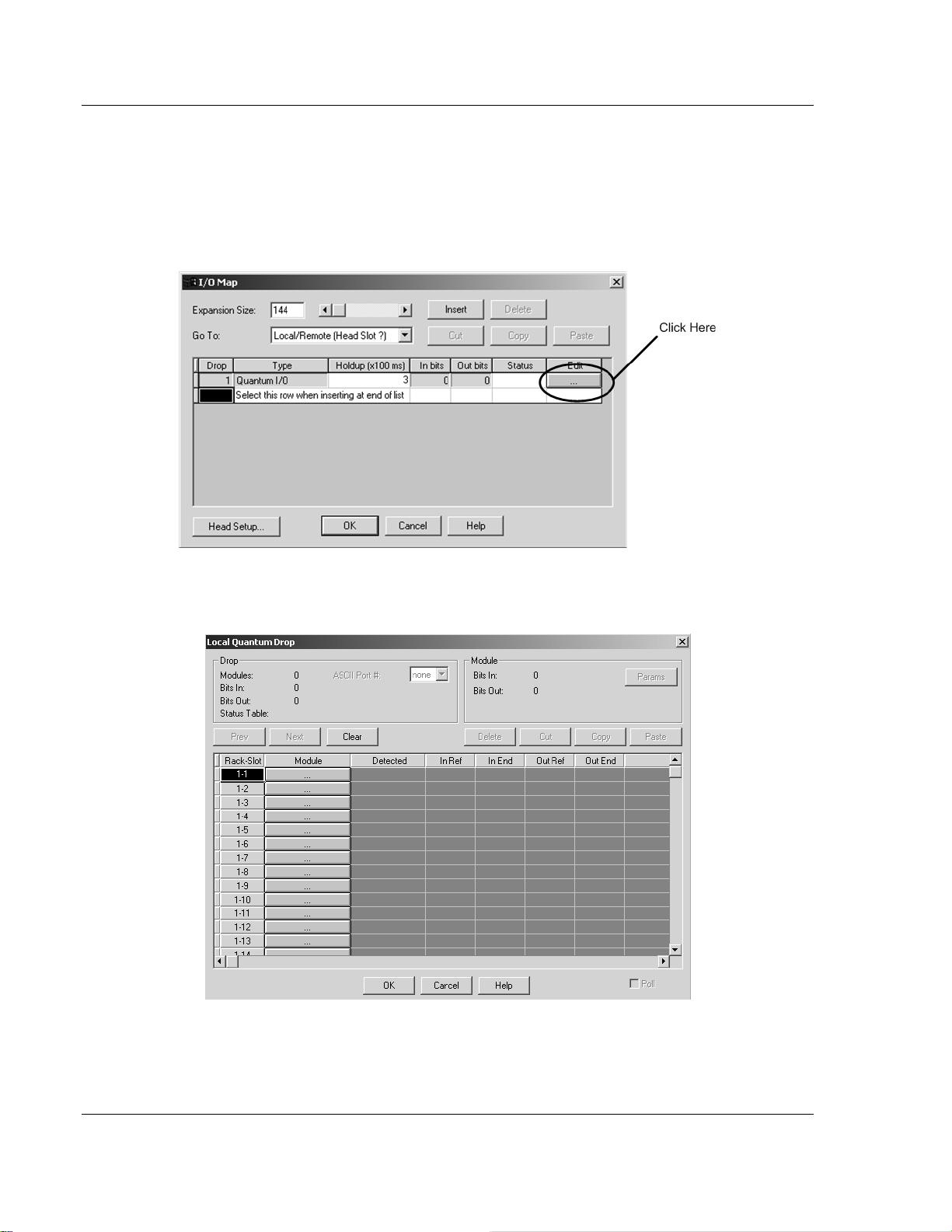
1 In the list of options on the left side of the PLC Configuration dialog box,
double-click I/O Map. This action opens the I/O Map dialog box.
2 Click the Edit button to open the Local Quantum Drop dialog box. This dialog
box is where you identify rack and slot locations.
Page 18 of 181 ProSoft Technology, Inc.
May 14, 2008
Page 19
Configuring the Processor with Concept PTQ-101M ♦ Quantum Platform
IEC 60870-5-101 Master Communication Module
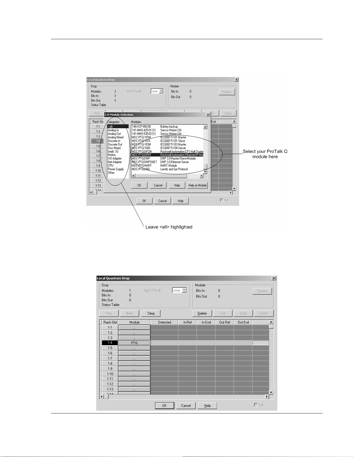
3 Click the Module button next to the rack/slot position where the ProTalk
module will be installed. This action opens the I/O Module Selection dialog
box.
4 In the Modules pane, use the scroll bar to locate and select the ProTalk
module, and then click OK. This action copies the description of the ProTalk
module next to the assigned rack and slot number of the Local Quantum
Drop dialog box.
ProSoft Technology, Inc. Page 19 of 181
May 14, 2008
Page 20
PTQ-101M ♦ Quantum Platform Configuring the Processor with Concept
IEC 60870-5-101 Master Communication Module
5 Repeat steps 3 through 5 for each ProTalk module you plan to install. When
you have finished installing your ProTalk modules, click OK to save your
settings. Click Yes to confirm your settings.
Tip: Select a module, and then click the Help on Module button for help pages.
2.4 Set up Data Memory in Project
1 In the list of options on the left side of the PLC Configuration dialog box,
double-click Specials.
Page 20 of 181 ProSoft Technology, Inc.
May 14, 2008
Page 21
Configuring the Processor with Concept PTQ-101M ♦ Quantum Platform
IEC 60870-5-101 Master Communication Module
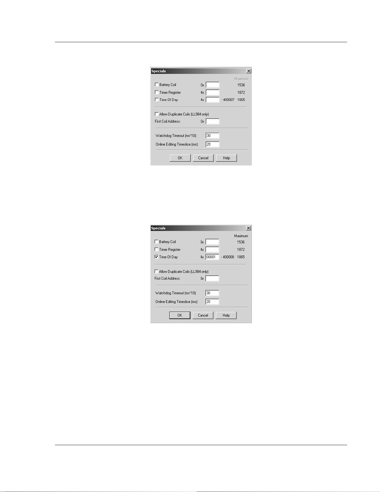
2 This action opens the Specials dialog box.
Selecting the Time of Day
1 Select (check) the Time of Day box, and then enter the value 00001 as
shown in the following example. This value sets the first time of day register
to 400001.
2 Click OK to save your settings and close the Specials dialog box.
ProSoft Technology, Inc. Page 21 of 181
May 14, 2008
Page 22
PTQ-101M ♦ Quantum Platform Configuring the Processor with Concept
IEC 60870-5-101 Master Communication Module
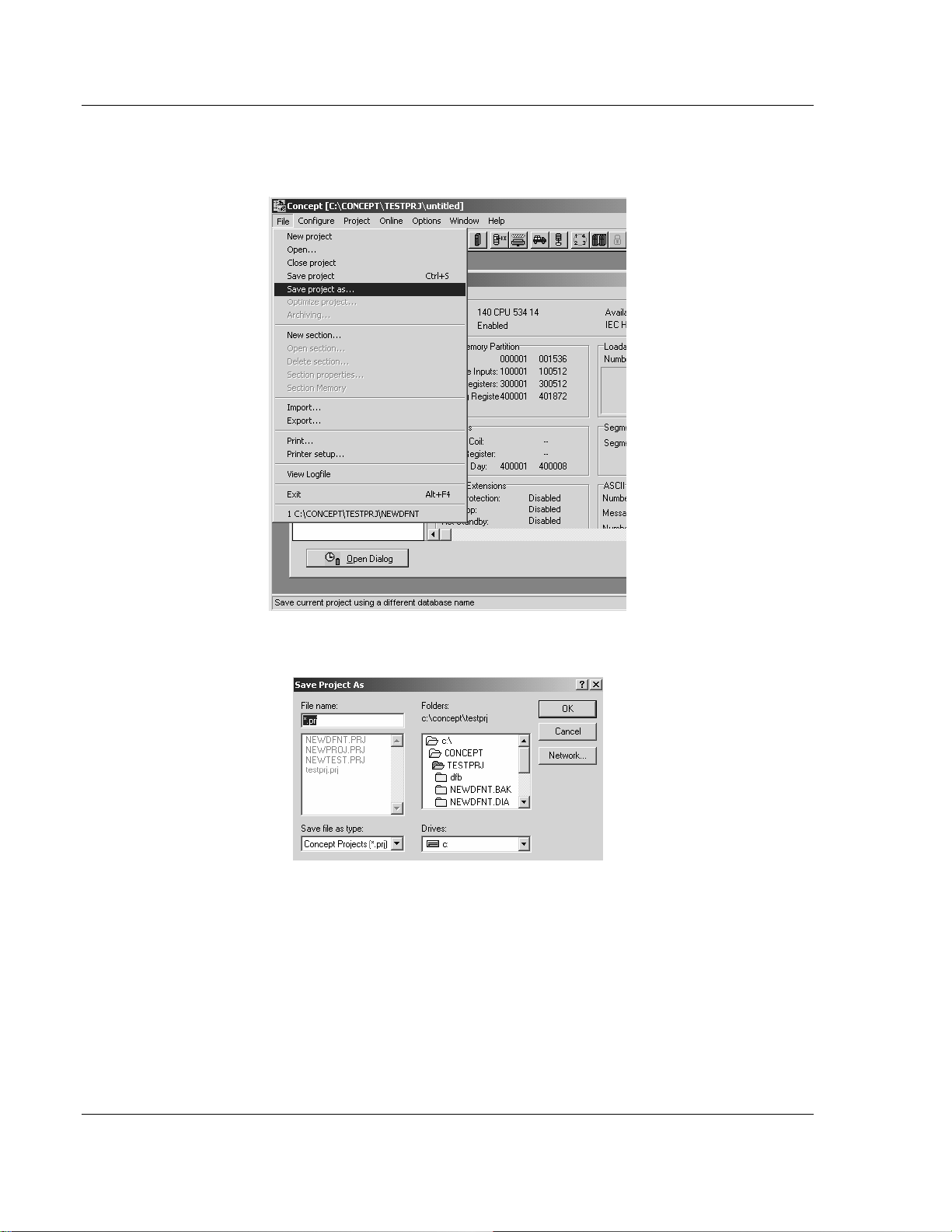
Saving your project
1 In the PLC Configuration dialog box, choose File / Save project as.
2 This action opens the Save Project as dialog box.
3 Name the project, and then click OK to save the project to a file.
Page 22 of 181 ProSoft Technology, Inc.
May 14, 2008
Page 23
Configuring the Processor with Concept PTQ-101M ♦ Quantum Platform
IEC 60870-5-101 Master Communication Module
2.5 How to Set up and Use the Sample Function Block for Concept
2.5.1 EVENTFB Function Block Overview
The purpose of the EVENTFB sample function block is to transfer the events into
a buffer that consists of an array of elements that stores all data in a convenient
format for the user. The block 9903 passes data into a compacted format thus
occupying the minimum amount of registers. For example, the block 9903
originally reserves the same register for Hour and Minute (one byte for each
value), so the user application would need to extract each value. The EVENTFB
sample function block already extracts each event value into a separate register.
The following illustration shows the structure of each element of the buffer
(extracted from the data type definition file).
TYPE EVENT101:
STRUCT
Session : WORD; (* Session configured for this Master *)
Sector : WORD; (* Sector configured for this session *)
COT : WORD; (* Cause of transmission of the event message *)
Reserved : WORD; (* Reserved*)
PointIndex : ARRAY[0..1] OF WORD; (* This is the point index in remote device
that generated the event*)
ASDU : WORD; (* ASDU Type *)
Milliseconds: UINT; (* Timestamp - milliseconds *)
Seconds: UINT; (* Timestamp - Seconds *
Minutes: BYTE; (* Timestamp - minutes and hours *)
Hours: BYTE (* Timestamp - minutes and hours *)
Month : BYTE; (* This contains the month of the event occurred*)
Day : BYTE; (* This contains the day of the Event occurred*)
Year: WORD ; (* This contains the year the event occurred *)
Qualifier: WORD; (* Point qualifier, quality/sequence value see protocol
specification*)
Value: ARRAY[0..1] OF WORD; (* Data value - data size depends on ASDU type
*)
END_STRUCT;
END_TYPE
The data structure that stores the incoming events consists on a circular buffer
that can store up to 199 events. So the buffer consists on an array of 199
"EVENT101" elements presented previously. The element index can vary from 0
to 199. If the last event updated was located at index 199 then the next event will
be copied to index 0.
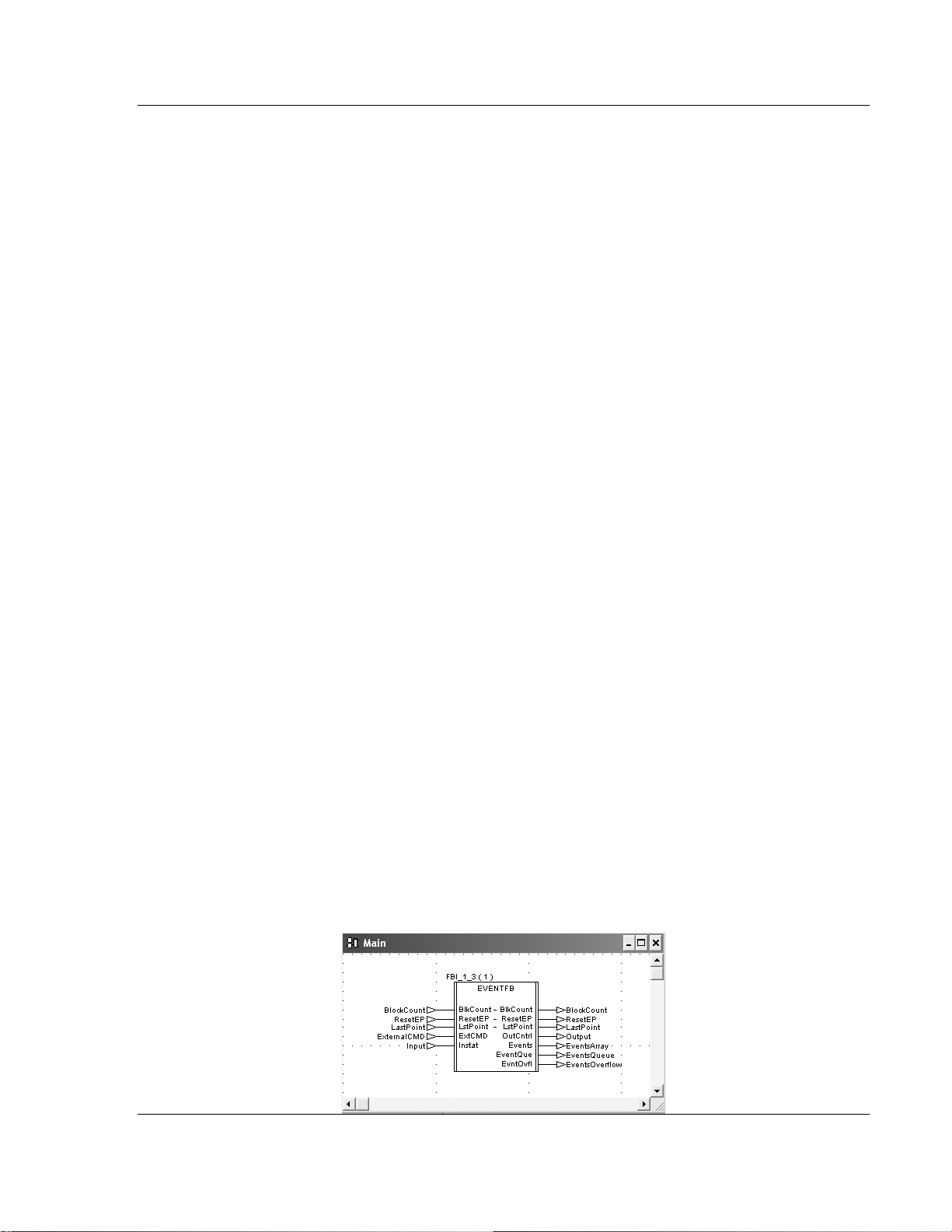
The following illustration shows an instance example of the EVENTFB function
block.
ProSoft Technology, Inc. Page 23 of 181
May 14, 2008
Page 24

PTQ-101M ♦ Quantum Platform Configuring the Processor with Concept
IEC 60870-5-101 Master Communication Module
The EVENTFB function block contains the following PINs.
PIN PIN Type Data Type Description
Instat input WORD64
ResetEP input/output INT
Events Output EVENTSTRUCT
BlkCount Input/Output INT
LstPoint Input/Output INT
ExtCmd Input WORD
OutCntrl Output WORD64
EventQue Output WORD
EvntOvfl Output WORD
Stores the memory area updated by block 9903.
The start address must point to the same start
address defined for block 9903 backplane data
exchange (Point Address parameter).
Move a value of one to reset the event pointer.
This will cause the next event to be written to
index 0 at the circular buffer. The register will be
automatically reset to zero after the request was
processed. This register should be only used for
very specific applications (because the circular
buffer automatically changes the element pointer
from 199 to 0 after the maximum index was
reached)
Circular buffer that stores all received events in
a convenient format for the user application. It
can store up to 200 events (index varies from 0
to 199). After event 199 is updated the next
event to be received will be automatically
updated at index 0.
Incremented after a block is received (and after
the events in that block have been read into the
circular buffer). The maximum value for this
counter is 1000 (then it is automatically reset to
0)
Pointer to the last event index read from the
module. For example, if last event was updated
at index 5 then this value will have the same
value.
This external command is used so user can
issue different commands while the module
receiving events.
Stores data to be sent from the processor to the
module the start address it should match what
you configured your backplane exchange to
start.
Indicates how many events are in the queue to
be read.
This will be set to yes (1) if the overflow flag is
set due to 199 events in the queue waiting to be
read.
Before You Begin
1 Make sure that your computer has the Concept Programming Unit installed.
2 The PTQ-101M firmware revision must support the event pass-thru
functionality. This feature is available for version 1.12 or later. Refer to the "V"
menu for the SOFTWARE REVISION LEVEL (page 97) value at the debug
menu of the PTQ-101M module.
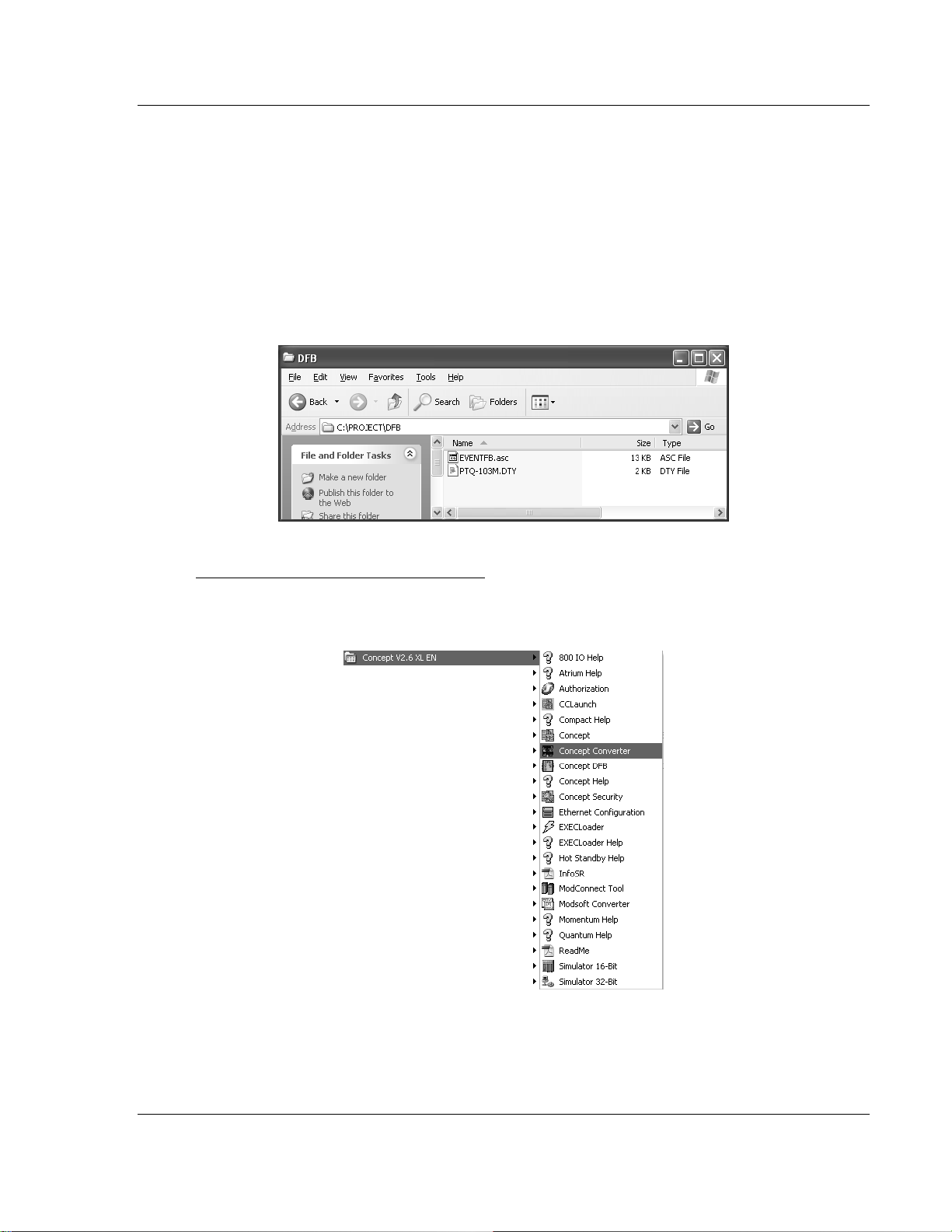
3 Using Windows Explorer create a folder for your Concept project with a
"DFB" subfolder. This procedure will consider as an example the folder
C:\PROJECT\DFB, where:
o C:\PROJECT- will store the main Concept project (.PRJ)
Page 24 of 181 ProSoft Technology, Inc.
May 14, 2008
Page 25
Configuring the Processor with Concept PTQ-101M ♦ Quantum Platform
IEC 60870-5-101 Master Communication Module
o C:\PROJECT\DFB - will store the data type definition file (PTQ-
101M.DTY) and the function block that will be presented later at this
document.
4 Refer to the CD-ROM or to the web site for the
PTQ101MConcept_Block9903.zip file and extract the following files:
o EVENTFB.asc (function block)
o PTQ-101M.DTY (data type definition)
Use Windows Explorer to move these files to C:\PROJECT\DFB as shown in
the following illustration.
Convert the EVENTFB Function Block
1 Start the Concept v2.6 XL EN - Concept Converter as shown in the following
illustration.
ProSoft Technology, Inc. Page 25 of 181
May 14, 2008
Page 26
PTQ-101M ♦ Quantum Platform Configuring the Processor with Concept
IEC 60870-5-101 Master Communication Module
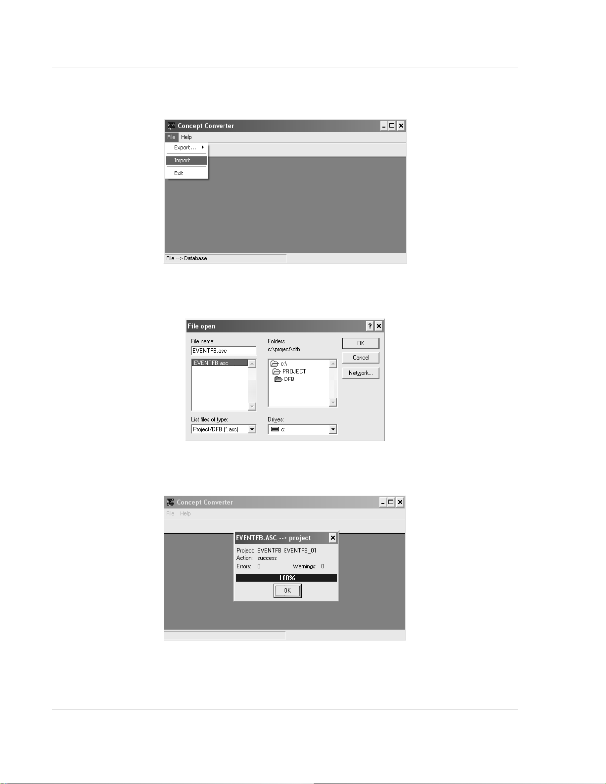
2 When the Concept Converter windows is displayed, open the File menu, and
then choose Import
3 Select the EVENTFB.asc file located at C:\PROJECT\DFB as shown in the
following illustration.
4 When the importing procedure is completed you will observe the following
confirmation screen:
Page 26 of 181 ProSoft Technology, Inc.
May 14, 2008
Page 27
Configuring the Processor with Concept PTQ-101M ♦ Quantum Platform
IEC 60870-5-101 Master Communication Module
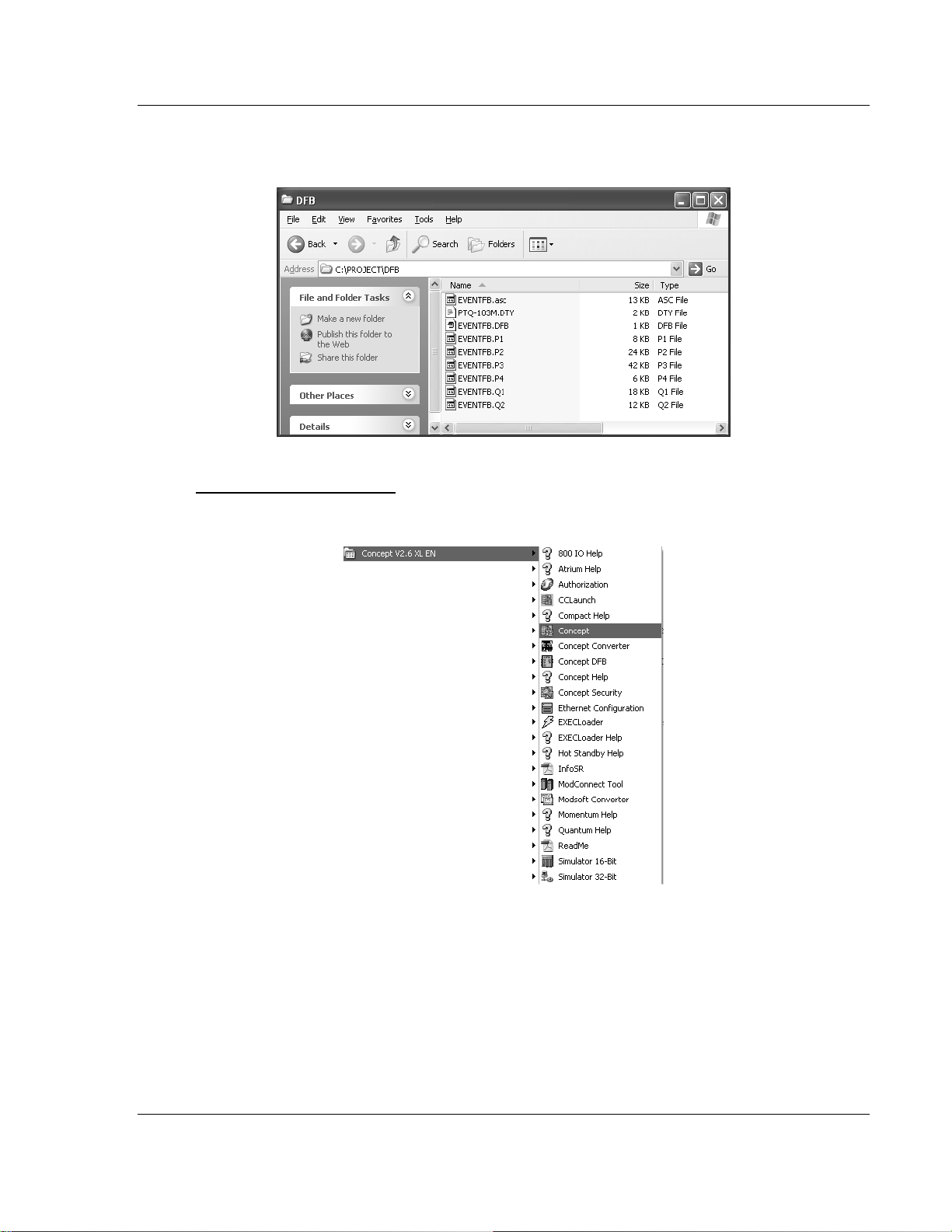
5 Close the Concept Converter tool. Now you can refer to C:\PROJECT\DFB to
check that the function block (.DFB) was exported and is ready to be used.
Setup the Concept Project
1 Start the Concept software as shown in the following illustration...
ProSoft Technology, Inc. Page 27 of 181
May 14, 2008
Page 28
PTQ-101M ♦ Quantum Platform Configuring the Processor with Concept
IEC 60870-5-101 Master Communication Module
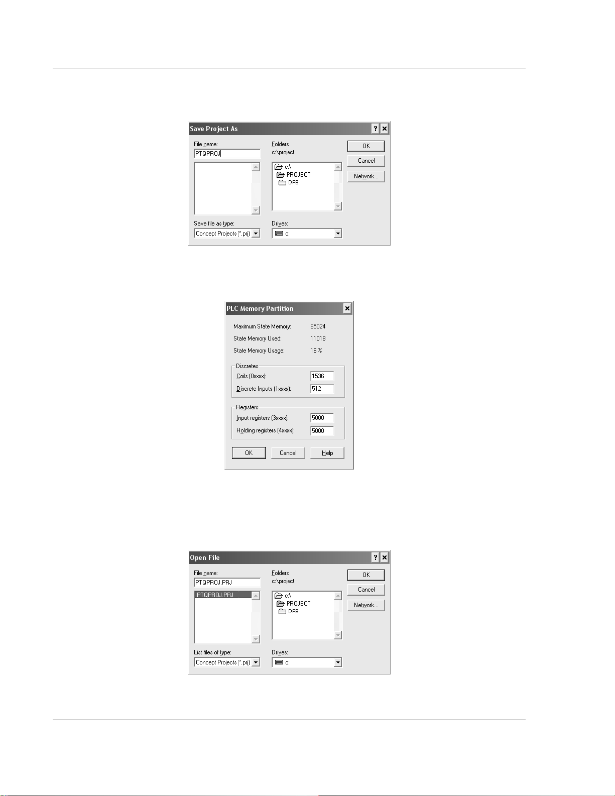
2 Create a new project and save it at the C:\PROJECT folder. For this example
we will consider the project name as PTQPROJ.
3 At PLC Memory Partition make sure that the processor memory range is
configured large enough for the PTQ-101M backplane usage.
4 On the File menu, choose Close Project. Open the File menu again and then
choose Open to open the PTQPROJ file again. This step allows the Concept
application to recognize the new data types defined at the PTQ-101M.DTY
file.
Page 28 of 181 ProSoft Technology, Inc.
May 14, 2008
Page 29
Configuring the Processor with Concept PTQ-101M ♦ Quantum Platform
IEC 60870-5-101 Master Communication Module
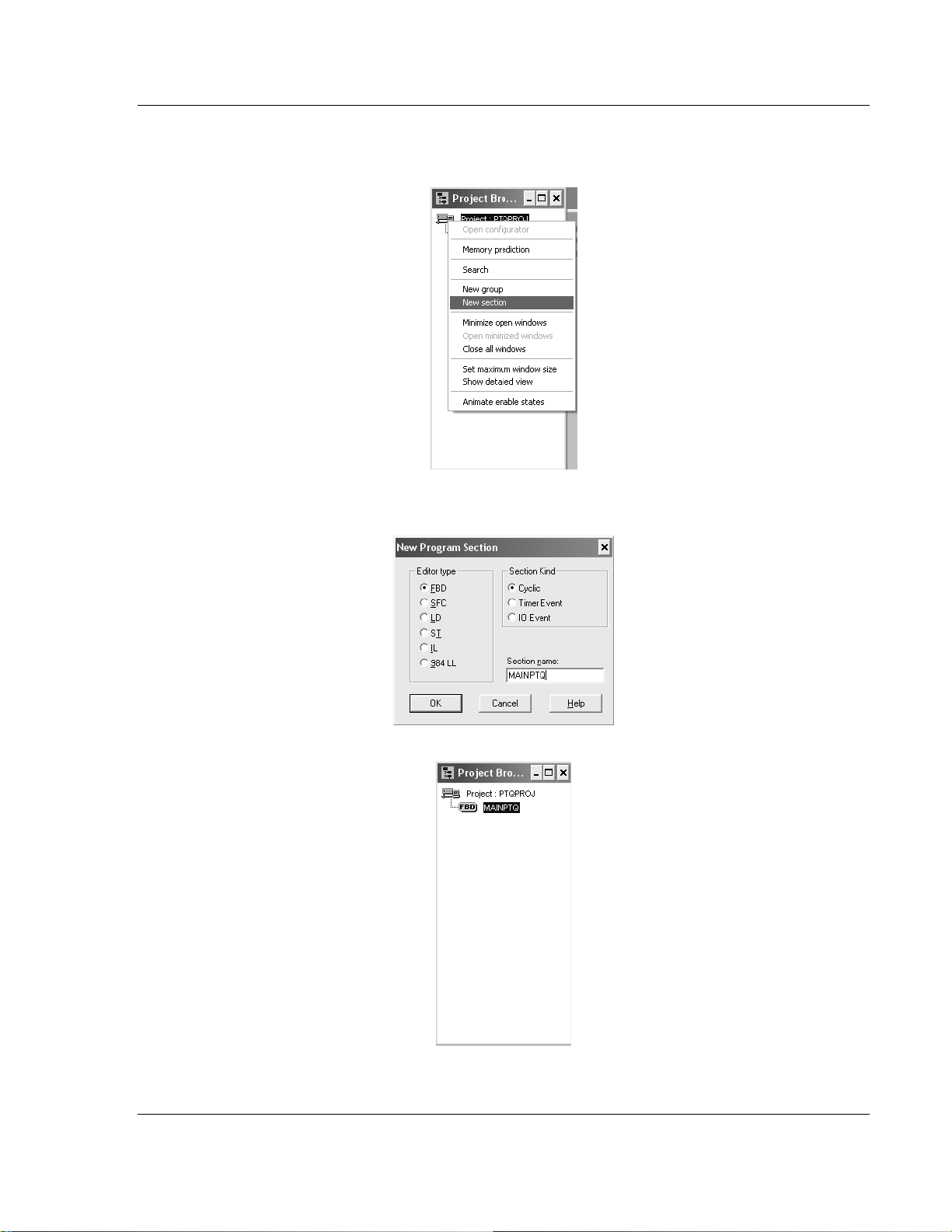
5 Select Project Browser. Select Project: PTQPROJ and click the right mouse
button to open a shortcut menu. On the shortcut menu, choose New Section
6 Select FBD. The procedure will refer to this section as MAINPTQ. Click OK
ProSoft Technology, Inc. Page 29 of 181
May 14, 2008
Page 30
PTQ-101M ♦ Quantum Platform Configuring the Processor with Concept
IEC 60870-5-101 Master Communication Module
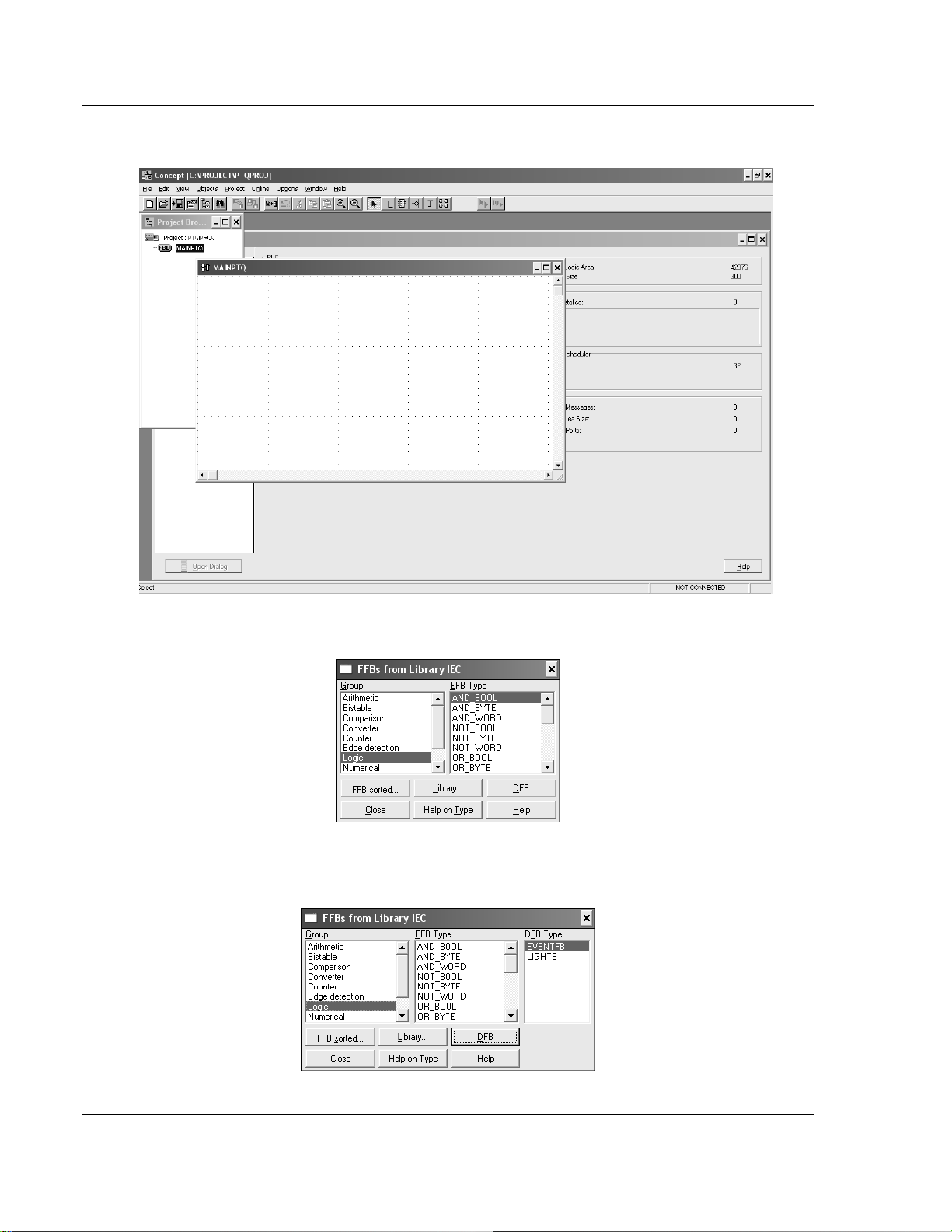
7 Double-Click the section to display the FBD section:
8 Select Objects-FFB Selection…
9 Click the DFB button and select the EVENTFB function block shown in the
following illustration... Then close the window.
Page 30 of 181 ProSoft Technology, Inc.
May 14, 2008
Page 31

Configuring the Processor with Concept PTQ-101M ♦ Quantum Platform
IEC 60870-5-101 Master Communication Module
Now you should see the EVENTFB function block at the FBD section:
This step will create variables to be associated to the function block PINs. We will
start with the Instat PIN. The variable for this PIN must point to the same start
address where block 9903 will be copied to. For this example we are considering
the following configuration for block 9903:
3x Register Start : 1 #3x start register where data moved from module
to processor (1 to n)
This implies that the variable associated to PIN Instat must also start at the
same register address (300001 for this example).
As the Instat PIN will start same as 3x
The variable that associated with PIN OutCntrl must start at the same register
address 400001
4x Register Start : 1 #4x start register where data moved from
processor
to module (1 to n)
This example will use the same name as the PIN.
ProSoft Technology, Inc. Page 31 of 181
May 14, 2008
Page 32

PTQ-101M ♦ Quantum Platform Configuring the Processor with Concept
IEC 60870-5-101 Master Communication Module
1 Click the Variable declaration button to open the Variable Editor dialog box.
2 Click OK and you should see the new variable associated to the Instat PIN:
3 Repeat for OutCntrl Pin to use for Output.
4 Repeat the last item for the other PINS (it is not necessary to associate any
memory address to the other variables).
Page 32 of 181 ProSoft Technology, Inc.
May 14, 2008
Page 33

Configuring the Processor with Concept PTQ-101M ♦ Quantum Platform
IEC 60870-5-101 Master Communication Module
Download the Concept Project
1 Select Online-Download to download the Concept Project. Make sure that the
IEC program sections checkbox is selected:
2 When the download is completed you should see the following window. Click
Yes.
ProSoft Technology, Inc. Page 33 of 181
May 14, 2008
Page 34

PTQ-101M ♦ Quantum Platform Configuring the Processor with Concept
IEC 60870-5-101 Master Communication Module
Using the EVENTFB Function Block
In order to show how the function block can be used we will create the following
Template. This template shows the BlkCount, LstPoint, ResetEP, ExternalCMD
variables and also the first two event elements (Events.Event[0] and
Events.Event[1]):
In this example, the remote device has sent two events with timestamp to the
module (in same block 9903). The following shows an example of how the
variables associated to the EVENTFB function block would be updated.
BlkCount: shows a value of 1 because the processor has received two
Events in one block.
LstPoint: shows a value of 1 because the last element that was updated has
an index of 1 (Events.Event[1]).
Events.Event[0]: shows the first event received from the module
Page 34 of 181 ProSoft Technology, Inc.
May 14, 2008
Page 35

Configuring the Processor with Concept PTQ-101M ♦ Quantum Platform
IEC 60870-5-101 Master Communication Module
Events.Event[1]: shows the second event received from the module
ProSoft Technology, Inc. Page 35 of 181
May 14, 2008
Page 36

PTQ-101M ♦ Quantum Platform Configuring the Processor with Concept
IEC 60870-5-101 Master Communication Module
2.6 Download the Project to the Processor
The next step is to download (copy) the project file to the Quantum Processor.
1 Use the null modem cable to connect your PC's serial port to the Quantum
processor, as shown in the following illustration.
Note: You can use a Modbus Plus Network Option Module (NOM Module) module in place of the
serial port if necessary.
2 Open the PLC menu, and then choose Connect.
Page 36 of 181 ProSoft Technology, Inc.
May 14, 2008
Page 37

Configuring the Processor with Concept PTQ-101M ♦ Quantum Platform
IEC 60870-5-101 Master Communication Module
3 In the PLC Configuration dialog box, open the Online menu, and then choose
Connect. This action opens the Connect to PLC dialog box.
4 Leave the default settings as shown and click OK.
Note: Click OK to dismiss any message boxes that appear during the connection process.
5 In the PLC Configuration window, open the Online menu, and then choose
Download. This action opens the Download Controller dialog box.
ProSoft Technology, Inc. Page 37 of 181
May 14, 2008
Page 38

PTQ-101M ♦ Quantum Platform Configuring the Processor with Concept
IEC 60870-5-101 Master Communication Module
6 Click all, and then click Download. If a message box appears indicating that
the controller is running, click Yes to shut down the controller. The Download
Controller dialog box displays the status of the download as shown in the
following illustration.
7 When the download is complete, you will be prompted to restart the
controller. Click Yes to restart the controller.
Page 38 of 181 ProSoft Technology, Inc.
May 14, 2008
Page 39

Configuring the Processor with Concept PTQ-101M ♦ Quantum Platform
IEC 60870-5-101 Master Communication Module
2.7 Verify Successful Download
The final step is to verify that the configuration changes you made were received
successfully by the module, and to make some adjustments to your settings.
1 In the PLC Configuration window, open the Online menu, and then choose
Online Control Panel. This action opens the Online Control Panel dialog box.
2 Click the Set Clock button to open the Set Controller's Time of Day Clock
dialog box.
3 Click the Write Panel button. This action updates the date and time fields in
this dialog box. Click OK to close this dialog box and return to the previous
window.
4 Click Close to close the Online Control Panel dialog box.
ProSoft Technology, Inc. Page 39 of 181
May 14, 2008
Page 40

PTQ-101M ♦ Quantum Platform Configuring the Processor with Concept
IEC 60870-5-101 Master Communication Module
5 In the PLC Configuration window, open the Online menu, and then choose
Reference Data Editor. This action opens the Reference Data Editor dialog
box. On this dialog box, you will add preset values to data registers that will
later be monitored in the ProTalk module.
6 Place the cursor over the first address field, as shown in the following
illustration.
7 In the PLC Configuration window, open the Templates menu, and then
choose Insert addresses. This action opens the Insert addresses dialog box.
8 On the Insert addresses dialog box, enter the values shown in the following
illustration, and then click OK.
Page 40 of 181 ProSoft Technology, Inc.
May 14, 2008
Page 41

Configuring the Processor with Concept PTQ-101M ♦ Quantum Platform
IEC 60870-5-101 Master Communication Module
9 Notice that the template populates the address range, as shown in the
following illustration. Place your cursor as shown in the first blank address
field below the addresses you just entered.
10 Repeat steps 6 through 9, using the values in the following illustration:
ProSoft Technology, Inc. Page 41 of 181
May 14, 2008
Page 42

PTQ-101M ♦ Quantum Platform Configuring the Processor with Concept
IEC 60870-5-101 Master Communication Module
11 In the PLC Configuration window, open the Online menu, and then choose
animate. This action opens the RDE Template dialog box, with animated
values in the Value field.
12 Verify that values shown are cycling, starting from address 400065 on up.
13 In the PLC Configuration window, open the Templates menu, and then
choose Save Template as. Name the template ptqclock, and then click OK to
save the template.
14 In the PLC Configuration window, open the Online menu, and then choose
Disconnect. At the disconnect message, click Yes to confirm your choice.
At this point, you have successfully
Created and downloaded a Quantum project to the PLC
Preset values in data registers that will later be monitored in the ProTalk
module.
You are now ready to complete the installation and setup of the ProTalk module.
Page 42 of 181 ProSoft Technology, Inc.
May 14, 2008
Page 43

Configuring the Processor with ProWORX PTQ-101M ♦ Quantum Platform
IEC 60870-5-101 Master Communication Module
3 Configuring the Processor with ProWORX
When you use ProWORX 32 software to configure the processor, use the
example SaF file provided on the ProTalk Solutions CD-ROM.
Important Note: Proworx software does not report whether the PTQ module is present in the rack,
and therefore is not able to report the health status of the module when the module is online with
the Quantum processor. Please take this into account when monitoring the status of the PTQ
module.
1 Run the Schneider_alliances.exe application that is installed with the
Proworx 32 software:
2 Click on Import…
ProSoft Technology, Inc. Page 43 of 181
May 14, 2008
Page 44

PTQ-101M ♦ Quantum Platform Configuring the Processor with ProWORX
IEC 60870-5-101 Master Communication Module
3 Select the .SaF File that is located at the CD-ROM shipped with the PTQ
module.
4 After you click on Open you should see the PTQ modules imported (select
I/O series as Quantum):
Page 44 of 181 ProSoft Technology, Inc.
May 14, 2008
Page 45

Configuring the Processor with ProWORX PTQ-101M ♦ Quantum Platform
IEC 60870-5-101 Master Communication Module
Now you can close the Schneider alliances application and run the Proworx 32
software. At the Traffic Cop section, select the PTQ module to be inserted at the
slot:
ProSoft Technology, Inc. Page 45 of 181
May 14, 2008
Page 46

PTQ-101M ♦ Quantum Platform Configuring the Processor with ProWORX
IEC 60870-5-101 Master Communication Module
Page 46 of 181 ProSoft Technology, Inc.
May 14, 2008
Page 47

Configuring the Processor with UnityPro XL PTQ-101M ♦ Quantum Platform
IEC 60870-5-101 Master Communication Module
4 Configuring the Processor with UnityPro XL
In This Chapter
Create a New Project ............................................................................47
Add the PTQ Module to the Project .......................................................49
How to Set up and Use the Sample Function Block for Unity................ 51
Build the Project .................................................................................... 62
Connect Your PC to the Processor ....................................................... 63
Download the Project to the Processor .................................................65
The following steps are designed to ensure that the processor (Quantum or
Unity) is able to transfer data successfully with the PTQ module. As part of this
procedure, you will use UnityPro XL to create a project, add the PTQ module to
the project, set up data memory for the project, and then download the project to
the processor.
4.1 Create a New Project
The first step is to open UnityPro XL and create a new project.
1 In the New Project dialog box, choose the CPU type. In the following
illustration, the CPU is 140 CPU 651 60. Choose the processor type that
matches your own hardware configuration, if it differs from the example. Click
OK to continue.
ProSoft Technology, Inc. Page 47 of 181
May 14, 2008
Page 48

PTQ-101M ♦ Quantum Platform Configuring the Processor with UnityPro XL
IEC 60870-5-101 Master Communication Module
2 The next step is to add a power supply to the project. In the Project Browser,
expand the Configuration folder, and then double-click the 1:LocalBus icon.
This action opens a graphical window showing the arrangement of devices in
your Quantum rack.
3 Select the rack position for the power supply, and then click the right mouse
button to open a shortcut menu. On the shortcut menu, choose New Device..
Page 48 of 181 ProSoft Technology, Inc.
May 14, 2008
Page 49

Configuring the Processor with UnityPro XL PTQ-101M ♦ Quantum Platform
IEC 60870-5-101 Master Communication Module
4 Expand the Supply folder, and then select your power supply from the list.
Click OK to continue.
5 Repeat these steps to add any additional devices to your Quantum Rack.
4.2 Add the PTQ Module to the Project
The next step is to add the PTQ module.
1 Expand the Communication tree, and select GEN NOM. This module type
provides extended communication capabilities for the Quantum system, and
allows communication between the PLC and the PTQ module without
requiring additional programming.
ProSoft Technology, Inc. Page 49 of 181
May 14, 2008
Page 50

PTQ-101M ♦ Quantum Platform Configuring the Processor with UnityPro XL
IEC 60870-5-101 Master Communication Module
2 Next, enter the module personality value. The correct value for this ProTalk
module is 1091 decimal (0443 hex).
3 Before you can save the project in UnityProXL, you must validate the
modifications. Open the Edit menu, and then choose Validate. If no errors are
reported, you can save the project.
4 Save the project.
Page 50 of 181 ProSoft Technology, Inc.
May 14, 2008
Page 51

Configuring the Processor with UnityPro XL PTQ-101M ♦ Quantum Platform
IEC 60870-5-101 Master Communication Module
4.3 How to Set up and Use the Sample Function Block for Unity
4.3.1 EVENTFB Function Block Overview
The purpose of the EVENTFB sample function block is to transfer the events into
a buffer that consists of an array of elements that stores all data in a convenient
format for the user. The block 9903 passes data into a compacted format thus
occupying the minimum amount of registers. The EVENTFB sample function
block already extracts each event value into a separate register.
The following illustration shows the structure of each element of the buffer
(extracted from the data type definition file):
The data structure that stores the incoming events consists of a circular buffer
that can store up to 199 events. The buffer consists of an array of 199
"EVENT101" elements presented previously. The element index can vary from 0
to 199. If the last event updated was located at index 199 then the next event will
be copied to index 0.
ProSoft Technology, Inc. Page 51 of 181
May 14, 2008
Page 52

PTQ-101M ♦ Quantum Platform Configuring the Processor with UnityPro XL
IEC 60870-5-101 Master Communication Module
The following illustration shows an instance example of the EVENTFB function
block:
The EVENTFB function block contains the following PINs:
PIN PIN Type Data Type Description
InputStatus input
ResetEP input/output INT
Events Output EVENT101M
BlkCount Input/Output INT
LstPoint Input/Output INT
ExternalCmd Input WORD
Array of
WORD
Stores the memory area updated by block 9903.
The start address must point to the same start
address defined for block 9903 backplane data
exchange (Point Address parameter).
Move a value of one to reset the event pointer.
This will cause the next event to be written to
index 0 at the circular buffer. The register will be
automatically reset to zero after the request was
processed. This register should be only used for
very specific applications (because the circular
buffer automatically changes the element pointer
from 199 to 0 after the maximum index was
reached)
Circular buffer that stores all received events in
a convenient format for the user application. It
can store up to 200 events (index varies from 0
to 199). After event 199 is updated the next
event to be received will be automatically
updated at index 0.
Incremented after a block is received (and after
the events in that block have been read into the
circular buffer). The maximum value for this
counter is 1000 (then it is automatically reset to
0)
Pointer to the last event index read from the
module. For example, if last event was updated
at index 5 then this value will have the same
value.
This external command is used so user can
issue different commands while the module
receiving events.
Page 52 of 181 ProSoft Technology, Inc.
May 14, 2008
Page 53

Configuring the Processor with UnityPro XL PTQ-101M ♦ Quantum Platform
IEC 60870-5-101 Master Communication Module
PIN PIN Type Data Type Description
OutputControl Output
Eventinqueue Output WORD
EventOverflow Output WORD
Array of
WORD
Stores data to be sent from the processor to the
module the start address it should match what
you configured your backplane exchange to
start.
Indicates how many events are in the queue to
be read.
This will be set to yes (1) if the overflow flag is
set due to 199 events in the queue waiting to be
read.
4.3.2 Importing the EVENTFB Function Block
1 Copy the provided function block from the ProSoft Solutions CD-ROM, or
download the EVENTFB.XDB from http://www.prosoft-technology.com. For
this example, save the Function Block in your My Documents folder.
2 In the Project Browser, select Derived FB Types and then click the right
mouse button to open a shortcut menu. On the shortcut menu, choose
Import.
3 This action opens a confirmation dialog box.
4 Click No to discard your changes, unless you are importing this function block
to an existing project, in which case click Yes.
ProSoft Technology, Inc. Page 53 of 181
May 14, 2008
Page 54

PTQ-101M ♦ Quantum Platform Configuring the Processor with UnityPro XL
IEC 60870-5-101 Master Communication Module
5 In the Import dialog box, click the Import button
6 In the Project Browser, expand Derived Data types and verify that the import
was complete.
Page 54 of 181 ProSoft Technology, Inc.
May 14, 2008
Page 55

Configuring the Processor with UnityPro XL PTQ-101M ♦ Quantum Platform
IEC 60870-5-101 Master Communication Module
7 Next, add the FB section to the programs folder.
8 Click OK
ProSoft Technology, Inc. Page 55 of 181
May 14, 2008
Page 56

PTQ-101M ♦ Quantum Platform Configuring the Processor with UnityPro XL
IEC 60870-5-101 Master Communication Module
9 The next step is to add the Function block to the Main section. Open the
EDIT Menu and then choose FFB Input Assistant
10 This action opens the Function Input Assistant dialog box.
Page 56 of 181 ProSoft Technology, Inc.
May 14, 2008
Page 57

Configuring the Processor with UnityPro XL PTQ-101M ♦ Quantum Platform
IEC 60870-5-101 Master Communication Module
11 Click the button to the right of the FFB type field.
12 Click OK to populate the Function Input Assistant dialog box.
ProSoft Technology, Inc. Page 57 of 181
May 14, 2008
Page 58

PTQ-101M ♦ Quantum Platform Configuring the Processor with UnityPro XL
IEC 60870-5-101 Master Communication Module
13 Click OK to dismiss the Function Input Asistant dialog box. Next, click to
select the Main [Mast] section.
14 The next step is to create variables to associate to the function block PINs.
We will start with the Inputstatus PIN. The variable for this PIN must point to
the same start address where block 9903 will be copied to, referring the
Register Start address entry in the module configuration file.
Register Start : 1 #3x start register where data moved from module to
processor (1 to n)
This implies that the variable associated to PIN Inputstatus must also start at
the same register address (%Iw1 for this example).
As the Inputstatus PIN will start same as 3x, the variable associated with PIN
OutputControl must start at the same register address %MW1
4x Register Start : 1 #4x start register where data moved from
processor to module (1 to n)
You must create user variables that match all PINs on the function block. The
following illustration shows an example.
15 Before you can save the project in UnityProXL, you must validate the
modifications. Open the Edit menu, and then choose Validate. If no errors are
reported, you can save the project.
16 Save the project.
17 Download the project and test the function block
Page 58 of 181 ProSoft Technology, Inc.
May 14, 2008
Page 59

Configuring the Processor with UnityPro XL PTQ-101M ♦ Quantum Platform
IEC 60870-5-101 Master Communication Module
4.3.3 Using the EVENTFB Function Block
1 Create variables that match the Event format. When you import the function
block, derived data types will also be imported.
The variable should match the Event 101M type and should match the
following illustration.
ProSoft Technology, Inc. Page 59 of 181
May 14, 2008
Page 60

PTQ-101M ♦ Quantum Platform Configuring the Processor with UnityPro XL
IEC 60870-5-101 Master Communication Module
2 In the animation table, create an array of events to copy all 199 events, block
count, ResetEP, and the last point, which is the index in the array for the last
event to be copied to the array. The following illustration shows that we
received two events in one block (block count=1) and last Point =1..
Page 60 of 181 ProSoft Technology, Inc.
May 14, 2008
Page 61

Configuring the Processor with UnityPro XL PTQ-101M ♦ Quantum Platform
IEC 60870-5-101 Master Communication Module
In this example, the remote device has sent two events with timestamp to the
module (in same block number). The following shows an example of how the
variables associated to the EVENTFB function block would be updated.
BlkCount: shows a value of 2 because the processor has received two blocks
9903
LstPoint: shows a value of 3 because the last element that was updated has
an index of 3.
Events[0]: shows the first event received from the module
Events[3]: shows the Last event received from the module
ProSoft Technology, Inc. Page 61 of 181
May 14, 2008
Page 62

PTQ-101M ♦ Quantum Platform Configuring the Processor with UnityPro XL
IEC 60870-5-101 Master Communication Module
4.4 Build the Project
Whenever you update the configuration of your PTQ module or the processor,
you must import the changed configuration from the module, and then build
(compile) the project before downloading it to the processor.
Note: The following steps show you how to build the project in Unity Pro XL. This is not intended to
provide detailed information on using U nity Pro XL, or debugging your programs. Refer to the
documentation for your processor and for Unity Pro XL for specialized information.
To build (compile) the project:
1 Review the elements of the project in the Project Browser.
2 When you are satisfied that you are ready to download the project, open the
Build menu, and then choose Rebuild all Project. This action builds
(compiles) the project into a form that the processor can use to execute the
instructions in the project file. This task may take several minutes, depending
on the complexity of the project and the resources available on your PC.
3 As the project is built, Unity Pro XL reports its process in a Progress dialog
box, with details appearing in a pane at the bottom of the window. The
following illustration shows the build process under way.
After the build process is completed successfully, the next step is to download
the compiled project to the processor.
Page 62 of 181 ProSoft Technology, Inc.
May 14, 2008
Page 63

Configuring the Processor with UnityPro XL PTQ-101M ♦ Quantum Platform
IEC 60870-5-101 Master Communication Module
4.5 Connect Your PC to the Processor
The next step is to connect to the processor so that you can download the project
file. The processor uses this project file to communicate over the backplane to
modules identified in the project file.
Note: If you have never connected from the PC to your process or b efore, you must verify that the
necessary port drivers are installed and available to UnityPro XL.
To verify address and driver settings in UnityPro XL:
1 Open the PLC menu, and choose Standard Mode. This action turns off the
PLC Simulator, and allows you to communicate directly with the Quantum or
Unity hardware.
2 Open the PLC menu, and choose Set address... This action opens the Set
address dialog box. Open the Media dropdown list and choose the
connection type to use (TCPIP or USB).
ProSoft Technology, Inc. Page 63 of 181
May 14, 2008
Page 64

PTQ-101M ♦ Quantum Platform Configuring the Processor with UnityPro XL
IEC 60870-5-101 Master Communication Module
3 If the Media dropdown list does not contain the connection method you wish
to use, click the Communication Parameters button in the PLC area of the
dialog box. This action opens the PLC Communication Parameters dialog
box.
4 Click the Driver Settings button to open the SCHNEIDER Drivers
management Properties dialog box.
5 Click the Install/update button to specify the location of the Setup.exe file
containing the drivers to use. You will need your UnityPro XL installation
disks for this step.
6 Click the Browse button to locate the Setup.exe file to execute, and then
execute the setup program. After the installation, restart your PC if you are
prompted to do so. Refer to your Schneider Electric documentation for more
information on installing drivers for UnityPro XL.
4.5.1 Connecting to the Processor with TCPIP
The next step is to download (copy) the project file to the processor. The
following steps demonstrate how to use an Ethernet cable connected from the
Processor to your PC through an Ethernet hub or switch. Other connection
methods may also be available, depending on the hardware configuration of your
processor, and the communication drivers installed in UnityPro XL.
Page 64 of 181 ProSoft Technology, Inc.
May 14, 2008
Page 65

Configuring the Processor with UnityPro XL PTQ-101M ♦ Quantum Platform
IEC 60870-5-101 Master Communication Module
1 If you have not already done so, connect your PC and the processor to an
Ethernet hub.
2 Open the PLC menu, and then choose Set address.
Important: Notice th at the Set address dialog box is divided into two areas. Enter the address
and media type in the PLC area of the dial og box, not the Simulator area.
3 Enter the IP address in the address field. In the Media dropdown list, choose
TCPIP.
4 Click the Test Connection button to verify that your settings are correct.
The next step is to download the Project to the Processor.
4.6 Download the Project to the Processor
1 Open the PLC menu and then choose Connect. This action opens a
connection between the Unity Pro XL software and the processor, using the
address and media type settings you configured in the previous step.
2 On the PLC menu, choose Transfer Project to PLC. This action opens the
Transfer Project to PLC dialog box. If you would like the PLC to go to "Run"
mode immediately after the transfer is complete, select (check) the PLC Run
after Transfer check box.
3 Click the Transfer button to download the project to the processor. As the
project is transferred, Unity Pro XL reports its process in a Progress dialog
box, with details appearing in a pane at the bottom of the window.
When the transfer is complete, place the processor in Run mode.
ProSoft Technology, Inc. Page 65 of 181
May 14, 2008
Page 66

PTQ-101M ♦ Quantum Platform Configuring the Processor with UnityPro XL
IEC 60870-5-101 Master Communication Module
Page 66 of 181 ProSoft Technology, Inc.
May 14, 2008
Page 67

Module Configuration PTQ-101M ♦ Quantum Platform IEC 60870-5-101 Master Communication Module
5 Module Configuration
In This Chapter
Installing and Configuring the Module ...................................................67
Configuration File ..................................................................................67
Uploading and Downloading the Configuration File............................... 87
5.1 Installing and Configuring the Module
This chapter describes how to install and configure the module to work with your
application. The configuration process consists of the following steps.
1 Use to identify the module to the processor and add the module to a project.
Note: The software must be in "offline" mode to add the module to a project.
2 Modify the example ladder logic to meet the needs of your application, and
copy the ladder logic to the processor. Example ladder logic files are provided
on the CD-ROM.
Note: If you are installing this module in an existin g application, you can copy the necessary
elements from the example ladder logic into your application.
The rest of this chapter describes these steps in more detail.
5.2 Configuration File
In order for the module to operate, a configuration file (IEC101M.CFG) is
required. This configuration file contains all the information required to configure
the module's master drivers, set up the databases for the controlled devices and
established a command list. Each parameter in the file must be set carefully in
order for the application to be implemented successfully. The Reference chapter
contains an example listing of a IEC101M.CFG file.
The configuration file is separated into sections, with topic header names
enclosed in the [ ] characters. The configuration file consists of the following
sections:
[Section] Description
[Backplane Configuration] Backplane transfer parameter section
[IEC-870-5-101 Master] General Configuration for driver
[IEC-870-5-101 Master Port 0] Configuration for first application port
[IEC-870-5-101 Master Port 1] Configuration for second application port
[IEC-101 Master Session x]
Definition for each control unit
ProSoft Technology, Inc. Page 67 of 181
May 14, 2008
Page 68

PTQ-101M ♦ Quantum Platform Module Configuration
IEC 60870-5-101 Master Communication Module
[Section] Description
[IEC-101 Master Session x Sector y] Definition for each sector in each controlled unit
[IEC-101 Master Commands] Command list to control slave units
After each section header, the file contains a set of parameters. Unique labels
are used under each section to specify a parameter. Each label in the file must
be entered exactly as shown in the file for the parameter to be identified by the
program. If the module is not considering a parameter, look at the label for the
data item. Each parameter's value is separated from the label with the ':'
character. This character is used by the program to delimit the position in the
data record where to start reading data. All data for a parameter must be placed
after the ':' character. For numeric parameter values any text located after the
value will not be used. There must be at least one space character between the
end of the parameter value and the following text. An example of a parameter
entry is given below:
Baud Rate: 38400 #Baud rate for master port
The parameter label is "Baud Rate" and the parameter value is 38400. The
characters after the parameter value are ignored and are used for internal
documentation of the configuration file.
Any record that begins with the '#' character is considered to be a comment
record. These records can be placed anywhere in the file as long as the '#'
character is found in the first column of the line. These lines are ignored in the file
and can be used to provide documentation within the configuration file. Liberal
use of comments within the file can ease the use and interpretation of the data in
the file.
Use any text editor to alter the supplied IEC101M.CFG file for the specific
application. You must enter each parameter correctly for successful application
of the module. The Reference chapter contains a complete listing of all
parameters utilized by the module with a definition of each parameter.
5.2.1 [Backplane Configuration]
This section provides the module with:
a unique name,
designates database addresses for input and output on the module and on
the processor,
identifies the method of failure for the communications for the module if the
PLC is not in run mode
describes how to initialize the module upon startup.
Page 68 of 181 ProSoft Technology, Inc.
May 14, 2008
Page 69

Module Configuration PTQ-101M ♦ Quantum Platform
IEC 60870-5-101 Master Communication Module
The following example shows a sample [Backplane Configuration] section:
[Backplane Configuration]
Module Name: PTQ-101M SAMPLE TEST MODULE
#These values are required to define the data area to transfer between the
#module and the processor.
Read Register Start : 0 #Database start register to move to processor
Read Register Count : 50 #Number of words moved from module to
#processor
Write Register Start: 1000 #Database start register where data placed
#from processor
Write Register Count: 50 #Number of words moved from processor to
#module
#Used to define the area in the Processor for the module to interface with
3x Register Start: 1 #3x start register where data moved from
#module to processor (1-n)
4x Register Start: 1 #4x start register where data moved from
#processor to module (1-n)
Pass-Through Events : N #Pass event messages to processor
Modify each of the parameters based on the needs of your application.
Module Name
0 to 80 characters
This parameter assigns a name to the module that can be viewed using the
configuration/debug port. Use this parameter to identify the module and the
configuration file.
Read Register Start
Range 0 to 3999
This parameter specifies the starting register in the module where the data
transferred from the processor will be placed. Valid range for this parameter is 0
to 3999.
Read Register Count
Range 0 to 3999
This parameter specifies the number of registers to be transferred from the
module to the processor. Valid entry for this parameter is 0 to 3999.
Write Register Start
0 to 3999
The Write Register Start parameter assigns the starting address for data to
retrieve from the processor.
ProSoft Technology, Inc. Page 69 of 181
May 14, 2008
Page 70

PTQ-101M ♦ Quantum Platform Module Configuration
IEC 60870-5-101 Master Communication Module
Write Register Count
Range 0 to 4000
This parameter specifies the number of registers to be transferred from the
module to the processor. Valid entry for this parameter is 0 to 4000.
3x Register Start
1 to n
The 3x Register Start parameter defines the starting address in the processor's
3x (Quantum) or %iw (Unity) memory area to use for data being moved from the
module. Take care to use a starting address that will accommodate the entire
block from the module, but that will not overwrite data that is used for other
purposes.
4x Register Start
1 to n
The 4x Register Start parameter defines the starting address in the processor's
4x (Quantum) or %iw (Unity) memory area to use for data being moved from the
processor to the module. Take care to use a starting address that does not
contain data in the processor's registers that is used for other purposes.
Pass-Through Events
Y or N (N = Default)
This parameter specifies if event messages received on the master ports will be
passed to the processor. If the parameter is set to N, event messages will not be
passed to the processor. If the parameter is set to Y, the module will pass all
events received to the processor using block identifier 9903.
5.2.2 [IEC-870-5-101 Master]
This is the configuration for the IEC-870-5-101 master port emulated on the
module.
Session Count
1 to 32
This parameter specifies the maximum number of sessions to establish on the
module. This corresponds to the number of slaves to be interfaced with the
module. This value represents the total number of slaves on all ports.
Page 70 of 181 ProSoft Technology, Inc.
May 14, 2008
Page 71

Module Configuration PTQ-101M ♦ Quantum Platform
IEC 60870-5-101 Master Communication Module
5.2.3 [IEC-870-5-101 Master Port x]
Baud Rate
This parameter specifies the baud rate to be used on the communication channel
(port). Values from 110 to 38.4K are permitted.
Parity
None, Odd, Even
This parameter specifies the parity for this port using the following code
definitions: N=none, O=odd, E=even.
RTS On
0 to 65535
The parameter sets the RTS pre-send delay. The value entered represents the
number of milliseconds the module will wait after setting the RTS modem line
before sending the data.
RTS Off
1 to 65535
This parameter sets the RTS off delay. The value entered represents the number
of milliseconds the module will wait after the data packet is sent before dropping
the RTS modem line.
Minimum D elay
1 to 65535
This parameter specifies the minimum number of milliseconds to delay before
sending the message (setting RTS high). This can be used when the serial
network requires time for units to turn off their transmitters.
Receive Timeout
1 to 65535
This value represents the number of milliseconds to wait on a port from the time
the first character is received until the last character in the longest message
received on the port. This parameter should be set dependent on the baud rate.
A value of 2000 should work with most applications.
Single Char ACK F0, 1 or 3
Yes or No
If set to Y, a single character ACK (0xE5) will be sent instead of a fixed length
ACK (secondary function code 0) in response to a primary link function code 0, 1
or 3 if there is no access demand for class 1 data (ACD=1). If set to N, the fixed
length ACK will be sent.
ProSoft Technology, Inc. Page 71 of 181
May 14, 2008
Page 72

PTQ-101M ♦ Quantum Platform Module Configuration
IEC 60870-5-101 Master Communication Module
Use Balanced Mode
Yes or No
This parameter specifies if the port will use balanced mode. If balanced mode is
used, only one controlled station will be permitted on the port. If unbalanced
mode is used, multiple controlled stations can be used on a port. Select Yes to
use balanced mode and No to use unbalanced mode.
5.2.4 [IEC-101 Master Session x]
This section is used to define session x which runs on Port x. The session
sections of the configuration file are determined by the number of sessions set in
the configuration file. The sessions are referenced by a zero based index value.
For example, if the module is configured for four sessions, the configuration file
should contain sections for sessions 0 to 3 (that is, [IEC-101 Master Session 0] to
[IEC-101 Master Session 3]. Each of these sections will define the characteristics
of the specific controlled device to be interfaced.
Communication Port
0 or 1
This parameter sets the port to which the controlled device is connected. On this
module, values of 0 and 1 are permitted.
Sector Count
1 to 5
This parameter sets the number of sectors contained in this controlled device.
The range of values is from 1 to 5. A sector section is required for each sector in
a session to define its database and settings.
Data Link Address
0 to 254 or 0 to 65534
This parameter uniquely defines the data link address for this unit on the
communication channel The ranges of values depends on the value set in the DL
Address Length parameter.
Common address of ASDU Len
1 or 2
This parameter specifies the number of octets used for the common address of
ASDU. This parameter must be set the same for all devices on the network.
Inform. Object address Len
1, 2 or 3
This parameter sets the number of octets used to specify the address for an
information object in each sector for this session.
Page 72 of 181 ProSoft Technology, Inc.
May 14, 2008
Page 73

Module Configuration PTQ-101M ♦ Quantum Platform
IEC 60870-5-101 Master Communication Module
COT octet count
1 or 2
This parameter sets the number of octets used for the COT field in each
message. If a value of 2 is selected, the value entered for the Originator Address
For COT will accompany each message from the controlling unit.
Originator address for COT
0 to 255
This parameter sets the address to be passed with each message when the COT
Octet Count parameter is set to 2.
Failure Delay
0 to 2000
This parameter sets the minimum number of seconds to delay before polling this
session when it is not online. This parameter is only used in unbalanced mode.
Confirm Timeout
0 to 2^32-1
This parameter sets the number of milliseconds to wait for a confirm response
from the controlled device.
Retry Count
0 to 255
This parameter sets the number of retries to be performed on the controlled
device when a communication occurs.
C1/C2 Poll Count Pend
0 to 65535
This parameter sets the maximum number of class 1 and class 2 polls performed
on this session before trying the next session. This parameter prevents a session
from monopolizing the communication port.
Class 1 Polls
0 to 65535
This parameter sets the maximum number of class 1 polls performed on this
session before switching to another session. This parameter prevents a session
from monopolizing the communication port.
ProSoft Technology, Inc. Page 73 of 181
May 14, 2008
Page 74

PTQ-101M ♦ Quantum Platform Module Configuration
IEC 60870-5-101 Master Communication Module
Class 1 Pend Delay
0 to 2^32-1
This parameter sets the minimum number of milliseconds to delay between class
1 polls for pending data.
Class 2 Pend Delay
0 to 2^32-1
This parameter sets the minimum number of milliseconds to delay between class
2 polls for pending data.
Class 1 Poll Delay
0 to 2^32-1
This parameter sets the minimum number of milliseconds to delay between each
class 1 poll.
Class 2 Poll Delay
0 to 2^32-1
This parameter sets the minimum number of milliseconds to delay between each
class 2 poll.
Auto Clock Req Mode
0=Sync Only, 1=Load delay/sync, 2=Acquire delay/load delay/sync
This parameter specifies the method used to perform automatic clock
synchronization. 0 performs a synchronization without delay, 1 performs
synchronization using the fixed Propagation Delay and 2 computes the delay and
use this value when synchronization takes place.
Propagation Delay
0 to 65535
This parameter sets the fixed propagation delay to be utilized if the Auto Clock
Req Mode parameter is set to a value of 1.
Response Timeout
0 to 2^32-1
This parameter sets the maximum number of milliseconds to wait for a
confirmation from the controlled station to a request from this module.
Page 74 of 181 ProSoft Technology, Inc.
May 14, 2008
Page 75

Module Configuration PTQ-101M ♦ Quantum Platform
IEC 60870-5-101 Master Communication Module
ACTTERM with setpoint
Yes or No
This parameter determines if an ACTTERM will be sent. If the parameter is set to
Yes, then setpoint commands will issue an ACTTERM when the command is
complete. If the parameter is set to No, ACTCON is the last response to a
setpoint command.
5.2.5 [IEC-101 Master Session x Sector y]
This section sets the parameters for a specific sector of a session. Within each
session definition, is a parameter that specifies the number of sectors for the
session. For each sector defined for a session, there must exist a [IEC-101
Master Session x Sector y] section. Where the x value represents the session
index and the y value represents sector index. For example if session 0 contains
1 sector, there must be a section with the following name in the configuration file:
[IEC-101 Master Session 0 Sector 0]. The specific sector parameter set and
database is defined in this section.
Common ASDU Address
0 to 255 (1 oct) or 0 to 65535 (2 oct)
This parameter sets the common ASDU address to association with this sector of
the specified session. The range of address for this parameter are dependent on
the length value set in the session section.
Use Time tag commands
Yes or No
This parameter specifies if a time tag field is to be included with commands. This
is as specified in the IEC-870-5-104 specification and should only be utilized if
the controlled device supports these new data types. If the parameter is set to
Yes, a time tag will be added to all commands. If the parameter is set to No, the
normal IEC 60870-5-101 data type messages will be utilized.
Online Time Sync.
Yes or No
This parameter specifies if the sector in the controlled device will be sent a time
synchronization command when the unit is first recognized as being online. This
should only be used for devices that do not send an EOI message after
initializing.
Online General Int
Yes or No
This parameter specifies if the sector in the controlled device will be sent a
general interrogation command when the unit is first recognized as being online.
This should only be used for devices that do not send an EOI message after
initializing.
ProSoft Technology, Inc. Page 75 of 181
May 14, 2008
Page 76

PTQ-101M ♦ Quantum Platform Module Configuration
IEC 60870-5-101 Master Communication Module
EOI Time Sync.
Yes or No
This parameter specifies if the sector in the controlled device will be sent a time
synchronization command after this module received an EOI message from the
controlled unit.
EOI General Int
Yes or No
This parameter specifies if the sector in the controlled device will be sent a
general interrogation command after this module received an EOI message from
the controlled unit.
Database Definition
Database definition for this session/sector.
Data Types are as follows:
Monitored Data
1 = Single point
3 = Double point
5 = Step point
7 = Bitstring of 32-bits
9 = Measured normalized points
11 = Measured scaled points
13 = Measured short float points
15 = Integrated totals
110 = Measured normalized parameter (word-addressing/1 point = 1 data
word)
111 = Measured scaled parameter (word-addressing/1 point = 1 data word)
112 = Measured short float parameters (double-word-addressing/1 point = 2
data words)
240 = Integrated totals BCD format (3 word-addressing/1 point = 3 data
words)
5.2.6 [IEC-101 Master Commands]
This section contains the commands for the module. This section can contain up
to 1000 user defined commands to be executed by the module and sent to the
controlled devices. There is no need to place Class 1 or Class 2 polls in the this
list for the controlled devices as the master driver for each port will execute these
automatically when the port is idle. In order for the port to be idle, make sure that
there is idle time available and that the commands do not constantly utilize the
ports. The command list section starts with a reserved label START and ends
with the label END. Each row in the file corresponds to an individual command
with the first character position in each row left blank (white space).
Page 76 of 181 ProSoft Technology, Inc.
May 14, 2008
Page 77

Module Configuration PTQ-101M ♦ Quantum Platform
IEC 60870-5-101 Master Communication Module
Enable Code
0 = Disabled
1 = Enabled with Poll Interval (seconds) utilized
2 = Conditional (executed when point in database changes)
This field defines whether or not the command is to be executed and under what
conditions. If the parameter is set to 0, the command is disabled and will not be
executed in the normal polling sequence. The command can be executed under
the control of the PLC processor through the use of a Command Control block.
Setting the parameter to a value of 1 for the command causes the command to
be executed each scan of the command list if the Poll Interval Time is set to zero.
If the Poll Interval time is set, the command will be executed, when the interval
timer expires. If the parameter is set to 2, the command will execute only if the
internal data associated with the command changes. This value is valid only for
write commands.
Database Index
Database Index is the location in the module's database to use as the source for
the data in the command. The data type (page 77) field determines the meaning
of the index.
Poll Interval
This parameter specifies the minimum frequency at which the module should
execute the command. The value is entered in units of seconds. For example, to
execute a command every 10 seconds, enter a value of 10 in the field. A value of
0 for the parameter implies that the command should be executed every scan of
the list.
Session Index
Session Index represents the session index in the module to associate with the
command. This index is set when the session is read in from this file. The range
of values for this field is 0 to 31.
Sector Index
Sector Index represents the sector index for the specific session. The range of
values for this field is 0 to 4.
Data Type
Data type file represents the ASDU type as follows:
Type Description DB Index type
45 Single point command Bit address
46 Double point command Bit address
47 Regulating Step point command Byte address
48 Setpoint, normalized point command Word address
49 Setpoint, scaled point command Word address
50 Setpoint, short float point command Double-word address
51 Bitstring (32-bits) point command Double-word address
ProSoft Technology, Inc. Page 77 of 181
May 14, 2008
Page 78

PTQ-101M ♦ Quantum Platform Module Configuration
IEC 60870-5-101 Master Communication Module
Type Description DB Index type
100 Group interrogation command NA
101 Counter interrogation command NA
102 Read command NA
103 Clock Synchronization NA
104 Test command (101 standard) NA
105 Reset process command NA
107 Test command (104 standard) NA
110 Parameter, normalized measured value Word address
111 Parameter, scaled measured value Word address
112 Parameter, short float value Double-word address
113 Parameter activation command NA
242 BCD integrated setpoint command 3 word address
255 Send a class 2 poll NA
Point Index
Point Index field specifies the address in the remote slave device of the point to
interact with.
Qualifier Parameter
The Qualifier Parameter field defined for a command is dependent on the data
type used in the command. In order to compute the qualifier for a command, add
all the values for the features to use with a command together to form a single
number. This number should be entered in the command record. Each data set is
discussed below:
Single Point, Double Point, and Regulating Setup
The format of the field for Single Point (45), Double Point (46), and Regulating
Step (47) commands is as follows:
Single Point, Double Point and Regulating Step Point Commands
Bit Single Double Step
0 Value Control Control
10ValueValue
2
3
4
Qualifier Code
5
6
7
8
9
Select/Execute Code
Deselect Code
Use Override Value
10
to
Not Utilized
15
Page 78 of 181 ProSoft Technology, Inc.
May 14, 2008
Page 79

Module Configuration PTQ-101M ♦ Quantum Platform
IEC 60870-5-101 Master Communication Module
The value field for the different data types can be derived from the module's
database or that set in the command. The User Override bit is utilized to select
the source of the data value. The values for each data type are defined below:
Single Point Value:
0=Off
1=On
Double Point Value:
0=Not permitted
1=Off
2=On
3=Not Permitted
Regulating Point Value (Set by module using database value -1=next lower,
1=next higher unless override enabled):
0=Not permitted
1=Next step lower if database point is set to -1
2=Next step high if database point set to +1
3=Not Permitted
The Qualifier Code area defines the operation to perform as defined below:
Qualifier Code (Select one of the following):
0=No additional definition (slave dependent)
4=Short pulse duration
8=Long pulse duration
12=Persistent output
The Select/Execute area defines if the command should perform a direct execute
or select before execute command sequence. The values for this field are as
follows (Select one of the values for the following list):
0=Direct execution without select
128=Select executed followed by execute
256=Deselect command
The value field for the qualifier can be derived from the module's database or be
that defined in the qualifier. If the override flag is used, the module will issue the
command using the values contained in the qualifier defined for the command. If
the override flag is not set, the module will use the value in the database to send
to the controlled device. The values to use for the override flag are as follows:
0=Use value in database (value field should be set to zero for qualifier
parameter)
512=Use override value for state (preferred when using block 9902 with value
field set for command to execute)
ProSoft Technology, Inc. Page 79 of 181
May 14, 2008
Page 80

PTQ-101M ♦ Quantum Platform Module Configuration
IEC 60870-5-101 Master Communication Module
Normalized, Scaled, and Short Float
The format of the field for Normalized (48), Scaled (49), and Short Float (50)
setpoint command is as follows:
Normalized, Scaled and Short Float Setpoint Commands
Bit
0
1
Description
Select/Execute Code
Deselect Code
2
to
15
The value read from database for point specified is used with this qualifier to
build a command.
The Qualifier Parameter uses one of the following codes:
0=Direct execution without select
1=Select executed followed by execute
2=Deselect command
Bitstring for 32 Bits
The format of the field for 32-Bitstring (51) setpoint command is as follows:
Not Utilized
Bitstring of 32 Bit Command
Bit
Description
0
to
15
Not Utilized
The value read from database for point specified is used with this qualifier to
build a command.
The Qualifier Parameter is not currently used to construct commands.
Page 80 of 181 ProSoft Technology, Inc.
May 14, 2008
Page 81

Module Configuration PTQ-101M ♦ Quantum Platform
IEC 60870-5-101 Master Communication Module
The format of the field for Interrogation Command (100) is as follows:
Interrogation Command
Bit
Description
0
to
Interrogation Group
7
8
to
15
Not Utilized
No database value is associated with the construction of this command.
The Qualifier Parameter used with this command defines the interrogation group
to request. Only a single group can be requested in a single command. The
codes to use for this field are as follows:
0=Not used
1 to 19 = Reserved by standard
20=Station interrogation (global)
21=Interrogation group 1
22=Interrogation group 2
23=Interrogation group 3
24=Interrogation group 4
25=Interrogation group 5
26=Interrogation group 6
27=Interrogation group 7
28=Interrogation group 8
29=Interrogation group 9
30=Interrogation group 10
31=Interrogation group 11
32=Interrogation group 12
33=Interrogation group 13
34=Interrogation group 14
35=Interrogation group 15
36=Interrogation group 16
37 to 63 = Reserved by standard
64 to 255 = Reserved for special use (private range)
ProSoft Technology, Inc. Page 81 of 181
May 14, 2008
Page 82

PTQ-101M ♦ Quantum Platform Module Configuration
IEC 60870-5-101 Master Communication Module
Counter Interrogation
The format of the field for Counter Interrogation Command (101) is as follows:
Counter Interrogation Command
Bit
Description
0
to
Counter Interrogation Group
5
6
to
Freeze/Reset Qualifier
7
8
to
15
Not Utilized
No database value is associated with the construction of this command.
The Qualifier Parameter used with this command defines the counter
interrogation group to request. Only a single group can be requested in a single
command. The qualifier also contains the freeze/reset operation to be utilized
with the command The codes to use for this field are as follows:
Counter Interrogation Group:
0=No counter requested
1=Request counter group 1
2=Request counter group 2
3=Request counter group 3
4=Request counter group 4
5=Request general counter group
6 to 31 = Reserved by standard
32 to 63 = Reserved for special use (private range)
Freeze/Reset Qualifier:
0=No freeze or reset
64=Counter freeze without reset
128=Counter freeze with reset
192=No freeze with counter reset
Page 82 of 181 ProSoft Technology, Inc.
May 14, 2008
Page 83

Module Configuration PTQ-101M ♦ Quantum Platform
IEC 60870-5-101 Master Communication Module
Read Command
The format of this field for the Read (102) command is as follows:
Read Command
Bit
Description
0
to
15
No database value is associated with the construction of this command and no
qualifier value is used in this release of the software.
Clock Synchronization
The format of this field for the Clock Synchronization (103) command is as
follows:
Not Utilized
Clock Synchronization Command
Bit
0
1
Description
Synchronization Mode
Qualifier
0
to
15
Not Utilized
No database value is associated with the construction of this command.
The Qualifier Parameter for this command has one of the following values:
0=Clock synchronization with out delay utilized
1=Synchronize clock with delay set
2=Measure delay, load delay then synchronize clock
Test Command
The format of this field for the test command (104 and 107) is as follows:
Test Command (both 101 and 104 versions)
Bit
Description
0
to
15
No database value is associated with the construction of this command and no
qualifier value is used in this release of the software.
ProSoft Technology, Inc. Page 83 of 181
May 14, 2008
Not Utilized
Page 84

PTQ-101M ♦ Quantum Platform Module Configuration
IEC 60870-5-101 Master Communication Module
Reset Process
The format of this field for the Reset Process (105) command is as follows:
Reset Process Command
Bit
Description
0
to
Reset Qualifier
7
8
to
15
No database value is associated with the construction of this command.
The Qualifier Parameter has one of the following values as define in the protocol
specification:
0=Not used
1=General reset of process
2=Reset pending information with time tag of the event buffer
3 to 127 = Reserved by standard
128 to 255 = Reserved for special use (private range)
Parameter Setting
The format of this field for the Parameter Setting (110=Normalized,
111=Scaled, 112=Short float) is as follows:
Not Utilized
Parameter Setting (Norma lized, Scaled, Short Float) Command
Bit
Description
0
to
Kind of Parameter
5
6
7
Local change
Operation
8
to
15
The value from module's database utilized to build the command.
Page 84 of 181 ProSoft Technology, Inc.
Not Utilized
May 14, 2008
Page 85

Module Configuration PTQ-101M ♦ Quantum Platform
IEC 60870-5-101 Master Communication Module
The Qualifier Parameter used with this command is determined by summing the
options from lists that follow:
Kind of parameter:
0=Not used
1=Threshold value
2=Smoothing factor (filter time constant)
3=Low limit for transmission of measured values
3=High limit for transmission of measured values
5 to 31 = Reserved by standard
32 to 63 = Reserved for special use (private range)
Local parameter change:
0=No change
64=Change
Parameter in operation:
0=Operation
128=Not in operation
Parameter Activation
The format of this field for the Parameter Activation (113) is as follows:
Parameter Activation Command
Bit
Description
0
to
Parameter Qualifier
7
8
Activation Qualifier
9
to
15
Not Utilized
No database value used with the construction of this command.
The Qualifier Parameter used with the command is determined by summing the
options from the lists that follow:
Parameter Qualifier:
0=Not used
1=Act/Deact of previously loaded parameters (point index = 0)
2=Act/Deact of the parameter of the point index specified
3=Act/Deact of persistent cyclic or periodic transmission of the addressed
object
4 to 127 = Reserved by standard
128 to 255 = Reserved for special use (private range)
ProSoft Technology, Inc. Page 85 of 181
May 14, 2008
Page 86

PTQ-101M ♦ Quantum Platform Module Configuration
IEC 60870-5-101 Master Communication Module
Activation Qualifier:
0=Deactivate
256=Activate
BCD Integrated Setpoint
The format of this field for BCD Integrated Setpoint (242) command is as
follows:
The value in database is utilized for this command . The data resides in a 6-byte
data area in the module.
The Qualifier Parameter used with this command is selected from the following
list:
0=Direct execution without select
1=Select executed followed by execute
2=Deselect command
The format of this field for the Class 2 poll (255) command is as follows:
Class 2 Poll
Bit
Description
0
to
15
No database or qualifier is used with this command.
Not Utilized
Page 86 of 181 ProSoft Technology, Inc.
May 14, 2008
Page 87

Module Configuration PTQ-101M ♦ Quantum Platform
IEC 60870-5-101 Master Communication Module
5.3 Uploading and Downloading the Configuration File
ProSoft modules are shipped with a pre-loaded configuration file. In order to edit
this file, you must transfer the file from the module to your PC. After editing, you
must transfer the file back to the module.
This section describes these procedures.
Important: The illustrations of configuration/debug menus in this section are intended as a general
guide, and may not exactly match the configuration/debug menus in your own module. For specif ic
information about the configuration/debug menus in your module, refer to The Configuration/Debug
Menu (page 93).
5.3.1 Required Hardware
You can connect directly from your computer's serial port to the serial port on the
module to view configuration information, perform maintenance, and send
(upload) or receive (download) configuration files.
ProSoft Technology recommends the following minimum hardware to connect
your computer to the module:
80486 based processor (Pentium preferred)
1 megabyte of memory
At least one UART hardware-based serial communications port available.
USB-based virtual UART systems (USB to serial port adapters) often do not
function reliably, especially during binary file transfers, such as when
uploading/downloading configuration files or module firmware upgrades.
A null modem serial cable.
5.3.2 Required Software
In order to send and receive data over the serial port (COM port) on your
computer to the module, you must use a communication program (terminal
emulator).
A simple communication program called HyperTerminal is pre-installed with
recent versions of Microsoft Windows operating systems. If you are connecting
from a machine running DOS, you must obtain and install a compatible
communication program. The following table lists communication programs that
have been tested by ProSoft Technology.
DOS ProComm, as well as several other terminal emulation programs
Windows 3.1 Terminal
Windows 95/98 HyperTerminal
Windows NT/2000/XP HyperTerminal
The module uses the Zmodem file transfer protocol to send (upload) and receive
(download) configuration files from your module. If you use a communication
program that is not on the list above, please be sure that it supports Zmodem file
transfers.
ProSoft Technology, Inc. Page 87 of 181
May 14, 2008
Page 88

PTQ-101M ♦ Quantum Platform Module Configuration
IEC 60870-5-101 Master Communication Module
5.3.3 Transferring the Configuration File to Your PC
1 Connect your PC to the Configuration/Debug port of the module using a
terminal program such as HyperTerminal. Press [?] to display the main
menu.
2 From the Transfer menu in HyperTerminal, select Receive File.
3 In the Receive File dialog box, browse to the location on your PC where the
configuration file should be stored, and select Zmodem (or Zmodem with
Crash Recovery) as the receiving protocol.
When you have completed your selections, click Close.
Page 88 of 181 ProSoft Technology, Inc.
May 14, 2008
Page 89

Module Configuration PTQ-101M ♦ Quantum Platform
IEC 60870-5-101 Master Communication Module
4 Press [S] (Send Module Configuration), and then press [Y] to confirm the
transfer.
The file transfer will then begin automatically, using the protocol and location
you specified in Step 3.
When the configuration file has been transferred to your PC, the dialog box
will indicate that the transfer is complete.
The configuration file is now on your PC at the location you specified.
5 You can now open and edit the file in a text editor such as Notepad. When
you have finished editing the file, save it and close Notepad.
ProSoft Technology, Inc. Page 89 of 181
May 14, 2008
Page 90

PTQ-101M ♦ Quantum Platform Module Configuration
IEC 60870-5-101 Master Communication Module
5.3.4 Transferring the Configuration File to the Module
Perform the following steps to transfer a configuration file from your PC to the
module.
1 Connect your PC to the Configuration/Debug port of the module using a
terminal program such as HyperTerminal. Press [?] to display the main
menu.
2 Press [R] (Receive Module Configuration). The message "Press Y key to
confirm configuration receive!" is displayed at the bottom of the screen.
3 Press [Y]. The screen now indicates that the PC is ready to send.
Page 90 of 181 ProSoft Technology, Inc.
May 14, 2008
Page 91

Module Configuration PTQ-101M ♦ Quantum Platform
IEC 60870-5-101 Master Communication Module
4 From the Transfer menu in HyperTerminal, select Send File.
The Send File dialog appears.
5 Use the Browse button to locate the configuration file your computer.
Note: This procedure assumes that you are uploading a newly edited configuration file fr om your
PC to the module. However, configuration files ar e also available on the ProSoft CD as well as th e
ProSoft Technology web site.
6 Select Zmodem as the protocol.
ProSoft Technology, Inc. Page 91 of 181
May 14, 2008
Page 92

PTQ-101M ♦ Quantum Platform Module Configuration
IEC 60870-5-101 Master Communication Module
7 Click the Send button. This action opens the Zmodem File Send dialog box.
When the upload is complete, the screen indicates that the module has
reloaded program values and displays information about the module.
8 Your module now contains the new configuration.
Page 92 of 181 ProSoft Technology, Inc.
May 14, 2008
Page 93

Diagnostics and Troubleshooting PTQ-101M ♦ Quantum Platform IEC 60870-5-101 Master Communication Module
6 Diagnostics and Troubleshooting
In This Chapter
The Configuration/Debug Menu ............................................................93
Required Hardware ...............................................................................94
Required Software................................................................................. 95
Using the Configuration/Debug Port ......................................................95
LED Status Indicators.......................................................................... 109
The module provides information on diagnostics and troubleshooting in the
following forms:
Status data values are transferred from the module to the processor.
Data contained in the module can be viewed through the
Configuration/Debug port attached to a terminal emulator.
LED status indicators on the front of the module provide information on the
module's status.
6.1 The Configuration/Debug Menu
The Configuration and Debug menu for this module is arranged as a tree
structure, with the Main Menu at the top of the tree, and one or more sub-menus
for each menu command. The first menu you see when you connect to the
module is the Main menu.
Because this is a text-based menu system, you enter commands by typing the
command letter from your computer keyboard in the terminal application (for
example, HyperTerminal). The module does not respond to mouse movements
or clicks. The command executes as soon as you press the command letter —
you do not need to press [Enter]. When you type a command letter, a new
screen will be displayed in your terminal application.
6.1.1 Navigation
All of the sub-menus for this module contain commands to redisplay the menu or
return to the previous menu. You can always return from a sub-menu to the next
higher menu by pressing [M] on your keyboard.
ProSoft Technology, Inc. Page 93 of 181
May 14, 2008
Page 94

PTQ-101M ♦ Quantum Platform Diagnostics and Troubleshooting
IEC 60870-5-101 Master Communication Module
The organization of the menu structure is represented in simplified form in the
following illustration:
The remainder of this section shows you the menus available for this module,
and briefly discusses the commands available to you.
6.1.2 Keystrokes
The keyboard commands on these menus are almost always non-case sensitive.
You can enter most commands in lower case or capital letters.
The menus use a few special characters ([?], [-], [+], [@]) that must be entered
exactly as shown. Some of these characters will require you to use the [Shift],
[Ctrl] or [Alt] keys to enter them correctly. For example, on US English
keyboards, enter the [?] command as [Shift][/].
Also, take care to distinguish capital letter [I] from lower case letter [l] (L) and
number [1]; likewise for capital letter [O] and number [0]. Although these
characters look nearly the same on the screen, they perform different actions on
the module.
6.2 Required Hardware
You can connect directly from your computer's serial port to the serial port on the
module to view configuration information, perform maintenance, and send
(upload) or receive (download) configuration files.
ProSoft Technology recommends the following minimum hardware to connect
your computer to the module:
80486 based processor (Pentium preferred)
1 megabyte of memory
At least one UART hardware-based serial communications port available.
USB-based virtual UART systems (USB to serial port adapters) often do not
function reliably, especially during binary file transfers, such as when
uploading/downloading configuration files or module firmware upgrades.
A null modem serial cable.
Page 94 of 181 ProSoft Technology, Inc.
May 14, 2008
Page 95

Diagnostics and Troubleshooting PTQ-101M ♦ Quantum Platform
IEC 60870-5-101 Master Communication Module
6.3 Required Software
In order to send and receive data over the serial port (COM port) on your
computer to the module, you must use a communication program (terminal
emulator).
A simple communication program called HyperTerminal is pre-installed with
recent versions of Microsoft Windows operating systems. If you are connecting
from a machine running DOS, you must obtain and install a compatible
communication program. The following table lists communication programs that
have been tested by ProSoft Technology.
DOS ProComm, as well as several other terminal emulation programs
Windows 3.1 Terminal
Windows 95/98 HyperTerminal
Windows NT/2000/XP HyperTerminal
The module uses the Zmodem file transfer protocol to send (upload) and receive
(download) configuration files from your module. If you use a communication
program that is not on the list above, please be sure that it supports Zmodem file
transfers.
6.4 Using the Configuration/Debug Port
To connect to the module's Configuration/Debug port:
1 Connect your computer to the module's port using a null modem cable.
2 Start the communication program on your computer and configure the
communication parameters with the following settings:
Baud Rate 57,600
Parity None
Data Bits 8
Stop Bits 1
Software Handshaking None
3 Open the connection. When you are connected, press the [?] key on your
keyboard. If the system is set up properly, you will see a menu with the
module name followed by a list of letters and the commands associated with
them.
If there is no response from the module, follow these steps:
1 Verify that the null modem cable is connected properly between your
computer's serial port and the module. A regular serial cable will not work.
2 Verify that another program is not controlling the COM port.
3 Verify that your communication software is using the correct settings for baud
rate, parity and handshaking.
4 On computers with more than one serial port, verify that your communication
program is connected to the same port that is connected to the module.
If you are still not able to establish a connection, you can contact ProSoft
Technology Technical Support for further assistance.
ProSoft Technology, Inc. Page 95 of 181
May 14, 2008
Page 96

PTQ-101M ♦ Quantum Platform Diagnostics and Troubleshooting
IEC 60870-5-101 Master Communication Module
6.4.1 Main Menu
When you first connect to the module from your computer, your terminal screen
will be blank. To activate the main menu, press the [?] key on your computer's
keyboard. If the module is connected properly, the following menu will appear on
your terminal screen:
Caution: Some of the commands available to you from this menu ar e designed for advanced
debugging and system testing only, and can cause the module to stop communicating with the
processor or with other devices, resulting in potential data loss or other failures. Only use these
commands if you are specifically directed to do so by ProSoft Technology Technical Support staff.
Some of these command keys are not listed on the menu, but are active nevertheless. Please be
careful when pressing keys so that you do not accidentally execute an unwanted command.
Redisplaying the Menu
Press [?] to display the current menu. Use this command when you are looking
at a screen of data, and want to view the menu choices available to you.
Viewing Block Transfer Statistics
Press [B] from the Main Menu to view the Block Transfer Statistics screen.
Use this command to display the configuration and statistics of the backplane
data transfer operations between the module and the processor. The information
on this screen can help determine if there are communication problems between
the processor and the module.
Tip: To determine the number of blocks transferred each second, mark the numbers displayed at a
specific time. Then some seconds later activate the command again. Subtract the previous
numbers from the current numbers and divide by the quantity of seconds passed between the two
readings.
Viewing Module Configuration
Press [C] to view the Module Configuration screen.
Use this command to display the current configuration and statistics for the
module.
Opening the Database Menu
Press [D] to open the Database View menu. Use this menu command to view the
current contents of the module's database.
Page 96 of 181 ProSoft Technology, Inc.
May 14, 2008
Page 97

Diagnostics and Troubleshooting PTQ-101M ♦ Quantum Platform
IEC 60870-5-101 Master Communication Module
Opening the IEC-101 Master Menu
Press [I] from the Main Menu to open the IEC-870-5-101 Master Driver Menu.
Use this menu command to view detailed configuration information for the
module.
Transferring the Configuration File from PC to PTQ module
Press [R] to send (upload) the configuration file from your PC to the module and
store the file on the module's Compact Flash Disk.
Press [Y] to confirm the file transfer, and then follow the instructions on the
terminal screen to complete the file transfer process.
After the file has been successfully downloaded, the module will restart the
program and load the new configuration information. Review the new
configuration using menu commands [6] and [0] to verify that the module is
configured correctly.
Transferring the Configuration File from PTQ module to PC
Press [S] to receive (download) the configuration file from the module to your
PC.
Press [Y] to confirm the file transfer, and then follow the instructions on the
terminal screen to complete the file transfer process.
After the file has been successfully downloaded, you can open and edit the file to
change the module's configuration.
Viewing Version Information
Press [V] to view Version information for the module.
Use this command to view the current version of the software for the module, as
well as other important values. You may be asked to provide this information
when calling for technical support on the product.
Values at the bottom of the display are important in determining module
operation. The Program Scan Counter value is incremented each time a
module's program cycle is complete.
Tip: Repeat this command at one-second intervals to determine the frequency of program
execution.
Exiting the Program
Caution: Some of the commands available to you from this menu ar e designed for advanced
debugging and system testing only, and can cause the module to stop communicating with the
processor or with other devices, resulting in potential data loss or other failures. Only use these
commands if you are specifically directed to do so by ProSoft Technology Technical Support staff.
Some of these command keys are not listed on the menu, but are active nevertheless. Please be
careful when pressing keys so that you do not accidentally execute an unwanted command.
ProSoft Technology, Inc. Page 97 of 181
May 14, 2008
Page 98

PTQ-101M ♦ Quantum Platform Diagnostics and Troubleshooting
IEC 60870-5-101 Master Communication Module
Press [Esc] to restart the module and force all drivers to be loaded. The module
will use the configuration stored in the module's Flash ROM to configure the
module.
6.4.2 Database View Menu
Press [D] from the Main Menu to open the Database View menu. Use this menu
command to view the current contents of the module's database. Press [?] to
view a list of commands available on this menu.
M = Main Menu
D = Database Menu
? = Display Menu Redisplays (refreshes) this menu
0 – 3 = Pages 0 to 3000
S = Show Again Redisplays last selected page of data
– = Back 5 Pages
P = Previous Page
+ = Skip 5 Pages
N = Next Page
D = Decimal Display
H = Hexadecimal Display
F = Float Display
A = ASCII Display
M = Main Menu Goes up one level to main menu
Selects page 0, 1000, 2000 or 3000
Goes back five pages of data
Goes back one page of data
Goes forward five pages of data
Goes forward one page of data
Displays data in decimal format
Displays data in hex format
Displays data in floating point format
Displays data in text format
Viewing Register Pages
To view sets of register pages, use the keys described below:
Command Description
[0]
[1]
[2]
Display registers 0 to 99
Display registers 1000 to 1099
Display registers 2000 to 2099
And so on. The total number of register pages available to view depends on your
module's configuration.
Displaying the Current Page of Registers Again
This screen displays the current page of 100 registers in the database.
Page 98 of 181 ProSoft Technology, Inc.
May 14, 2008
Page 99

Diagnostics and Troubleshooting PTQ-101M ♦ Quantum Platform
IEC 60870-5-101 Master Communication Module
Moving Back Through 5 Pages of Registers
Press [-] from the Database View menu to skip back to the previous 500
registers of data.
Viewing the Previous 100 Registers of Data
Press [P] from the Database View menu to display the previous 100 registers of
data.
Skipping 500 Registers of Data
Hold down [Shift] and press [=] to skip forward to the next 500 registers of data.
Viewing the Next 100 Registers of Data
Press [N] from the Database View menu to select and display the next 100
registers of data.
Viewing Data in Decimal Format
Press [D] to display the data on the current page in decimal format.
Viewing Data in Hexadecimal Format
Press [H] to display the data on the current page in hexadecimal format.
Viewing Data in Floating Point Format
Press [F] from the Database View menu. Use this command to display the data
on the current page in floating point format. The program assumes that the
values are aligned on even register boundaries. If floating-point values are not
aligned as such, they are not displayed properly.
Viewing Data in ASCII (Text) Format
Press [A] to display the data on the current page in ASCII format. This is useful
for regions of the database that contain ASCII data.
Returning to the Main Menu
Press [M] to return to the Main Menu.
ProSoft Technology, Inc. Page 99 of 181
May 14, 2008
Page 100

PTQ-101M ♦ Quantum Platform Diagnostics and Troubleshooting
IEC 60870-5-101 Master Communication Module
6.4.3 IEC-101M Master Menu
Press [I] from the Main Menu to open the ICE-870-5-101 Master Driver Menu.
Use this menu command to view detailed configuration information for the
module.
M = Main Menu
I = IEC-101 Master Driver Menu
? = Display Menu
A = Data Analyzer
C = General Configuration
I = Command List Menu
P = Port Configuration Menu
Q = Port Status Menu
S = Session Menu
V = Version
Z = Previous Menu
Redisplays (refreshes) this menu
Displays Data Analyzer screen
Displays General Configuration screen
Opens IEC-870-5-103 Master Command List menu
Opens Port Configuration Menu
Opens Port Status Menu
Opens Session Configuration Menu
Displays version information
Goes up one level to main menu
See IEC-101 Master
Command List section
See Port Configuration
section
See Port Status section
See Session Configuration
section
Redisplaying the Menu
Press [?] to display the current menu. Use this command when you are looking
at a screen of data, and want to view the menu choices available to you.
Opening the Data Analyzer Menu
Press [A] to open the Data Analyzer Menu. Use this command to view all bytes
of data transferred on each port. Both the transmitted and received data bytes
are displayed. Refer to Data Analyzer for more information about this menu.
Important: When in analyzer mode, program execution will slow down. Only use this tool during a
troubleshooting session. Before disconnecting from th e Config/Debug port, please press [S] to stop
the data analyzer, and then press [M] to return to the main menu. This action will allow the module
to resume its normal high speed operating mode.
Viewing Protocol Configuration
Press [C] to view configuration information for the 101M protocol.
Opening the Command List Menu
Press [I] to open the Command List menu. Use this command to view the
configured command list for the module.
Viewing Port Configuration
Press [P] to view configuration information for the application port.
Use this command to display detailed configuration information for the port.
Page 100 of 181 ProSoft Technology, Inc.
May 14, 2008
 Loading...