

Page 1

PLX82-EIP-PNC
Communication Gateway
EtherNet/IP™ Server to PROFINET
Controller
July 24, 2018
USER MANUAL
Page 2

Your Feedback Please
We always want you to feel that you made the right decision to use our products. If you have suggestions, comments,
compliments or complaints about our products, documentation, or support, please write or call us.
How to Contact Us
ProSoft Technology, Inc.
+1 (661) 716-5100
+1 (661) 716-5101 (Fax)
www.prosoft-technology.com
support@prosoft-technology.com
PLX82-EIP-PNC User Manual
Rev 1.0.0
July 24, 2018
ProSoft Technology®, is a registered copyright of ProSoft Technology, Inc. All other brand or product names are or
may be trademarks of, and are used to identify products and services of, their respective owners.
In an effort to conserve paper, ProSoft Technology no longer includes printed manuals with our product shipments.
User Manuals, Datasheets, Sample Ladder Files, and Configuration Files are provided at our website:
www.prosoft-technology.com
Content Disclaimer
This documentation is not intended as a substitute for and is not to be used for determining suitability or reliability of
these products for specific user applications. It is the duty of any such user or integrator to perform the appropriate
and complete risk analysis, evaluation and testing of the products with respect to the relevant specific application or
use thereof. Neither ProSoft Technology nor any of its affiliates or subsidiaries shall be responsible or liable for
misuse of the information contained herein. Information in this document including illustrations, specifications and
dimensions may contain technical inaccuracies or typographical errors. ProSoft Technology makes no warranty or
representation as to its accuracy and assumes no liability for and reserves the right to correct such inaccuracies or
errors at any time without notice. If you have any suggestions for improvements or amendments or have found errors
in this publication, please notify us.
No part of this document may be reproduced in any form or by any means, electronic or mechanical, including
photocopying, without express written permission of ProSoft Technology. All pertinent state, regional, and local safety
regulations must be observed when installing and using this product. For reasons of safety and to help ensure
compliance with documented system data, only the manufacturer should perform repairs to components. When
devices are used for applications with technical safety requirements, the relevant instructions must be followed.
Failure to use ProSoft Technology software or approved software with our hardware products may result in injury,
harm, or improper operating results. Failure to observe this information can result in injury or equipment damage.
Copyright © 2018 ProSoft Technology, Inc. All Rights Reserved.
Printed documentation is available for purchase. Contact ProSoft Technology for pricing and availability.
North America: +1 (661) 716-5100
Asia Pacific: +603.7724.2080
Europe, Middle East, Africa: +33 (0) 5.3436.87.20
Latin America: +1.281.298.9109
Page 3

Agency
ATEX
CSA-CB Safety
CE
GOST-R
UL/cUL
Important Safety Information
Power, Input, and Output (I/O) wiring must be in accordance with Class I, Division 2 wiring methods, Article 501-4 (b)
of the National Electrical Code, NFPA 70 for installation in the U.S., or as specified in Section 18-1J2 of the Canadian
Electrical Code for installations in Canada, and in accordance with the authority having jurisdiction. The following
warnings must be heeded:
North America Warnings
A Warning - Explosion Hazard - Substitution of components may impair suitability for Class I, Division 2.
B Warning - Explosion Hazard - When in Hazardous Locations, turn off power before replacing or rewiring
modules.
C Warning - Explosion Hazard - Do not disconnect equipment unless power has been switched off or the area is
known to be nonhazardous.
Agency Approvals and Certifications
Page 4

Page 5

PLX82-EIP-PNC ♦ Communication Gateway Contents
EtherNet/IP™ Server to PROFINET Controller User Manual
Contents
Your Feedback Please ........................................................................................................................ 2
How to Contact Us .............................................................................................................................. 2
Content Disclaimer .............................................................................................................................. 2
Important Safety Information ............................................................................................................... 3
1 Start Here 9
1.1 PLX82-EIP-PNC Overview ........................................................................................ 9
1.2 System Requirements ............................................................................................. 11
1.3 Shipping Contents ................................................................................................... 11
1.4 Setting Jumpers ...................................................................................................... 12
1.5 Mounting the PLX82-EIP-PNC on a DIN-rail........................................................... 12
1.6 Connecting Power ................................................................................................... 13
2 ProSoft Configuration Builder Software 15
2.1 Creating a New Project ........................................................................................... 16
2.2 Setting a Project Name ........................................................................................... 18
2.3 Setting a Temporary IP Address ............................................................................. 19
2.4 Ethernet Configuration ............................................................................................ 22
2.5 Saving the Project ................................................................................................... 23
2.6 Downloading the Configuration File to the PLX82-EIP-PNC .................................. 24
2.7 Uploading a Configuration from the PLX82-EIP-PNC ............................................. 25
2.8 Exporting a Project .................................................................................................. 26
2.9 Writing the Project to Compact Flash ...................................................................... 27
3 Configuring the EtherNet/IP Driver 29
3.1 RSLogix 5000 .......................................................................................................... 30
3.2 Adding an Ethernet Bridge ...................................................................................... 31
3.3 Adding the PLX82-EIP-PNC.................................................................................... 33
3.4 Importing the Ladder Rung...................................................................................... 36
3.5 Downloading the RSLogix 5000 Project to the Processor ...................................... 38
3.6 EIP Class 3 Server Connection ............................................................................... 39
3.7 EIP Class 1 Connection .......................................................................................... 40
3.8 EIP Class 3 Client/UClient [x] Connection .............................................................. 41
3.8.1 EIP Class 3 Client/UClient [x] .................................................................................. 41
3.8.2 EIP Class 3 Client/UClient [x] Commands .............................................................. 42
3.9 Configuring the EIP Processor Path ....................................................................... 49
4 Configuring the PROFINET Controller 51
4.1 Importing GSD Files ................................................................................................ 54
4.2 Adding a Slave Device to the Project ...................................................................... 56
4.3 Configuring a Slave Device ..................................................................................... 57
4.4 Verifying Slave Device Information ......................................................................... 59
4.4.1 Controller Network Settings..................................................................................... 60
4.4.2 Device Table ........................................................................................................... 61
ProSoft Technology, Inc. Page 5 of 154
July 24, 2018
Page 6

Contents PLX82-EIP-PNC ♦ Communication Gateway
User Manual EtherNet/IP™ Server to PROFINET Controller
4.4.3 IP Address Table .................................................................................................... 63
4.4.4 Process Data .......................................................................................................... 64
4.4.5 Address Table ......................................................................................................... 65
4.4.6 FSU-/Port-Settings .................................................................................................. 68
4.4.7 Stations Timing ....................................................................................................... 69
4.4.8 Controller Settings .................................................................................................. 70
4.4.9 Ethernet Devices .................................................................................................... 72
4.4.10 Viewing Configured Device Information ................................................................. 78
5 PROFINET Start Input and Output Byte Offsets 81
6 Acyclic Data 83
7 CommonNet Data Map 87
8 Webpage 89
9 Diagnostics and Troubleshooting 91
9.1 LEDs ....................................................................................................................... 92
9.2 PCB Diagnostics ..................................................................................................... 94
9.2.1 PCB Diagnostics Menu Options ............................................................................. 96
9.2.2 PROFINET General Status Codes ....................................................................... 102
9.2.3 PROFINET Device Errors ..................................................................................... 103
9.2.4 Acyclic Read/Write Communication Status .......................................................... 103
9.2.5 Acyclic Read/Write PNIO Remote Procedure Call Status .................................... 104
9.3 Network Diagnostics ............................................................................................. 106
9.3.1 Establishing a Diagnostic Connection .................................................................. 110
9.3.2 General Diagnosis ................................................................................................ 113
9.3.3 Master Diagnosis .................................................................................................. 114
9.3.4 Station Diagnosis .................................................................................................. 115
9.3.5 Firmware Diagnosis .............................................................................................. 116
9.3.6 Extended Diagnosis .............................................................................................. 117
9.3.7 Tools ..................................................................................................................... 126
9.3.8 Viewing Alarm Information .................................................................................... 134
9.3.9 EIP Status Data in Upper Memory........................................................................ 135
9.3.10 EIP Error Codes .................................................................................................... 137
9.3.11 PNC Status Data in Upper Memory ...................................................................... 142
10 Reference 145
10.1 EtherNet/IP Explicit Messaging Server Command Support ................................. 145
10.2 Accessing the PLX82-EIP-PNC Internal Memory ................................................. 146
10.2.1 MSG Instruction Type - CIP .................................................................................. 146
10.2.2 MSG Instruction Type - PCCC .............................................................................. 147
10.3 Specifications ........................................................................................................ 147
10.3.1 Hardware Specifications ....................................................................................... 147
10.3.2 EtherNet/IP (EIP) Specifications ........................................................................... 148
10.3.3 PROFINET (PNC) Specifications ......................................................................... 148
Page 6 of 154 ProSoft Technology, Inc.
July 24, 2018
Page 7

PLX82-EIP-PNC ♦ Communication Gateway Contents
EtherNet/IP™ Server to PROFINET Controller User Manual
11 Support, Service & Warranty 149
11.1 Contacting Technical Support ............................................................................... 149
11.2 Warranty Information ............................................................................................. 151
Index 153
ProSoft Technology, Inc. Page 7 of 154
July 24, 2018
Page 8

Contents PLX82-EIP-PNC ♦ Communication Gateway
User Manual EtherNet/IP™ Server to PROFINET Controller
Page 8 of 154 ProSoft Technology, Inc.
July 24, 2018
Page 9

PLX82-EIP-PNC ♦ Communication Gateway Contents
In This Chapter
PLX82-EIP-PNC Overview ..................................................................... 9
System Requirements............................................................................11
Shipping Contents .................................................................................11
Setting Jumpers .....................................................................................12
Mounting the PLX82-EIP-PNC on a DIN-rail ..........................................12
Connecting Power .................................................................................13
EtherNet/IP™ Server to PROFINET Controller User Manual
1 Start Here
1.1 PLX82-EIP-PNC Overview
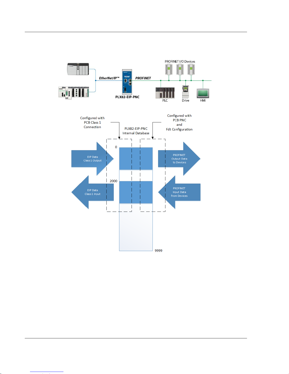
The EtherNet/IP™ to PROFINET Controller gateway provides EtherNet/IP-based
controllers the ability to control up to 36 PROFINET RT devices such as field I/O,
drives, HMIs, controllers, etc.
The PLX82-EIP-PNC gateways are stand-alone DIN-rail mounted units that
provide two Ethernet ports for communications, remote configuration, and
diagnostics. The onboard SD card slot (SD card optional) is used for storing
configuration files that can be used for recovery, transferring the configuration to
another gateway, or general configuration backup.
The gateway supports 248 words of input data and 248 words of output data per
Class 1 connection. The module supports 8 EIP connections and 100 Class 3
EIP commands.
ProSoft Technology, Inc. Page 9 of 154
July 24, 2018
Page 10
Start Here PLX82-EIP-PNC ♦ Communication Gateway
User Manual EtherNet/IP™ Server to PROFINET Controller
The module is configured using ProSoft Configuration Builder (PCB) and ProSoft
fdt Configuration Manager.
ODVA Approved
PROFINET v2 certification with PROFINET Class A compliance
EtherNet/IP and PROFINET certifications ensure that the device is
compatible with their respective network
Field-tested with multiple PROFINET devices from multiple vendors
Remotely view and diagnose EtherNet/IP and PROFINET networks
Embedded EDS AOP provided to allow for seamless integration to Studio
5000 and RSLogix 5000
No ladder programming is required using EtherNet/IP I/O connections
Page 10 of 154 ProSoft Technology, Inc.
July 24, 2018
Page 11

PLX82-EIP-PNC ♦ Communication Gateway Start Here
Qty.
Part Name
Part Number
Part Description
1
EtherNet/IP™
Server to
PROFINET
Controller
PLX82-EIP-PNC
ProSoft communication gateway
1
Screwdriver
HRD250
Small, flat-bladed screwdriver
1
Power Connector
J180
3-wire DC power connector
EtherNet/IP™ Server to PROFINET Controller User Manual
1.2 System Requirements
The PLX82-EIP-PNC module requires the following minimum hardware and
software components:
Rockwell Automation ControlLogix or CompactLogix processor (firmware
version 10 or higher).
Rockwell Automation RSLogix 5000 programming software version 16 or
higher
Rockwell Automation RSLinx® communication software version 2.51 or
higher.
The ProSoft Configuration Builder configuration software for the PLX82-EIP-PNC
gateway requires the following minimum hardware and software components:
Pentium® II 450 MHz minimum. Pentium III 733 MHz (or better)
recommended
128 Mbytes of RAM minimum, 256 Mbytes of RAM recommended
100 Mbytes of free hard disk space (or more based on application
requirements)
256-color VGA graphics adapter, 800 x 600 minimum resolution (True Color
1024 x 768 recommended)
Supported operating systems:
Microsoft Windows 7 (32 bit) (64bit not tested)
Microsoft Windows Vista (not tested)
Microsoft Windows XP Professional with Service Pack 1 or 2
Microsoft Windows 2000 Professional with Service Pack 1, 2, or 3 (not
tested)
Microsoft Windows Server 2003 (not tested)
ProSoft fdt Configuration Manager requires that Microsoft .NET be installed on
the PC or laptop used to configure the gateway.
1.3 Shipping Contents
The following components are included with the PLX82-EIP-PNC.
If any of these components are missing, please contact ProSoft Technology
Technical Support for replacement parts.
ProSoft Technology, Inc. Page 11 of 154
July 24, 2018
Page 12
Start Here PLX82-EIP-PNC ♦ Communication Gateway
User Manual EtherNet/IP™ Server to PROFINET Controller
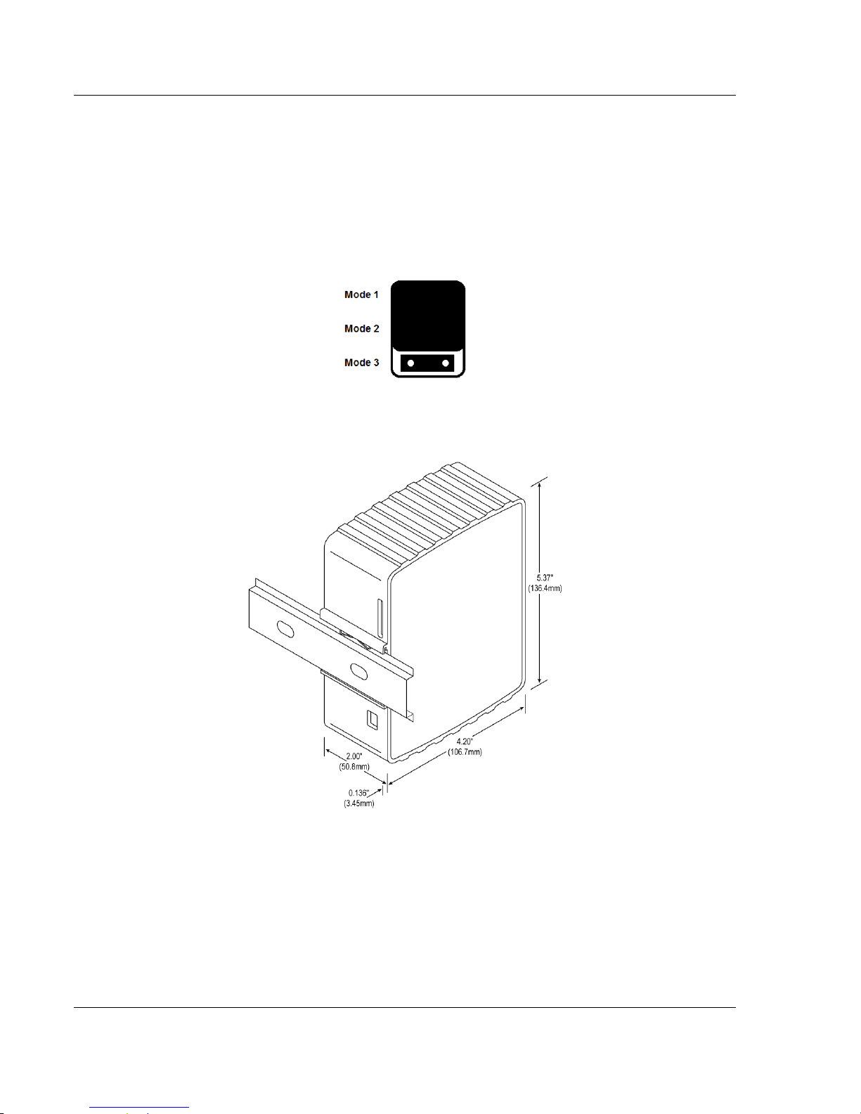
1.4 Setting Jumpers
The jumper settings are located on the back of the PLX82-EIP-PNC. For security
reasons, the Mode 1 and Mode 2 jumpers are not readily accessible. Under
normal conditions, these two jumpers will not be required.
Setup Jumper
Mode 3 is jumpered by default. It is only required for firmware updates.
1.5 Mounting the PLX82-EIP-PNC on a DIN-rail
1 Position the PLX82-EIP-PNC on the DIN-rail B at a slight angle.
2 Hook the lip on the rear of the adapter onto the top of the DIN-rail, and rotate
the adapter onto the rail.
3 Press the adapter down onto the DIN-rail until flush. The locking tab snaps
into position and locks the module to the DIN-rail.
4 If the adapter does not lock in place, use a screwdriver or similar device to
move the locking tab down while pressing the adapter flush onto the DIN-rail
and release the locking tab to lock the adapter in place. If necessary, push up
on the locking tab to lock.
Page 12 of 154 ProSoft Technology, Inc.
July 24, 2018
Page 13
PLX82-EIP-PNC ♦ Communication Gateway Start Here
EtherNet/IP™ Server to PROFINET Controller User Manual
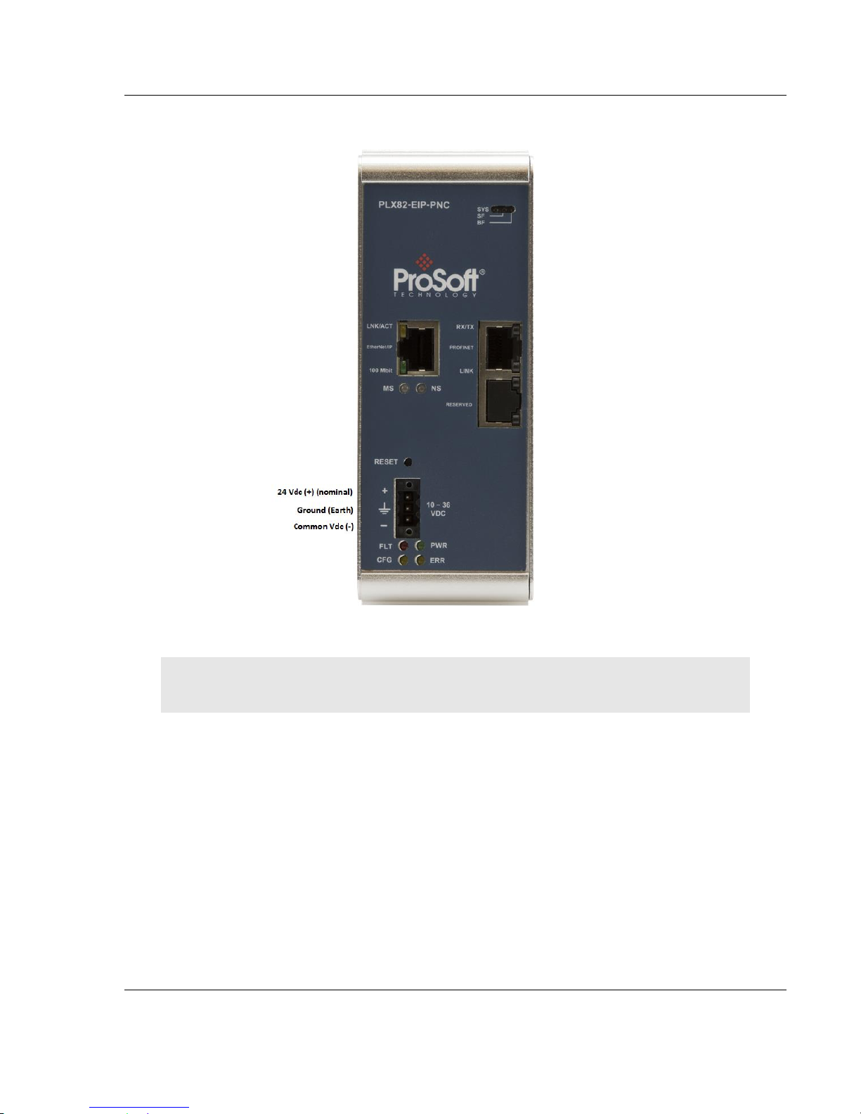
1.6 Connecting Power
Use the J180 Power Connector to connect to the proper signals.
WARNING: Be sure not to reverse polarity when applying power to the PLX82-EIP-PNC. This
causes permanent damage to the internal power distribution circuits.
ProSoft Technology, Inc. Page 13 of 154
July 24, 2018
Page 14

PLX82-EIP-PNC ♦ Communication Gateway
User Manual EtherNet/IP™ Server to PROFINET Controller
Page 14 of 154 ProSoft Technology, Inc.
July 24, 2018
Page 15

PLX82-EIP-PNC ♦ Communication Gateway ProSoft Configuration Builder Software
In This Chapter
Creating a New Project.......................................................................... 16
Setting a Project Name.......................................................................... 17
Setting a Temporary IP Address ........................................................... 18
Ethernet Configuration .......................................................................... 22
Saving the Project ................................................................................. 23
Downloading the Configuration File to the PLX82-EIP-PNC ................. 24
Uploading a Configuration from the PLX82-EIP-PNC ........................... 25
Exporting a Project ................................................................................ 26
Writing the Project to Compact Flash .................................................... 27
EtherNet/IP™ Server to PROFINET Controller User Manual
2 ProSoft Configuration Builder Software
ProSoft Configuration Builder (PCB) and ProSoft fdt Configuration Manager is
used to configure the PLX82-EIP-PNC. You can find both software files at
www.prosoft-technology.com.
Important Note: Microsoft .NET must be installed on your PC or laptop used to perform
configuration tasks. This is required for ProSoft fdt Configuration Manager to install and run.
Note: To use the ProSoft Configuration Builder under the Windows 7 OS, you must be sure to
install it using the Run as Administrator option. To find this option, right-click the Setup.exe
program icon, and then click RUN AS ADMINISTRATOR on the context menu. You must install using
this option even if you are already logged in as an Administrator on your network or personal
computer (PC). Using the Run as Administrator option allows the installation program to create
folders and files on your PC with proper permissions and security. If you do not use the Run as
Administrator option, the ProSoft Configuration Builder may appear to install correctly, but you will
receive multiple file access errors whenever the ProSoft Configuration Builder is running, especially
when changing configuration screens. If this happens, you must completely uninstall the ProSoft
Configuration Builder and then re-install using the Run as Administrator option to eliminate the
errors.
ProSoft Technology, Inc. Page 15 of 154
July 24, 2018
Page 16
ProSoft Configuration Builder Software PLX82-EIP-PNC ♦ Communication Gateway
User Manual EtherNet/IP™ Server to PROFINET Controller
2.1 Creating a New Project
1 From your PC, click START > PROSOFT TECHNOLOGY > PROSOFT
CONFIGURATION BUILDER.
2 Click FILE > NEW. The application prompts for a Module Type.
Page 16 of 154 ProSoft Technology, Inc.
July 24, 2018
Page 17

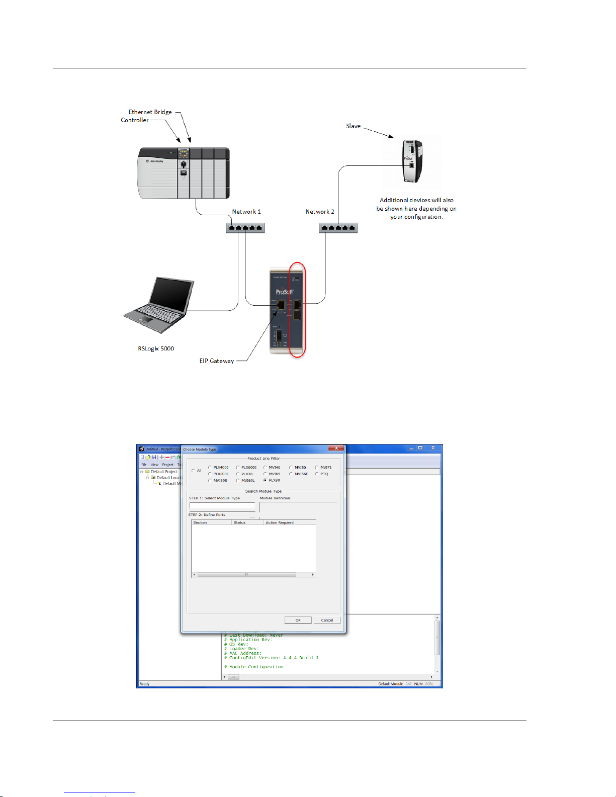
PLX82-EIP-PNC ♦ Communication Gateway ProSoft Configuration Builder Software
EtherNet/IP™ Server to PROFINET Controller User Manual
3 Select the PLX80 radio button and then select PLX82-EIP-PNC.
4 Click OK. The PLX82-EIP-PNC is now added to ProSoft Configuration
builder.
ProSoft Technology, Inc. Page 17 of 154
July 24, 2018
Page 18
ProSoft Configuration Builder Software PLX82-EIP-PNC ♦ Communication Gateway
User Manual EtherNet/IP™ Server to PROFINET Controller
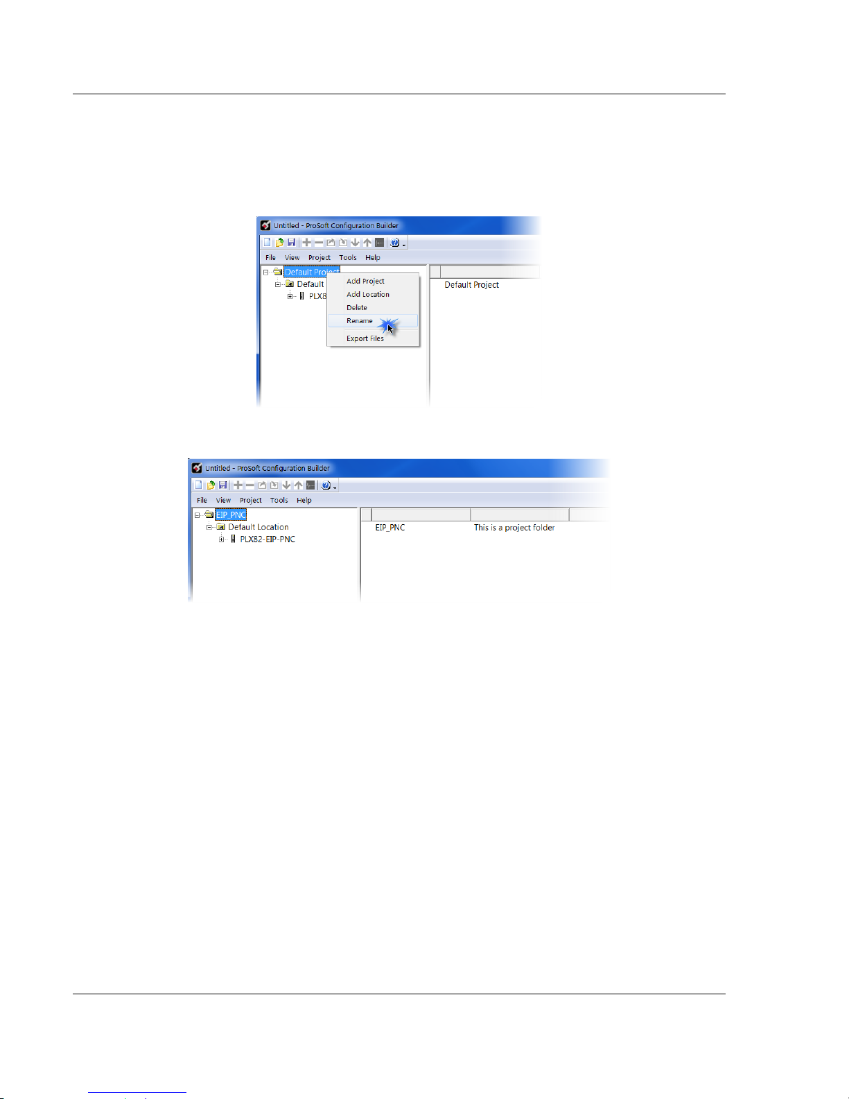
2.2 Setting a Project Name
The project name is initially set to "Default Location".
1 Right click on the DEFAULT LOCATION icon and select RENAME.
2 Type in a name for your project and press ENTER.
Page 18 of 154 ProSoft Technology, Inc.
July 24, 2018
Page 19
PLX82-EIP-PNC ♦ Communication Gateway ProSoft Configuration Builder Software
EtherNet/IP™ Server to PROFINET Controller User Manual
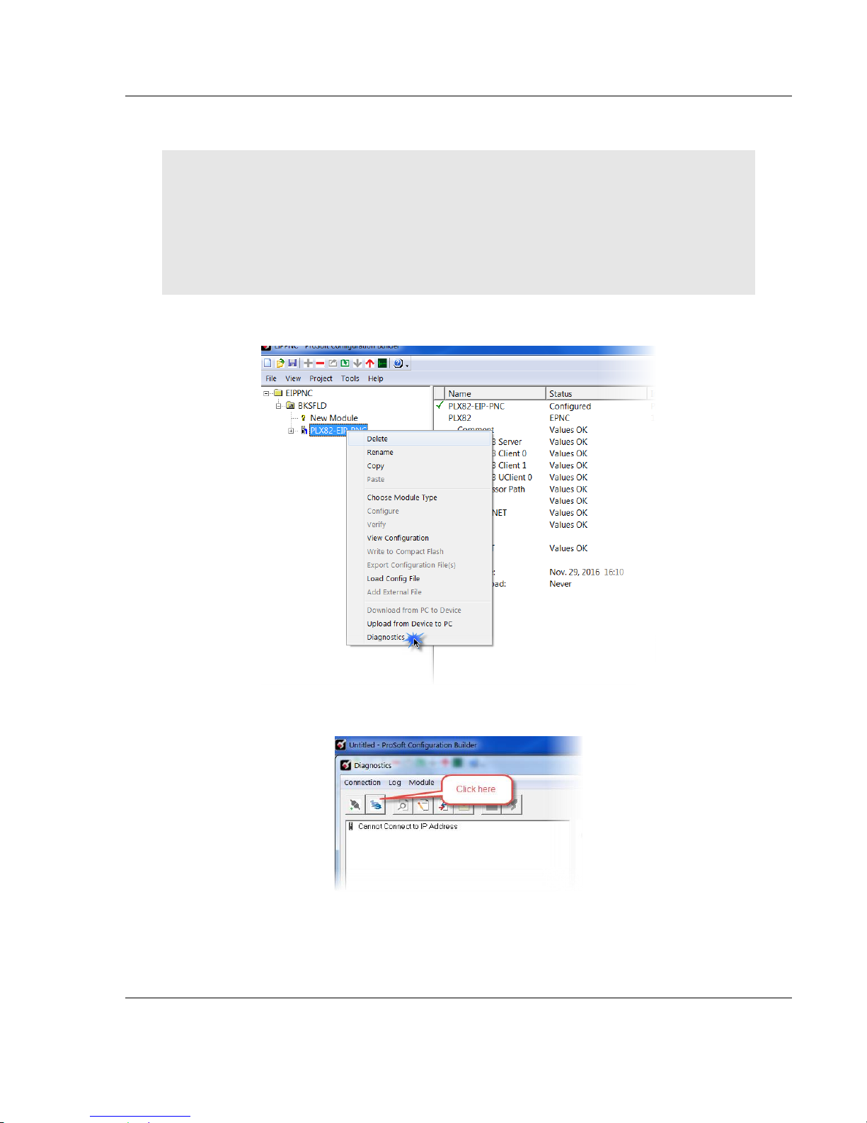
2.3 Setting a Temporary IP Address
Important: ProSoft Discovery Service (PDS) is a built-in utility within PCB. It locates the PLX82EIP-PNC through UDP broadcast messages. These messages may be blocked by routers or layer
3 switches. In that case, PDS is unable to locate the PLX82-EIP-PNC.
To use PDS, arrange the Ethernet connection so that there is no router or layer 3 switch between
the computer and the PLX82-EIP-PNC, or reconfigure the router or layer 3 switch to allow the
routing of the UDP broadcast messages.
1 Right-click the PLX82-EIP-PNC icon and select DIAGNOSTICS.
2 When the Diagnostics dialog opens, click on the SETUP CONNECTION icon.
ProSoft Technology, Inc. Page 19 of 154
July 24, 2018
Page 20

ProSoft Configuration Builder Software PLX82-EIP-PNC ♦ Communication Gateway
User Manual EtherNet/IP™ Server to PROFINET Controller
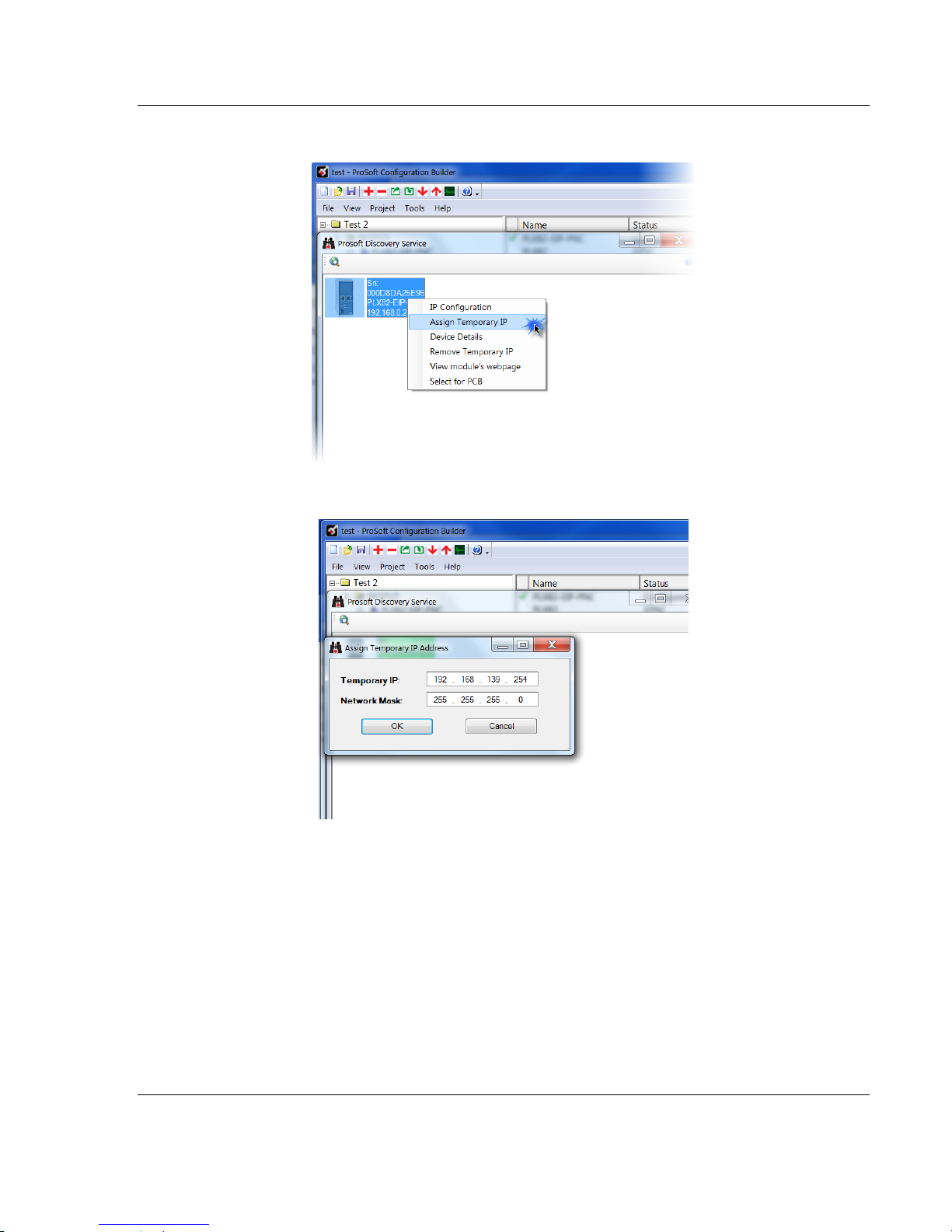
3 When the Connection Setup dialog opens, click the BROWSE DEVICES button
to locate your device.
4 This launches Prosoft Discovery Service, which displays the ProSoft modules
that have been detected on the network
Page 20 of 154 ProSoft Technology, Inc.
July 24, 2018
Page 21
PLX82-EIP-PNC ♦ Communication Gateway ProSoft Configuration Builder Software
EtherNet/IP™ Server to PROFINET Controller User Manual
5 Right-click the module, and then click ASSIGN TEMPORARY IP.
6 The module’s default IP address is 192.168.0.250.
7 Enter an unused IP within your subnet, and then click OK.
ProSoft Technology, Inc. Page 21 of 154
July 24, 2018
Page 22
ProSoft Configuration Builder Software PLX82-EIP-PNC ♦ Communication Gateway
User Manual EtherNet/IP™ Server to PROFINET Controller
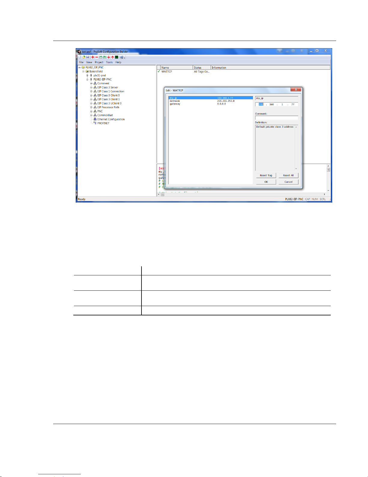
2.4 Ethernet Configuration
This is used to provide address information for the gateway; in this case, the EIP
driver. This is unique address information for the PLX82-EIP-PNC's EIP driver
and diagnostic interface. The default is initially set to 192.168.0.250.
Page 22 of 154 ProSoft Technology, Inc.
July 24, 2018
Page 23
PLX82-EIP-PNC ♦ Communication Gateway ProSoft Configuration Builder Software
Parameter
Description
my_ip
This is the default address assigned to the EIP side of the gateway. Change
this to the address that suites your network configuration.
netmask
This is the default network mask. Update this to the appropriate network
mask.
gateway
This is the IP address for gateway that you want to use.
EtherNet/IP™ Server to PROFINET Controller User Manual
1 Select my_ip and enter the IP address of the EIP device in the gateway.
2 Select netmask and enter the network mask.
3 If using a gateway/router, select gateway and enter the IP address of the
network gateway (router). If you are not using a gateway/router, enter 0.0.0.0
in this field.
4 Click OK when done.
2.5 Saving the Project
The PCB project must be saved when you move from PCB to ProSoft fdt
Configuration Manager if you have not previously saved the project while in PCB.
1 Navigate to FILE > SAVE AS.
2 Select the appropriate directory and filename name of your ProSoft Project
File (PPF).
3 Click SAVE.
ProSoft Technology, Inc. Page 23 of 154
July 24, 2018
Page 24
ProSoft Configuration Builder Software PLX82-EIP-PNC ♦ Communication Gateway
User Manual EtherNet/IP™ Server to PROFINET Controller
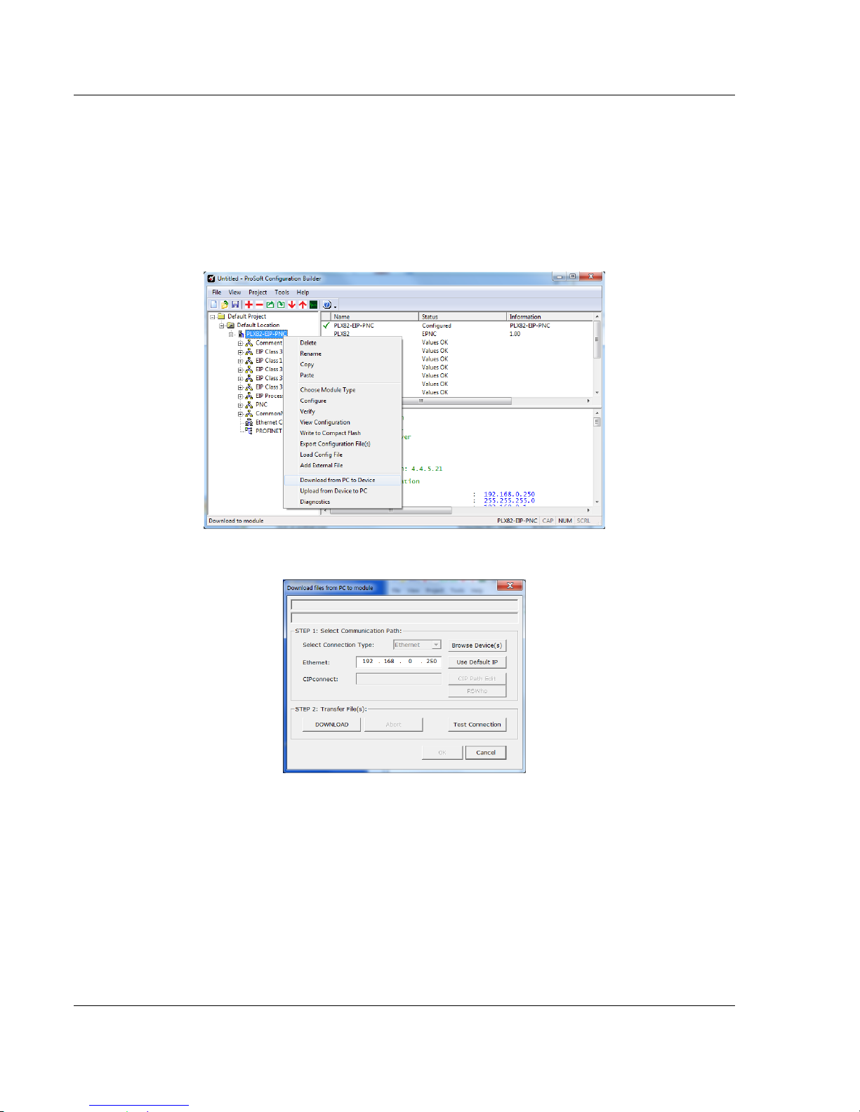
2.6 Downloading the Configuration File to the PLX82-EIP-PNC
After you have created the project in the ProSoft Configuration Builder and
ProSoft fdt Configuration Manager software, you are ready to download it to the
PLX82-EIP-PNC.
1 From PCB, right-click on the PLX82-EIP-PNC icon and select DOWNLOAD
FROM PC TO DEVICE.
2 The Download files from PC to module dialog box opens:
3 Click TEST CONNECTION.
If the PLX82-EIP-PNC's IP address matches the address in the Configuration
Manager, and the software displays the following message: "Successfully
connected."
If the PLX82-EIP-PNC’s IP address does not match what was entered in
ProSoft Configuration Builder, then the software displays an error message:
"Error: Connecting to Module. Please check your IP Address."
4 Click DOWNLOAD to download the project to the PLX82-EIP-PNC.
Page 24 of 154 ProSoft Technology, Inc.
July 24, 2018
Page 25
PLX82-EIP-PNC ♦ Communication Gateway ProSoft Configuration Builder Software
EtherNet/IP™ Server to PROFINET Controller User Manual
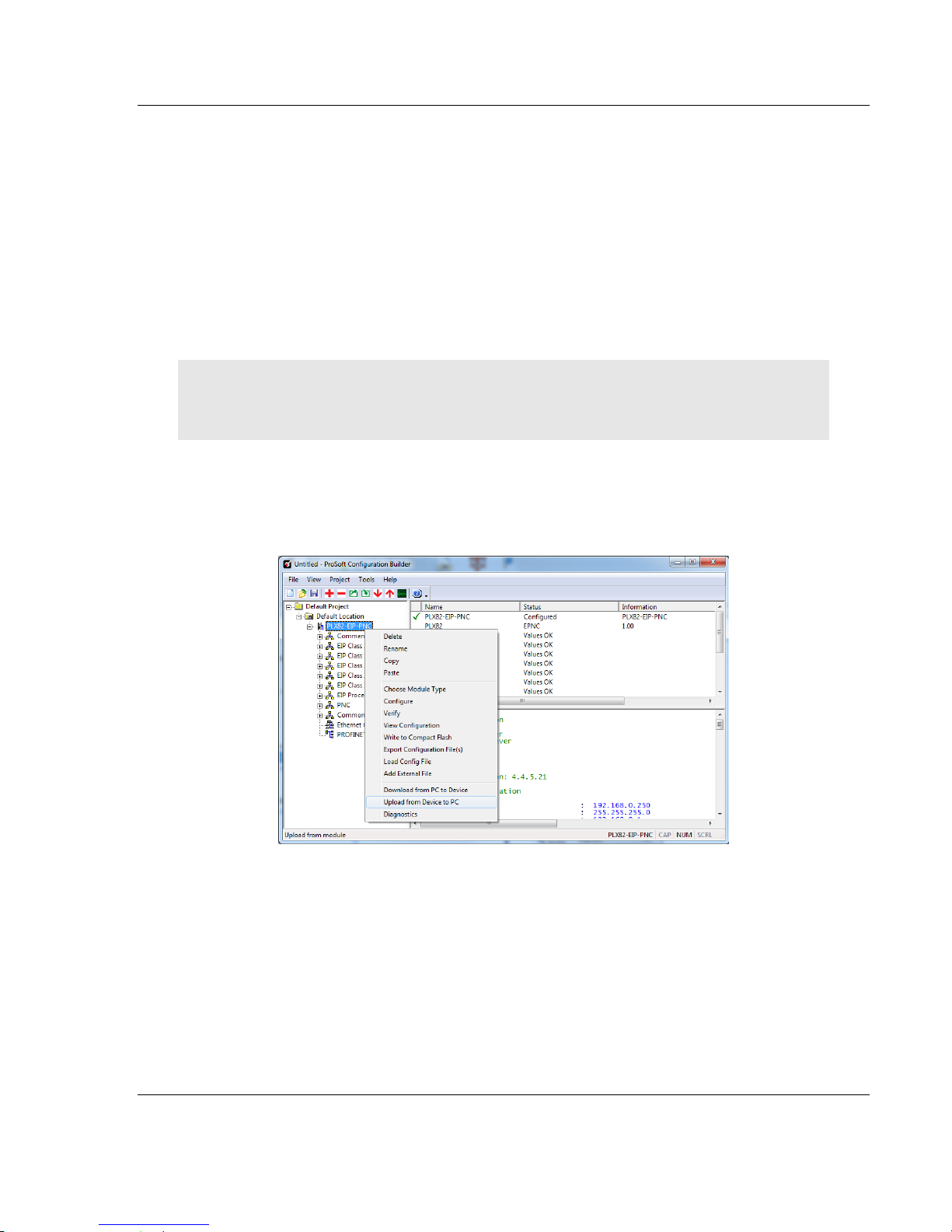
2.7 Uploading a Configuration from the PLX82-EIP-PNC
Use this feature to retrieve the configuration from the PLX82-EIP-PNC. Not only
does it retrieve the configuration, but is also retrieves all related files used in
creating that configuration. There are several reasons that you might use this
feature:
You want to modify the configuration, but do not have access to the original
configuration files.
You want to copy a configuration from one PLX82-EIP-PNC to another
PLX82-EIP-PNC.
You want to back up the configuration for safety.
Warning: This function replaces the current configuration in the ProSoft Configuration Builder with
the one from the PLX82-EIP-PNC. Make sure you save the current configuration before uploading
the configuration from the PLX82-EIP-PNC.
1 Optional: Create a new project in the ProSoft Configuration Builder by
choosing FILE > NEW.
2 Right-click the PLX82-EIP-PNC icon and choose UPLOAD FROM DEVICE TO
PC.
ProSoft Technology, Inc. Page 25 of 154
July 24, 2018
Page 26
ProSoft Configuration Builder Software PLX82-EIP-PNC ♦ Communication Gateway
User Manual EtherNet/IP™ Server to PROFINET Controller
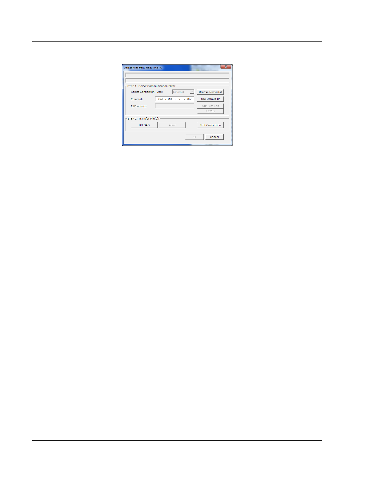
3 The Upload files from Module to PC dialog box opens:
4 Select the Connection Type. If you don't know the IP address of the module
that contains the configuration that you want, you can browse devices using
the BROWSE DEVICE(S) button. This launches the ProSoft Discovery Service
application.
5 Enter the IP address of the PLX82-EIP-PNC. All PLX82-EIP-PNC's are
shipped with a default IP address 192.168.0.250. Click the USE DEFAULT IP
button to use the default address.
6 Use the TEST CONNECTION button to ensure that the connection is good.
7 Click the UPLOAD button to start the upload.
8 When the upload is complete, the configuration is displayed in PCB. You can
edit or save it on the PC.
2.8 Exporting a Project
You can export a PCB file that was created on your PC. This allows someone on
a different PC to import your configuration file and have all the files that are part
of your project. If you need assistance from ProSoft Technology Technical
Support, they will need your exported files.
1 In the ProSoft Configuration Builder choose PROJECT > MODULE > EXPORT
CONFIGURATION FILES.
2 In the Save As dialog box, navigate to the correct directory and save the
configuration file.
Page 26 of 154 ProSoft Technology, Inc.
July 24, 2018
Page 27
PLX82-EIP-PNC ♦ Communication Gateway ProSoft Configuration Builder Software
EtherNet/IP™ Server to PROFINET Controller User Manual
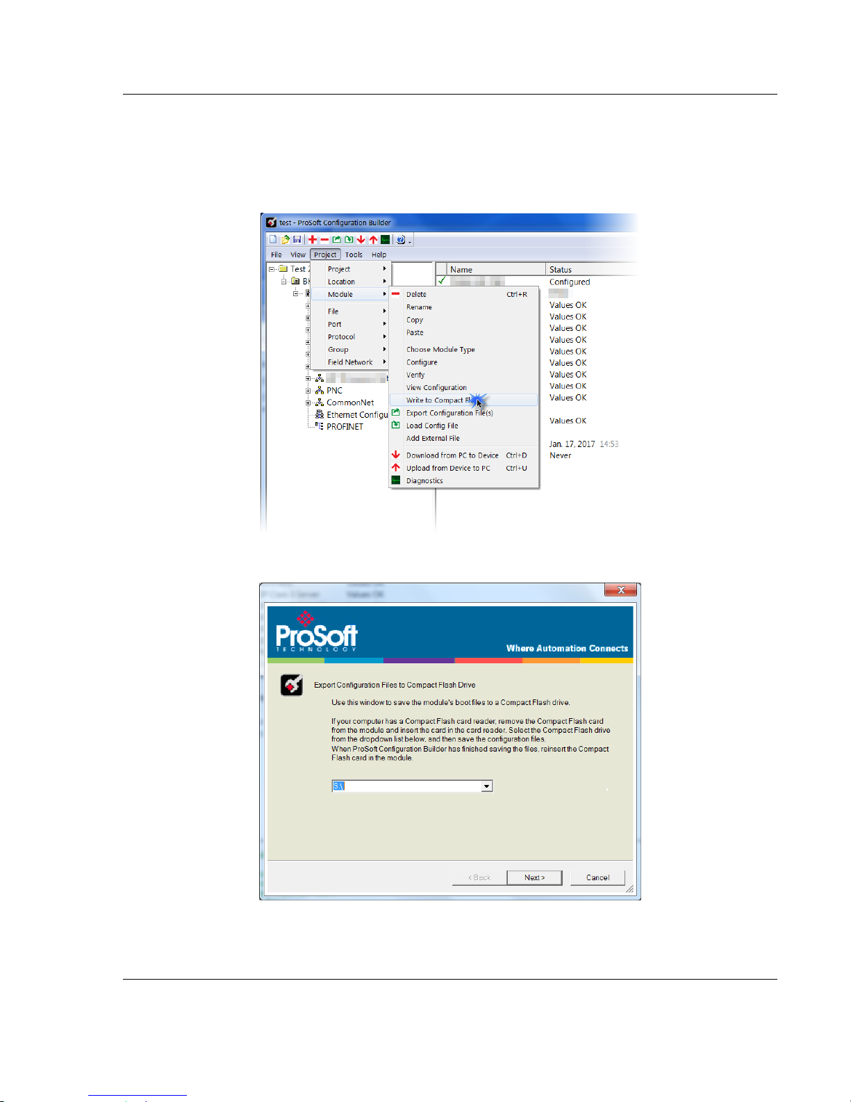
2.9 Writing the Project to Compact Flash
This procedure describes how to save a project from a PC to a Compact Flash
drive.
1 From PCB, navigate to PROJECT > MODULE > WRITE TO COMPACT FLASH.
2 Choose the appropriate drive, then click NEXT.
3 Follow the on-screen instructions and click FINISH when complete.
ProSoft Technology, Inc. Page 27 of 154
July 24, 2018
Page 28

ProSoft Configuration Builder Software PLX82-EIP-PNC ♦ Communication Gateway
User Manual EtherNet/IP™ Server to PROFINET Controller
Page 28 of 154 ProSoft Technology, Inc.
July 24, 2018
Page 29
PLX82-EIP-PNC ♦ Communication Gateway Configuring the EtherNet/IP Driver
In This Chapter
RSLogix 5000 ........................................................................................ 30
Adding an Ethernet Bridge .................................................................... 31
Adding the PLX82-EIP-PNC .................................................................. 33
Importing the Ladder Rung .................................................................... 36
Downloading the RSLogix 5000 Project to the Processor ..................... 38
EIP Class 3 Server Connection ............................................................. 39
EIP Class 1 Connection......................................................................... 40
EIP Class 3 Client/UClient [x] Connection ............................................. 41
Configuring the EIP Processor Path ...................................................... 49
EtherNet/IP™ Server to PROFINET Controller User Manual
3 Configuring the EtherNet/IP Driver
ProSoft Technology, Inc. Page 29 of 154
July 24, 2018
Page 30

Configuring the EtherNet/IP Driver PLX82-EIP-PNC ♦ Communication Gateway
User Manual EtherNet/IP™ Server to PROFINET Controller
3.1 RSLogix 5000
If you want to add the PLX82-EIP-PNC gateway to an existing project, skip to
Adding an Ethernet Bridge (page 31).
To create a new project...
1 In RSLogix 5000, choose FILE > NEW.
2 Select your PLC (a ControlLogix, or CompactLogix PLC).
3 Select REVISION 16 or newer.
4 Enter a name for your controller, such as MY_CONTROLLER.
5 Select your chassis type and click OK.
Page 30 of 154 ProSoft Technology, Inc.
July 24, 2018
Page 31

PLX82-EIP-PNC ♦ Communication Gateway Configuring the EtherNet/IP Driver
EtherNet/IP™ Server to PROFINET Controller User Manual
3.2 Adding an Ethernet Bridge
1 Expand the I/O CONFIGURATION folder in the Project tree. Right-click the
appropriate communications bus and choose NEW MODULE.
2 This opens the Select Module Type dialog box.
ProSoft Technology, Inc. Page 31 of 154
July 24, 2018
Page 32

Configuring the EtherNet/IP Driver PLX82-EIP-PNC ♦ Communication Gateway
User Manual EtherNet/IP™ Server to PROFINET Controller
3 For this example, click the 1756-ENBT ETHERNET BRIDGE and then click
CREATE.
4 Enter the name, revision, and IP address for the 1756-ENBT and then click
OK.
Page 32 of 154 ProSoft Technology, Inc.
July 24, 2018
Page 33

PLX82-EIP-PNC ♦ Communication Gateway Configuring the EtherNet/IP Driver
EtherNet/IP™ Server to PROFINET Controller User Manual
3.3 Adding the PLX82-EIP-PNC
1 In RSLogix 5000, under the 1756-ENBT icon, right-click ETHERNET and then
choose NEW MODULE.
2 Select the GENERIC ETHERNET/IP CIP BRIDGE and then click CREATE.
ProSoft Technology, Inc. Page 33 of 154
July 24, 2018
Page 34

Configuring the EtherNet/IP Driver PLX82-EIP-PNC ♦ Communication Gateway
User Manual EtherNet/IP™ Server to PROFINET Controller
3 Enter the name and IP address for the gateway and then click OK.
4 Under the gateway (PLX82_EIP_PNC in this example), right-click CIP BUS
and then choose NEW MODULE.
5 Click the GENERIC CIP MODULE and then click CREATE.
Page 34 of 154 ProSoft Technology, Inc.
July 24, 2018
Page 35

PLX82-EIP-PNC ♦ Communication Gateway Configuring the EtherNet/IP Driver
EtherNet/IP™ Server to PROFINET Controller User Manual
6 Add a Class 1 connection (enter the name and configuration parameters).
Enter the Name, select DATA-INT for Comm Format, and enter the
Connection Parameters as shown below. Click OK.
7 Right-click the new connection and then choose PROPERTIES.
8 On the Connection tab, enter the Requested Packet Interval (RPI) time and
then click OK.
ProSoft Technology, Inc. Page 35 of 154
July 24, 2018
Page 36

Configuring the EtherNet/IP Driver PLX82-EIP-PNC ♦ Communication Gateway
User Manual EtherNet/IP™ Server to PROFINET Controller
3.4 Importing the Ladder Rung
1 Download the .L5X file from the PLX82-EIP-PNC product page at
www.prosoft-technology.com.
2 Open the Main Routine.
3 Right-click on an existing rung and select IMPORT RUNGS.
4 At the Input Rungs dialog, locate the directory that contains the Add On rung.
5 Click IMPORT.
Page 36 of 154 ProSoft Technology, Inc.
July 24, 2018
Page 37

PLX82-EIP-PNC ♦ Communication Gateway Configuring the EtherNet/IP Driver
EtherNet/IP™ Server to PROFINET Controller User Manual
6 In the Import Configuration dialog box, make sure the Operation is set to
CREATE, and then click OK.
7 When the import completes, the Add-On Instruction appears under Add-On
Instructions in the window.
ProSoft Technology, Inc. Page 37 of 154
July 24, 2018
Page 38

Configuring the EtherNet/IP Driver PLX82-EIP-PNC ♦ Communication Gateway
User Manual EtherNet/IP™ Server to PROFINET Controller
3.5 Downloading the RSLogix 5000 Project to the Processor
1 Save, and then download the project to the processor.
2 A yellow triangle in RSLogix 5000 means an error on connection. Check that
the OUTPUT size and INPUT size for the Class 1 connection in the gateway
configuration matches and the COMM FORMAT is INT. Try increasing the
REQUESTED PACKET INTERVAL time of module if the error persists.
3 Check the PLX82-EIP-PNC's IP address. This is located in the bottom left of
the Diagnostics page.
4 If errors persist, download the configuration again to make sure that the
module configuration matches the configured RSLogix 5000 program.
5 For additional troubleshooting, use the ProSoft Configuration Builder. Click on
PROJECT > MODULE > DIAGNOSTICS.
Class 1 displays the connection RPI time of processor and the IP address of
the module. The open connection count starts at 1 and increments if the
connection to the processor is interrupted or there is a connection timeout.
State, open connection, and connection timeout are controlled by the code.
You can change the RPI and Ethernet IP in the ladder configuration in
RSLogix 5000 (right-click CONNECTION1 and choose PROPERTIES).
Page 38 of 154 ProSoft Technology, Inc.
July 24, 2018
Page 39

PLX82-EIP-PNC ♦ Communication Gateway Configuring the EtherNet/IP Driver
EtherNet/IP™ Server to PROFINET Controller User Manual
3.6 EIP Class 3 Server Connection
Use the EIP Class 3 Server connection in ProSoft Configuration Builder when the
gateway is acting as a server (slave) device responding to message instructions
initiated from a client (Controller) device such as an HMI, DCS, PLC, or PAC.
1 Within ProSoft Configuration Builder, click the [+] next to the gateway, then
click the [+] next to EIP Class 3 Server.
2 Double-click the second EIP CLASS 3 SERVER to display the Edit - EIP Class
3 Server dialog box.
3 Select the Server File Size (100 or 1000).
o For a value of 100, the registers are from N10:0 to N10:99.
o For a value of 1000, the valid registers are from N10:0 to N10:999.
ProSoft Technology, Inc. Page 39 of 154
July 24, 2018
Page 40

Configuring the EtherNet/IP Driver PLX82-EIP-PNC ♦ Communication Gateway
User Manual EtherNet/IP™ Server to PROFINET Controller
3.7 EIP Class 1 Connection
The EIP Class 1 connection is used with the gateway and acts as an EtherNet/IP
adapter transferring data to and from a PLC using a direct I/O connection. Direct
I/O connections can be used to transfer large amounts of data quickly.
The EIP driver can handle up to eight I/O connections, each with 248 words of
input data and 248 words of output data. Rockwell Automation customers
running RSLogix 5000 v2.0 or higher can take advantage of premier integration
with an Add-on profile.
After you create the PLX82-EIP-PNC in RSLogix 5000, you must configure
gateway connections.
1 In ProSoft Configuration Builder, click the [+] next to the gateway, and then
click the [+] next to EIP Class 1 Connection [x].
2 Double-click the EIP CLASS 1 CONNECTION [X] to display the Edit - EIP Class
1 Connection [x] dialog box.
3 In the dialog box, enter a value for each parameter.
Page 40 of 154 ProSoft Technology, Inc.
July 24, 2018
Page 41

PLX82-EIP-PNC ♦ Communication Gateway Configuring the EtherNet/IP Driver
Parameter
Value
Description
Input Data Address
0 to 9999
This parameter specifies the starting address within the
gateway's virtual database for data transferred from the PLC to
the module.
Input size
0 to 248
This parameter specifies the number of integers being
transferred to the PLC's input image (248 integers max).
Output data address
0 to 9999
This parameter specifies the starting address within the
gateway's virtual database for data transferred from the
gateway to the PLC.
Output size
0 to 248
This parameter specifies the number of integers being
transferred to the PLC's output image (248 integers max).
EtherNet/IP™ Server to PROFINET Controller User Manual
Create entries for up to 8 connections by following the same steps.
3.8 EIP Class 3 Client/UClient [x] Connection
EIP Class 3 Client [x] connections are used when the gateway is acting as a
client/controller initiating message instructions to the server/slave devices. The
EIP driver supports three connected clients. Typical applications include SCADA
systems, PLC and SLC communication.
The EIP driver supports one unconnected client connection. Unconnected
messaging is a type of EtherNet/IP explicit messaging that uses TCP/IP
implementation. Certain devices, such as the AB Power Monitor 3000 series B,
support unconnected messaging. Check your device documentation for further
information about its EtherNet/IP implementation.
3.8.1 EIP Class 3 Client/UClient [x]
1 In ProSoft Configuration Builder, click the [+] next to the gateway, then click
the [+] next to EIP Class 3 Client [x] or EIP Class 3 UClient [x].
2 Double-click the second EIP Class 3 Client [x] to display the Edit - EIP Class
3 Client [x] dialog box.
3 Click a parameter to change it's value.
ProSoft Technology, Inc. Page 41 of 154
July 24, 2018
Page 42

Configuring the EtherNet/IP Driver PLX82-EIP-PNC ♦ Communication Gateway
Parameter
Value
Description
Minimum Command
Delay
0 to 65535
milliseconds
Specifies the number of milliseconds to wait between the initial
issuances of a command. This parameter can be used to delay
all commands sent to servers to avoid "flooding" commands on
the network. This parameter does not affect retries of a
command as they will be issued when a failure is recognized.
Response Timeout
0 to 65535
milliseconds
Specifies the amount of time in milliseconds that a client will wait
before re-transmitting a command if no response is received
from the addressed server. The value depends on the type of
communication network used, and the expected response time
of the slowest device connected to the network.
Retry Count
0 to 10
Specifies the number of times a command will be retried if it fails.
User Manual EtherNet/IP™ Server to PROFINET Controller
The following table specifies the configuration for the EIP client (Controller)
device on the network port:
3.8.2 EIP Class 3 Client/UClient [x] Commands
There is a separate command list for each of the different message types
supported by the protocol. Each list is processed from top to bottom, one
after the other, until all specified commands are completed, and then the
polling process begins all over again.
This section defines the EtherNet/IP commands to be issued from the
gateway to server devices on the network. These commands can be used for
data collection and/or control of devices on the TCP/IP network.
In order to interface the virtual database with Rockwell Automation
Programmable Automation controllers (PACs), Programmable Logic
Controllers (PLCs), or other EtherNet/IP server devices, you must construct a
command list using the command list parameters for each message type.
To add Class 3 Client/UClient [x] commands...
1 In ProSoft Configuration Builder, click the [+] next to the gateway, the click
the [+] next to EIP Class 3 Client [x] or EIP Class 3 UClient [x].
2 Double-click the desired command type to display the Edit - EIP Class 3
Client [x] Commands or Edit - EIP Class 3 UClient Commands dialog box.
3 Click ADD ROW to add a new command.
4 Click EDIT ROW or double-click the row to display the Edit dialog box where
you configure the command.
Page 42 of 154 ProSoft Technology, Inc.
July 24, 2018
Page 43

PLX82-EIP-PNC ♦ Communication Gateway Configuring the EtherNet/IP Driver
Parameter
Value
Description
Enable
Enable
Disable
Conditional Write
Specifies if the command should be executed and under what conditions.
Enable - The command is execute each scan of the command list.
Disable - The command is disabled and will not be executed.
Conditional Write - The command executes only if the internal data
associated with the command changes.
Internal Address
0 to 9999
Specifies the database address in the module's internal database to be
associated with the command. If the command is a read function, the data
received in the response message is placed at the specified location. If the
command is a write function, data used in the command is sourced from a
specified data area.
Poll Interval
0 to 65535
Specifies the minimum interval to execute continuous commands. The
parameter is entered in 1/10 of a second. If a value of 100 is entered for a
command the command executes no more frequently that every 10 seconds.
Reg Count
1 to 125
Specifies the number of data points to be read from or written to the target
audience.
Swap Code
None
Word Swap
Word and Byte Swap
Byte Swap
Specifies if the data from the server is to be ordered differently than it was
received. This parameter is typically used when dealing with floating-point or
other multi-register values.
None - No change is made (abcd)
Word Swap - The words are swapped (cdab)
Word and Byte Swap - The words and bytes are swapped (dcba)
Byte Swap - The bytes are swapped (badc).
IP Address
xxx.xxx.xxx.xxx
Specifies the IP address of the target device to be addressed by this
command.
Slot
-1
Use a value of -1 when interfacing to an SLC 5/05. These devices do not have
a slot parameter. When addressing a processor in a ControlLogix or
CompactLogix rack, the slot number corresponds to the slot in the rack
containing the controller being addressed.
Func Code
501
509
Specifies the function code to be used in the command.
501 - Protected Typed Read
509 - Protected Typed Write
File Type
Binary
Counter
Timer
Control
Integer
Float
ASCII
String
Status
Specifies the file type to be associated with the command.
File Number
-1
Specifies the PLC-5 file number to be associated with the command. If a value
of -1 is entered for the parameter, the field will not be used in the command,
and the default file will be used.
Element Number
Specifies the element in the file where the command will start.
Comment
This field can be used to give a 32-character comment to the command.
EtherNet/IP™ Server to PROFINET Controller User Manual
Class 3 Client/UClient [x] Commands SLC500 2 Address Fields
ProSoft Technology, Inc. Page 43 of 154
July 24, 2018
Page 44

Configuring the EtherNet/IP Driver PLX82-EIP-PNC ♦ Communication Gateway
Parameter
Value
Description
Enable
Enable
Disable
Conditional Write
Specifies if the command should be executed and under what conditions.
Enable - The command is execute each scan of the command list.
Disable - The command is disabled and will not be executed.
Conditional Write - The command executes only if the internal data associated
with the command changes.
Internal Address
0 to 9999
Specifies the database address in the module's internal database to be associated
with the command. If the command is a read function, the data received in the
response message is placed at the specified location. If the command is a write
function, data used in the command is sourced from a specified data area.
Poll Interval
0 to 65535
Specifies the minimum interval to execute continuous commands. The parameter is
entered in 1/10 of a second. If a value of 100 is entered for a command the
command executes no more frequently that every 10 seconds.
Reg Count
1 to 125
Specifies the number of data points to be read from or written to the target device.
Swap Code
None
Word Swap
Word and Byte Swap
Byte Swap
Specifies if the data from the server is to be ordered differently than it was received.
This parameter is typically used when dealing with floating-point or other multiregister values.
None - No change is made (abcd)
Word Swap - The words are swapped (cdab)
Word and Byte Swap - The words and bytes are swapped (dcba)
Byte Swap - The bytes are swapped (badc).
IP Address
xxx.xxx.xxx.xxx
Specifies the IP address of the target device to be addressed by this command.
Slot
-1
Use a value of -1 when interfacing to an SLC 5/05. These devices do not have a
slot parameter. When addressing a processor in a ControlLogix or CompactLogix
rack, the slot number corresponds to the slot in the rack containing the controller
being addressed.
Func Code
502
510
511
Specifies the function code to be used in the command.
502 - Protected Typed Read
510 - Protected Typed Write
511 - Protect Typed Write w/Mask
File Type
Binary
Counter
Timer
Control
Integer
Float
ASCII
String
Status
Specifies the file type to be associated with the command.
File Number
-1
Specifies the PLC-5 file number to be associated with the command. If a value of -1
is entered for the parameter, the field will not be used in the command, and the
default file will be used.
Element Number
Specifies the element in the file where the command will start.
Sub-Element
Specifies the sub-element to be used with the command. Refer to the AB
documentation for a list of valid sub-element codes.
Comment
This field can be used to give a 32-character comment to the command.
User Manual EtherNet/IP™ Server to PROFINET Controller
Class 3 Client/UClient [x] Commands SLC500 3 Address Fields
Page 44 of 154 ProSoft Technology, Inc.
July 24, 2018
Page 45

PLX82-EIP-PNC ♦ Communication Gateway Configuring the EtherNet/IP Driver
Parameter
Value
Description
Enable
Enable
Disable
Conditional Write
Specifies if the command should be executed and under what conditions.
Enable - The command is executed each scan of the command list.
Disable - The command is disabled and will not be executed.
Conditional Write - The command executes only if the internal data associated
with the command changes.
Internal Address
0 to 9999
Specifies the database address in the module's internal database to be associated
with the command. If the command is a read function, the data received in the
response message is placed at the specified location. If the command is a write
function, data used in the command is sourced from a specified data area.
Poll Interval
0 to 65535
Specifies the minimum interval to execute continuous commands. The parameter is
entered in 1/10 of a second. If a value of 100 is entered for a command the
command executes no more frequently that every 10 seconds.
Reg Count
1 to 125
Specifies the number of data points to be read from or written to the target device.
Swap Code
None
Word Swap
Word and Byte Swap
Byte Swap
Specifies if the data from the server is to be ordered differently than it was received.
This parameter is typically used when dealing with floating-point or other multiregister values.
None - No change is made (abcd)
Word Swap - The words are swapped (cdab)
Word and Byte Swap - The words and bytes are swapped (dcba)
Byte Swap - The bytes are swapped (badc).
IP Address
xxx.xxx.xxx.xxx
Specifies the IP address of the target device to be addressed by this command.
Slot
-1
Use a value of -1 when interfacing to an SLC 5/05. These devices do not have a
slot parameter. When addressing a processor in a ControlLogix or CompactLogix
rack, the slot number corresponds to the slot in the rack containing the controller
being addressed.
Func Code
100
101
102
Specifies the function code to be used in the command.
100 - Word Range Write
101 - Word Range Read
102 - Read-Modify-Write
File Type
Binary
Counter
Timer
Control
Integer
Float
ASCII
String
Status
Specifies the file type to be associated with the command.
File Number
-1
Specifies the PLC-5 file number to be associated with the command. If a value of -1
is entered for the parameter, the field will not be used in the command, and the
default file will be used.
Element Number
Specifies the element in the file where the command will start.
Sub-Element
Specifies the sub-element to be used with the command. Refer to the AB
documentation for a list of valid sub-element codes.
Comment
This field can be used to give a 32-character comment to the command.
EtherNet/IP™ Server to PROFINET Controller User Manual
Class 3 Client/UClient [x] Commands PLC5 Binary
ProSoft Technology, Inc. Page 45 of 154
July 24, 2018
Page 46

Configuring the EtherNet/IP Driver PLX82-EIP-PNC ♦ Communication Gateway
Parameter
Value
Description
Enable
Enable
Disable
Conditional Write
Specifies if the command should be executed and under what conditions.
ENABLE - The Command is executed each scan of the command list
DISABLE- The command is disabled and will not be executed
CONDITIONAL WRITE - The Command executes only if the internal data associated
with the command changes
Internal Address
0 to 9999
Specifies the database address in the modules internal database to be associated
with the command. If the command is a read function, the data received in the
response message is placed at the specified location. If the command is a write
function data used in the command is sourced from specified location.
Poll Interval
0 to 65535
Specifies the minimum interval to execute continuous commands. The parameter is
entered in 1/10 of a second. If a value of 100 is entered for a command the
command executes no more frequently than every 10 seconds.
Reg Count
1 to 125
Specifies the number of data points to be read from or written to the target device.
Swap Code
None
Word swap
Word and Byte swap
Byte swap
Specifies if the data from the server is to be ordered differently than it was received.
This parameter is typically used when dealing with floating-point or other multiregister values.
NONE - No change is made (abcd)
WORD SWAP - The words are swapped (cdab)
WORD AND BYTE SWAP - The words and bytes are swapped (dcba)
BYTE SWAP - The bytes are swapped (badc)
IP Address
xxx.xxx.xxx.xxx
Specifies IP address of the target device to be addressed by this command
Slot
-1
Specifies the slot number for the device. Use a value of -1 when interfacing to a
PLC5 These devices do not have a slot parameter. When addressing a processor in
a ControlLogix or CompactLogix, the slot number corresponds to the slot in the rack
containing the controller being addressed.
Func Code
150
151
152
Specifies the function code to be used in the command.
150 - Word Range Write
151 - Word Range Read
152 - Read-Modify-Write
File String
Specifies the PLC-5 Address as a string. For example N10:300
Comment
Optional 32 character comment for the command.
User Manual EtherNet/IP™ Server to PROFINET Controller
Class 3 Client/UClient [x] Commands PLC5 ASCII
Page 46 of 154 ProSoft Technology, Inc.
July 24, 2018
Page 47

PLX82-EIP-PNC ♦ Communication Gateway Configuring the EtherNet/IP Driver
Parameter
Value
Description
Enable
Enable
Disable
Conditional Write
Specifies if the command should be executed and under what conditions.
ENABLE - The Command is executed each scan of the command list
DISABLE- The command is disabled and will not be executed
CONDITIONAL WRITE - The Command executes only if the internal data
associated with the command changes
Internal Address
0 to 9999
Specifies the database address in the modules internal database to be
associated with the command. If the command is a read function, the data
received in the response message is placed at the specified location. If the
command is a write function data used in the command is sourced from
the specified location.
Poll Interval
0 to 65535
Specifies the minimum interval to execute continuous commands. The
parameter is entered in 1/10 of a second. If a value of 100 is entered for a
command the command executes no more frequently than every 10
seconds.
Reg Count
1 to 125
Specifies the number of data points to be read from or written to the target
device.
Swap Code
None
Word swap
Word and Byte swap
Byte swap
Specifies if the data from the server is to be ordered differently than it was
received. This parameter is typically used when dealing with floating-point
or other multi-register values.
NONE - No change is made (abcd)
WORD SWAP - The words are swapped (cdab)
WORD AND BYTE SWAP - The words and bytes are swapped (dcba)
BYTE SWAP - The bytes are swapped (badc)
IP Address
xxx.xxx.xxx.xxx
Specifies the IP address of the target device to be addressed by this
command
Slot
-1
Specifies the slot number for the device. Use a value of -1 when
interfacing to a PLC5 These devices do not have a slot parameter. When
addressing a processor in a ControlLogix or CompactLogix, the slot
number corresponds to the slot in the rack containing the controller being
addressed.
Func Code
332
333
Specifies the function code to be used in the command.
332 - CIP Data Table Read
333 - CIP Data Table Write
Data Type
Bool
SINT
INT
DINT
REAL
DWORD
Specifies the data type of the target controller tag name.
Tag Name
Specifies the controller tag in the target PLC.
Offset
0 to 9999
Specifies the offset database where the value corresponds to the Tag
Name parameter.
Comment
Optional 32 character comment for the command.
EtherNet/IP™ Server to PROFINET Controller User Manual
Class 3 Client/UClient [x] Commands Controller Tag Access
ProSoft Technology, Inc. Page 47 of 154
July 24, 2018
Page 48

Configuring the EtherNet/IP Driver PLX82-EIP-PNC ♦ Communication Gateway
Parameter
Value
Description
Enable
Enable
Disable
Conditional Write
Specifies if the command should be executed and under what conditions.
ENABLE - The command is executed each scan of the command list
DISABLE- The command is disabled and will not be executed
CONDITIONAL WRITE - The command executes only if the internal data
associated with the command changes
Internal Address
0 to 9999
Specifies the database address in the module’s internal database to be
associated with the command. If the command is a read function, the data
received in the response message is placed at the specified location. If the
command is a write function data used in the command is taken from the
specified location.
Poll Interval
0 to 65535
Specifies the minimum interval to execute continuous commands. The
parameter is entered in 1/10 of a second. If a value of 100 is entered for a
command the command executes no more frequently than every 10
seconds.
Reg Count
1 to 125
Specifies the number of data points to be read from or written to the target
device.
Swap Code
None
Word swap
Word and Byte swap
Byte swap
Specifies if the data from the server is to be ordered differently than it was
received. This parameter is typically used when dealing with floating-point
or other multi-register values.
NONE - No change is made (abcd)
WORD SWAP - The words are swapped (cdab)
WORD AND BYTE SWAP - The words and bytes are swapped (dcba)
BYTE SWAP - The bytes are swapped (badc)
IP Address
xxx.xxx.xxx.xxx
Specifies the IP address of the target device to be addressed by this
command
Slot
-1
The slot should always be -1.
Func Code
1
2
3
4
5
Specifies the function code to be used in the command.
1 - Protected Write
2 - Unprotected Read
3 - Protected Bit Write
4 - Unprotected Bit Write
5 - Unprotected Write
Word Address
Specifies the word address where to start the operation.
Comment
Optional 32 character comment for the command.
User Manual EtherNet/IP™ Server to PROFINET Controller
Class 3 Client/UClient [x] Commands Basic
Page 48 of 154 ProSoft Technology, Inc.
July 24, 2018
Page 49

PLX82-EIP-PNC ♦ Communication Gateway Configuring the EtherNet/IP Driver
EtherNet/IP™ Server to PROFINET Controller User Manual
3.9 Configuring the EIP Processor Path
The EIP Processor Path parameter allows you to set or change the IP address of
a device being addressed by a command. For example, a PLC. Settings here
specify the information required to identify where alarms are to be sent.
ProSoft Technology, Inc. Page 49 of 154
July 24, 2018
Page 50

Configuring the EtherNet/IP Driver PLX82-EIP-PNC ♦ Communication Gateway
Parameter
Description
Alarm IP Address
This is the IP address of the device being addressed by the command.
Alarm Slot
Use a value of -1 when interfacing to a SLC 5/05 or a PLC5. These devices
do not have a slot parameter. When addressing a processor, the slot number
corresponds to the slot in the rack containing the controller being addressed.
In the platform, the controller can be placed in any slot and the rack may
contain multiple processors. This parameter uniquely selects a controller in
the rack.
Alarm TagName
A name assigned to the alarm.
Acyclic IP Address
The IP address of the device being addressed by the command.
Acyclic Slot
Use a value of -1 when interfacing to a SLC 5/05 or a PLC5. These devices
do not have a slot parameter. When addressing a processor, the slot number
corresponds to the slot in the rack containing the controller being addressed.
In the platform, the controller can be placed in any slot and the rack may
contain multiple processors. This parameter uniquely selects a controller in
the rack.
Acyclic Tagname
A name assigned to the acyclic alarm.
User Manual EtherNet/IP™ Server to PROFINET Controller
1 To edit the EIP Processor path, expand the EIP Processor Path selection and
click on PLX82-EIP-PNC > EIP PROCESSOR PATH > EIP PROCESSOR PATH.
2 Click OK.
Page 50 of 154 ProSoft Technology, Inc.
July 24, 2018
Page 51

PLX82-EIP-PNC ♦ Communication Gateway Configuring the PROFINET Controller
EtherNet/IP™ Server to PROFINET Controller User Manual
4 Configuring the PROFINET Controller
Note: ProSoft fdt Configuration Software incorrectly allows for up to 36 PROFINET devices to be
configured with an "Update rate" as low as 1ms. Since that configuration can product over 70,000
frames per second, the PROFINET controller and devices will experience errors. ProSoft
Technology is in the process of adding limitations to the configuration software, and until then, we
have produced a guideline document to aid in the proper configuration of the PROFINET controller.
This guideline is available from the ProSoft website, accessible from the PLX82-EIP-PNC product
page. The file is named "ProSoft-PROFINET-Net-Load-Calculator+v4.xlsx.
ProSoft Technology, Inc. Page 51 of 154
July 24, 2018
Page 52

Configuring the PROFINET Controller PLX82-EIP-PNC ♦ Communication Gateway
User Manual EtherNet/IP™ Server to PROFINET Controller
1 From the PCB window, double-click on the PROFINET icon.
2 This opens the ProSoft fdt Configuration Manager network view.
Note: If you have not already saved the project file, you are prompted to do so before you can
proceed.
Page 52 of 154 ProSoft Technology, Inc.
July 24, 2018
Page 53

PLX82-EIP-PNC ♦ Communication Gateway Configuring the PROFINET Controller
EtherNet/IP™ Server to PROFINET Controller User Manual
3 Double-click on the PLX82-EIP-PNC icon.
4 This opens the Controller Network Settings window.
5 Click on CONTROLLER NETWORK SETTINGS located in the Navigation Area
pane of the netDevice Configuration window.
6 Set the name of the station for the controller, provide a description, and IP
address.
7 When complete, click OK.
ProSoft Technology, Inc. Page 53 of 154
July 24, 2018
Page 54

Configuring the PROFINET Controller PLX82-EIP-PNC ♦ Communication Gateway
User Manual EtherNet/IP™ Server to PROFINET Controller
4.1 Importing GSD Files
PROFINET Device information files (typically GSD or GSDML) must be imported
for all devices you intend to connect to through the PLX82-EIP-PNC. GSD and
GSDML files are available from the PROFINET device manufacturer.
Important:
- For devices with GSDML XML Schema version 1.0, every module has one submodule assigned.
No additional submodules can be added, and the assigned submodule cannot be removed.
- For devices with GSDML XML Schema version 2.0, you can configure the submodules, and these
submodules can be added or removed from the corresponding module.
- The GSDML file differentiates between fixed in slot, used in slot, and allowed in slot modules.
Fixed in slot and Used in slot modules are automatically configured. Allowed in slot modules can
be configured.
1 Click on the NETWORK tab and then click on the IMPORT DEVICE DESCRIPTION
icon.
2 Navigate to the location of your GSD or GSDML files and select the
appropriate files for your devices.
Page 54 of 154 ProSoft Technology, Inc.
July 24, 2018
Page 55

PLX82-EIP-PNC ♦ Communication Gateway Configuring the PROFINET Controller
EtherNet/IP™ Server to PROFINET Controller User Manual
3 Click OPEN and then click YES. The GSD file is displayed in the right pane.
4 Open the device folder to display the device icon(s).
ProSoft Technology, Inc. Page 55 of 154
July 24, 2018
Page 56

Configuring the PROFINET Controller PLX82-EIP-PNC ♦ Communication Gateway
User Manual EtherNet/IP™ Server to PROFINET Controller
4.2 Adding a Slave Device to the Project
1 Locate the slave from the Slave Catalog.
2 Drag and drop the slave onto the PROFINET bus line.
3 If you are installing multiple slave devices, perform the same steps to add
them to the network.
Page 56 of 154 ProSoft Technology, Inc.
July 24, 2018
Page 57

PLX82-EIP-PNC ♦ Communication Gateway Configuring the PROFINET Controller
EtherNet/IP™ Server to PROFINET Controller User Manual
4.3 Configuring a Slave Device
This procedure configures all PROFINET slave devices for the PNC. As slaves
are configured, configuration information is automatically placed in the PLX82EIP-PNC. This information is visible by double-clicking on the PLX82-EIP-PNC
icon.
Note: The diagram only shows one slave device. All slaves on the network must be defined and
configured according to the following steps:
1 Double-click on the slave device.
2 Click the ADD MODULE button.
3 Select an Input or Output space allocation.
4 Repeat the steps 2 and 3 above for additional Inputs or Outputs.
ProSoft Technology, Inc. Page 57 of 154
July 24, 2018
Page 58

Configuring the PROFINET Controller PLX82-EIP-PNC ♦ Communication Gateway
User Manual EtherNet/IP™ Server to PROFINET Controller
5 When complete, click APPLY and then click OK.
Page 58 of 154 ProSoft Technology, Inc.
July 24, 2018
Page 59

PLX82-EIP-PNC ♦ Communication Gateway Configuring the PROFINET Controller
Parameter
Description
Slot
Displays the slot number assigned to the module. Clicking on the slot field
displays a drop-down list of free slot numbers. Changing the slot number
changes the sequence of the modules.
Sub Slot
Displays the sub slot assigned to a sub module. Clicking on the sub slot field
displays a drop-down list of free sub slot numbers.
!
Slot icon tag. This indicates the usage of the submodule
An icon in this field indicates that the Slot number, subslot number and
module name are not changeable.
No icon in this field indicates that the slot number, subslot number and
module name are changeable.
Module
Module name as defined in the GSDML file.
Add Module button
Adds a module to the device configuration below the current line.
Add Submodule button
Add a submodule to the selected module of the device configuration below
the current line.
Remove button
Removes the selected submodule from the configuration below the current
line.
-
The arrow icon shows the current line in the table. This line is the reference
for Add Module, Add Submodule, and Remove.
EtherNet/IP™ Server to PROFINET Controller User Manual
Note: Not all devices support sub-modules.
4.4 Verifying Slave Device Information
Slave devices are automatically configured. As configured, the new information is
immediately visible in the module. To view device information, double-click on the
PLX82-EIP-PNC module icon and then select the appropriate link.
ProSoft Technology, Inc. Page 59 of 154
July 24, 2018
Page 60

Configuring the PROFINET Controller PLX82-EIP-PNC ♦ Communication Gateway
Parameter
Description
Name of Station
Network name of the PROFINET controller. This must be a
DNS compatible name. 1 - 240 characters.
Description
Symbolic name of the PROFINET controller DTM.
IP Settings
IP Address
IP address of the PROFINET controller.
Network Mask
Network mask of the PROFINET controller.
Gateway Address
Gateway address of the PROFINET controller.
User Manual EtherNet/IP™ Server to PROFINET Controller
4.4.1 Controller Network Settings
Controller Network Settings display the following information:
o Name of Station
o Description of the station
o IP Address, Network Mask, and Gateway Address
Page 60 of 154 ProSoft Technology, Inc.
July 24, 2018
Page 61

PLX82-EIP-PNC ♦ Communication Gateway Configuring the PROFINET Controller
Parameter
Description
Activate
Use this checkbox to activate or deactivate a station
Index
This is editable. This allows you to set a user-defined sequence for the
configured devices. However, when using acyclic messaging, the sequence
always starts at 0. Therefore, the Device ID of the first slave in this list would
actually be Index 0, followed by 1, 2, 3, etc.
Name of Station
Name of the device.
Device
Actual device name of the slave as specified in the GSD or GSDML file.
Description
Description of the device.
Vendor
Name of the vendor of the device.
EtherNet/IP™ Server to PROFINET Controller User Manual
4.4.2 Device Table
The Device Table lists all devices connected and configured in the PROFINET
Controller.
You can activate and deactivate configured devices from this table. Simply click
the checkbox to to clear the checkmark or click to place a checkmark which
enables the device.
ProSoft Technology, Inc. Page 61 of 154
July 24, 2018
Page 62

Configuring the PROFINET Controller PLX82-EIP-PNC ♦ Communication Gateway
User Manual EtherNet/IP™ Server to PROFINET Controller
To change the Index number...
1 Click on the INDEX number to be changed.
2 Edit the Index number.
3 Click OK when done.
To change the name of the station...
1 Click on the Name of Station to be changed.
2 Edit the Name of Station.
3 When complete, click OK.
Page 62 of 154 ProSoft Technology, Inc.
July 24, 2018
Page 63

PLX82-EIP-PNC ♦ Communication Gateway Configuring the PROFINET Controller
Parameter
Description
Name of station
This is the name of the slave device.
IP Address
This is the IP address of the slave device. The PNC transmits the IP address of the
slaves during startup.
Inherit
Indicates whether the Network Mask and the Gateway Address are taken from the
controller.
Network Mask
This is the network mask of the slave device. The PNC transmits the network mask
of the slave during startup to the slave, thereby configuring the device.
Gateway address
The is the gateway address of the slave device. The PNC transmits the gateway
address to the slave over the network, thereby configuring the device.
EtherNet/IP™ Server to PROFINET Controller User Manual
4.4.3 IP Address Table
The IP Address Table shows the IP address of each connected slave device.
The IP address is assigned automatically based on incrementing the last octet
based on the IP address of the PLX82-EIP-PNC. For example, if the controller IP
address is 192.168.0.240, the first device added will have an IP address of
192.168.0.241.
Use this pane to view or change IP addresses. Changes to the Network Mask or
Gateway address are not possible with the INHERIT checkbox checked. 'Checked'
indicates that the Network Mask and Gateway address are taken from the
controller.
To change the IP address...
1 Click on the IP address in the IP address column and enter the new address.
The Network Mask and Gateway address columns are only editable with the
INHERIT checkbox unchecked.
2 Click APPLY, then OK.
ProSoft Technology, Inc. Page 63 of 154
July 24, 2018
Page 64

Configuring the PROFINET Controller PLX82-EIP-PNC ♦ Communication Gateway
Parameter
Description
Type
Device label provided by the hardware. Provides a description of the modules or input or
output signals configured to the device.
Tag
Device name provided by the hardware (not changeable) or the symbolic name for the
modules configured to the device or input/output signals (changeable).
SCADA
Indicates which module or single data is provided for the OPC server.
User Manual EtherNet/IP™ Server to PROFINET Controller
4.4.4 Process Data
The Process Data table serves as an external process data interface (for data
transfer to a PLC unit). It lists the devices connected to the controller, and well as
configured modules or input or output signals of the devices. This makes the
fieldbus structure visible.
Page 64 of 154 ProSoft Technology, Inc.
July 24, 2018
Page 65

PLX82-EIP-PNC ♦ Communication Gateway Configuring the PROFINET Controller
Parameter
Description
Auto addressing
Selected by default. If you want to set addresses manually, this checkbox
must be unchecked (see Manual address updates).
Display mode
Allows you to display the address data in decimal or hexadecimal format.
EtherNet/IP™ Server to PROFINET Controller User Manual
4.4.5 Address Table
The Address Table displays a list of all addresses used in the process data
image. The displayed addresses refer to the PROFINET Controller (PNC). This
page allows you to view current input and output data sizes per slave device.
ProSoft Technology, Inc. Page 65 of 154
July 24, 2018
Page 66

Configuring the PROFINET Controller PLX82-EIP-PNC ♦ Communication Gateway
User Manual EtherNet/IP™ Server to PROFINET Controller
CSV Export
This option allows you to export input and output addresses as a .CSV file
(comma separated values).
1 Click the CSV EXPORT button. The File Save dialog opens.
2 Navigate to a folder location, enter a filename, and then click SAVE.
The data file can be opened using a spreadsheet application or input into another
application.
Manual Address Update
If manual addressing is allowed, input and output addresses of the PLX82-EIPPNC may be assigned manually.
1 Uncheck the AUTO ADDRESSING checkbox.
2 Click on the address of a module.
3 Edit the field and type in a new address.
4 Click OK.
Page 66 of 154 ProSoft Technology, Inc.
July 24, 2018
Page 67

PLX82-EIP-PNC ♦ Communication Gateway Configuring the PROFINET Controller
Parameter
Description
Name of Station
Symbolic name of the assigned slave device.
Module
Name of the module according to the GSD or GSDML file.
Submodule
Displays submodule information.
Type
Specifies the input data type or output data type (IB, QB, IW, or QW)
Length
Data length in bytes
Address
Output or input data offset addresses.
EtherNet/IP™ Server to PROFINET Controller User Manual
The configuration software reports an error if an address overlapping in the
process data image was detected. If this occurs, correct the address for one of
the two modules and enter an unused address.
ProSoft Technology, Inc. Page 67 of 154
July 24, 2018
Page 68

Configuring the PROFINET Controller PLX82-EIP-PNC ♦ Communication Gateway
User Manual EtherNet/IP™ Server to PROFINET Controller
4.4.6 FSU-/Port-Settings
The Fast Start Up (FSU) Port Settings pane is used to specify devices that must
use a fast start up connection to establish the cyclic data exchange. Check with
your device manufacturer to determine if your device must use FSU.
All existing connections from the controller to the devices are displayed, including
all ports at each device.
The MAU Type indicates whether the device should establish the connection
automatically or whether fixed parameters are to be used.
Note: If you enable FSU to establish a fast connection for a port, use only the MAU type
"100BASETXFD". If using the AUTO setting, the Auto negotiation and Auto crossover effects will
prevent establishing a fast Ethernet connection.
1 Select CONFIGURATION > FSU-/PORT-SETTINGS in the navigation area.
2 Check the FSU box for PROFINET devices that must use a fast startup
(FSU) connection to establish cyclic data exchange.
Page 68 of 154 ProSoft Technology, Inc.
July 24, 2018
Page 69

PLX82-EIP-PNC ♦ Communication Gateway Configuring the PROFINET Controller
Parameter
Description
Name
The symbolic name of the PROFINET slave device.
Name of Station
This is the network name of the slave device. The name of the device is set in the
Device Table. The PNC uses the name of the station to identify the slave device and
to establish communication.
This name of the station here must match the name of the station set in the
PROFINET I/O device.
MAU Type
The MAU type defines the physical settings (PHY) on the slave device. The MAU
must be set separately for each port on the device.
AUTO - Connections between devices are negotiated automatically. It may take 2-3
seconds for the physical connection to be established.
100BASETXFD - Connections between devices is fixed with 100 MBit/Full duplex.
IMPORTANT FOR HARDWARE WIRING:
Make wiring only between ports with the same port setting (MAU-type
configuration). Otherwise, a connection cannot be established between the
devices.
Connect to ports that have different cross-over settings.
FSU
Checking this box indicates that the device is configured for fast start up connections
to establish cyclic data exchange.
EtherNet/IP™ Server to PROFINET Controller User Manual
4.4.7 Stations Timing
The Stations Timing pane allows you to edit station timings.
1 Navigate to CONFIGURATION > STATIONS TIMING.
2 Name of Station - This list contains all devices associated with the PNC.
Select the station from the list.
3 Set the Update time in milliseconds.
4 Set the Watchdog time in milliseconds.
5 Click APPLY to save your settings.
ProSoft Technology, Inc. Page 69 of 154
July 24, 2018
6 When complete, click OK.
Page 70

Configuring the PROFINET Controller PLX82-EIP-PNC ♦ Communication Gateway
User Manual EtherNet/IP™ Server to PROFINET Controller
4.4.8 Controller Settings
The Controller Settings pane allows you to control the behavior of the PNC
controller.
Page 70 of 154 ProSoft Technology, Inc.
July 24, 2018
Page 71

PLX82-EIP-PNC ♦ Communication Gateway Configuring the PROFINET Controller
Parameter
Description
Start of bus
communication
Automatically by device or Controlled by application.
If Automatically by device, the PNC controller device starts with the data
exchange on the bus after initialization has ended.
If Controlled by application, the application program must activate data exchange
on the bus.
The default is typically set to Controlled by application.
Application monitoring
Watchdog time is set per station in the Stations Timing window. This field
displays the watchdog time in milliseconds. The Watchdog time determines the
time in which the device watchdog must be re-triggered from the application
program while the application program monitoring is activated.
When the watchdog time value is equal to 0, the watchdog is deactivated and the
application program monitoring is also deactivated.
Watchdog time
Range of Value/Default Value
Permissible range of values
20 to 65535 ms
Default
1000 ms
Deactivated
0 ms
Process image
storage format
Big Endian (Most Significant Byte first)
Little Endian (Least Significant Byte first)
Port Settings
Displays or selects Port 1 settings. This is used if Fast Start Up (FSU) is selected
for PROFINET devices that use FSU connection to establish a cyclic data
exchange.
If FSU is check on a port, you must select 100BASETXFD. Otherwise, select
AUTO.
IO State Information
Input Provider - Disabled, Bit, Byte
Output Provider - Disabled, Bit, Byte
Allows you to configure the PROFINET Input/Output Object Provider State
(IOPS). This allows the PNC application program to detect whether data received
from a slave is valid or not and vice versa.
Disabled - The PROFINET controller application cannot detect whether the data
received from the PROFINET slaves are valid or declare its output data sent to
the slaves are valid or invalid.
Bit - IOPS is handled as a bit list. Each sub-module description is represented by
a single bit. If set to 1, the data is valid. If set to 0, the data is invalid. Submodules with input and output data simultaneously have IOPS in input and output
directions.
Byte - In the dual-port memory (DPM) of the PNC, IOPS is handled as a byte
array. Each sub-module description is represented as a byte. If the byte is set to
0x80, the data is valid. Otherwise, the data is considered invalid.
In this mode, the entire IOPS byte is directly copied from/to the cyclic frame,
providing the PNC's application program the possibility of accessing all bits of
IOPS. Typically, only the first bit of the IOPS byte states whether the data is valid
or invalid.
Module Alignment
Byte boundaries
2 Byte boundaries
Module Alignment defines the addressing mode of the process data image. The
addresses (offsets) of the process data are always interpreted as byte addresses.
The Module Alignment then defines the addressing mode.
EtherNet/IP™ Server to PROFINET Controller User Manual
ProSoft Technology, Inc. Page 71 of 154
July 24, 2018
Page 72

Configuring the PROFINET Controller PLX82-EIP-PNC ♦ Communication Gateway
User Manual EtherNet/IP™ Server to PROFINET Controller
4.4.9 Ethernet Devices
The Ethernet Devices pane provides a view of all slave devices on the network
after performing a search. It also allows you to edit each device. The device
name must match the Name of Station field.
1 Select the ETHERNET DEVICES icon.
Page 72 of 154 ProSoft Technology, Inc.
July 24, 2018
Page 73

PLX82-EIP-PNC ♦ Communication Gateway Configuring the PROFINET Controller
EtherNet/IP™ Server to PROFINET Controller User Manual
2 Click the SEARCH DEVICES button to start the search.
3 The current online devices appear in the grid.
ProSoft Technology, Inc. Page 73 of 154
July 24, 2018
Page 74

Configuring the PROFINET Controller PLX82-EIP-PNC ♦ Communication Gateway
Parameter
Description
MAC Address
Unique address of the device set by the device manufacturer.
Device Type
Name given to the device that provides a description of the device.
Device Name
Name of the device as a character string defined by the manufacturer.
IP Address
IP address of the device that can be set in the IP Address Table pane.
The IP address must be unique and must fit into the current network. The IP
address of 0.0.0.0 indicates that no IP address has been set.
Protocol
Supported protocol of the device.
Device ID
Identification number of the device. This is fixed by the manufacturer.
Vendor ID
Identification number of the device vendor assigned by PROFIBUS.
Device Role
Description of the function that the device has on the network. For example, device,
controller, multi-device, etc.
User Manual EtherNet/IP™ Server to PROFINET Controller
Page 74 of 154 ProSoft Technology, Inc.
July 24, 2018
Page 75

PLX82-EIP-PNC ♦ Communication Gateway Configuring the PROFINET Controller
EtherNet/IP™ Server to PROFINET Controller User Manual
Creating New, or Using Existing Configuration Information
The lower area of the Ethernet Devices pane allows you to change information
returned by the search.
Note: If you are going to use a configuration from a different device, use the "Use Configuration of"
section.
The current system allows you to change/set the device name and IP address.
Highlight the device that you want to modify and click on the Set Name, Set IP
Address, or Other Functions tabs to enter new information.
ProSoft Technology, Inc. Page 75 of 154
July 24, 2018
Page 76

Configuring the PROFINET Controller PLX82-EIP-PNC ♦ Communication Gateway
User Manual EtherNet/IP™ Server to PROFINET Controller
*Set Name (new configurations)
Enter the new device name and click the SET NAME button. If you are changing
the name of the PROFINET controller, the name must match the name specified
in the Controller Network Settings page.
For example, if the Device name in the Controller Network Settings pane is
'controller'...
Enter a name in the New Device Name parameter and click the SET NAME
button:
Page 76 of 154 ProSoft Technology, Inc.
July 24, 2018
Page 77

PLX82-EIP-PNC ♦ Communication Gateway Configuring the PROFINET Controller
EtherNet/IP™ Server to PROFINET Controller User Manual
*Set IP Address (new configurations)
Enter the IP address, Subnet mask, and Gateway address of this device and
then click the SET ADDRESS button.
You can also obtain an IP address via DHCP by checking the Get IP Address via
DHCP radio button.
*Other Functions - Signal or Reset the module to factory defaults.
The Signal button causes the LED on the selected device to blink. This
allows you to easily identify a specific device among other devices.
The Reset to factory defaults button sets the device to back to factory
defaults.
When complete, click APPLY, then OK to save changes.
Use Configuration of...
You can define whether the configuration for a device is created from scratch or
use an existing configuration.
Creating a new configuration:
1 Uncheck the USE CONFIGURATION OF checkbox to create a new configuration,
or check USE CONFIGURATION OF box if an existing configuration will be used.
2 Select the device whose configuration will be used for the selected device.
Setting a New Device Name
1 Uncheck the USE CONFIGURATION OF box.
2 Click the SET NAME tab.
For PROFINET I/O devices (controller or device)...
1 The current name is displayed in the Device name field.
2 Enter a new device name in the New device name field.
- If you are setting this device name as a temporary device name, check the
temporary checkbox.
- If you are setting this device name as a permanent change, make sure that
the temporary checkbox is unchecked.
3 Click the SET NAME button. The new device name is now used as the current
device name.
ProSoft Technology, Inc. Page 77 of 154
July 24, 2018
Page 78

Configuring the PROFINET Controller PLX82-EIP-PNC ♦ Communication Gateway
User Manual EtherNet/IP™ Server to PROFINET Controller
4.4.10 Viewing Configured Device Information
Device Info
The Device Info pane displays manufacturer information about the device, which
is defined in the GSDML file.
Page 78 of 154 ProSoft Technology, Inc.
July 24, 2018
Page 79

PLX82-EIP-PNC ♦ Communication Gateway Configuring the PROFINET Controller
Name
Value
Main family
Attribute of the GSDML family element. It contains the assignment of the device to a function class.
One of the following values are allowed:
General Drives
Switching Devices
I/O
Valves
Controllers
HMI
Encoders
NC/RC
Gateway
Programmable Logic Controllers
Ident systems
PROFIBUS PA Profile
Network Components Sensor
Product family
Attribute of the GSDML family element. It contains the vendor-specific assignment of the device to
a product family. In addition to the main family, a device can be assigned to a vendor-specific
product family.
DAP vendor name
Attribute of the GSDML ModuleInfo/VendorName element. The VendorName element contains the
name of the device vendor.
The device access point (DAP) is a module of the GSDML to describe the device parameters
specific device. The device access point object contains most of the device-related keywords.
DAP hardware release
Attribute of the GSDML ModuleInfo/HardwareRelease element. The HardwareRelease element
contains the hardware release of the DAP.
DAP software release
Attribute of the GSDML ModuleInfo/SoftwareRelease element. The SoftwareRelease element
contains the software release of the DAP.
Extended Address
Assignment
Attribute of the GSDML DeviceAccessPointItem element. It depends on the protocol for the
assignment of the IP addresses supported by the DAP.
Default: "false" for Discovery and Configuration (DCP), "true" for Dynamic Host Configuration
Protocol (DHCP).
Physical slots
Attribute of the GSDML DeviceAccessPointItem element. This list describes which slots are
supported by the DAP. The slot number of the DAP itself shall be part of the list.
Max. I/O data length
Attribute of the GSDML DeviceAccessPointItem IOConfigData element. It contains the maximum
length of the output and input data in octets. MaxDataLength shall not be less than the highest
value of MaxInputLength or MaxOutputLength. It shall not be greater that the sum of
MaxInputLength and MaxOutputLength. If the keyword is not provided, the maximum length is the
sum of MaxInputLength and MaxOutputLength.
Max input data length
Attribute of the GSDML DeviceAccessPointItem IOConfigData element. It contains the maximum
length of the data in octets which can be transferred from the I/O device to the I/O controller. This
length is defined by the sum of the output data of all used submodules, the corresponding I/O
producer status, and the I/O consumer status of the used input submodules.
Max output data length
Attribute of the GSDML DeviceAccessPointItem IOConfigData element. It contains the maximum
length of the data in octets which can be transferred from the I/O controller to the I/O device. This
length is defined by the sum of the output data of all used submodules, the corresponding I/O
producer status, and the I/O consumer status of the used input submodules.
Info text
GSDML ModuleInfo/InfoText element. This element contains human readable additional text
information about the device.
EtherNet/IP™ Server to PROFINET Controller User Manual
ProSoft Technology, Inc. Page 79 of 154
July 24, 2018
Page 80

Configuring the PROFINET Controller PLX82-EIP-PNC ♦ Communication Gateway
Name
Value
Vendor ID
Vendor Identification Number
Main family
Attribute of the GSDML family element. It contains the assignment of the device to a function class.
One of the following values are allowed:
General Drives
Switching Devices
I/O
Valves
Controllers
HMI
Encoders
NC/RC
Gateway
Programmable Logic Controllers
Ident Systems,
PROFIBUS PA Profile
Network Components
Sensors
Product family
Attribute of the GSDML family element. It contains the vendor-specific assignment to a product family. In
addition to the main family, a device can be assigned to a vendor-specific product family.
Modules identifier
Identification number of the module.
Order number
GSDML ModuleInfo/OrderNumber element. Contains the order number of the module.
Hardware release
GSDML ModuleInfo/HardwareRelease element. Contains the hardware release of the module.
Software release
GSDML ModuleInfo/SoftwareRelease element. Contains the software release of the module.
Info text
GSDML ModuleInfo/InfoText element. This element contains human-readable information about the
module.
User Manual EtherNet/IP™ Server to PROFINET Controller
Module Info
The SELECT MODULE drop-down list of the Module Info pane displays all available
modules described in the GSDML file.
Page 80 of 154 ProSoft Technology, Inc.
July 24, 2018
Page 81

PLX82-EIP-PNC ♦ Communication Gateway PROFINET Start Input and Output Byte Offsets
EtherNet/IP™ Server to PROFINET Controller User Manual
5 PROFINET Start Input and Output Byte
Offsets
The PNC option in PCB allows you to set the PROFINET Start Input Byte Offset
and Start Output Byte Offset values within PLX82-EIP-PNC internal memory.
You can also use this area to configure floating point or other multi-register
values.
To edit these values, double-click on the PNC > PNC icon to display the Edit -
PNC dialog as shown:
ProSoft Technology, Inc. Page 81 of 154
July 24, 2018
Page 82

PROFINET Start Input and Output Byte Offsets PLX82-EIP-PNC ♦ Communication Gateway
Parameter
Description
Start Input Byte Offset
Byte offset for input data
Start Output Byte Offset
Byte offset for output data
Swap Read Input Data Bytes
Use this parameter when dealing with floating-point or other multiregister values, as there is no standard method of storage of these data
types in devices. This parameter can be set to order the register data
received in an order useful by other applications.
The following table defines the values and their associated operations:
0
None. No change is made in the byte
ordering.
1
Words. The words are swapped.
2
Words and Bytes. The words are swapped,
then the bytes in each word are swapped.
3
Bytes. The bytes in each word are swapped.
The words should be swapped only when
using an even number of words.
Swap Read Output Data Bytes
Use this parameter when dealing with floating-point or other multiregister values, as there is no standard method of storage of these data
types in devices. This parameter can be set to order the register data
received in an order useful by other applications. The following table
defines the values and their associated operations:
0
None. No change is made in the byte
ordering.
1
Words. The words are swapped.
2
Words and Bytes. The words are swapped,
then the bytes in each word are swapped.
3
Bytes. The bytes in each word are swapped.
The words should be swapped only when
using an even number of words.
User Manual EtherNet/IP™ Server to PROFINET Controller
Page 82 of 154 ProSoft Technology, Inc.
July 24, 2018
Page 83

PLX82-EIP-PNC ♦ Communication Gateway Acyclic Data
Controller Tag
Description
PLX82.ACYCLIC.Read.
Request.DeviceID
You can get the device ID from the Device table described under "Viewing the
Device Table" in this manual. The Device ID is list in the Index column of the
table. Remember that devices in the table start with the first device as 0,
regardless of what number is displayed with the device. The second device in
the table represents 1, the next device 2, and so on.
PLX82.ACYCLIC.Read.
Request.SlotNumber
Specify the slot number of the device. You can find this information in the
Address table described in the section entitled "Viewing and Modifying the
Address Table" in this manual.
PLX82.ACYCLIC.Read.
Request.SubSlotNumber
Specify the sub-slot number of the device. You can find this information in the
Address table described in the section entitled "Viewing and Modifying the
Address Table" in this manual.
PLX82.ACYCLIC.Read.
Request.Index
Enter the device index number. This should be available from the device
manufacturer documentation.
PLX82.ACYCLIC.Read.
Request.Length
Enter the number of bytes to read.
EtherNet/IP™ Server to PROFINET Controller User Manual
6 Acyclic Data
If you have a module that supports acyclic messaging and wish to use it, you
must configure RSLogix 5000 to handle this. EIP requires a Class 3 function from
the PLC.
Configure Message for Read
1 Click on MAIN ROUTINE from the Controller Organizer.
2 Expand the PLX82.ACYCLIC.READ.REQUEST controller tag.
ProSoft Technology, Inc. Page 83 of 154
July 24, 2018
Page 84

Acyclic Data PLX82-EIP-PNC ♦ Communication Gateway
User Manual EtherNet/IP™ Server to PROFINET Controller
Read Response
1 Scroll up to PLX82.Control and expand it.
2 Enter the control bit in the PLX8.CONTROL.Acyclic.Read field and click
Enter.
3 The response is returned in the PLX82-ACYCLIC.Read.Response tags
Page 84 of 154 ProSoft Technology, Inc.
July 24, 2018
Page 85

PLX82-EIP-PNC ♦ Communication Gateway Acyclic Data
Controller Tag
Description
PLX82.ACYCLIC.Write.
Request.DeviceID
You can get the device ID from the Device table described under "Viewing the
Device Table" in this manual. The Device ID is list in the Index column of the
table. Remember that devices in the table start with the first device as 0,
regardless of what number is displayed with the device. The second device in
the table represents 1, the next device 2, and so on.
PLX82.ACYCLIC.Write.
Request.SlotNumber
Specify the slot number of the device. You can find this information in the
Address table described in the section entitled "Viewing and Modifying the
Address Table" in this manual.
PLX82.ACYCLIC.Write.
Request.SubSlotNumber
Specify the sub-slot number of the device. You can find this information in the
Address table described in the section entitled "Viewing and Modifying the
Address Table" in this manual.
PLX82.ACYCLIC.Write.
Request.Index
Enter the device index number. This should be available fro the device
manufacturer documentation.
PLX82.ACYCLIC.Write.
Request.Length
495 bytes
EtherNet/IP™ Server to PROFINET Controller User Manual
Configure Message for Write and Response
1 Expand the PLX82.ACYCLIC.WRITE.REQUEST controller tag.
2 Write also contains the PLX82.ACYCLIC.Write.Request.Length. Here, you
specify the length of the data to be returned. The recommended limit is 495
bytes.
3 The Write Results are displayed in the PLX82.ACYCLIC.WRITE.RESPONSE
controller tag.
ProSoft Technology, Inc. Page 85 of 154
July 24, 2018
Page 86

Acyclic Data PLX82-EIP-PNC ♦ Communication Gateway
User Manual EtherNet/IP™ Server to PROFINET Controller
Important Note: The PLX82.ACYCLIC.Read.Request.DeviceID, and
PLX82.ACYCLIC.Write.Request.DeviceID, and can be found in the PNC Device Table through
ProSoft fdt Configuration Manager. However it is important to note that regardless of the index
number listed in the Device Table, the first device in the list (for purposes of identification) is always
0. The Device Table indexes devices sequentially beginning at 1. However, since the Device table
Index is also editable, the first number listed could be anything. Regardless, for setting the
DeviceID, the first device will be 0, followed by 1, 2, 3, etc.
Page 86 of 154 ProSoft Technology, Inc.
July 24, 2018
Page 87

PLX82-EIP-PNC ♦ Communication Gateway CommonNet Data Map
EtherNet/IP™ Server to PROFINET Controller User Manual
7 CommonNet Data Map
This is an optional section that allows you to move already in the PLX82-EIPPNC's internal database to another location in its database and is not required for
normal operation. This feature is primarily used to transfer status data from our
normally inaccessible upper memory (address 10000 and higher) down into the
accessible lower memory (0 to 9999) so that it may be transferred to one or more
connected devices.
1 From PCB, navigate to COMMONNET > DATA MAP.
2 To set data mapping to default levels, click the SET TO DEFAULTS button.
3 To configure the data map, click on the ADD ROW button.
ProSoft Technology, Inc. Page 87 of 154
July 24, 2018
Page 88

CommonNet Data Map PLX82-EIP-PNC ♦ Communication Gateway
Parameter
Description
From Address
0 to highest Status Data address.
Specifies the beginning internal database register address for the copy operation. The address can be
any valid address in the user data area or the status data area in the gateway.
To Address
0 to 9999
Specifies the beginning destination register address for the copy operation. This address must always
be within the user data area. Make sure you specify a destination address that does not overwrite data
that is stored in memory by one of the communication protocols running on the gateway.
Register Count
1 to 100
Specifies the number of registers to copy.
Swap Code
No Change, Word Swap, Word & Byte Swap, Byte Swap
You may need to swap the order of bytes in the registers during the copy process in order to change
the alignment of bytes between different protocols. Use this parameter when dealing with floating-point
or other multi-register values since there is no standard of storage of this data type in slave devices.
Swap Code
Description
No Swap
No change is made in the byte ordering (1234 = 1234)
Word Swap
The words are swapped (1234 = 3412)
Word and
Byte Swap
The words are swapped, then the bytes in each word are swapped (1234 = 4321)
Bytes
The bytes in each word are swapped (1234 = 2143)
Delay Preset
This parameter sets an interval for each Data Map copy operation. The value for the Delay Preset is
not a fixed amount of time. It is the number of firmware scans that must transpire between copy
operations.
The firmware scan cycle can take a variable amount of time, depending on the level of activity of the
protocol drivers running on the gateway and the level of activity on the gateway's communication ports.
Each firmware scan can take from one to several milliseconds to complete. Therefore, Data Map copy
operations cannot be expected to happen at regular intervals.
If multiple copy operations (several rows in the Data map section) happen too frequently or all happen
in the same update interval, they could delay the process scan of the gateway protocols, which could
result in slow data updates or missed data on communication ports. To avoid these potential problems,
set the Delay Preset to different values for each row in the Data Map section and set them to higher,
rather than lower, numbers.
For example, Delay Preset values below 1000 could cause a noticeable delay in data updates through
the communication ports. Do not set all Delay Presets to the same value. Instead, use different values
for each row in the Data Map such as 1000, 1001, and 1002 or any other different Delay Preset values
you like. This prevents the copies from happening concurrently and prevents possible process scan
delays.
Parameter
Starting Address
Length (16 bit registers)
Module Status
10000
20
EIP Class 3 Servers
11000
80
EIP Class 3 Client1 Status
12000
110
EIP Class 3 Client2 Status
12400
110
EIP Class 3 UClient Status
12600
110
PNC Status
13000
594
User Manual EtherNet/IP™ Server to PROFINET Controller
The following parameters are located in the PLX82-EIP-PNC upper memory,
starting at address 10000.
Page 88 of 154 ProSoft Technology, Inc.
July 24, 2018
Page 89

PLX82-EIP-PNC ♦ Communication Gateway Webpage
Module Name
Name of the device as character string
defined by the manufacturer
PLX82-EIP-PNC
Ethernet Address (MAC)
The MAC address (MAC ID) is the unique
(physical) Ethernet address of the device
fixed by the manufacturer
Assigned MAC address
IP Address
IP address of the of the PLX82-EIP-PNC that
can be set via the ProSoft fdt Configuration
Manager
xxx.xxx.xxx.xxx
Product Revision
Product revision of the PLX82-EIP-PNC
firmware
vx.xx.xxx x.x.xx.xx.#1
Firmware Version Date
Firmware Version Date
Month/Day/Year
Serial Number
Serial number of the PLX82-EIP-PNC
0 to 65535
Status
Current status of the module
Running, Communicating,
Ready, Error
Uptime
Counts up to the time from the last
Reset/Power On
Days, hours, minutes,
seconds
EtherNet/IP™ Server to PROFINET Controller User Manual
8 Webpage
The PLX82-EIP-PNC webpage is accessible via web browser or through PCB via
the built-in ProSoft Discovery Service.
To access the PLX82-EIP-PNC webpage, enter the PLX82-EIP-PNC’s IP
address into your browser.
Status
ProSoft Technology, Inc. Page 89 of 154
July 24, 2018
Page 90

Webpage PLX82-EIP-PNC ♦ Communication Gateway
Firmware Upgrade
Click to upgrade the firmware in the PLX82-EIP-PNC. Only do this if
instructed to do so by ProSoft Technology Technical Support.
Set Date & Time
Click to set the date and time in the PLX82-EIP-PNC.
Reboot Module
Click to reboot the PLX82-EIP-PNC.
Technical Support
Click to be directed to ProSoft Technology Technical Support.
Homepage
Click to go to the PLX82-EIP-PNC's homepage.
ProSoft Technology
Click to be directed to the ProSoft Technology website.
PROFINET Technology
Click to be directed to the PROFINET website.
User Manual EtherNet/IP™ Server to PROFINET Controller
Functions
Resources
Page 90 of 154 ProSoft Technology, Inc.
July 24, 2018
Page 91

PLX82-EIP-PNC ♦ Communication Gateway Diagnostics and Troubleshooting
In This Chapter
LEDs...................................................................................................... 92
PCB Diagnostics ................................................................................... 94
Network Diagnostics ............................................................................ 106
EtherNet/IP™ Server to PROFINET Controller User Manual
9 Diagnostics and Troubleshooting
There are three ways to troubleshoot the PLX82-EIP-PNC:
Using the LEDs located on the front of the PLX82-EIP-PNC.
Using the Diagnostics option within ProSoft Configuration Builder (PCB).
ProSoft Technology, Inc. Page 91 of 154
July 24, 2018
Page 92

Diagnostics and Troubleshooting PLX82-EIP-PNC ♦ Communication Gateway
LED
State
Description
Pwr
OFF
Power is not connected to the power terminals or source is insufficient to properly
power the gateway (200mA at 24 VDC is required)
Solid GREEN
Power is connected to the power terminals. Verify that the other LEDs for
operational and functional status come on briefly after power-up (check for burnedout LEDs).
Flt
OFF
Normal operation
Solid RED
A critical error has occurred. Program executable has failed or has been userterminated and is no longer running. Press Reset p/b or cycle power to clear error.
Cfg
OFF
Normal operation
Solid AMBER
The unit is in configuration mode. Either a configuration error exists, or the
configuration file is currently being downloaded or read. After power up, the
configuration is read, and the unit implements the configuration values and initiates
the hardware. This occurs during power cycle or after the Reset button is pressed.
User Manual EtherNet/IP™ Server to PROFINET Controller
9.1 LEDs
All LEDs are found on the front of the module.
Page 92 of 154 ProSoft Technology, Inc.
July 24, 2018
Page 93

PLX82-EIP-PNC ♦ Communication Gateway Diagnostics and Troubleshooting
LED
State
Description
Err
OFF
PROFINET is scanning configured slaves without error.
Flashing Amber
PROFINET controller is in error (misconfiguration or missing slaves)
Solid AMBER
PROFINET controller is not configured, or is incorrectly configured.
NS
Off
No power or no IP address
Solid Red
Duplicate IP address
Solid Green
Connected
Flashing Red
Connection timeout
Flashing Green
IP address obtained; no established connections
Alternating Red
and Green
Self-test
MS
Off
No power
Solid Red
Major fault
Solid Green
Device operational
Flashing Red
Minor fault
Flashing Green
Standby
Alternating Red
and Green
Self-test
Link/Act
OFF
No physical network connection is detected.
Solid Green
Physical network connection detected. This LED must be ON solid for Ethernet
communication to be possible.
100 Mbit
(Port Speed)
Off
No activity on the port.
Flashing Amber
The Ethernet port is actively transmitting or receiving data.
Link
Green
A connection exists
Rx/Tx
Yellow (Flashing)
The device sends/receives Ethernet frames.
SYS
Green
Operating system running
Green/Yellow
Second stage boot loader is waiting for firmware.
Yellow
Second stage boot loader missing. Contact Technical Support
Off
Power supply for the device is missing or hardware is defective
SF
Red (with BF Red)
No valid Controller License
Red (flashing cyclic
at 2 Hz)
System Error: Invalid configuration, watchdog error, or internal error
Off
No error
BF
Red
No Connection: No Link
or together with SF Red:
No Controller License
Red (Flashing
cyclic at 2 Hz
Configuration fault: not all configured I/O devices are connected.
Off
No error
EtherNet/IP™ Server to PROFINET Controller User Manual
ProSoft Technology, Inc. Page 93 of 154
July 24, 2018
Page 94

Diagnostics and Troubleshooting PLX82-EIP-PNC ♦ Communication Gateway
User Manual EtherNet/IP™ Server to PROFINET Controller
9.2 PCB Diagnostics
1 From PCB, right-click on the PLX82-EIP-PNC icon and select DIAGNOSTICS.
2 When the Diagnostics window opens, click the SET UP CONNECTION icon to
browse for PLX82-EIP-PNC's IP address.
Page 94 of 154 ProSoft Technology, Inc.
July 24, 2018
Page 95

PLX82-EIP-PNC ♦ Communication Gateway Diagnostics and Troubleshooting
EtherNet/IP™ Server to PROFINET Controller User Manual
3 Enter the IP address of the PLX82-EIP-PNC. If you don't remember the IP
address, click on the BROWSE DEVICE(S) button to display all devices on the
network.
4 Click TEST CONNECTION to ensure that a connection can be established.
5 Click CONNECT to obtain diagnostic results. Click on the parameters within the
navigation tree on the left pane of the window.
ProSoft Technology, Inc. Page 95 of 154
July 24, 2018
Page 96

Diagnostics and Troubleshooting PLX82-EIP-PNC ♦ Communication Gateway
User Manual EtherNet/IP™ Server to PROFINET Controller
9.2.1 PCB Diagnostics Menu Options
This view provides diagnostic and status information.
PLX82-EIP-PNC > Module > Version
Displays the module's current version information as well as additional
information such as IP address, free memory, etc.
PLX82-EIP-PNC > Module > Data Map
Displays the PLX82-EIP-PNC data map.
PLX82-EIP-PNC > PROFINET > Config
Displays the current PCB configuration settings.
PLX82-EIP-PNC > PROFINET > Module Information
Displays specific module information.
Page 96 of 154 ProSoft Technology, Inc.
July 24, 2018
Page 97

PLX82-EIP-PNC ♦ Communication Gateway Diagnostics and Troubleshooting
EtherNet/IP™ Server to PROFINET Controller User Manual
PLX82-EIP-PNC > PROFINET > Module Input Map
Displays the starting input data address and the size of the data (bytes) being
passed.
PLX82-EIP-PNC > PROFINET > Module Output Map
Displays the starting output data address and the size of the data (bytes) being
passed.
PLX82-EIP-PNC > PROFINET > Status
Displays the current PROFINET status.
PLX82-EIP-PNC > EIP Class 1 Connection > Config
Displays EIP Class 1 connections.
ProSoft Technology, Inc. Page 97 of 154
July 24, 2018
Page 98

Diagnostics and Troubleshooting PLX82-EIP-PNC ♦ Communication Gateway
User Manual EtherNet/IP™ Server to PROFINET Controller
PLX82-EIP-PNC > EIP Class 1 Connection > Status
Displays Class 1 connection status.
PLX82-EIP-PNC > EIP Class 3 Server > Config
Displays Class 3 server parameters.
PLX82-EIP-PNC > EIP Class 3 Server > Comm Status
Displays comm status information of the EIP Class 3 server.
PLX82-EIP-PNC > EIP Class 3 Client 0 > Config
Displays Class 3 Client 0 configuration.
Page 98 of 154 ProSoft Technology, Inc.
July 24, 2018
Page 99

PLX82-EIP-PNC ♦ Communication Gateway Diagnostics and Troubleshooting
EtherNet/IP™ Server to PROFINET Controller User Manual
PLX82-EIP-PNC > EIP Class 3 Client 0 > Comm Status
Displays the communication status of the selected EIP Class 3 client.
PLX82-EIP-PNC > EIP Class 3 Client 0 > Commands
Displays the command list for the selected EIP Class 3 client.
PLX82-EIP-PNC > EIP Class 3 Client 0 > Cmd Errors (Decimal)
Lists command errors in decimal format.
ProSoft Technology, Inc. Page 99 of 154
July 24, 2018
Page 100

Diagnostics and Troubleshooting PLX82-EIP-PNC ♦ Communication Gateway
User Manual EtherNet/IP™ Server to PROFINET Controller
PLX82-EIP-PNC > EIP Class 3 Client 0 > Cmd Errors (Hex)
Lists command errors in hexadecimal format.
PLX82-EIP-PNC > EIP Processor Path > Config
Displays the EIP Processor Path configuration.
Page 100 of 154 ProSoft Technology, Inc.
July 24, 2018
 Loading...