


PROLOGY DVD-555
SERVICE MANUAL
V1.0
SPECIFICATION
Power requirement 12V DC car battery
(negative earth)
Operating temperature -10 +65
Strage temperature -20 +70
Operational humidity 10% 80%
Atmosphere pressure 860mbar 1060mbar
TABLE OF CONTENTS CAR DVD PLAYER
1.GENERAL
2.BLOCK DIAGRAM
3.ELECTRICAL TROUBLE SHOOTING GUIDE
4.PRINTED CIRCUIT
5.ELECTRICAL PARTS LIST
PRODUCT SAFETY SERVICING GUIDELINES FOR VIDEO PRODUCTS
CAUTION: DO NOT ATTEMPT TO MODIFY THIS PRODUCT IN ANY WAY AND NEVER
PERFORM CUSTOMIZED INSTALLATIONS WITHOUT MANUFACTURER'S APPROVAL.
NAUTHORIZED MODIFICATIONS WILL NOT ONLY VOID THE WARRANTY, BUT MAY LEAD TO
YOUR BEING LIABLE FOR ANY RESULTING PROPERTY DAMAGE OR USER INJURY.
SERVICE WORK SHOULD BE PERFORMED ONLY AFTER YOU ARE THOROUGHLY FAMILIAR
WITH ALL OF THE FOLLOWING SAFETY CHECKS AND SERVICING GUIDELINES. TO DO
OTHERWISE, INCREASES THE RISK OF POTENTIAL HAZARDS AND INJURY TO THE USER.
.WHILE SERVICING, USE AN ISOLATION TRANSFORMER FOR PROTECTION FROM A.C. LINE
SHOCK.
SAFETY CHECKS
AFTER THE ORIGINAL SERVICE PROBLEM HAS BEEN CORRECTED, A CHECK SHOULD BE
MADE OF THE FOLLOWING.
SUBJECT: FIRE & SHOCK HAZARD
1. BE SURE THAT ALL COMPONENTS ARE POSITIONED IN SUCH A WAY AS TO AVOID
POSSIBILITY OF ADJACENT COMPONENT SHORTS. THIS IS ESPECIALLY IMPORTANT ON
THOSE MODULES WITCH ARE TRANSPORTED TO AND FROM THE REPAIR SHOP.
2. NEVER RELEASE A REPAIR UNLESS ALL PROTECTIVE DEVICES SUCH AS INSULATORS,
BARRIERS, COVERS, SHIELDS, STRAIN RELIEFS, POWER SUPPLY CORDS, AND OTHER
HARDWARE HAVE BEEN REINSTALLED PER ORIGINAL DESIGN. BE SURE THAT THE SAFETY
PURPOSE OF THE POLARIZED LINE PLUG HAS NOT BEEN DEFEATED.
3. SOLDERING MUST BE INSPECTED TO DISCOVER POSSIBLE COLD SOLDER JOINTS,
SOLDER SPLASHES OR SHARP SOLDER POINTS. BE CERTAIN TO REMOVE ALL LOOSE
FOREIGN PARTICLES.
4. CHECK FOR PHYSICAL EVIDENCE DF DAMAGE OR DETERIORATION TO PARTS AND
COMPONENTS, FOR FRAYED LEADS AND DAMAGED INSULATION (INCLUDING A.C.
CORD), AND REPLACE IF NECESSARY FOLLOW ORIGINAL LAYOUT, LEAD LENGTH AND
DRESS.
5. NO LEAD OR COMPONENT SHOULD TOUCH A RECEIVING TUBE OR A RESISTOR RATED
AT 1 WATT OR MORE. LEAD TENSION AROUND PROTRUDING METAL SURFACES MUST BE
AVOIDED.
6. ALL CRITICAL COMPONENTS SUCH AS FUSES. FLAMEPROOF RESISTORS, CAPACITORS,
ETC. MUST BE REPLACED WITH EXACT FACTORY TYPES, DO NOT USE REPLACEMENT
COMPONENTS OTHER THAN THOSE SPECIFIED OR MAKE UNRECOMMENDED CIRCUIT
MODIFICATIONS.
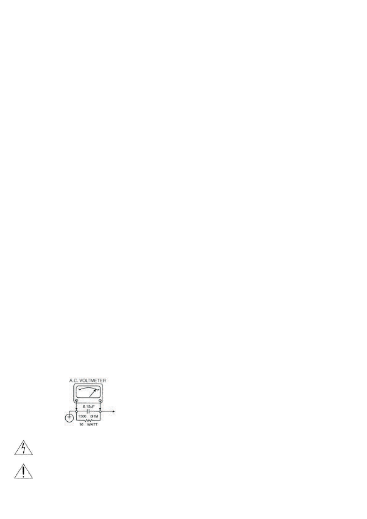
7. AFTER RE-ASSEMBLY OF THE SET, ALWAYS PERFORM AN A.C. LEAKAGE TEST ON ALL
EXPOSED METALLIC PARTS OF THE CABINET, (THE CHANNEL SELECTOR KNOB, ANTENNA
TERMINALS. HANDLE AND SCREWS) TO BE SURE THE SET IS SAFE TO OPERATE WITHOUT
DANGER OF ELECTRICAL SHOCK. DO NOT USE A LINE ISOLATION TRANSFORMER DURING
THIS TEST, MAKE SURE TO USE AN A.C. VOLTMETER. HAVING 5000 OHMS PER VOLT OR
MORE SENSITIVITY, IN THE FOLLOWING MANNER; CONNECT A 1500 OHMS 10 WATT
RESISTOR, PARALLELED BY A.15 MFD. 150V A.C. TYPE CAPACITOR BETWEEN A KNOWN
GOOD EARTH GROUND (WATER PIPE, CONDUIT, ETC.) AND THE EXPOSED METALLIC PARTS,
ONE AT A TIME. MEASURE THE A.C. VOLTAGE ACROSS THE COMBINATION OF 1500 OHM
RESISTOR AND 15 MFD CAPACITOR. REVERSE THE A.C. PLUG AND REPEAT A.C. ANY
VOLTAGE MEASUREMENTS FOR EACH EXPOSED METALLIC PART. VOLTAGE MEASURED
MUST NOT EXCEED 75 VOLTS R.M.S. THIS CORRESPONDS TO 0.5 MILLIAMP A.C. ANY
VALUE EXCEEDING THIS LIMIT CONSTITUTES A POTENTIAL SHOCK HAZARD AND MUST BE
CORRECTED IMMEDIATELY.
GOOD EARTH GROUND
SUCH AS THE WATER
PIPE, CONDUIT, ETC.
SUBJECT GRAPHIC SYMBOLS
PLACE THIS PROBE
ON EACH EXPOSED
METAL PART
SUBJECT: X-RADIATION
1.BE SURE PROCEDURES AND INSTRUCTIONS TO ALL SERVICE PERSONNEL COVER THE
SUBJECT OF X-RADIATION. THE ONLY POTENTIAL SOURCE OF X-RAYS IN CURRENT T.V.
RECEIVERS IS THE PICTURE TUBE. HOWEVER, THIS TUBE DOES NOT EMIT X-RYS WHEN THE
HIGH VOLTAGE IS AT THE FACTORY SPECIFIED LEVEL. THE PROPER VALUE IS GIVEN IN THE
APPLICABLE SCHEMATIC. OPERATION AT HIGHER VOLTAGES MAY CAUSE A FAILURE OF
THE PICTURE TUBE OR HIGH VOLTAGE SUPPLY AND, UNDER CERTAIN CIRCUMSTANCES,
MAY PRODUCE RADIATION IN EXCESS OF DESIRABLE LEVELS.
2. ONLY FACTORY SPECIFIED C.R.T ANODE CONNECTORS MUST BE USED
DEGAUSSING SHIELDS ALSO SERVE AS AN X-RAY SHIELD IN COLOR SETS,
ALWAYS RE-INSTALL THEM.
3. IT IS ESSENTIAL THAT SERVICE PERSONNEL HAVE AVAILABLE AN ACCURATE AND
RELIABLE HIGH VOLTAGE METER. THE CALIBRATION OF THE METER SHOULD BE CHECKED
PERIODICALLY AGAINST A REFERENCE STANDARD, SUCH AS THE ONE AVAILABLE AT YOUR
DISTRIBUTOR.
4. WHEN THE HIGH VOLTAGE CIRCUITRY IS OPERATING PROPERLY, THERE IS NO
POSSIBILITY OF AN ACCURATE AND RELIABLE HIGH VOLTAGE METER. THE CALIBRATION OF
THE METER SHOULD BE CHECKED PERIODICALLY AGAINST A REFERENCE STANDARD,
SUCH AS THE ONE AVAILABLE AT YOUR DISTRIBUTOR.
5. WHEN TROUBLESHOOTING AND MAKING TEST MEASUREMENTS IN A PRODUCT WITH A
PROBLEM OF EXCESSIVE HIGH VOLTAGE AVOID BEING UNNECESSARILY CLOSE TO THE
PICTURE TUBE AND THE HIGH VOLTAGE SUPPLY DO NOT OPERATE THE PRODUCT LONGER
THAN IT IS NECESSARY TO LOCATE THE CAUSE OF EXCESSIVE VOLTAGE.
6. REFER TO HV. B+ AND SHUTDOWN ADJUSTMENT PROCEDURES DESCRIBED IN THE
APPROPRIATE SCHEMATIC AND DIAGRAMS(WHERE USED).
SUBJECT: IMPLOSION
1. ALL DIRECT VIEWED PICTURE TUBES ARE EQUIPPED WITH AN INTEGRAL IMPLOSION
PROTECTION SYSTEM, BUT CARE SHOULD BE TAKEN TO AVOID DAMAGE DURING
INSTALLATION, AVOID SCRATCHING THE TUBE. IF SCRATCHED REPLACE IT.
2. USE ONLY RECOMMENDED FACTORY REPLACEMENT TUBES.
SUBJECT: TIPS ON PROPER INSTALLATION
1. NEVER INSTALL ANY PRODUCT IN A CLOSED-IN RECESS. CUBBYHOLE OR CLOSELY
FITTING SHELF SPACE, OVER OR CLOSE TO HEAT DUCT, OR IN THE PATH OF HEATED AIR
FLOW.
2. AVOID CONDITIONS OF HIGH HUMIDITY SUCH AS: OUTDOOR PATIO INSTALLATIONS
WHERE DEW IS A FACTOR, NEAR STEAM RADIATORS WHERE STEAM LEAKAGE IS A FACTOR,
ETC.
3. AVOID PLACEMENT WHERE DRAPERIES MAY OBSTRUCT REAR VENTING. THE CUSTOMER
SHOULD ALSO AVOID THE USE OF DECORATIVE. SCARVES OR OTHER COVERINGS WHICH
MIGHT OBSTRUCT VENTILATION.
4. WALL AND SHELF MOUNTED INSTALLATIONS USING A COMMERCIAL MOUNTING KIT,
MUST FOLLOW THE FACTORY APPROVED MOUNTING INSTRUCTIONS. A PRODUCT
MOUNTED TO A SHELF OR PLATFORM MUST RETAIN ITS ORIGINAL FEET (OR THE
EQUIVALENT THICKNESS IN SPACERS). TO PROVIDE ADEQUATE AIR FLOW ACROSS THE
BOTTOM. BOLTS OR SCREWS USED FOR FASTENERS MUST NOT TOUCH ANY PARTS OR
WIRING. PERFORM LEAKAGE TEST ON CUSTOMIZED INSTALLATIONS.
5. CAUTION CUSTOMERS AGAINST THE MOUNTING OF A PRODUCT ON SLOPING SHELF
OR A TILTED POSITION, UNLESS THE PRODUCT IS PROPERLY SECURED.
6. A PRODUCT ON A ROLL-ABOUT CART SHOULD BE STABLE ON ITS MOUNTING TO THE
CART CAUTION THE CUSTOMER ON THE HAZARDS OF TRYING TO ROLL A CART WITH
SMALL CASTERS ACROSS THRESHOLDS OR DEEP PILE CARPETS.
7. CAUTION CUSTOMERS AGAINST THE USE OF A CART OR STAND WHICH HAS NOT BEEN
LISTED BY UNDERWRITERS LABORATORIES, INC. FOR USE WITH THEIR SPECIFIC MODEL OF
TELEVISION RECEIVER OR GENERICALLY APPROVED FOR USE WITH TV'S OF THE SAME OR
LARGER SCREEN SIZE.
8. CAUTION CUSTOMERS AGAINST THE USE OF EXTENSION CORDS. EXPLAIN THAT A
FOREST OF EXTENSIONS SPROUTING FROM A SINGLE OUTLET CAN LEAD TO DISASTROUS
CONSEQUENCES TO HOME AND FAMILY.
The lightening flash with arrowhead symbol, within an equilateral
triangle, is intended to alert the user to the presence of uninsulated
"dangerous voltage" within the product's enclosure that may be of
sufficient magnitude to constitute a risk of electric shock to persons.
The exclamation point within an equilateral triangle is intended to alert
the user to the presence of important operating and maintenance
(servicing) instructions in the literature accompanying the appliance.
2

SERVICING PRECAUTIONS
CAUTION : Before servicing the DVD covered by this service
data and its supplements and ADDENDUMS, read and
follow the SAFETY PRECAUTIONS NOTE : if unforeseen
circumstances create conflict between the following
servicing precautions and any of the safety precautions in
this publications, always follow the safety Precautions.
Remember Safety First:
General Servicing Precautions
1. Always unplug the DVD DC power cord from the DC
power source before:
(1) Removing or reinstalling any component, circuit board,
module, or any other assembly.
(2) Disconnection or reconnecting any internal electrical
plug or other electrical connection.
Caution : A wrong part substitution or incorrect polarity
installation of electrolytic capacitors may result in an
explosion hazard.
2. Do not spray chemicals on or near this DVD or any of its
assemblies.
3. Unless specified otherwise in this service data, clean
electrical contacts by applying an appropriate contact
cleaning solution to the contacts with a pipe cleaner,
cotton-tipped swab, or comparable soft applicator.
Unless specified otherwise in this service data, lubrication
of contacts is not required.
Electrostatically Sensitive (ES) Devices
Some semiconductor (solid state) devices can be
damaged easily by static electricity. Such components
commonly are called Electrostatically Sensitive (ES) Devices.
Examples of typical ES devices are integrated circuits and
some field effect transistors and semiconductor chip
components. The following techniques should be used to
help reduce the incidence of component damage
caused by static electricity.
1. Immediately before handling any emiconductor
component or semiconductor-equipped assembly, drain
off any electrostatic charge on your body by touching a
known earth ground. Alternatively, obtain and wear a
commercially available discharging wrist strap device,
which should be removed for potential shock reasons
prior to applying power to the unit under test.
2. After removing an electrical assembly equipped with ES
devices, place the assembly on a conductive surface
such as aluminum toil, to prevent electrostatic charge
buildup or exposure of the assembly.
3. Use only a GROUNDED-tip soldering iron to solder or
unsolder ES devices.
4. Use only an anti-static solder removal device. Some
solder removal devices not classified a "anti-static" can
generate electrical charges sufficient to damage ES
devices.
4. Do not defeat any plug/socket B+ voltage interlocks with
which instruments covered by this service manual might
be equipped.
5. Do not apply AC power to this DVD and/or any of its
electrical assemblies unless all solid-state device heat
sinks are correctly installed
.
6. Always connect test instrument ground lead to the
appropriate ground before connection the test
instrument positive lead. Always remove the test
instrument ground lead last.
Insulation Checking Procedure
Disconnect the attachment plug trom the AC outlet and
turn the power on. Connect an insulation resistance
meter(500V) to the blades of the attachment plug. The
insulation resistance between each blade of the
attachment plug and accessible conductive parts (Note 1)
should be more than 1M ohm.
Note 1 : Accessible Conductive Parts including Metal
panels, input terminals, Earphone jacks, etc.
5. Do not use freon-propelled chemicals. These can
generate electrical charge sufficient to damage ES
devices.
6. Do not remove a replacement ES device from its
protective package until immediately before you are
ready to install it. (Most replacement ES devices are
packaged with leads electrically shorted together by
conductive foam, aluminum foil, or comparable
conductive material.)
7. Immediately before removing the protective material
from the leads of a replacement ES device, touch the
protective material to the chassis or circuit assembly into
which the device will be installed.
Caution : Be sure no power is applied to the chassis or
circuit, and observe all other safety precautions.
8. Minimize bodily motions when handling unpackaged
replacement ES devices. (Normally harmless motion
such as the brushing together of your clothes fabric or
the lifting of your foot from a carpeted floor can
generate static electricity sufficient to damage an ES
device.)
3
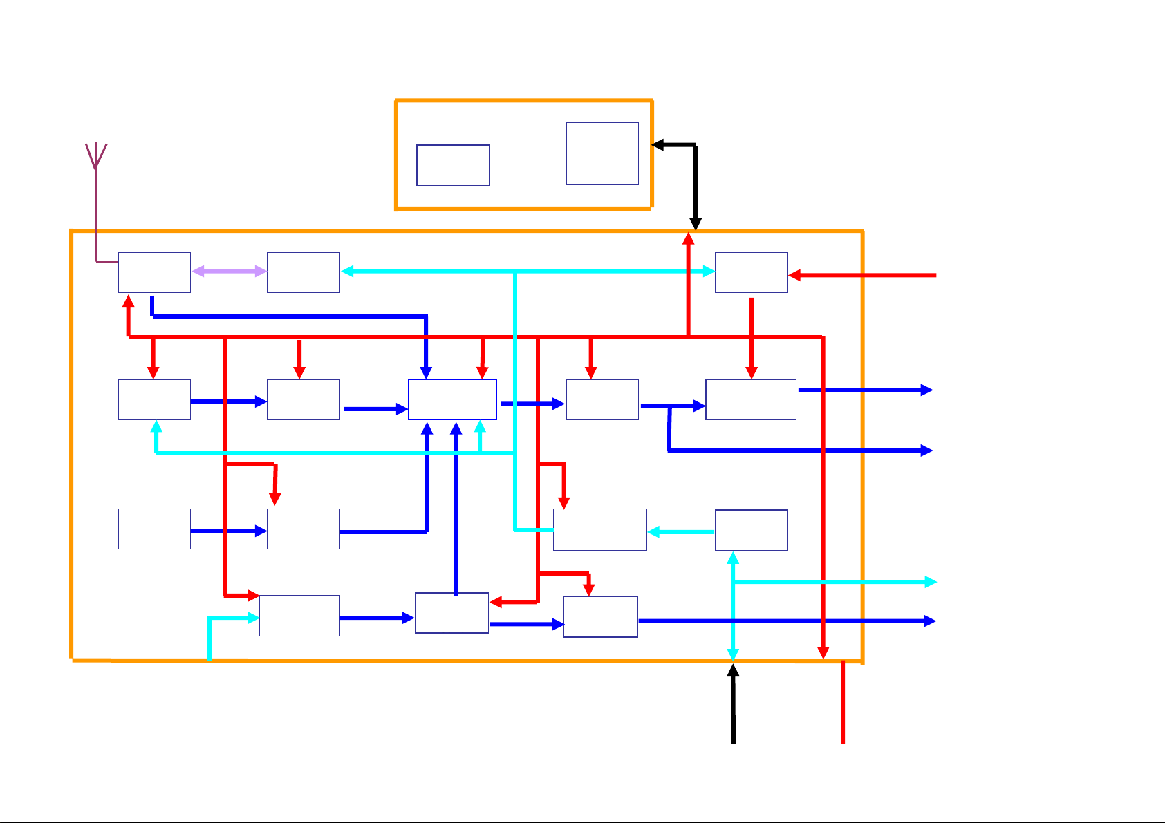
DV-100 BLOCK
DIAGRAM
LCD/KEY PCB
LCD
LCD/KEY
DRIVER
UPD16431
16 PIN CON
POWER D8V
MCU
FPSW
REMOTR
ENCODER
TUNER
FAE347
PLL
TC9257
T9V 2CH 100mV
B+ ACC
CDC
A9V A9V A12V
BA3121
2CH 1V
A9V VDD-5V
AUX-IN
BA3121
2CH 1V
A5V
MAIN
PCB
AUDIO D/A
CS4340
2CH 1V
POWER
SUPPLY
B+ ACC
B+ 4CH POWER OUT
AUDIO DSP
TEA6320
PRE AMP
2X4558
4CH 2V 4X25W
POWER AMP
TDA7381
2CH LINE OUT 2V
P5V
MCU
TMP87CM21D
LEVEL
3V3 TO 5V
2CH DIGITALL AUDIO
A9V
AUDIO
SW
A12V
PRE AMP
4558
2CH DVD REAR OUT
2V
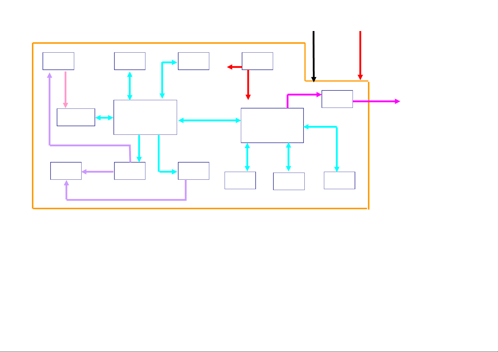
SHARP
HPD-50
RF-PREAMP
SP3721
FOCUS TRACK
EPROM
29C011
ALI DSP
SERVO
M5705
SDRAM
16M
DC12V
ATAPI INTERFACE
POWER
SUPPLY
DC1V8
DC3V3
DC5V
CIRRUS MPEG
CS98100
24PIN CON
MCU
DG AUDIO
SW
VIDEO BP
FILTERS
10PIN CON
POWER D12V D5V
LOAD MOTOER
2CH CVBS
MECHA
MOTOR
SLED
LOAD
DRIVER
BA5945
SPINDER MOTOR
DRIVER
BA6849
DVD-C01 SC
8M FLASH
29LV800
SDRAM
64M
EEPROM
AT24C02A
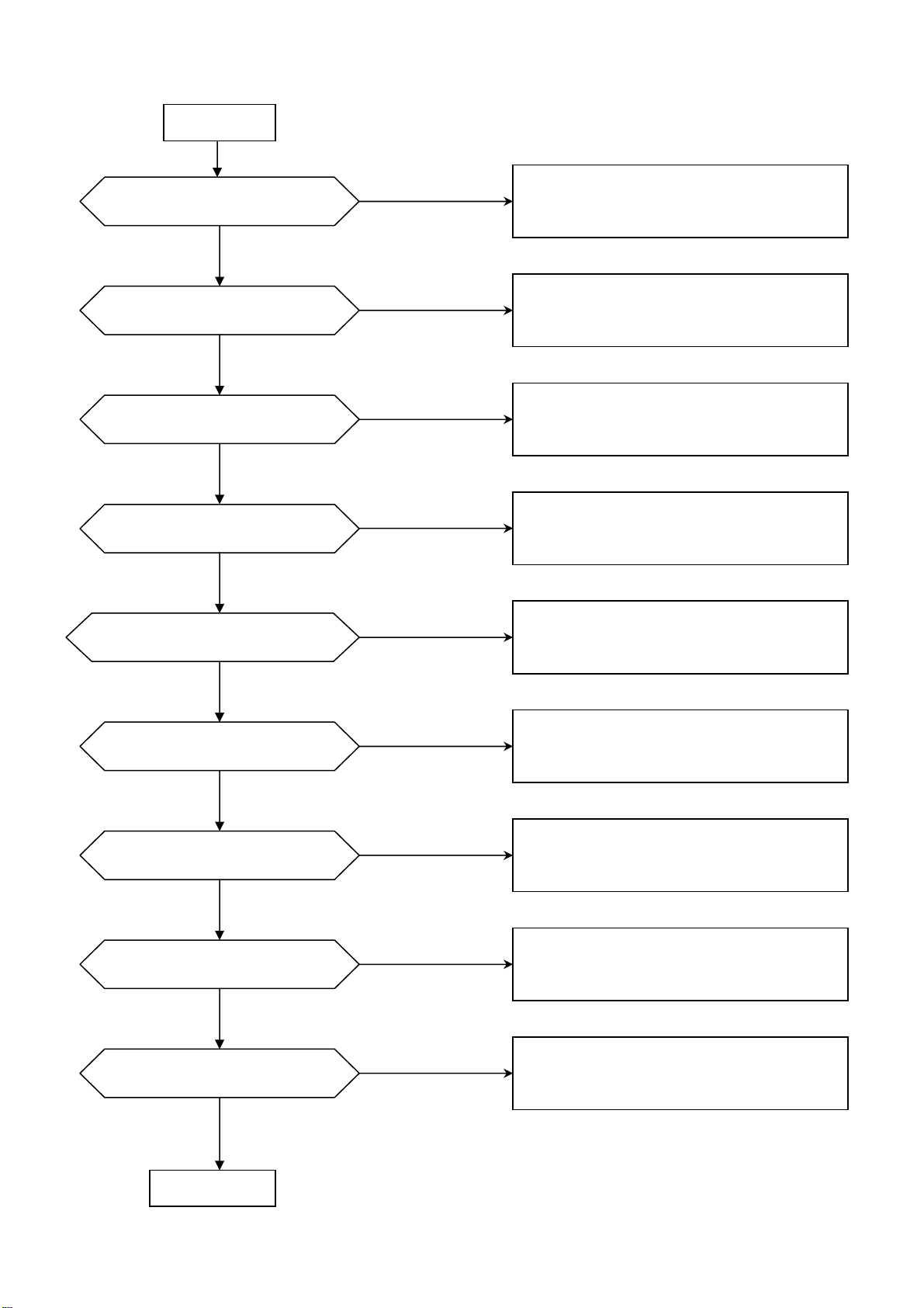
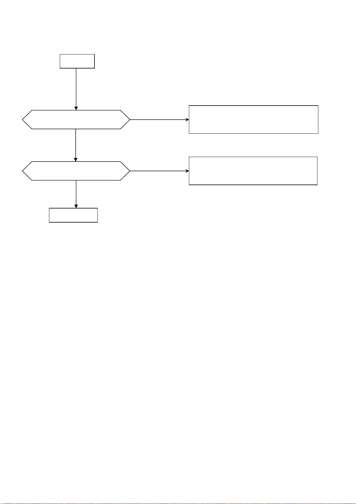
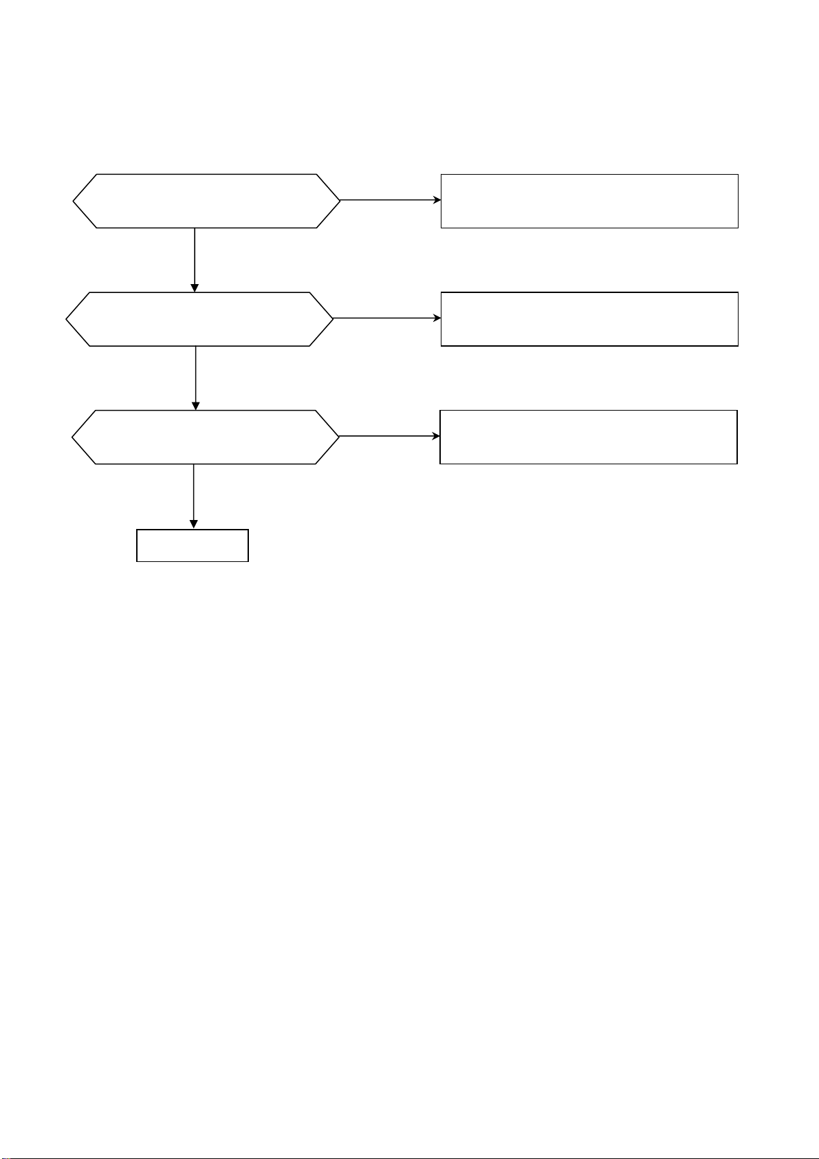
A Power Circuit abnormal (For main board)
Is the inout of Q419 DC 12V?
Is 40pin of U201 VDD-5V?
Is 26pin of U201 DC 12V?
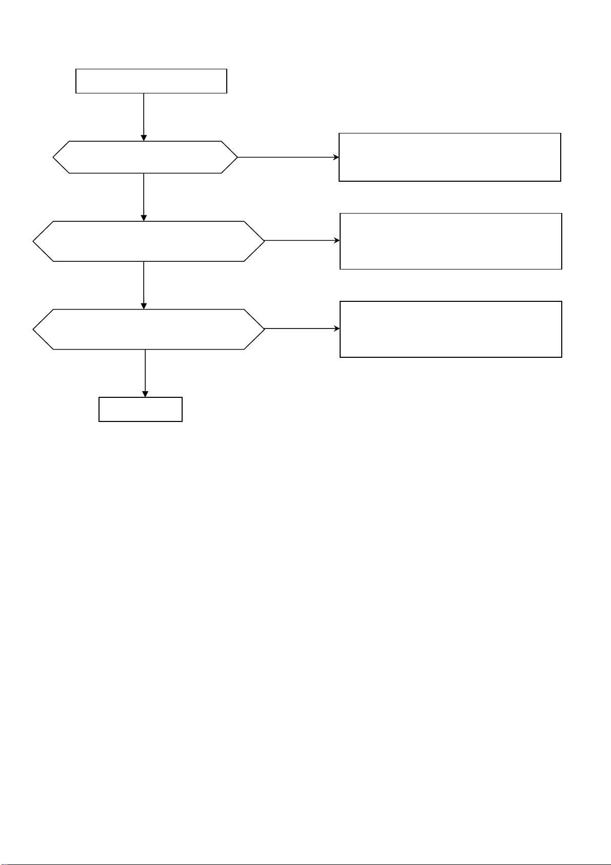
Is the out of Q404 DC 12V?
START
NO
Check the fuse.
YES
NO
Check Q401 ZD402 L401 and peripheral
components.
YES
NO
Check ACC and ACC fuse.
Check ZD401 and peripheral components.
YES
NO
Check Q404,Q408
YES
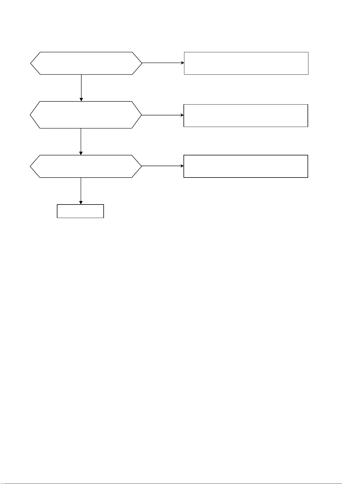
Is the output of U404 DC 5V?
YES
Is the out of Q402 P12V?
YES
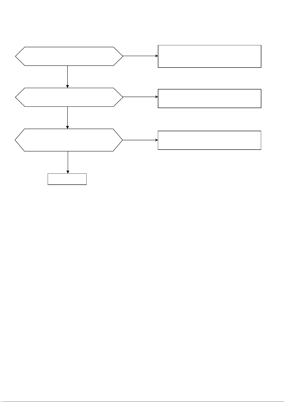
Is the out of U402 DC 8V?
YES
Is 2pin of U406 DC 3.3V?
YES
Is 2pin of U407 DC 1.8V?
NO
NO
NO
NO
NO
Check U404 and peripheral components.
Check Q402 Q406 and peripheral
components.
Check ZD439 and peripheral components.
Check U406 and peripheral components.
Check U407 and peripheral components.
YES
Normal
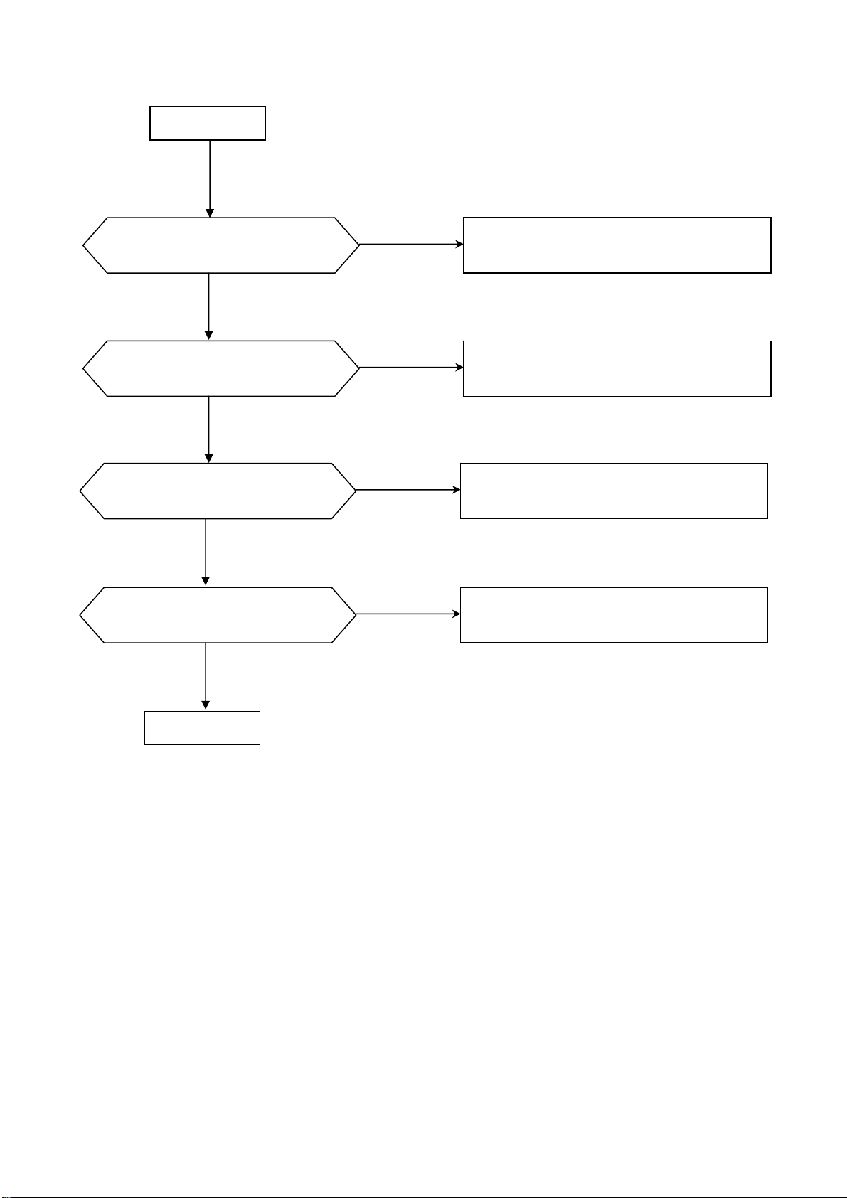
B Display abnormal (For main board)
START
YES
Does the screen appear?
YES
Is display normal?
YES
Normal
NO
NO
Check if the 14pin voltage of DC8V?
Check if the 16pin voltage of DC5V?
Check the key board according to key schematic.
Check the key board according to key
schematic.
C IN/OUT abnormal (For main board)
The disc can’t be injected
YES
Is 6pin of BA6951 DC 12V?
YES
Is voltage between 5 and 10 pin of BA6951
DC 4.6V after eject-key being pressed?
YES
Is voltage between 11 and 12 pin of J203 at
S&D board DC 4.5V?
NO
NO
NO
Check L2
1.Check CN401 at S&D board,connection between
it and MCU.
2.Check R204,BA6951.
Check connection between main board and S&D
board.
YES
Normal
D Logo display abnormal (For S&D board(Servo and Decoder board))
Is voltage for CN401 normal?
YES
No Logo display?
YES
Having picture,no color or color
disappeared during playback.
YES
Normal
NO
Check connection of main board and S&D
board.
NO
Check S&D board.
NO
Check decoder part and change Y101.
E Read disc abnormal (For S&D board)
DISC IN
Focus on?
YES
Is laser normal?
YES
Does the disc turn?
YES
Can TOC be read?
NO
NO
NO
NO
Refer to Focus abnormal.
Refer to laser abnormal.
Refer to disc turn abnormal.
Refer to TOC abnormal.
YES
Normal
F Video abnormal (For S&D board)
NO
Only Logo display
YES
YES
Having picture,no color or color
disappeared during playback.
NO
YES
Having picture,but picture
disappeared during playback.
Check the connection of U102 and ZR36776.
Check decoder part and change Y101.
Check decoder part and change Y101.
NO
Normal
G Audio abnormal (For main board)
Is the rear channel normal?
NO
Refer to rear out abnormal
YES
Is the front channel and
sbw channel normal?
YES
Is the power amplifier normal?
YES
Normal
NO
NO
Refer to front out abnormal
Check U301 and peripheral components

H T uner abnormal (For main board)
Auto search abnormal
Is 13pin of U101 DC 9V?
Is 12pin of U101 9V at FM mode
YES
Is X101 oscilating?
YES
and 0V at AM mode?
YES
Normal
NO
NO
NO
Check P9V,if P9V is 9V,
Check Q110 Q115 and peripheral components.
If P9V is 0V,check according to main board power
schematic.
Check TC9257 X101 and peripheral components
Check 17pin of TC9257,Q103,Q108 and
peripheral components
Auto search normal
but audio abnormal
YES
Is 3,4,29,30 pin of U503 normal?
YES
Normal
YES
RDS normal?
YES
NO
Check connection between 16,17 pin of
U101 and U503.
NO
Replace U503
NO
Check U707 and peripheral components.
Normal


复件 DV-202-LCD-KEY-V1.0.sch-1 - Tue May 30 12:38:14 2006


PART NUMBER PART NAME PART TYPE REF NO.
2-J111-0001-00-04
2-J130-00R5-00-03
2-J102-1R25-00-05
2-J110-0001-02-03
2-J124-0001-02-03
2-C29H-0105-M0-0A
2-C25H-0106-M0-0A
2-C25J-0476-M0-0A
2-C22J-0107-M0-0A
2-C25J-0107-M0-0A
2-C22J-0227-M0-0A
2-R41B-0000-J0-FA
2-R41B-0100-J0-FA
2-R41B-0330-J0-FA
2-R41B-0750-J0-FA
2-R41B-0101-J0-FA
2-R41B-0221-J0-FA
2-R41B-0331-J0-FA
2-R41B-0391-J0-FA
2-R41B-0102-J0-FA
2-R41B-0122-J0-FA
2-R41B-0152-J0-FA
2-R41B-0222-J0-FA
2-R41B-0332-J0-FA
2-R41B-0472-J0-FA
2-R41B-0512-J0-FA
2-R41B-0562-J0-FA
2-R41B-0822-F0-FA
FFC CON. 11PIN,1.0mm,
FFC CON. 30PIN,0.5mm,SO,
Socket 2PIN,1.25mm,SO,
Socket 10Pin,SMT)FFC-10
Socket 24Pin,
SMT E-CAP 1uF/50V,SMT,4(D)x5.3(L),±20%
SMT E-CAP 10uF/6.3V,SMT,4(D)x5.3(L),±20%
SMT E-CAP
SMT E-CAP
SMT E-CAP
SMT E-CAP
47uF/6.3V,SMT,6.3(D)x5.3(L),±
20%
100uF/6.3V,SMT,6.3(D)x5.3(L),±
20%
100uF/16V,SMT,6.3(D)x5.3(L),±
20%
220uF/6.3V,SMT,6.3(D)x5.3(L),±
20%
CHIP RES. 0603,0Ω,±5%,1/16W
CHIP RES. 0603,10Ω,±5% , 1/16W
CHIP RES. 0603,33Ω,±5% , 1/16W
CHIP RES. 0603,75Ω,±5% , 1/16W
CHIP RES. 0603,100Ω,±5% , 1/16W
CHIP RES. 0603,220Ω,±5% , 1/16W
CHIP RES. 0603,330Ω,±5% , 1/16W
CHIP RES. 0603,390Ω,±5% , 1/16W
CHIP RES. 0603,1KΩ,±5% , 1/16W
CHIP RES. 0603,1K2Ω,±5% , 1/16W
CHIP RES. 0603,1K5Ω,±5% , 1/16W
CHIP RES. 0603,2K2Ω,±5% , 1/16W
CHIP RES. 0603,3K3Ω,±5% , 1/16W
CHIP RES. 0603,4K7Ω,±5% , 1/16W
CHIP RES. 0603,5K1Ω,±5% , 1/16W
CHIP RES. 0603,5K6Ω,±5% , 1/16W
CHIP RES. 0603,8K2Ω,±1% , 1/16W
CN3
CN2
CN6-8
CN202
CN203
C88,C89
TC18,TC19-21,C81,C82,TC721
C46,TC30-33,TC37-44,C185
TC3-TC8,C45,C53,C84,C194,TC36
TC9
TC12-14
R49,R66,R215-R218,R106,R57
R23,R34,R43,R45,R97,R21-22
R15,R27-29,R77,R135,R91,R54
R48,R52,R99,R223-224
R55,R64,R65,R250,R252
R87,R94
R107
R24
R36, R205-206.R221,R742
R3
R41
R31,R33,R103,R165,R166
R10~12,R17,R80
R6,R18,R46,R104-105, R200-204
R25,R214,R5
R19
R26,R44
R4,R13,R20,R51,R68,R72,R74,R81,R
2-R41B-0103-J0-FA
CHIP RES. 0603,10KΩ,±5% , 1/16W
82,R108,R128,R167,R168,R208
210,R212,R213,R133-134
2-R41B-0123-J0-FA
2-R41B-0203-J0-FA
2-R41B-0223-J0-FA
2-R41B-0333-F0-FA
2-R41B-0473-J0-FA
2-R41B-0513-J0-FA
2-R41B-0563-J0-FA
2-R41B-0104-F0-FA
2-R41B-0474-J0-FA
2-R42C-0010-J0-FA
2-R42C-0100-J0-FA
2-C15B-0100-J0-NA
2-C15B-0180-J0-NA
2-C15B-0220-J0-NA
2-C15B-0240-J0-NA
2-C15B-0330-J0-NA
2-C15B-0470-J0-NA
2-C15B-0101-J0-NA
2-C15B-0271-J0-NA
2-C15B-0331-J0-NA
2-C15B-0471-K0-WA
2-C15B-0561-K0-WA
2-C15B-0681-K0-WA
2-C15B-0102-K0-WA
2-C15B-0222-K0-WA
2-C15B-0472-K0-WA
2-C15B-0682-K0-WA
2-C15B-0103-K0-WA
CHIP RES. 0603,12KΩ,±5% , 1/16W
CHIP RES. 0603,20KΩ,±5% , 1/16W
CHIP RES. 0603,22KΩ,±5% , 1/16W
CHIP RES. 0603,33KΩ,±1%,1/16W,
CHIP RES. 0603,47KΩ,±5% , 1/16W
CHIP RES. 0603,51kΩ,±5% , 1/16W
CHIP RES. 0603,56KΩ,±5% , 1/16W
CHIP RES. 0603,100KΩ,±1% , 1/16W
CHIP RES. 0603,470KΩ,±5% , 1/16W
CHIP RES. 0805,1Ω,±5% , 1/10W
CHIP RES. 0805,10Ω,±5% , 1/10W
Chip.Cap 0603,10p/16V,NPO,±5%
Chip.Cap 0603,18p/16V,NPO,±5%
Chip.Cap 0603,22p/16V,NPO,±5%
Chip.Cap 0603,24p/16V,NPO,±5%
Chip.Cap 0603,33p/16V,NPO,±5%
Chip.Cap 0603,47p/16V,NPO,±5%
Chip.Cap 0603,100p/16V,NPO,±5%
Chip.Cap 0603,270p/16V,NPO,±5%
Chip.Cap 0603,330p/16V,NPO,±5%
Chip.Cap 0603,470p/16V,X7R,±10%
Chip.Cap 0603,560p/16V,X7R,±10%
Chip.Cap 0603,680p/16V,X7R,±10%
Chip.Cap 0603,1n/16V,X7R,±10%
Chip.Cap 0603,2n2/16V,X7R,±10%
Chip.Cap 0603,4n7/16V,X7R,±10%
Chip.Cap 0603,6n8/16V,X7R,±10%
Chip.Cap 0603,10n/16V,X7R,±10%
R78
R7,R35,R37,R70,R211
R9
R73,R76,R111
R14,R50,R75,R79
R8
R2,R42
R1,R67,R95,R62,R747,R748
R115,R16,R53
R83~86,R88,R89
R96
C61~66
C57,C58
C118,C159
C100-101
C90,C97-99
C4
C69,C70,C42
C119,C161
C120,C160
C12,C13
C2
C37,C41
C7,C17,C18,C25,C34, C49,C43
C24
C71
C9
C14,C20,C31-32
~

2-C15B-0473-K0-WA
,
2-C15B-0104-K0-WA
2-C15B-0224-N0-YA
2-C13B-0474-N0-YA
2-R81B-0330-J0-FA
2-R81B-0470-J0-FA
2-R81B-0101-J0-FA
2-R81B-0103-J0-FA
2-L26E-0400-K0-0A
2-L25E-0001-K0-0A
2-L2EC-01R8-M0-0A
2-L25E-04R7-K0-0A
2-L60C-0600-KC-BA
2-L60C-0601-KC-BA
2-L66E-FB01-00-1A
2-T20C-3904-00-0A
2-T20D-4376-00-0A
2-T10D-1132-00-0A
2-D10B-4148-00-0A
2-D10M-4148-00-0A
2-UA0G-4558-00-0A
2-UA0G-8052-00-00
2-UM0H-5706-00-C0
2-UA0G-24C0-02-00
2-UA0G-5954-00-0A
2-UA0G-6849-00-0A
2-UA0G-M393-00-00
2-UA00-9164-00-0A
2-UM0H-3721-00-C0
2-UD0G-1M16-00-0A
2-UA00-4340-00-00
2-UA0N-4911-00-00
2-UM00-6748-00-00
2-UA0Q-VF80-00-00
2-X450-0000-27-ME
2-X450-33M8-68-8E
2-J106-1R25-01-00
2-J105-0002-00-01
2-Q312-1037-00-0A
Chip.Cap 0603,47n/16V,X7R,±10%
Chip.Cap 0603,0.1u/16V,X7R,±10%
Chip.Cap 0603,0.22u/16V,Y5V,+80%-20%
Chip.Cap 0603,0.47u/10V,Y5V,+80%-20%
CHIP NETWORK.
RES.
CHIP NETWORK.
RES.
CHIP NETWORK.
RES.
CHIP NETWORK.
RES.
0603,33Ωx4,±5% , 1/16W
0603,47Ωx4,±5% , 1/16W
0603,100Ωx4,±5% , 1/16W
0603,10KΩx4,±5% , 1/16W
chip inductor 1206,40uH
chip inductor 1206,1uH
chip inductor 0805,1.8uH
chip inductor 1206,4.7uH
Chip bead 0805,600
Chip bead 0805,601
Chip bead 1206,121
Transistor PMBT3904,SOT-23
Transistor KTC4376, SOT-89,BCE,NPN
Transistor 2SB1132, SOT-89,BCE,PNP
DIODE 1N4148
DIODE 1N4148, LLDS-35,
DUAL AMP NJM4558 SOP-8
OP AMP AD8052 SOIC8
DVD-ROM
Controller
M5706 QFP176D
EEPROM AT24C02, SOP8
DRIVER IC BA5954FP,HSOP-28
DRIVER IC BA6849FM,HSOP-28
OP AMP LM393,SOP8
VOL. REG.3.3V RT9164,SOT-223
RF FRONT END SP3721 (宽温) QFP64D
SDRAM HY57V161610D (16M)
Audio D/A CS4340-kS,SOIC16
EEPROM W29C011AP,PLCC32D
MPEG CHIP ZR36748,PQFP208
8M FLASH MBM29LV800,TSOP-48
Crystal
27M,CL=24pF,±10ppm
Crystal 33.8688M,CL=14.7pF,
Socket 6PIN,1.25mm,
Socket 5PIN,2.0mm,
SWITCH MPU10371MLB0
2-B032-0115-06-00 PCB FR-4,,1.0mm
2-A410-7121-R5-00 SPONGE MAT 7X12X1.5
2-A410-7075-R5-00 SPONGE MAT
2-A410-6241-R5-00
1-1005-5003-00-00
X-2506-0001-00-00
PVC MAT
XP SCREW
DVD LOADER
7*7*5.0
6*2.4*1.0
M2*4
DVD-C01
C1,C11,C39,C136
BC1-5,BC10-
21,BC23,BC24,C3,C5,C6,C8,C15,C16
,C19,C21-23,C26-
30,C35,C38,C44,C47-48,C50-52,C54-
56,C59,C68,C72-
77,C79,C80,C83,C85,C86,C87,C91,C
93,C94,C115-117,C180-
183
C197,C500-505,C507-
C60
C10,C92
RN2,RN20-23
RN1
RN13~16
RN7~12
L2,L3
L10
L7,L20
L22-25
FB15-16
FB27-31FB10-11FB13-14FB20-24
FB1-9FB12FB19FB701
Q5,Q9,Q707
Q3
Q1,Q2
D4,D10
D1-D3,D5-D9
U3
U16
U1
U6
U9
U10
U11
U13-U14
U2
U7,U8
U502
U4
U5
U12
Y1
Y3
CN5
CN204
S1

Part Number Part Name Part type REF NO.
N
N
Q
r
r
r
r
,
r
r
r
2-UD0K-21DF-01-00 8-BIT MCU TMP87CM21DF U201
2-UD0G-6320-00-00 ASP IC TEA6320T U503
2-UA0G-3121-00-00 DUAL AMP BA3121F U501,U504
2-UD0G-9257-01-00 PLL TC9257F U102
2-UA00-7029-00-0A RESET REGULATOR KIA7029AF U202
2-UA0G-4558-00-0A DUAL AMP
2-UA0G-4053-00-00 3CH SW HEF 4053BT , U603
2-UA0B-7809-00-00
2-T20D-4375-00-0A Transistor
2-T10J-1663-00-0A Transistor PNP,KTA1663, Q109,Q403,Q409
2-T201-231S-00-00 Transistor KRC231S, Q601,Q603,Q609,Q610
2-T20C-3904-00-0A Transistor 2N3904S,
2-T20C-3882-00-0A Transistor KTC3882, Q202,Q203,Q204
2-T10C-3906-00-0A Transistor 2N3906S, Q101,Q102,Q201,Q304,Q602,Q607
2-E200-7205-00-00 MOS IRF7205 Q402,Q404
2-E200-6402-00-00 MOS ML6402, Q405
2-L26E-0100-K0-0A LEAD 10uH L101
2-L65C-FB01-00-1A BEAD COIL FERB/0805/1A
2-R43E-0010-J0-FA Chip Resistor 1Ω±5%,1/8W
2-R43E-0680-J0-FA Chip Resisto
2-R41B-0000-J0-FA Chip Resisto
2-R41B-0101-J0-FA Chip Resistor 100Ω±5%, 1/16W
VOLTAGE
REGULATOR
JM4558N, U601,U602,U604
78D09, U402
PN,KTC4375Y, Q401
Q103~Q108,Q110,Q301~Q303,Q305,
306,Q406~Q408,Q410,Q605,Q606
FB302~FB305,FB306,FB601~FB606,
FB201~FB213,FB401~FB404,FB501
~FB504,FB607~FB617
R205,R245,R425,R426,R429,R430,R
438,R439
68Ω±5%,1/8W R442,R443
0Ω±5%, 1/16W R113,R350,(R503,R527,R532)
R102,R112,R348,R530,R611,R626,R
647,R648,R667
2-R41B-0331-J0-FA Chip Resistor 330Ω±5%, 1/16W R232,R604,R608,R619,R623
2-R41B-0221-J0-FA Chip Resistor 220Ω±5%, 1/16W R605,R620,R642
2-R41B-0681-J0-FA Chip Resistor 680Ω±5%, 1/16W R130
R105,R106,R109,R115,R121,R125~R
2-R41B-0102-J0-FA Chip Resistor 1KΩ ±5%, 1/16W
2-R41B-0222-J0-FA Chip Resistor 2.2KΩ±5%, 1/16W
2-R41B-0332-J0-FA Chip Resisto
2-R41B-0392-J0-FA Chip Resisto
2-R41B-0472-J0-FA Chip Resistor 4.7KΩ±5%, 1/16W
2-R41B-0562-J0-FA Chip Resistor 5.6KΩ±5%, 1/16W
2-R41B-0682-J0-FA Chip Resistor 6.8KΩ ±5%, 1/16W
2-R41B-0103-J0-FA Chip Resistor 10KΩ±5%, 1/16W
2-R41B-0153-J0-FA Chip Resisto
2-R41B-0183-J0-FA Chip Resisto
2-R41B-0273-J0-FA Chip Resisto
3.3KΩ ±5%, 1/16W R303,R231
3.9KΩ ±5%, 1/16W R603,R606,R618,R621,R638,R639
15KΩ±5%, 1/16W R116,R406,R407,R505,R511
18KΩ±5%, 1/16W R669,R670
27KΩ±5%, 1/16W R332,R414,R441
127,R129,R131,R201,R202,R244,R24
8~R254,R334~R337,R403,R512,R51
3,R421
R103,R104,R108,R110,R117,R132,R
207~R210,R246,R522,R524,R663,R6
R118,R214~R218,R255,R346,R404,R
401,R402,R521,R525,R609,R610,R62
4,R625,R628,R640,R643,R644,R654,
R655
R662,R666
R101,R111,R133,R629,R632,R633,R
656,R657
R128,R410,R508,R509,R518,R520,R
533~R536,R510,R516
R119,R123,R124,R134,R219~R221,R
247,R311~R313,R315,R331,R347,R4
08,R409,R501,R502,R504,R515,R658
,R659,R661,R673,R528

2-R41B-0303-J0-FA Chip Resistor 30KΩ±5%, 1/16W
r
r
2-R41B-0333-J0-FA Chip Resisto
2-R41B-0473-J0-FA Chip Resistor 47KΩ±5%, 1/16W
2-R41B-0104-J0-FA Chip Resistor 100KΩ±5%, 1/16W
2-R41B-0184-J0-FA Chip Resisto
2-C15B-0200-J0-NA Chip Capacitor 20p/16V, NPO, ±5% C222,C223
2-C15B-0270-J0-NA Chip Capacitor 27p/16V, NPO, ±5% C220,C221
2-C15B-0330-J0-NA Chip Capacitor 33p/16V, NPO, ±5% C117,C118
2-C15B-0151-K0-WA Chip Capacitor 150p/16V,X7R,±10% C606,C609,C616,C622,C634,C635
2-C15B-0471-K0-WA Chip Capacitor 470p/16V,X7R,±10% C406
2-C15B-0102-K0-WA Chip Capacitor 102/16V, X7R,±10%
2-C15B-0152-K0-WA Chip Capacitor 152/16V, X7R,±10% C602,C605,C615,C619,C630,C631
2-C15B-0562-K0-WA Chip Capacitor 562/16V, X7R,±10% C533,C534
2-C15B-0822-K0-WA Chip Capacitor 822/16V, X7R,±10% C526,C529
2-C15B-0103-K0-WA Chip Capacitor 103/16V,X7R,±10%
33KΩ,±5%, 1/16W R242,R506,R519
180KΩ±5%, 1/16W R411,R413,R415
R507,R514,R602,R607,R616,R622,R
636,R637
R107,R114,R120,R122,R222~R230,R
314,R333,R343,R344,R412,R613,R61
4,R651,R653,R671,R672,R422
R233~R237,R240,R241,R243,R305,R
342,R431
C115,C218,C219,C229,C303~C306,C
626
C101~C103,C105,C106,C109~C114,
C116,C119,C120,C122~C124,C201~
C207,C209,C210,C212~C216,C224,C
225,C227,C228,C320,C327~C334,C4
01,C402,C405,C412,C413,C430,C431
,C536,C604,C612,C618,C633,C639,R
526
2-C15B-0153-K0-WA Chip Capacitor 153/16V,X7R,±10% C107,C108
2-C15B-0223-K0-WA Chip Capacitor 223/16V,X7R,±10% C104
2-C15B-0333-M0-YA Chip Capacitor 333/16V,Y5V,±20% C531,C532
2-C15B-0104-N0-YA Chip Capacitor
2-C15B-0224-N0-YA Chip Capacitor
2-B032-0122-04-00 MAIN PCB
2-UA0C-1641-01-40 MOTOR DRIVER LB1641, U203
2-UM0B-2576-00-00 REG CM2576S-5, TO-220 U404
2-L150-0101-00-00 LEAD L201
2-L010-0222-00-00 LEAD AX445-27692.2MH/15A L301
2-D100-5401-00-00 CHIP DIODE D307
2-D101-4148-00-1B SWITCHING DIODE
2-Q312-1120-00-00 DS-1120B SW202
2-Q212-1102-00-30 SWICHING T1102VA SW203
2-Z001-E347-0U-S1 TUNER FAE347-A29 U101
2-L400-0332-K0-00 Inductance L102
2-L560-0101-K0-00 LEAD 100uH/D10*14/1A L402
2-L150-0471-00-00 LEAD L401
2-DZ00-04R7-00-00 ZENER DIODE ZD201
2-DZ00-05R1-00-00 ZENER DIODE ZD202,ZD401
2-DZ00-05R6-00-00 ZENER DIODE ZD402,ZD203~ZD206
2-D100-5822-00-00 ZENER DIODE IN5822 ZD403
2-X070-032K-76-8B XTAL X202
2-X450-0000-7M-2E XTAL 7.2MHz±10PPM X101
2-X450-0000-08-ME XTAL 8.00MHz±10PPM X201
104/16V, Y5V,﹢80/-20%
224/16V, Y5V,﹢80/-20%
C211,C307,C407
C528,C530
D101~D104,D202~D204,206,D207,D
209~D214,D216,D301~D306,D308,D
309,(D205,D201,D208,D215)

2-R600-6003-00-00 KT60-0300B PH401,RH402
C129,C302,C130,C132,C426,C535,C
2-C570-0015-J0-00 Chip Capacitor 103M/16V,±10% C121
2-C292-0474-M0-00 Alu. Cap. Elect. CD11C-0.47uF/50V ±20% C323~C326
2-C292-0105-M0-00 Alu. Cap. Elect. CD11C-1uF/50V ±20% C308,C322,C613,C318,C640
2-C292-0225-M0-00 Alu. Cap. Elect. CD11C-2.2uF/50V ±20% C133,C134
C127,C128,C131,C321,C410,C420,C
422,C503,C504,C506~C508,C510,C5
11,C517,C518,C520,C521,C523~C52
2-C252-0106-M0-0D Alu. Cap. Elect. 10uF/16V, ±20%
2-C252-0226-M0-0D Alu. Cap. Elect. 22uF/16V, ±20% C125,C126
2-C253-0476-M0-0D Alu. Cap. Elect. 47uF/16V, ±20%
5,C538,C541,C542,C544,C546,C547,
C601,C607,C610,C611,C614,C620,C
623,C624,C628,C629,C636,C637,C64
1
2-C234-0107-M0-00 Alu. Cap. Elect. 100uF/10V, ±20%
2-C254-0107-M0-0D Alu. Cap. Elect. 100uF/16V, ±20% C226,C319,C415,C419,C421
2-C225-0227-M0-00 Alu. Cap. Elect. 220uF/6.3V, ±20% C217,C423
2-C255-0227-M0-0D Alu. Cap. Elect. 220uF/16V, ±20% C608,C621,C638
2-C25Z-0108-M0-00 Alu. Cap. Elect. 1000uF/16V,,±20% C432
2-C22F-0228-M0-0D Alu. Cap. Elect. 2200uF/6.3V±20% C418
2-C25G-0338-00-00 Alu. Cap. Elect. 3300uF/16V, ±20% C429
2-W000-2100-03-00
2-W614-FP01-00-00 FUSE 15A
2-J110-0CDC-00-00 CDCHANGE CN501
2-J104-0002-01-01
2-J110-0001-02-06
2-J124-0001-02-01
2-J116-0001-01-01 16-PINCONNECTOR CN201
2-J116-02R5-MO-01
2-UA00-7381-00-00 POWER AMP TDA7381 U301
2-W110-0070-00-15 10PINFFC
2-W116-0080-00-15 16PINFFC
2-W124-0090-00-15 24PINFFC
2-W000-2100-07-01
2-W000-2100-01-00
2-2100-REMT-01-00
2-W000-2100-02-00
Part Number Part Name Part type REF NO.
2-R41B-0000-J0-FA CHIP RESISTER
2-R41B-0470-J0-FA CHIP RESISTER
2-R41B-0121-J0-FA CHIP RESISTER
2-R41B-0101-J0-FA CHIP RESISTER
2-R41B-0102-J0-FA CHIP RESISTER
2-R41B-0472-J0-FA CHIP RESISTER
2-R41B-0222-J0-FA CHIP RESISTER
2-R41B-0103-J0-FA CHIP RESISTER
4 PIN CABLE
CONNECTOR
10PIN CABLE
CONNECTOR
24 PIN CABLE
CONNECTOR
16-PIN
CONNECTOR
0Ω±5% 1/16W
47Ω±5% 1/16W
120Ω,±5% , 1/16W
100Ω,±5% , 1/16W
1KΩ±5% 1/16W
4.7KΩ±5% 1/16W
2.2KΩ±5% 1/16W
10KΩ±5% 1/16W
C408,C416,C424,C427,C519,C603,C
617,C632,C502,C505,C543,C545
CN604CN1CN2
CN602
CN603
CN301
R24
R9
R13~R21,R30~R32,R4,R5,R22,R23
R28
R3,R36
R33,R34
R8,R11
R6,R10,R27,R29,R35

2-R41B-0473-J0-FA CHIP RESISTER
r
(
)
(
)
(
)
t
t
t
)
2-R41B-0104-J0-FA CHIP RESISTER
2-C15B-0103-K0-WA CHIP CAPACITOR
2-DZ00-03R9-00-0A Zene
2-Y23X-1721-40-00 SMD LED
2-Q212-3MBS-00-00 TACT SWITCH
2-L65C-FB01-00-1A BEAD COIL
2-UA0H-6431-00-00
2-T10J-1663-00-0A Transistor
2-T20C-3904-00-0A Transistor
2-J216-0001-MI-08
2-C236-0476-M0-0D Alu. Cap. Elect.
2-D101-4148-00-1B SWITCHING DIODE
2-UM00-3809-00-00 Remote Rec
2-Q935-ENCO-00-0B ENCODER
2-Y502-5908-20-41
2-Y76X-3021-00-05 LED BL1
2-B032-0123-05-00 KEY BOARD
2-R41B-0102-J0-FA CHIP RESISTER
2-J116-0001-02-06 FFC CONNECTOR CON2
2-Y23X-1721-40-00 SMD LED D33~D34
2-Q212-1523-00-00 TACT SWITCH
2-J116-0001-MI-08
2-B032-0127-03-00 EO BOARD
2-J111-0001-00-04 FFC CON. CN3
2-J130-00R5-00-03 FFC CON. CN2
2-J102-1R25-00-05 Socke
2-J110-0001-02-03 Socke
2-J124-0001-02-03 Socke
2-C29H-0105-M0-0A SMT E-CAP 1uF/50V,SMT,4(D)x5.3(L),± C88,C89
2-C25H-0106-M0-0A SMT E-CAP
2-C25J-0476-M0-0A SMT E-CAP
2-C22J-0107-M0-0A SMT E-CAP
2-C25J-0107-M0-0A SMT E-CAP
2-C22J-0227-M0-0A SMT E-CAP
2-R41B-0000-J0-FA CHIP RES. 0603,0Ω,±5%,1/16W R49,R66,R215-R218,R106,R57
2-R41B-0100-J0-FA CHIP RES. 0603,10Ω,±5% , 1/16W R23,R34,R43,R45,R97,R21-22
2-R41B-0330-J0-FA CHIP RES. 0603,33Ω,±5% , 1/16W R15,R27-29,R77,R135,R91,R54
2-R41B-0750-J0-FA CHIP RES. 0603,75Ω,±5% , 1/16W R48,R52,R99,R223-224
2-R41B-0101-J0-FA CHIP RES. 0603,100Ω,±5% , 1/16W R55,R64,R65,R250,R252
2-R41B-0221-J0-FA CHIP RES. 0603,220Ω,±5% , 1/16W R87,R94
2-R41B-0331-J0-FA CHIP RES. 0603,330Ω,±5% , 1/16W R107
2-R41B-0391-J0-FA CHIP RES. 0603,390Ω,±5% , 1/16W R24
2-R41B-0102-J0-FA CHIP RES. 0603,1KΩ,±5% , 1/16W R36, R205-206.R221,R742
2-R41B-0122-J0-FA CHIP RES. 0603,1K2Ω,±5% , 1/16W R3
2-R41B-0152-J0-FA CHIP RES. 0603,1K5Ω,±5% , 1/16W R41
2-R41B-0222-J0-FA CHIP RES. 0603,2K2Ω,±5% , 1/16W R31,R33,R103,R165,R166
2-R41B-0332-J0-FA CHIP RES. 0603,3K3Ω,±5% , 1/16W
2-R41B-0472-J0-FA CHIP RES. 0603,4K7Ω,±5% , 1/16W R6,R18,R46,R104-105, R200-204
2-R41B-0512-J0-FA CHIP RES. 0603,5K1Ω,±5% , 1/16W R25,R214,R5
2-R41B-0562-J0-FA CHIP RES. 0603,5K6Ω,±5% , 1/16W R19
LCD驱动片
16PINCONNECTOR
液晶显示屏
16-PIN
CONNECTOR
母
47KΩ±5%, 1/16W
100KΩ±5% 1/16W
103/16V,X7R,±10%
3V9
RED
6.0x3.5x5.0
FERB/0805/1A
UPD16431A
PNP,KTA1663
2N3904S
CAM-C73
公
47uF/10V, ±20%
RLS4148
RPM6938
13.4L*14.5W*14.5H
1KΩ±5% 1/16W
HCT-11523
CAM-C74
10uF/6.3V,SMT,4(D)x5.3(L),±
20%
47uF/6.3V,SMT,6.3(D)x5.3(L),
±20%
100uF/6.3V,SMT,6.3(D)x5.3(L
),±20%
100uF/16V,SMT,6.3(D)x5.3(L)
,±20%
220uF/6.3V,SMT,6.3(D)x5.3(L
,±20%
ISS133
R2,R7,R12
R1
C4
Z1
D8~D32
K1~K17
FB1~FB10
U1
Q2
Q1
CON3
C1,C5
D1~D6
U2
EN1
LCD1
R37
K18
CON1
CN6-8
CN202
CN203
TC18,TC19-21,C81,C82,TC721
C46,TC30-33,TC37-44,C185
TC3-TC8,C45,C53,C84,C194,TC36
TC9
TC12-14
R10~12,R17,R80

2-R41B-0822-F0-FA CHIP RES. 0603,8K2Ω,±1% , 1/16W R26,R44
,
,
R4,R13,R20,R51,R68,R72,R74,R81,R
2-R41B-0103-J0-FA CHIP RES. 0603,10KΩ,±5% , 1/16W
2-R41B-0123-J0-FA CHIP RES. 0603,12KΩ,±5% , 1/16W R78
2-R41B-0203-J0-FA CHIP RES. 0603,20KΩ,±5% , 1/16W R7,R35,R37,R70,R211
2-R41B-0223-J0-FA CHIP RES. 0603,22KΩ,±5% , 1/16W R9
2-R41B-0333-F0-FA CHIP RES.
2-R41B-0473-J0-FA CHIP RES. 0603,47KΩ,±5% , 1/16W R14,R50,R75,R79
2-R41B-0513-J0-FA CHIP RES. 0603,51kΩ,±5% , 1/16W R8
2-R41B-0563-J0-FA CHIP RES. 0603,56KΩ,±5% , 1/16W R2,R42
2-R41B-0104-F0-FA CHIP RES. 0603,100KΩ,±1% , 1/16W R1,R67,R95,R62,R747,R748
2-R41B-0474-J0-FA CHIP RES. 0603,470KΩ,±5% , 1/16W R115,R16,R53
2-R42C-0010-J0-FA CHIP RES. 0805,1Ω,±5% , 1/10W
2-R42C-0100-J0-FA CHIP RES. 0805,10Ω,±5% , 1/10W R96
2-C15B-0100-J0-NA Chip.Cap 0603,10p/16V,NPO,±5%
2-C15B-0180-J0-NA Chip.Cap 0603,18p/16V,NPO,±5% C57,C58
2-C15B-0220-J0-NA Chip.Cap 0603,22p/16V,NPO,±5% C118,C159
2-C15B-0240-J0-NA Chip.Cap 0603,24p/16V,NPO,±5% C100-101
2-C15B-0330-J0-NA Chip.Cap 0603,33p/16V,NPO,±5% C90,C97-99
2-C15B-0470-J0-NA Chip.Cap 0603,47p/16V,NPO,±5% C4
2-C15B-0101-J0-NA Chip.Cap 0603,100p/16V,NPO,±5% C69,C70,C42
2-C15B-0271-J0-NA Chip.Cap 0603,270p/16V,NPO,±5% C119,C161
2-C15B-0331-J0-NA Chip.Cap 0603,330p/16V,NPO,±5% C120,C160
2-C15B-0471-K0-WA Chip.Cap 0603,470p/16V,X7R,±10% C12,C13
2-C15B-0561-K0-WA Chip.Cap 0603,560p/16V,X7R,±10% C2
2-C15B-0681-K0-WA Chip.Cap 0603,680p/16V,X7R,±10% C37,C41
2-C15B-0102-K0-WA Chip.Cap 0603,1n/16V,X7R,±10% C7,C17,C18,C25,C34, C49,C43
2-C15B-0222-K0-WA Chip.Cap 0603,2n2/16V,X7R,±10% C24
2-C15B-0472-K0-WA Chip.Cap 0603,4n7/16V,X7R,±10% C71
2-C15B-0682-K0-WA Chip.Cap 0603,6n8/16V,X7R,±10% C9
2-C15B-0103-K0-WA Chip.Cap 0603,10n/16V,X7R,±10% C14,C20,C31-32
2-C15B-0473-K0-WA Chip.Cap 0603,47n/16V,X7R,±10% C1,C11,C39,C136
2-C15B-0104-K0-WA Chip.Cap 0603,0.1u/16V,X7R,±10%
2-C15B-0224-N0-YA Chip.Cap 0603,0.22u/16V,Y5V,+80%- C60
2-C13B-0474-N0-YA Chip.Cap 0603,0.47u/10V,Y5V,+80%- C10,C92
2-R81B-0330-J0-FA CHIP NETWORK. 0603,33Ωx4,±5% , 1/16W RN2,RN20-23
2-R81B-0470-J0-FA CHIP NETWORK. 0603,47Ωx4,±5% , 1/16W RN1
2-R81B-0101-J0-FA CHIP NETWORK. 0603,100Ωx4,±5% , 1/16W
2-R81B-0103-J0-FA CHIP NETWORK. 0603,10KΩx4,±5% , 1/16W
2-L26E-0400-K0-0A chip inductor 1206,40uH L2,L3
2-L25E-0001-K0-0A chip inductor 1206,1uH L10
2-L2EC-01R8-M0-0A chip inductor 0805,1.8uH L7,L20
2-L25E-04R7-K0-0A chip inductor 1206,4.7uH L22-25
2-L60C-0600-KC-BA Chip bead 0805,600 FB15-16
2-L60C-0601-KC-BA Chip bead 0805,601 FB27-31FB10-11FB13-14FB20-24
2-L66E-FB01-00-1A Chip bead 1206,121 FB1-9FB12FB19FB701
2-T20C-3904-00-0A Transistor PMBT3904,SOT-23 Q5,Q9,Q707
2-T20D-4376-00-0A Transistor KTC4376, SOT-89,BCE,NPN Q3
2-T10D-1132-00-0A Transistor 2SB1132, SOT-89,BCE,PNP Q1,Q2
2-D10B-4148-00-0A DIODE 1N4148 D4,D10
0603,33KΩ,±1%,1/16W,
82,R108,R128,R167,R168,R208~
210
R212,R213,R133-134
R73,R76,R111
R83~86,R88,R89
C61~66
BC1-5,BC1021,BC23,BC24,C3,C5,C6,C8,C15,C1
6,C19,C21-23,C2630,C35,C38,C44,C47-48,C50-52,C5456,C59,C68,C7277,C79,C80,C83,C85,C86,C87,C91,C
93,C94,C115-117,C180183,C197,C500-505,C507C511
C516-531,C722
RN13~16
RN7~12

2-D10M-4148-00-0A DIODE D1-D3,D5-D9
N
A
l
l
t
R
R
,
R
,
R
,
R
,
R
,R7,
R
R
r
Q
L
r
Q
r
Q
(
p
/
,
(
)
Q
R
/
R
R
,
Q
R
2-UA0G-4558-00-0A DUAL AMP
2-UA0G-8052-00-00 OP AMP AD8052 SOIC8 U16
2-UM0H-5706-00-C0 DVD-ROM Controller U1
2-UA0G-24C0-02-00 EEPROM AT24C02, SOP8 U6
2-UA0G-5954-00-0A DRIVER IC BA5954FP,HSOP-28 U9
2-UA0G-6849-00-0A DRIVER IC BA6849FM,HSOP-28 U10
2-UA0G-M393-00-00 OP AMP LM393,SOP8 U11
2-UA00-9164-00-0A VOL. REG.3.3V RT9164,SOT-223 U13-U14
2-UM0H-3721-00-C0 RF FRONT END U2
2-UD0G-1M16-00-0A SDRAM
2-UA00-4340-00-00 Audio D/
2-UA0N-4911-00-00 EEPROM
2-UM00-6748-00-00 MPEG CHIP ZR36748,PQFP208 U5
2-UA0Q-VF80-00-00 8M FLASH
2-X450-0000-27-ME Crysta
2-X450-33M8-68-8E Crysta
2-J106-1R25-01-00 Socke
2-J105-0002-00-01 Socket CN204
2-Q312-1037-00-0A SWITCH MPU10371MLB0 S1
2-B032-0115-06-00 PCB
2-A410-7121-R5-00 SPONGE MAT 7X12X1.5
2-A410-7075-R5-00 SPONGE MAT 7*7*5.0
2-A410-6241-R5-00 PVC MAT 6*2.4*1.0
1-1005-5003-00-00 XP SCREW M2*4
X-2506-0001-00-00 DVD LOADER
2-R41B-0101-J0-FA CHIP RESISTE
2-R41B-0102-J0-FA CHIP RESISTE
2-R41B-0472-J0-FA CHIP RESISTE
2-R41B-0222-J0-FA CHIP RESISTE
2-R41B-0103-J0-FA CHIP RESISTE
2-R41B-0473-J0-FA CHIP RESISTE
2-R41B-0104-J0-FA CHIP RESISTE
2-C15B-0103-K0- CHIP CAPACITO
2-DZ00-03R9-00-0A Zene
2-Y23X-1721-40-00 SMD LED
212-3MBS-00-00 TACT SWITCH
22-L65C-FB01-00-1A BEAD COI
2-UA0H-6431-00-00 LCD驱动片
2-T10J-1663-00-0A Transisto
2-T20C-3904-00-0A Transisto
2-J216-0001-MI-08
2-C236-0476-M0-0D Alu. Ca
2-D101-4148-00-1B SWITCHING DIODE
2-UM00-3809-00-00 Remote Rec
2-
935-ENCO-00-0B ENCODE
2-Y502-5908-20-41
2-Y76X-3021-00-05 LED BL1
2-B032-0123-05-00 KEY BOARD
2-R41B-0102-J0-FA CHIP RESISTE
2-J116-0001-02-06 FFC CONNECTO
2-Y23X-1721-40-00 SMD LED
2-
212-1523-00-00 TACT SWITCH
2-J116-0001-MI-08
2-B032-0127-03-00 EO BOARD
16PINCONNECTOR
. Elect.
16-PIN
CONNECTO
JM4558 SOP-8 U3
HY57V161610D (16M)
CS4340-kS,SOIC16
W29C011AP,PLCC32D
MBM29LV800,TSOP-48
DVD-C01
100Ω,±5% , 1/16W
1KΩ±5% 1/16W
4.7KΩ±5% 1/16W
2.2KΩ±5% 1/16W
10KΩ±5% 1/16W
47KΩ±5%, 1/16W
100KΩ±5% 1/16W
103/16V,X7R,±10%
3V9
RED
6.0x3.5x5.0
FERB/0805/1A
UPD16431A
PNP,KTA1663
2N3904S
CAM-C73
公
47uF
10V, ±20%
RLS4148
13.4L*14.5W*14.5H
NSTN5908FPNT
1KΩ±5% 1/16W
HCT-11523
ISS133
RPM6938
16PIN
RED
CAM-C74
T,
U7,U8
U502
U4
U12
Y1
Y3
CN5
R28
R36
R3
R34
R33
R11
R8
R10,R27,R29,R35
R6
R2
R1
C4
Z1
D8~D32
K1~K17
FB1~FB10
U1
2
1
CON3
C5
C1
D1~D6
U2
EN1
LCD1
R37
CON2
D33~D34
K18
CON1
R12
 Loading...