

OPERATING
INSTRUCTIONS
Dedicated Holding Bin
Model No. DHB-KFCCE
Model DHB-KFC
Prince Castle Food Holding Bins provide the capacity required for large foodservice operations while performing at
peak energy efficiency. Each unit features two individually
controlled holding chambers. The DHB-KFC has shatterproof lighting to illuminate foods. New Reli-A-Temp™
infrared heater technology holds product temperatures
more consistent within the designated holding time than
other types of heating systems. This exclusive heater
design spreads the heat evenly over the entire food holding
area, eliminating edge drop off. Food is kept at the desired
serving temperature.
ELECTRICAL SPECIFICATIONS
DHB-KFCCE
TABLE OF CONTENTS
Installation..................................................................... 2
Heater Temperatures................................................. 2-3
Overlay Glossary .......................................................... 4
Operation ....................................................................... 5
Programming................................................................. 5
Calibration & Cleaning ................................................. 6
Exploded View & Parts List ........................................ 7
Troubleshooting ............................................................ 8
Wiring Diagram ........................................................ 9-10
LIMITED WARRANTY
This product is warranted to be free from defects in
material and/or workmanship for a period of 1 year
from date of original installation, not to exceed 18
months from the date of manufacture.
Any component which proves to be faulty in material
and/or workmanship will be replaced or repaired (at
the option of Prince Castle, Inc.) without cost to the
customer for parts and labor. This warranty covers
on-location service (i.e. trip charges and/or mileage).
Travel mileage is limited to 100 miles (200
Kilometers) round trip (one trip warranty) from an
authorized service agency or its sub-service agency.
This warranty is subject to the following
exceptions/conditions:
• Use of any non-genuine Prince Castle parts voids
this warranty.
• All labor to be performed during regular work
hours. Overtime premium (the incremental
amount) will be charged to the customer.
• Damage caused by carelessness, neglect and/or
abuse (e.g., dropping, tampering or altering parts,
equipment damaged in shipment, by fire, flood or
an act of God) is not covered under this warranty.
• All problems due to operation at voltages other
than that specified on equipment nameplates are
not covered by this warranty. Conversion to correct
voltage is the customer’s responsibility.
• This equipment must be serviced by Prince Castle
Authorized Service Agency or a Prince Castle
Service Technician during the warranty period.
PAGE
Voltage 230
Watts 1525
Hertz 50/60
Amps 6.6
540-507revA
Printed in USA 3/06 © 2006
355 East Kehoe Blvd. z Carol Stream, IL 60188
Tel: (630) 462-8800 z Fax: (630) 462-1460
Toll Free: 1-800-PCASTLE
INSTALLATION
1. After you have removed the Holding Bin from the
carton, inspect the unit for signs of damage. If there
is damage to the unit:
z Notify carrier within 24 hours after delivery.
z Save carton and packing materials for inspection
purposes.
z Contact your local dealer or, if purchased di-
rectly, the Prince Castle Customer Sales Department at 1-800-722-7853 to arrange for a replacement to be sent.
figure 1
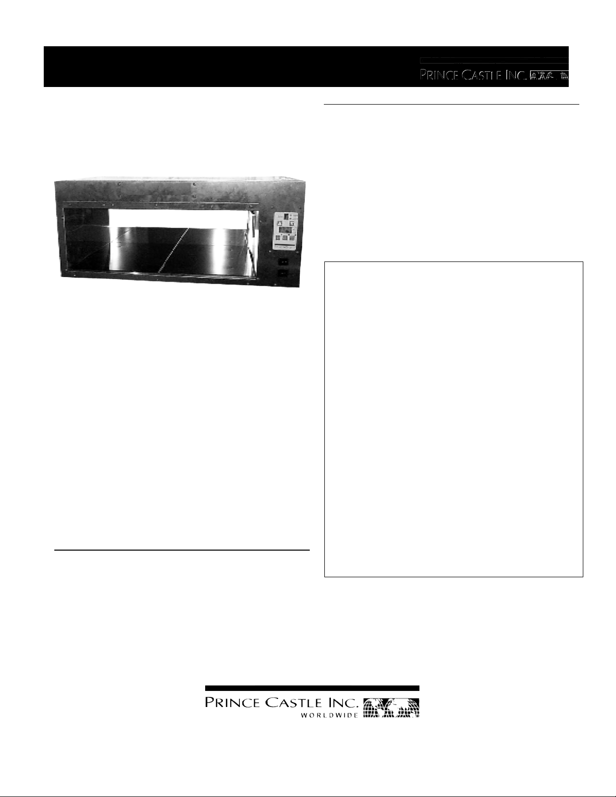
HEATER IDENTIFICATION
AND PROGRAM SET POINT TEMPERATURES
WITH DOORS
1 REAR
107°C
1 FRONT
121°C
3 REAR
121°C
3 FRONT
135°C
2. Verify that all parts have been received.
3. Remove all packaging and fillers. Note: Make
sure that you remove vinyl protective cover from
the stainless steel exterior surfaces and both
sides of the doors before turning on power.
4. Remove Heat Shield (packaged and on top of
Bin) and line up 3 Keyhole slots with studs
above heater compartment and attach.
5. Plug unit into a 230 Volt grounded outlet.
TEMPERATURE CONTROLLER
DHB-KFCCE
The DHB-KFCCE Holding Bin will hold two 18” x 12”
sheet pans. There are top and bottom heaters for
each pan. Each heater has independently controlled
front and rear sections. All heater zones are independently controlled to set point temperatures. The
following is the relationship between the heater
zones and pan location.
2 REAR
82°C
2 FRONT
82°C
figure 2
4 REAR
82°C
4 FRONT
82°C
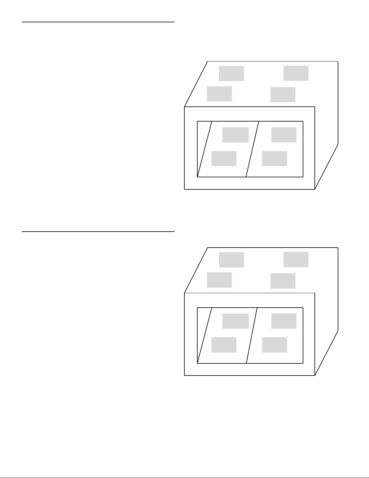
HEATER IDENTIFICATION
AND PROGRAM AND SET POINT TEMPERATURES
WITHOUT DOORS
1 REAR
135°C
1 FRONT
148°C
3 REAR
166°C
3 FRONT
182°C
Heater 1 Front = Left Upper, Front Heat Zone
Heater 1 Rear = Left Upper, Rear Heat Zone
2 REAR
82°C
4 REAR
82°C
Heater 2 Front = Left Lower, Front Heat Zone
Heater 2 Rear = Left Lower, Rear Heat Zone
Heater 3 Front = Right Upper, Front Heat Zone
2 FRONT
82°C
4 FRONT
82°C
Heater 3 Rear = Right Upper, Rear Heat Zone
Heater 4 Front = Right Lower, Front Heat Zone
Heater 4 Rear = Right Lower, Rear Heat Zone
The DHB-KFC has preset temperatures for two
different specifications, one for use with doors
(Figure 1) and one for use without doors (Figure 2).
NOTE: Actual heater surface temperatures will vary
IMPORTANT: Do not program a differential greater
than 16°C between the front and rear heater. See
the explanation in Troubleshooting on page 7 of this
from programmed set point temperature when front
and rear heater set point differential is 11° C or
greater.
manual.
Printed in USA 3/06 © 2006 2 540-507revA
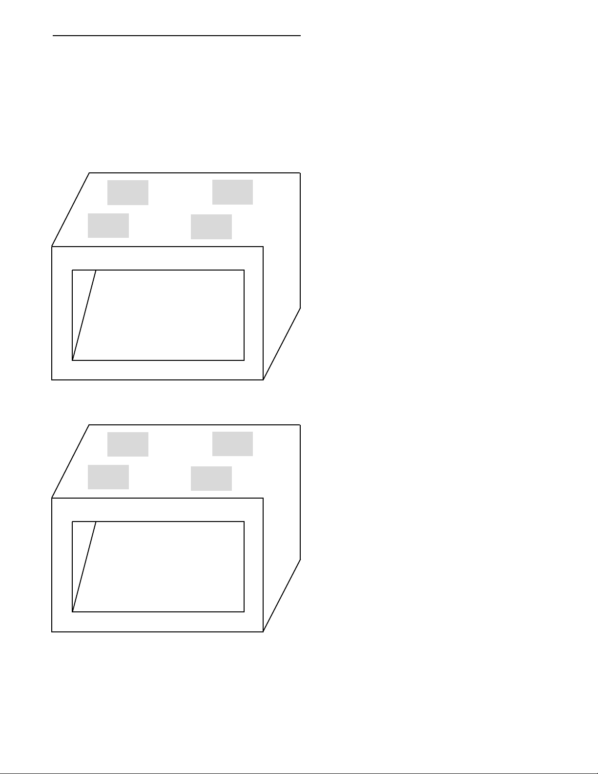
TEMPERATURE CONTROLLER
DHB-KFCGB
Heater 1 Front = Left Upper, Front Heat Zone
Heater 1 Rear = Left Upper, Rear Heat Zone
Heater 3 Front = Right Upper, Front Heat Zone
Heater 3 Rear = Right Upper, Rear Heat Zone
The Temperature Range for heaters 1&3 is 73°C-203°C
HEATER IDENTIFICATION
AND PROGRAM SET POINT TEMPERATURES
WITH DOORS
1 REAR
107°C
1 FRONT
121°C
3 REAR
121°C
3 FRONT
135°C
NO HEATERS
ON BOTTOM
HEATER IDENTIFICATION
AND PROGRAM AND SET POINT TEMPERATURES
WITHOUT DOORS
1 REAR
135°C
3 REAR
166°C
1 FRONT
148°C
3 FRONT
182°C
NO HEATERS
ON BOTTOM
IMPORTANT: Do not program a differential
greater
than 16°C between the front and rear heater. See
the explanation in Troubleshooting on page 8 of this
manual.
NOTE: Actual heater surface temperatures will vary
from programmed set point temperature when front
and rear heater set point differential is 11° C or greater.
540-507revA 3 Printed in USA 3/06 © 2006

OVERLAY PANEL
OVERLAY PANEL BUTTON GLOSSARY
When pressed, will send the unit into the CALIBRATION MODE.
When pressed in conjunction with “Change Set Point” Button will allow the set
point temperature to be changed.
3
203
Displays the currently selected heater and zone (Front or Rear)
Displays the actual temperature for the selected heater zone In Celsius or
Fahrenheight.
In the OPERATION MODE Up and Down Arrows are used for selecting a shelf
heater zone for display purposes. In PROGRAM MODE increase/decrease the
set point value for the current heater being programmed.
In the OPERATION MODE when pressed, display will show the current
temperature for the selected heater zone. In PROGRAM MODE when pressed
will end the program mode.
In the OPERATION MODE when pressed, display will show the current
setpoint temperature for the selected heater zone. In the PROGRAM MODE
when pressed will end the program mode.
When pressed with the PRINCE CASTLE LOGO will allow the
setpoint temperature on the selected heater to be changed.
Printed in USA 3/06 © 2006 4 540-507revA

OPERATION
1. Turn on power switch and light switch located
under control panel
2. Allow 20 minutes for heaters to reach set point
temperatures. For a cold start, the temperature
display will show LLL until the heater temperature reaches 38°C.
Show the Setpoint Temperature for a heater:
1. Press the Up or Down Arrow button until the
heater number and front or rear heater indicator is
selected.
4
NOTE: To set to °F (The unit leaves the factory set in
Celsius) turn the power switch to the “OFF” position.
Press and hold the “UP ARROW” Button then turn
the power switch to the on position, release the “UP
ARROW” 10 seconds after turning on the power. To
switch from °F to °C turn power switch to the “OFF”
position. Press and hold the “DOWN ARROW”
Button then turn the power switch to the on position,
release the “DOWN ARROW” 10 seconds after
turning on the power
L L L
Show the Actual Temperature for a heater:
3 8
2 5 5
2. Press the Set Point button.
PROGRAMMING
Change the Setpoint temperature for a heater:
1. Press the Up or Down Arrow button until the
heater number and front or rear Heater indicator
are selected.
2. Press and hold the hidden button (PRI) behind
the Prince Castle logo and the Change Set Temp
button together for 5 seconds. The LED indicator
for Change Set point will light.
1. Press the Up or Down Arrow button until the
heater number and front or rear heater indicator
is selected.
2. Press the Actual Temp button.
4
1 3 5
540-507revA 5 Printed in USA 3/06 © 2006
3. Use the Up and Down Arrow button to increase or
decrease the setpoint temperature. The heater
can be turned off by pressing the Down Arrow
until the display reads “OFF”.
4. Press CHANGE SET TEMP button to store
change and to return to run mode.
IMPORTANT: Do not program a set point temperature differential greater than 30°F between the front
and rear of any heater assembly.
3
2 5 5

CALIBRATION
Occasionally, there are measured differences between the
restaurant’s temperature meter and what the controller
senses for a heater surface temperature. Part of the
difference is the location of the controller sensor versus
the location where the temperature was measured with
the restaurant’s temperature meter. The calibration mode
is used to adjust the Prince Castle controller to the
restaurant’s meter.
RESET TO FACTORY SETTINGS
To reset all times and temperatures to the factory settings, turn unit off, press and hold the UP
and DOWN ARROW BUTTONS at the same time,
turn unit back on. A “P” will appear in the
display and all times and temperatures will be
reset to the original factory settings.
IMPORTANT: Allow heaters 20 minutes to stabilize before
starting the calibration mode.
1. Press the Up or Down Arrow button until the heater
number and front or rear heater indicator for the heater
to be calibrated are selected.
2. Make an external temperature measurement within
the shelf cavity near the center of the heater surface
using a stand alone temperature meter and probe (not
supplied).
CAUTION: Surface temperatures are HOT!
Use caution when making any temperature
measurements within the heater cavity.
3. Press and hold the PRI in the Prince Castle Logo and
the Actual Temp button for 3 seconds.The decimal
point to the left of the °C symbol will light indicating
the Calibration Mode. The temperature value displayed
on the front panel is the actual heater temperature
sensed by the controller.
4. To clear the calibrated offset value, press the Set
Point button. The display will show the temperature
value the sensing probe is measuring. Use steps 5
through 7 to calibrate the temperature display to the
restaurant’s standalone meter.
CLEANING
CAUTION: This appliance is not water
tight. Do not clean with a Water Jet/Jet
Spray. Do not immerse appliance in
water.
CAUTION: Before unplugging power
cord, make sure power switch is in OFF
position.
1. Unplug Holding Bin from outlet.
2. Allow unit to cool down. (Approximately 15
minutes.)
3. Wipe down with a damp cloth. Do not use a
green scotch bright pad, unapproved cleaner, ice
or water.
1 2 1
Calibration Mode Active
5. Use the Up and Down Arrow button to increase or
decrease the displayed temperature until it matches
the value measured by the standalone meter.
6. When the temperature value displayed on the front
panel is equivalent to the temperature value measured
by the standalone meter, press the hidden Prince
Castle Logo button.
7. The new value will be saved by the controller and
Calibration Mode will end.
Printed in USA 3/06 © 2006 6 540-507revA

EXPLODED VIEW
540-204S
Hinge Kit
w/Hardware
(Pkg. of 2)
540-206
Heat Guard
540-202
Door
540-224S
Heater
Assembly
78-166S
Rocker
Switch
213-202S
Leg W/Screw
(Set of 4)
540-207
Frame
540-105S
Overlay & Brkt
Assy.
540-208
Screen
536-791S
Display
Board
88-639-08S
Light Bulb
(Not Shown)
540-232S (CE)
540-238 (GB)
Power
Board
72-323S
Power Cord
88-683S
Lamp
Socket
540-507revA 7 Printed in USA 3/06 © 2006

TROUBLESHOOTING
The controller incorporates some diagnostic hardware and software to aid in troubleshooting problems. The
display will flash the problem if detected when the heater in question is selected. The error condition will not
display in the Change Set Temp mode.
IMPORTANT: To avoid a possible error message, do not program a differential greater than 30°F between
the front and rear of any heater assembly. The heater with the higher setting may not be able to get up to
temperature because heat will be flowing to the colder heater. An error message will be displayed and the
heater that could not get to temperature will be turned off.
Problem Cause Solution
A. Display flashes Open relay. Replace Power Circuit Board
“Opn” & “rEL” Circuit inoperable
B. Display flashes Shorted relay. Replace Power Circuit Board.
“SHr” & “rEL” Circuit inoperable.
Open heater. Test heater resistance.Replace heater.
Unplugged ribbon cable between Verify ribbon cable connection.
Power and Main Circuit Boards.
C. Display shows “LLL” Temperature is below 75° F N/A
(normal operation)
Display shows “LLL” Heater inoperable. Test heater resistance.Replace heater.
for an extended period Probe inoperable. Check for open thermocouple wires from
of time. probe. Replace heater/probe assembly.
Display shows “LLL” and Circuit inoperable. (see A). See A above.
then changes to “Opn”& “rel”
and heater surface
temperature is cool.
Display shows “LLL” and Circuit inoperable. (see B) See B above.
then changes to “SHr”&“rEL”
and heater surface
temperature is cool.
D.Display shows “HHH” for Temperature is above400° F Diagnostic circuit inoperable. Replace
an extended period of time (abnormal operation) Power Circuit Board.See B above.
and heater surface
temperature is hot.
Display shows “HHH” for Probe is inoperable Check for pinched thermocouple
an extended period of time wires from probe. Replace heater/probe
and heater surface assembly.
temperature is cool.
Note: To reset all times and temperatures to the factory settings, turn unit off, press and hold the UP
and DOWN ARROW BUTTONS at the same time, turn unit back on. A “P” will appear in the display
and all times and temperatures will be reset to the original factory settings.
Printed in USA 3/06 © 2006 8 540-507revA

WIRING DIAGRAM
540-507revA 9 Printed in USA 3/06 © 2006

WIRING DIAGRAM DHB-KFCGB
UPPER RIGHT HEATER
UPPER RIGHT HEATER
Printed in USA 3/06 © 2006 10 540-507revA
 Loading...