

PRESONUS StudioLive AI-Series Owner's Manual
StudioLive
™
AI-Series Mixers
Digital Mixing System with Active Integration
™
Owner’s Manual
www.presonus.com
®
English

Table of Contents
1 Overview — 1
1.1 Introduction — 1
1.2 About This Manual — 2
1.3 Summary of StudioLive AI-series Mixer
Hardware Features — 2
1.4 What is in the Box — 3
2 Getting Started — 4
2.1 Level Setting Procedure — 4
3 Hookup — 9
3.1 Rear-Panel Connections — 9
3.1.1
Installed Option Card — 13
3.2 Front Panel Connections — 13
3.3 Typical Band Setup Diagrams — 14
3.4 Typical Church Setup Diagrams — 16
4 Controls — 18
4.1 The Fat Channel — 18
4.1.1
Select Buttons, Meters,
and the Fat Channel
— 18
4.1.2
Fat Channel Processing Guide — 19
4.1.3
Fat Channel: Dynamics Processing
and EQ
— 19
4.1.4
Sidechaining (32.4.2AI
and 24.4.2AI only)
— 27
4.1.5
A/B Fat Channel Settings — 28
4.1.6
Fat Channel Panning, Stereo Link,
and Link Master
— 29
4.1.7
Fat Channel: Subgroup
and Main Output Assignments
— 29
4.1.8
Copying Fat Channel Settings — 30
4.1.9
Loading Fat Channel Presets — 31
4.1.10
Saving Fat Channel Presets — 32
4.1.11
Channel Presets Library — 34
4.2 Metering — 35
4.2.1
StudioLive Fat Channel
Metering Controls
— 35
4.2.2
Subgroup and Main Meters — 36
4.2.3
A Quick Note About dBu and dBFS — 36
4.3 Input Channel Strip — 37
4.3.1
Input Channel Controls — 37
4.4 Aux and FX Buses — 38
4.4.1
Analog Aux Bus Controls — 38
4.4.2
Internal FX Bus Controls — 39
4.4.3
Aux and FX Bus Channel Sends — 39
4.4.4
Pre/Post Channel Sends — 40
4.4.5
Creating Monitor Mixes — 40
4.4.6
Creating Internal FX Mixes — 41
4.4.7
Using an External Effects Processor — 43
4.5 Subgroups — 45
4.5.1
Subgroup Controls — 45
4.5.2
Creating Instrument Subgroups — 46
4.5.3
Creating Effects Groups — 47
4.6 Main Output Bus — 49
4.7 Mute Groups (StudioLive 32.4.2AI only) — 50
4.7.1
Creating a Mute Group
(StudioLive 32.4.2AI only)
— 51
4.8 Master Section — 51
4.8.1
Aux Inputs A and B — 51
4.8.2
Talkback System — 52
4.8.3
2 Track In — 52
4.9 Solo Bus — 53
4.9.1
Solo Bus Controls — 53
4.9.2
Solo Modes — 54
4.9.3
Solo Clear — 54
4.9.4
Using the Solo Bus for Monitoring — 54
4.9.5
Using Solo in Place (SIP) to
Set Up a Mix
— 55
4.10 Monitor Bus — 57

5 Digital Effects |
Master Control — 59
5.1 Channel Info Page — 59
5.1.1 Customizing Channel
and Bus Names
— 59
5.2 The Digital FX (Effects) Menu — 60
5.2.1
Creating FX Presets — 61
5.2.2
Reverb and its Parameters — 63
5.2.3
Delay and its Parameters — 64
5.2.4
Reverb Effects Preset Library — 65
5.2.5
Delay Effects Preset Library — 65
5.2.6
Digital Effects Types — 66
5.3 Scenes — 67
5.3.1
S1: Zero Out (Board Reset) — 67
5.3.2
Nulling Parameters — 68
5.3.3
Creating a Scene — 68
5.3.4
Scene Recall — 69
5.3.5
Fader Locate — 71
5.3.6
Quick Scenes
(StudioLive 32.4.2AI only)
— 71
5.3.7
AutoStore — 73
5.4 Graphic Equalizers — 73
5.4.1
The GEQ Menu — 74
5.4.2
Saving and Loading
Graphic EQ Presets
— 75
5.5 System Menu — 77
6 Resources — 81
6.1 Stereo Microphone Placement — 81
6.2 Compression Setting Suggestions — 84
6.3 EQ Frequency Guides — 86
6.4 EQ Setting Suggestions — 88
6.5 Technical Specifications — 90
6.6 StudioLive AI Mixers Block Diagrams — 93
6.7 StudioLive 32.4.2AI Recall Sheet — 94
6.8 StudioLive 24.4.2AI Recall Sheet — 96
6.9 StudioLive 16.4.2AI Recall Sheet — 98
7 Troubleshooting
and Warranty — 100
7.1 Troubleshooting — 100
7.2 PreSonus Limited Warranty — 101

iv
1 Overview
1.1 Introduction
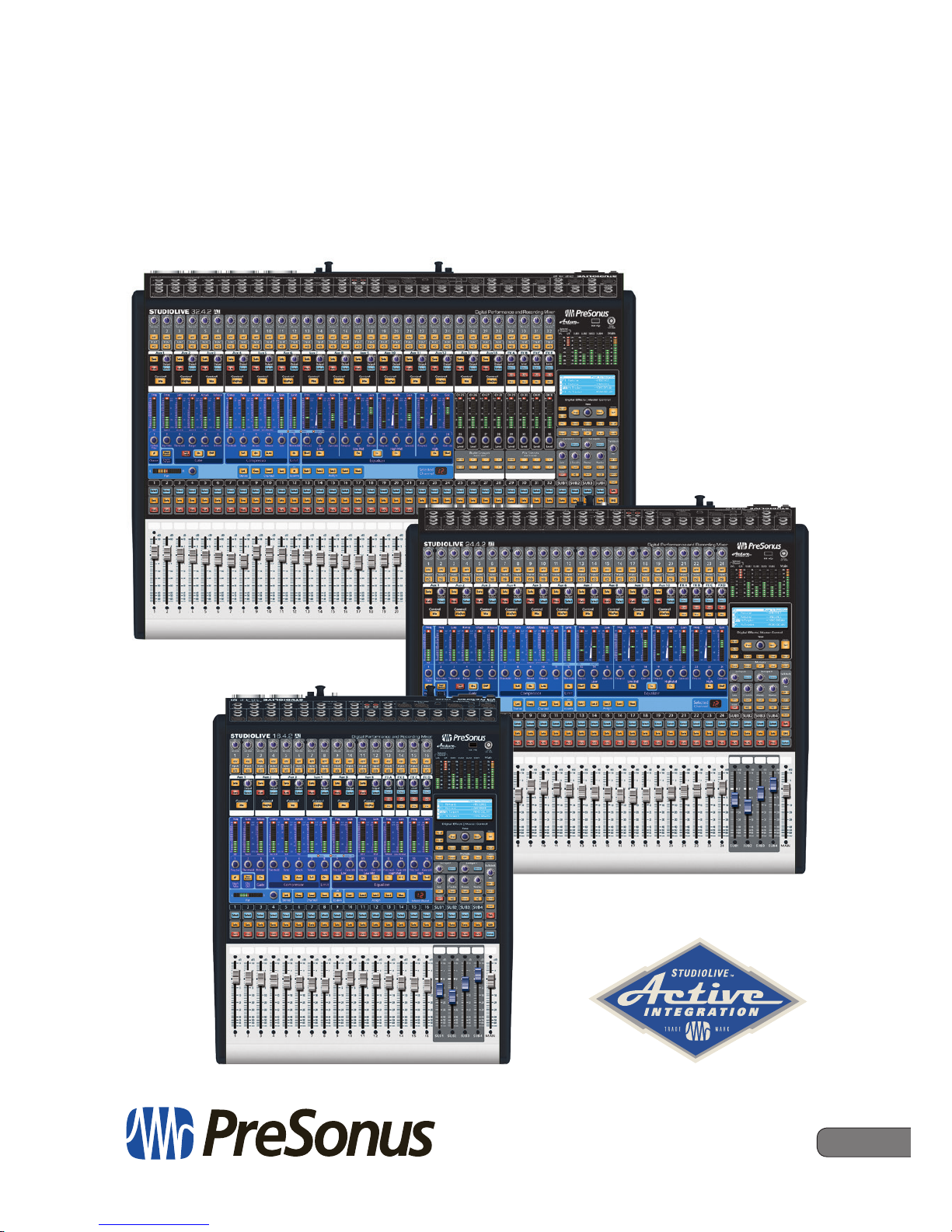
StudioLive™ 32.4.2AI
Owner’s Manual
1
1 Overview
1.1 Introduction
Thank you for purchasing your PreSonus® StudioLive™ AI-series Performance
and Recording Digital Mixer. PreSonus Audio Electronics has designed the
StudioLive utilizing high-grade components to ensure optimum performance that
will last a lifetime. Loaded with 32/24/16 high-headroom, XMAX™ microphone
preamplifiers; a built-in 48x34/40x26/32x18 FireWire s800 recording and playback
interface; Fat Channel processing with 4-band EQs, compressors, limiters, and
expander/gates; reverb and delay effects; 14/10/6 aux buses; 4 subgroups;
extensive LED metering; mixer save/recall; channel-strip save/recall/copy/paste;
talkback; and more, StudioLive breaks new boundaries for music performance
and production. All you need is a compatible computer with a FireWire
connection, a few microphones and cables, speakers, and your instruments,
and you are ready to record in the studio or in front of a live audience!
We encourage you to contact us with questions or comments regarding
this product. PreSonus Audio Electronics is committed to constant
product improvement, and we value your suggestions highly. We believe
the best way to achieve our goal of constant product improvement is by
listening to the real experts: our valued customers. We appreciate the
support you have shown us through the purchase of this product.
For technical support, please see Section 7.1: Troubleshooting.

2
1 Overview
1.2 About This Manual
StudioLive™ 32.4.2AI
Owner’s Manual
1.2 About This Manual
We suggest that you use this manual to familiarize yourself with the features,
applications, and connection procedures for your StudioLive before trying
to connect it to your computer. This will help you avoid problems during
installation and setup. This manual covers hardware functions for all three
StudioLive AI-series mixers. When functional differences are called out,
the 32.4.2AI will be mentioned first, followed by the 24.4.2AI and then
the 16.4.2AI. Note: All illustrated examples use images of the 32.4.2AI.
A separate manual, also included with your StudioLive mixer,
covers the StudioLive AI Software Library, as well as instructions
for connecting and using your StudioLive with a computer.
Throughout this manual you will find Power User Tips. These tips provide mixing
tricks, some of which are unique to the StudioLive, as well as explanations
of various audio terms. In addition, you will find an assortment of audio
tutorials at the back of this manual. These tutorials cover everything from
microphone placement to equalizer and compression-setting suggestions
and are included to help you get the most from your StudioLive mixer.
Thank you, once again, for buying our product. We are
confident that you will enjoy your StudioLive!
1.3 Summary of StudioLive AI-series Mixer Hardware Features
• 24-bit resolution, up to 48 kHz sampling rate
• 32/24/16 Class A XMAX microphone preamplifiers with individual phantom power
• 32/24/16 line-level inputs
• 32/24/16 analog inserts
• 32/24/16 direct outputs
• 2 balanced stereo auxiliary inputs
• Analog stereo tape I/O
• 4 subgroups
• 14/10/6 auxiliary buses
• High-definition AD/DA converters (118 dB dynamic range)
• 32-bit floating point digital mixing and effects processing
• 48x34/40x26/32x18 digital recording interface with
two FireWire s800 (IEEE 1394b) ports
• S/PDIF output
• Optional Thunderbolt and Dante (Ethernet) I/O cards
• Scene automation with load/save/recall of all settings
• Fat Channel with: high-pass filter, gate, compressor, limiter, 4-band parametric EQ
• Alt EQ & Dynamics button lets you A/B two different Fat Channel settings
• USB 2.0 control port supports included USB wireless LAN adapter
• 4 master DSP effects with Load and Save
• 2 with reverb
• 2 with delay
• 6 mute groups with All On/All Off (32.4.2AI only)
• 6 user-assignable Quick Scene Recall buttons (32.4.2 only)
• 31-band graphic EQ on each analog aux and the main bus
• 100 mm faders
• Fast-acting LED meters
3
1 Overview
1.3 Summary of StudioLive AI-series Mixer Hardware Featur es
StudioLive™ 32.4.2AI
Owner’s Manual
• Talkback-communication system
• Windows® and Mac® compatible
• Powerful StudioLive Software Library includes:
• Virtual StudioLive-AI (VSL-AI) advanced editor/librarian/control software
• StudioLive Remote-AI (SL Remote-AI) remote control
app for iPad® (free from Apple App Store)
• QMix™-AI remote aux-mix app for iPhone®/
iPod touch® (free from Apple App Store)
• Capture™ integrated multitrack-recording software
• Studio One® Artist digital audio workstation with more
than 6 GB of plug-ins, loops, and sounds
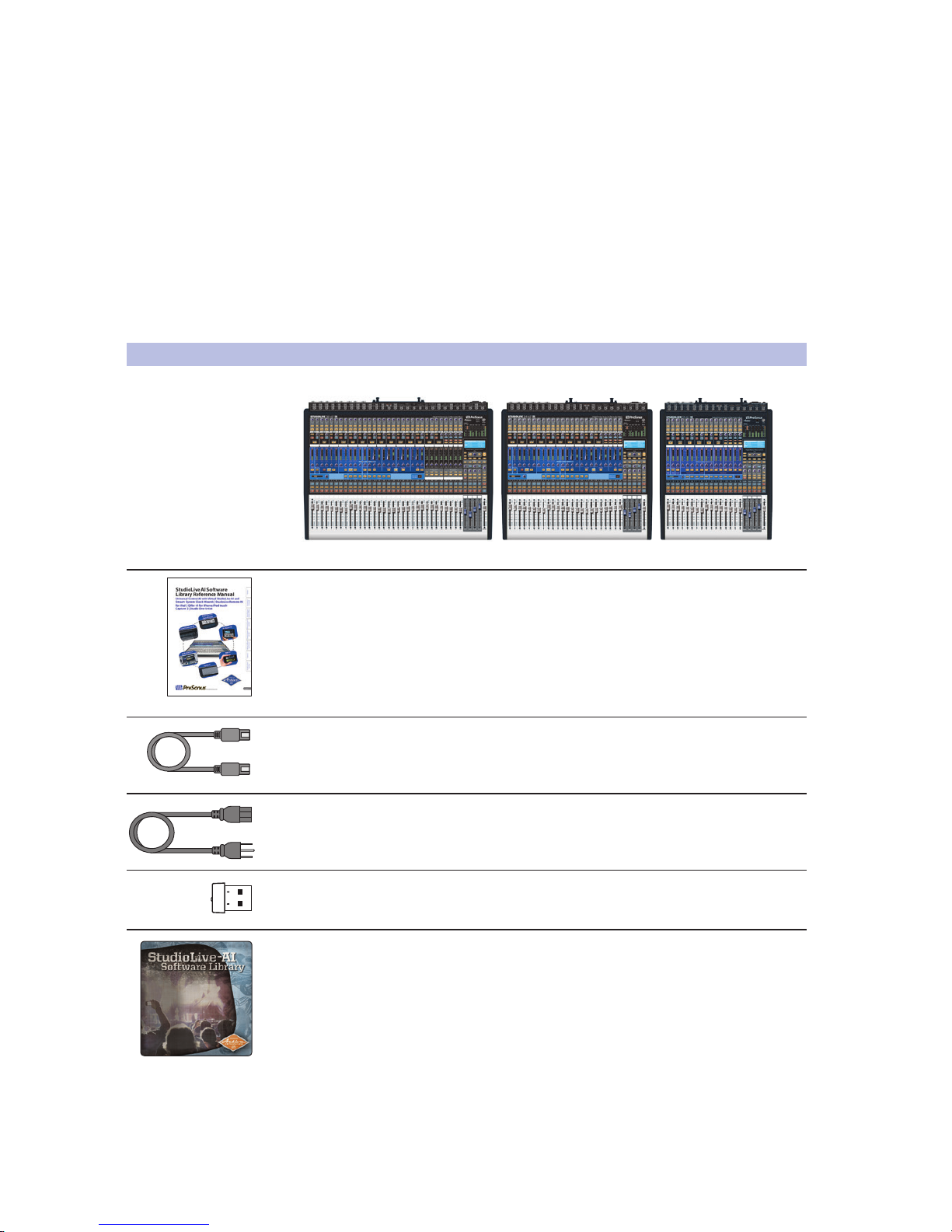
1.4 What is in the Box
In addition to this manual, your StudioLive package contains the following:
• PreSonus StudioLive AI-series digital recording and performance mixer
• StudioLive AI Software Library Reference Manual
• 6-foot (1.8 meter), 9-pin-to-9-pin FireWire s800 cable
• IEC power cord
• USB wireless LAN adapter
• StudioLive Software Library containing:
• PreSonus Studio One Artist program DVD plus
gigabytes of third-party content
• PreSonus Capture CD with demo sessions
• Download instructions for:
- Universal Control AI with VSL-AI
- SL Remote AI for iPad®
- QMix™ AI for iPhone®/iPod® touch
4
2 Getting Started
2.1 Level Setting Procedure
StudioLive™ 32.4.2AI
Owner’s Manual
2 Getting Started
Before you begin, here are a few general rules of thumb:
• Always turn the Main fader and both the Monitor and Phones knobs
in the Monitor section down before making connections.
• Before plugging or unplugging a microphone while other channels
are active, mute the channel to which you are connecting.
• Your faders should be set on or near the “U” mark whenever possible. The “U”
indicates unity gain, meaning the signal is neither boosted nor attenuated. If the
main output of your StudioLive is too high or too low when your faders are at or
near unity, you can use the output-level knob on the rear panel of the StudioLive
to adjust the level up or down until you have achieved the optimal volume.
• Do not allow your inputs to clip. Watch the level meters; when the LEDs near
the Clip mark, the top LED will illuminate, indicating that the analog-to-digital
converters are in danger of being overdriven. Overdriving the converters
will cause digital distortion, which sounds terrible. The XMAX™ preamps
in your StudioLive provide plenty of headroom; take advantage of it.
Your P.A. and studio equipment should be powered on in the following order:
1. Sound sources (keyboards, direct boxes, microphones,
etc.) connected to the StudioLive inputs
2. StudioLive AI mixer
3. Computer (if applicable)
4. Power amplifiers or powered monitors
When it’s time to power down, your system should be turned off in the reverse
order. Now that you know what not to do, let’s get some audio going!
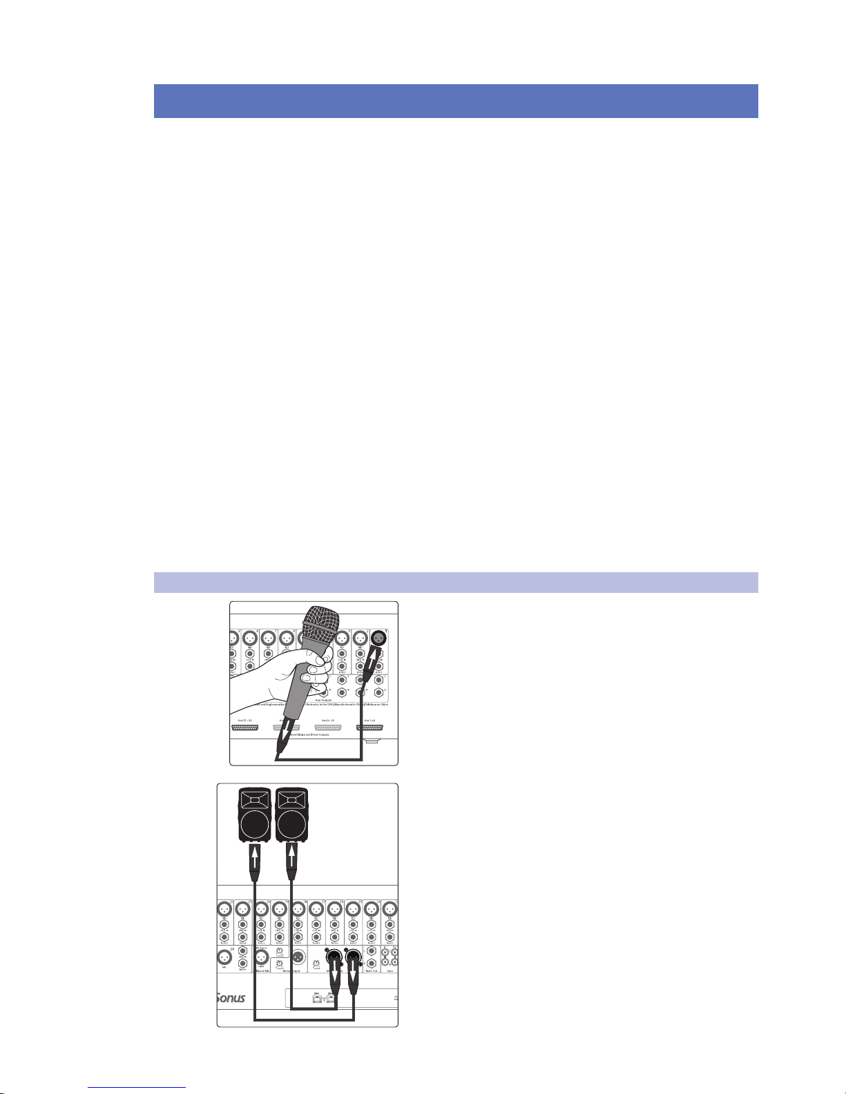
2.1 Level Setting Procedure
1. Grab a microphone and a mic cable and plug them into the
StudioLive’s Channel 1 mic input.
2. Connect the Main outs (TRS or XLR) of your StudioLive to
your power amplifier or powered monitors.
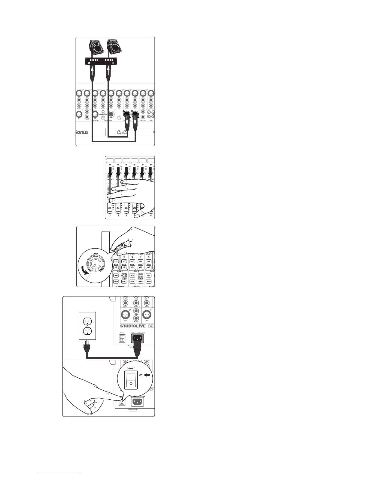
5
2 Getting Started
2.1 Level Setting Procedure
StudioLive™ 32.4.2AI
Owner’s Manual
3. If you’re using passive speakers, connect them to your power
amplifier using speaker cable.
4. Bring down all the faders on your StudioLive to the ∞ setting.
5. Make sure that the Mic/Line knob on Channel 1 is all the way
counter-clockwise.
6. Plug your StudioLive into a power outlet and turn it on.
6
2 Getting Started
2.1 Level Setting Procedure
StudioLive™ 32.4.2AI
Owner’s Manual
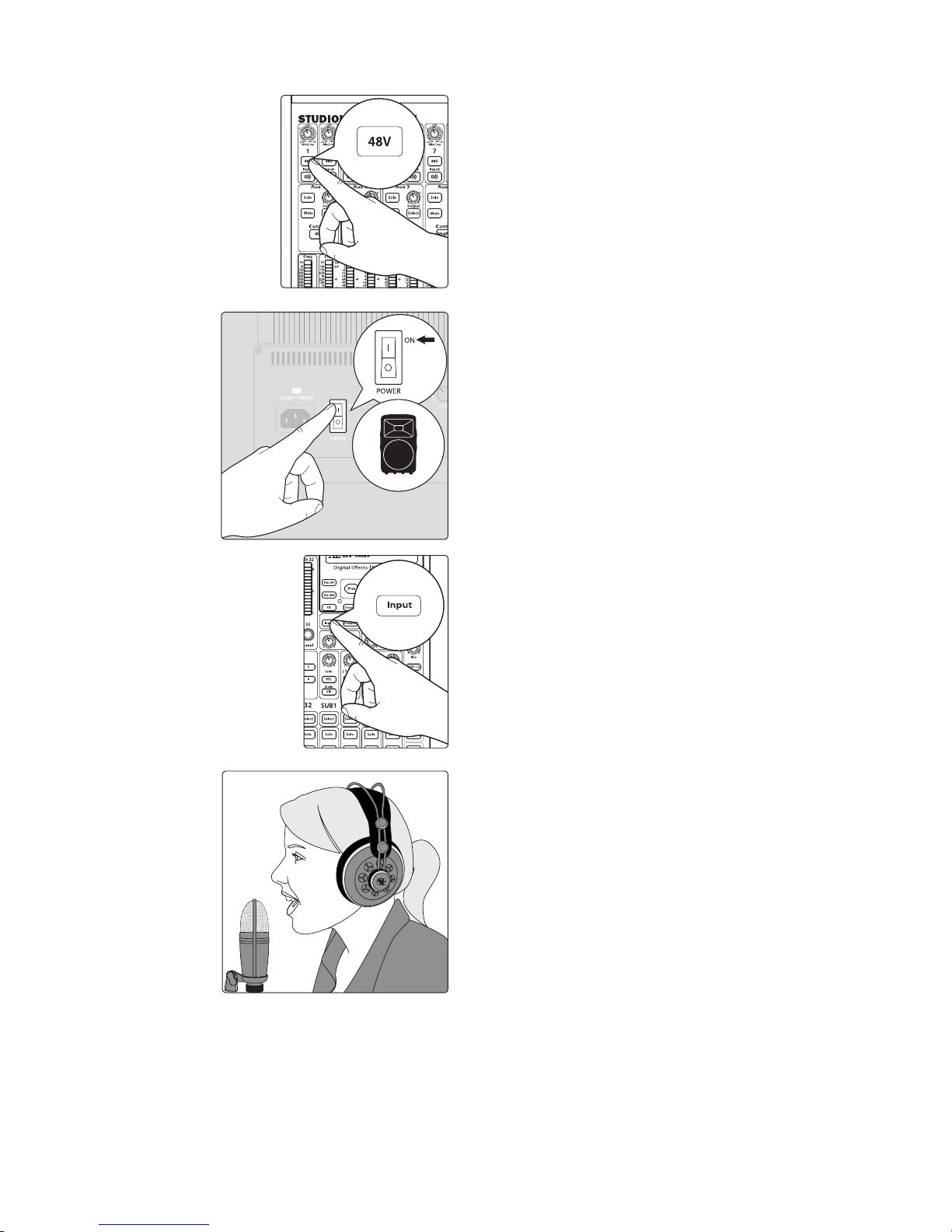
7. If your microphone requires phantom power, engage the 48V
button on Channel 1 of your StudioLive.
8. Turn on your amplifier or powered monitors.
9. Press the Input button in the Meter section.
10. Speak or sing into your microphone at approximately the
same volume you expect during the performance.
7
2 Getting Started
2.1 Level Setting Procedure
StudioLive™ 32.4.2AI
Owner’s Manual
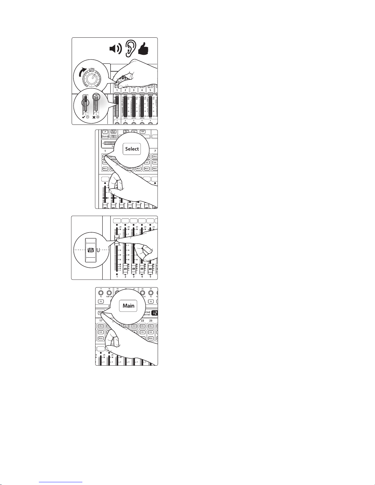
11. Turn the trim knob on Channel 1 clockwise while watching
the first meter in the Fat Channel. Adjust the Channel 1 trim
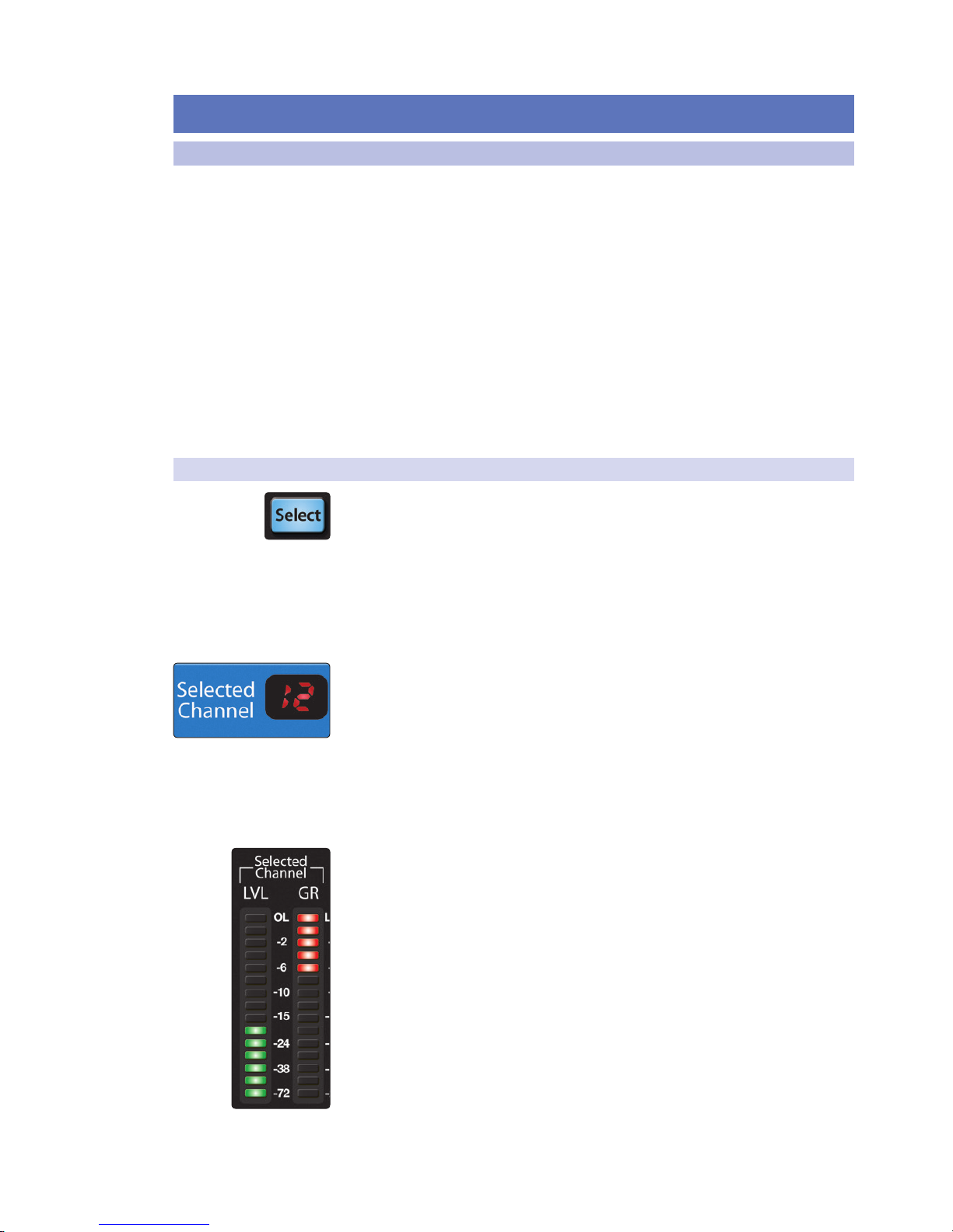
knob until a little more than half of the green LEDs are lit. The
red LED at the top of the meter should never light up.
12. Press the Select button on Channel 1.
13. Raise the Channel 1 fader until it reaches “U” (unity gain).
14. Press the Main button in the Assign section of the Fat
Channel so that it illuminates. This routes the channel to the
main output bus.
8
2 Getting Started
2.1 Level Setting Procedure
StudioLive™ 32.4.2AI
Owner’s Manual
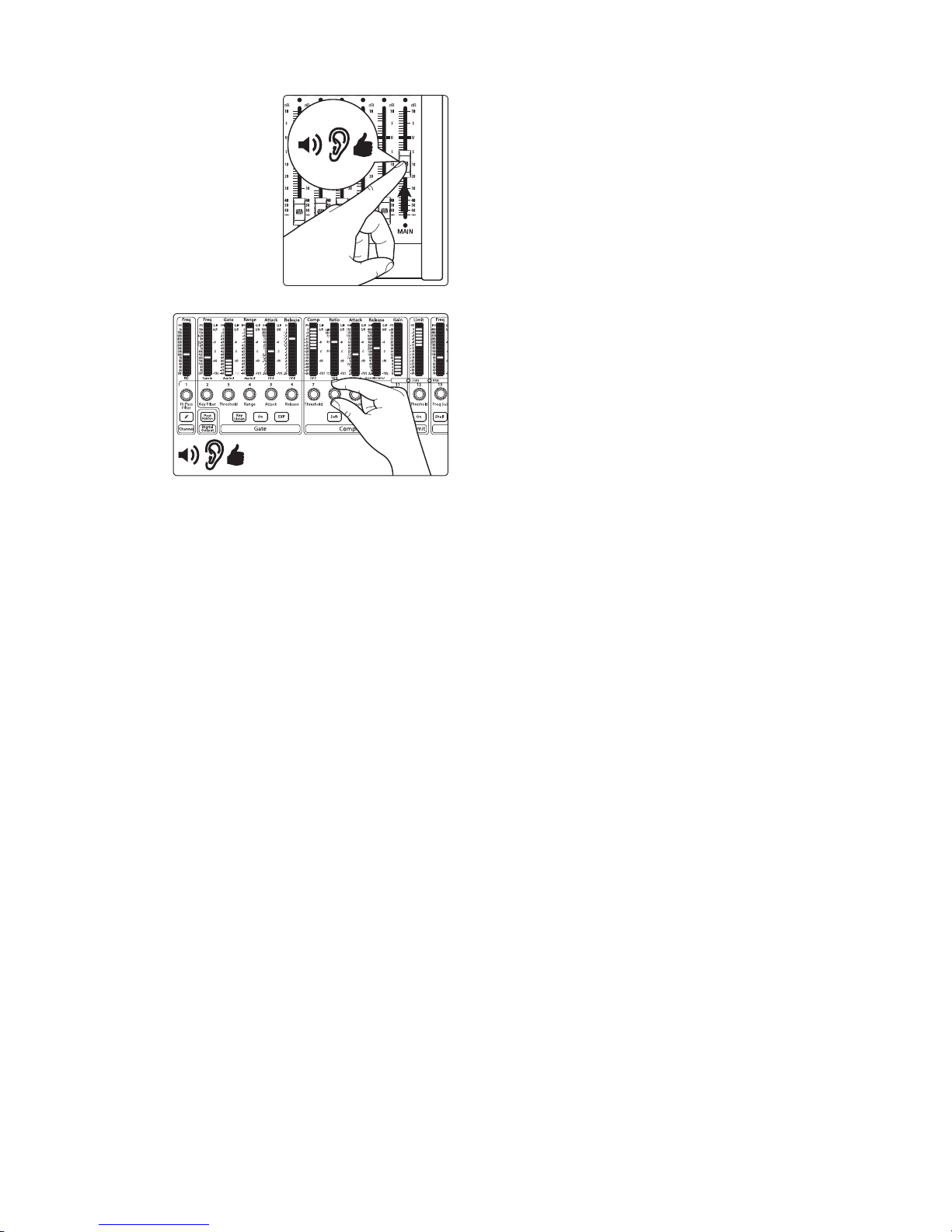
15. Bring up the Main fader until you can comfortably listen to
your microphone through your speakers.
16. With Channel 1 selected, you can use the Fat Channel to add
dynamics processing and EQ.
9
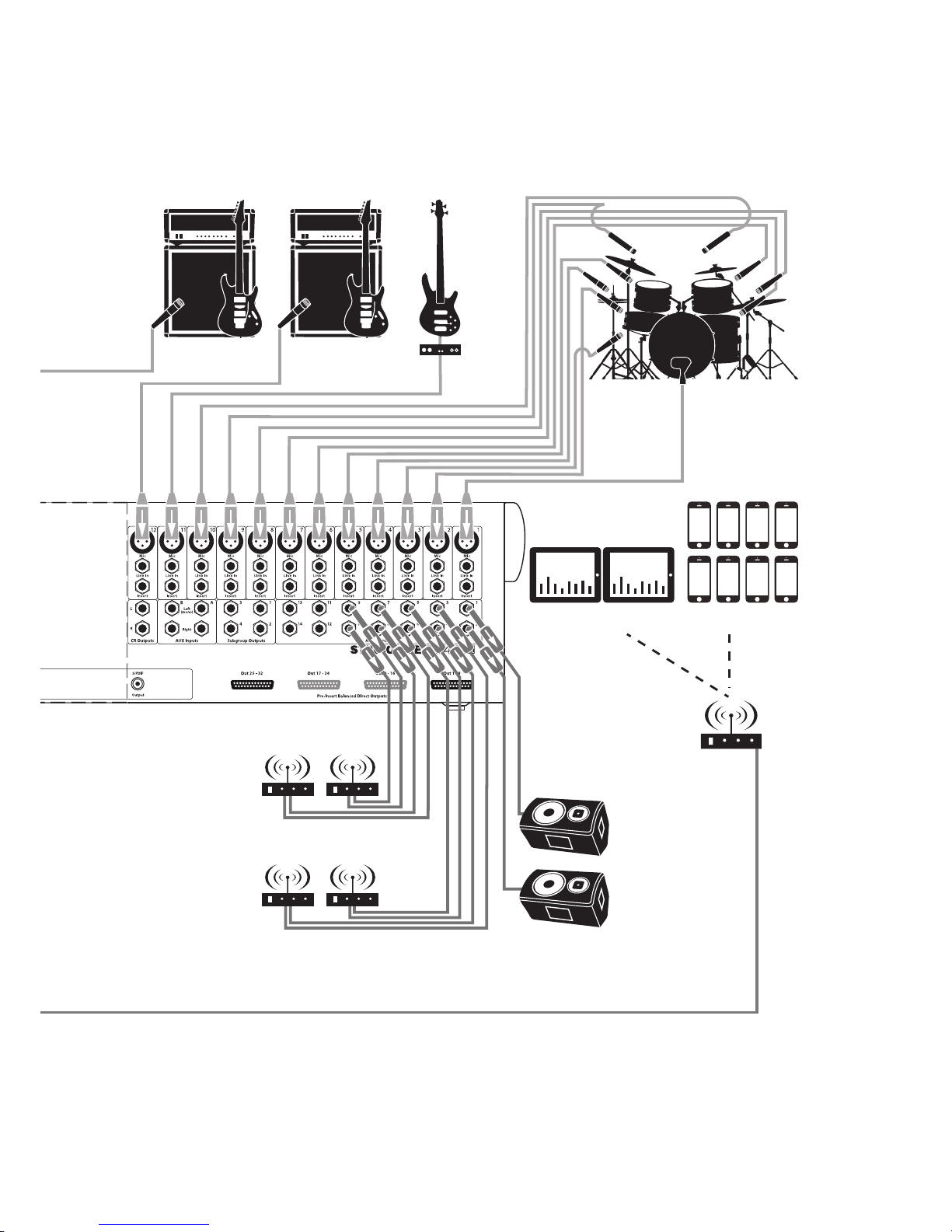
3 Hookup
3.1 Rear-Panel Connections
StudioLive™ 32.4.2AI
Owner’s Manual
3 Hookup
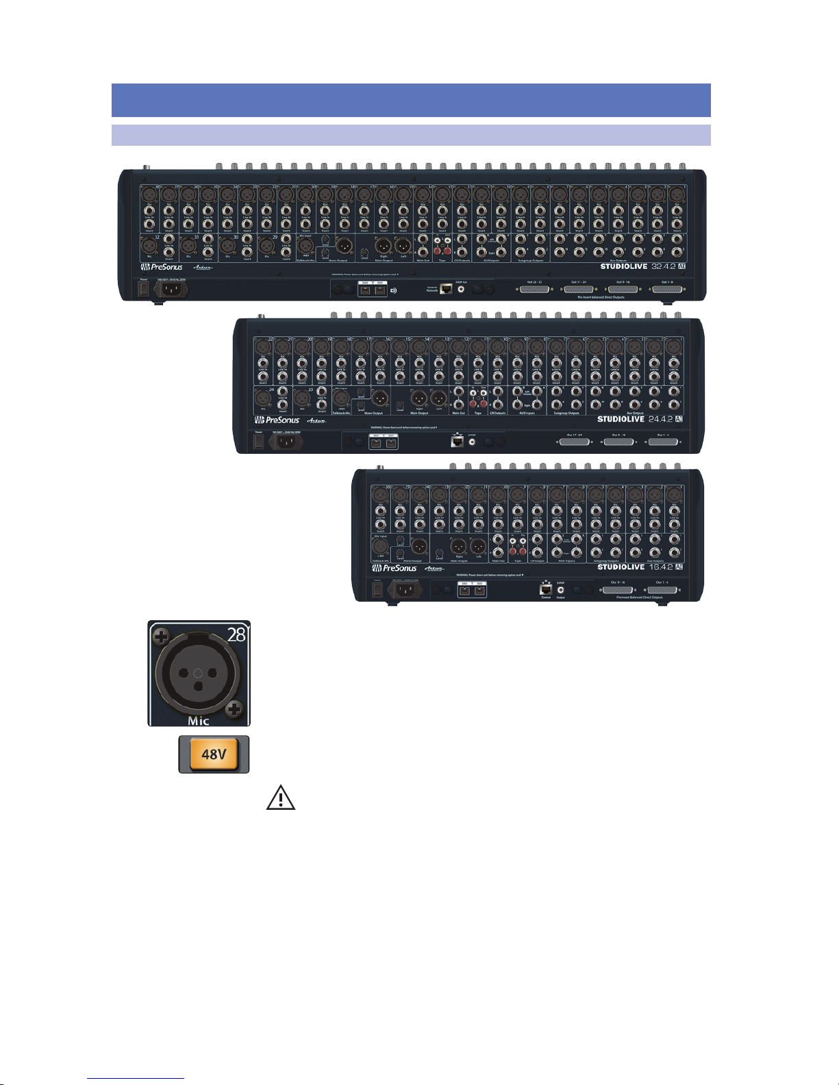
3.1 Rear-Panel Connections
Microphone Inputs. Your StudioLive is equipped with 32/24/16 PreSonus XMAX
microphone preamplifiers for use with all types of microphones. The XMAX
preamplifier has a Class A input buffer, followed by a dual-servo gain stage. This
arrangement results in ultra-low noise and wide gain control, allowing you to boost
signals without increasing unwanted background noise.
48-volt Phantom Power. The StudioLive provides 48V phantom power for the
microphone input on each channel. This feature can be individually enabled for each
channel using buttons on the top panel.
WARNING: Phantom power is required for condenser microphones but can
severely damage some dynamic mics, especially ribbon mics. Therefore, switch
phantom power off for all channels where it is not required.
Power User Tip: Dynamic microphones and ribbon microphones are generally
lower-output devices and require no external power source. The most important
thing to note about ribbon microphones is that they very rarely require phantom
power. In fact, unless a ribbon microphone calls specifically for phantom power,
sending phantom power to it can cause severe damage. Condenser microphones
are generally more sensitive than dynamic and ribbon microphones and typically
require external +48V phantom power. Always review your microphone’s
documentation to ascertain the manufacturer’s recommended operating practices.
XLR connector wiring for phantom power:
Pin 1 = GND Pin 2 = +48V Pin 3 = +48V
10
3 Hookup
3.1 Rear-Panel Connections
StudioLive™ 32.4.2AI
Owner’s Manual
Line-level Inputs. Each channel of the StudioLive has a ¼-inch, balanced TRS
connection for line-level input. When these inputs are engaged, the microphonepreamp circuit is bypassed. Typical examples of line-level connections are synthesizer
outputs, CD/DVD-player outputs, and (with exceptions) signal-processor inputs and
outputs.
Note: As with any mixer, plugging in a microphone or a line-level input device, or
turning phantom power on or off, will create a momentary spike in the audio
output of your StudioLive. Because of this, it is highly recommended that you mute or turn
down the channel trim before changing connections or turning phantom power on or off.
This simple step will add years to life of your audio equipment.
Insert. Each input channel on the StudioLive has a direct-insert point. These
unbalanced, ¼-inch connectors can be used to connect external processors (such as
compressors, EQs, de-essers, and filters) to your StudioLive’s channel inputs. The
insert’s send is after the channel’s gain control but before the digital bus. The return
goes straight to the digital bus. So if you insert a de-esser on your vocalist’s channel,
you will be sending an unprocessed, amplified signal to the de-esser; the processed
signal returned to the StudioLive will then be routed to the digital bus, where it can
be sent through the Fat Channel, Aux and FX buses, etc.
Insert-connector wiring:
Tip = send (output to inserted device)
Ring = return (input from inserted device)
Sleeve = common ground
Aux Inputs. The StudioLive offers two auxiliary inputs. While these line inputs
are generally used as effects returns, they can also be used for any line-level
source (synthesizers, amp modelers, etc.). In Section 4.4.7, we discuss using
an aux bus to send several channels to an external effects processor; the aux
inputs can be used to return the processed signal to the mixer. Each input is
balanced stereo. The left input is normalled to the right input, so if you are
returning a mono signal to the mix, connect it to the left input, and the signal
will be routed to both sides of the mix.
Subgroup Outputs. These are balanced mono outputs for each subgroup.
Tip
(Return)
Tip
(Send)
To mixer
channel
insert
From
processor
output
To
processor
input
Tip
(Out)
Ring (In)
Ring
(Return)
Tip
(Send)
11
3 Hookup
3.1 Rear-Panel Connections
StudioLive™ 32.4.2AI
Owner’s Manual
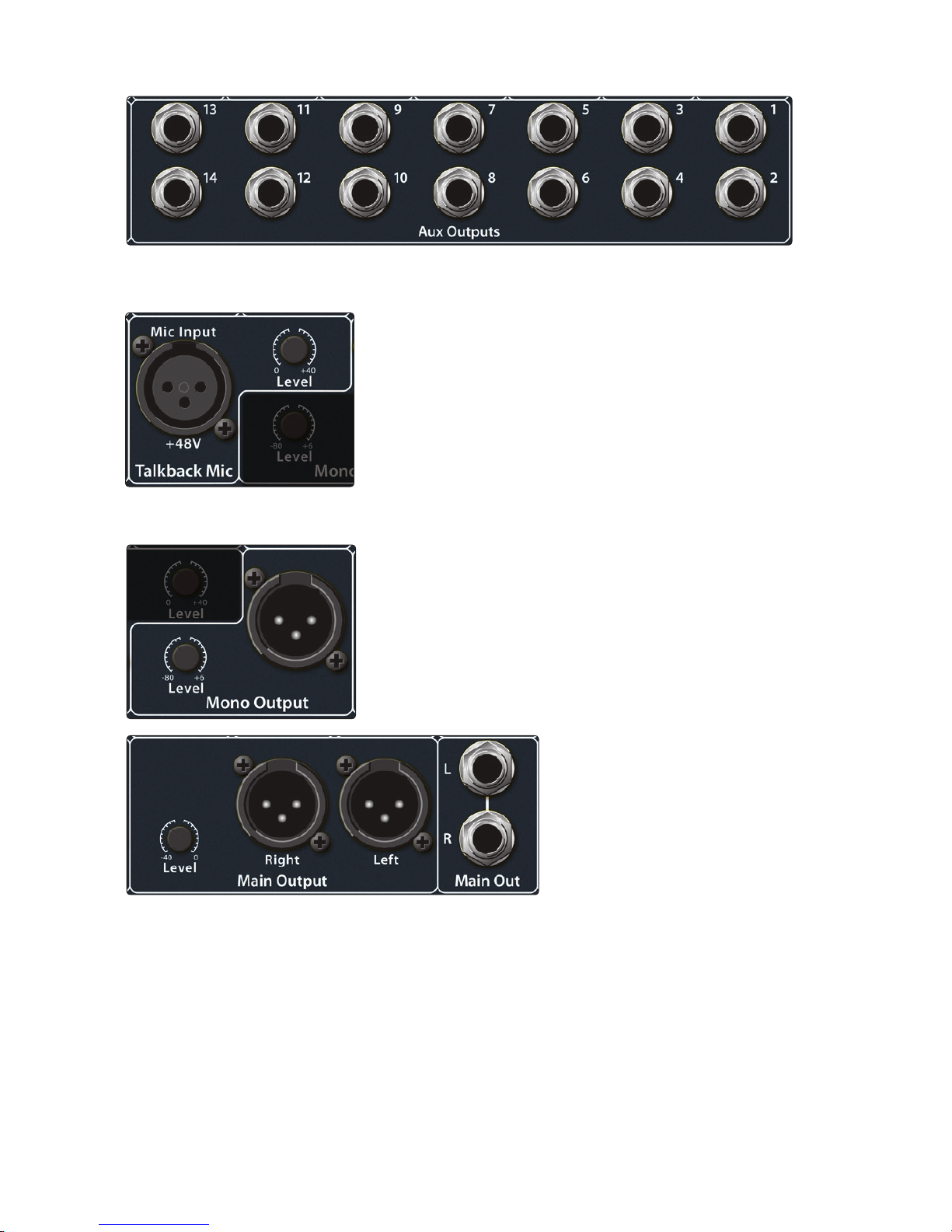
Aux Outputs. The StudioLive is equipped with 14/10/6 auxiliary outputs. Aux mixes
are routed to these outputs. In Section 4.4.5 and 4.4.6, we discuss in detail how to
create aux mixes for monitoring and effects processing.
Talkback Mic Input. The StudioLive does not have an onboard
talkback mic; an external mic must be used. Phantom power is
always enabled on the Talkback microphone preamp, so either a
dynamic or a condenser microphone can be used. However, we
recommend reviewing the documentation that came with your
dynamic microphone to verify that phantom power will not harm it.
Power User Tip: The Talkback microphone preamp is the same high-quality
XMAX preamp that is featured on StudioLive channel mic inputs. The Talkback
input can also be selected as a recording input. See “Auxiliary Digital
Sends” in the StudioLive AI-Series Software Library Manual for details.
Talkback Mic Level. This is the trim control for your talkback microphone.
It adjusts the gain of the talkback input.
Mono Output. This balanced output carries a mono, summed
version of the stereo signal from the Main bus.
Mono Output Level. This knob controls the maximum level of the Mono
Output signal. The signal can be attenuated to -80 dB and boosted up to
+6 dB.
Main Output. The StudioLive features
both XLR and TRS main outputs.
These outputs are parallel to each
other and to the mono output.
Main Output Level. This knob
controls the maximum output level
of the XLR and TRS main outputs.
The signal can be attenuated to
-40 dB and boosted up to 0 dB.
Power User Tip: All StudioLive main outputs (XLR stereo, TRS stereo, and XLR mono)
are active all of the time. Therefore, you can send your main mix to five speakers
at the same time. This can be especially useful when you need to send a mix to
another room or add another set of speakers to accommodate a larger venue.
12
3 Hookup
3.1 Rear-Panel Connections
StudioLive™ 32.4.2AI
Owner’s Manual
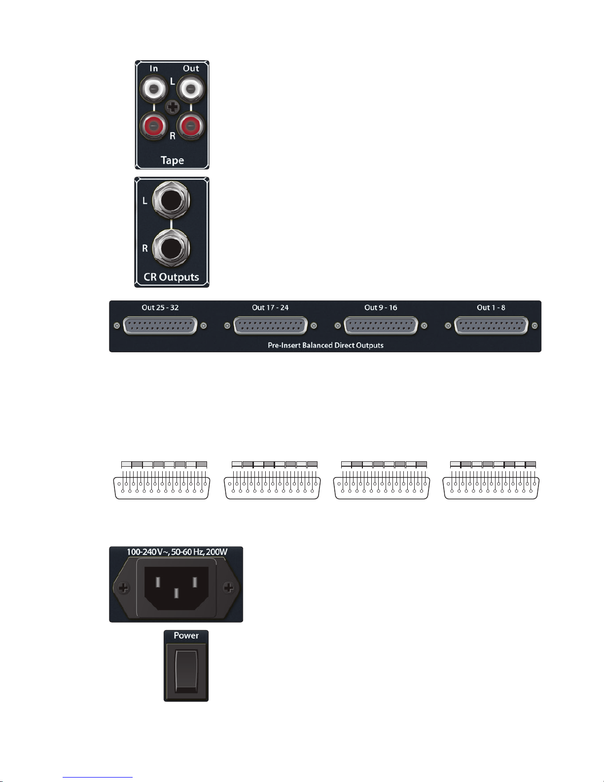
Tape In/Out. The StudioLive is equipped with stereo RCA inputs and outputs that
can be used to connect a tape deck, CD player, or other consumer device. The
tape-input level is controlled by the 2 Track In knob on the top panel. The Main bus is
routed post-fader to the tape output.
CR Output. These are the balanced control-room outputs. The level is controlled by
the Monitor knob in the Monitor section on the top panel.
Pre-Insert Balanced Direct Outputs. These are the balanced, direct
analog outputs for the 32/24/16 channels. The DB25 connectors divide
the channels into groups of eight. Balanced DB25 fan-out snakes can
be obtained in various configurations at most recording and live-sound
retailers. Common fan-outs are DB25 to (8) XLRM and DB25 to (8) TRS.
These outputs are post-gain, pre-insert, and pre-A/D converter. Only the
microphone preamps and line-level inputs are available through the direct
outputs. The digital returns cannot be patched to the direct outputs.
DB25 pin-outs: H = Hot C = Cold G = Ground
Power-cable Input. This is where you plug in the provided IEC power cable.
Power Switch. Push the top part of the switch ( | ) to turn on your StudioLive. Push
the bottom part of the switch ( O ) to turn it off.
13 12 11 10 9 8 7 6 5 4 3 2 1
25 1415161718192021222324
C G H C G H C G H C G HG CHGCHGCHGCH
17 18 19 20 21 22 23 24
13 12 11 10 9 8 7 6 5 4 3 2 1
25 1415161718192021222324
C G H C G H C G H C G HG CHGCHGCHGCH
1 2 3 4 5 6 7 8
13 12 11 10 9 8 7 6 5 4 3 2 1
25 1415161718192021222324
C G H C G H C G H C G HG CHGCHGCHGCH
9 10 11 12 13 14 15 16
Pre-Insert Balanced Direct Outputs
13 12 11 10 9 8 7 6 5 4 3 2 1
25 1415161718192021222324
C G H C G H C G H C G HG CHGCHGCHGCH
25 26 27 28 29 30 31 32
13
3 Hookup
3.2 Front Panel Connections
StudioLive™ 32.4.2AI
Owner’s Manual
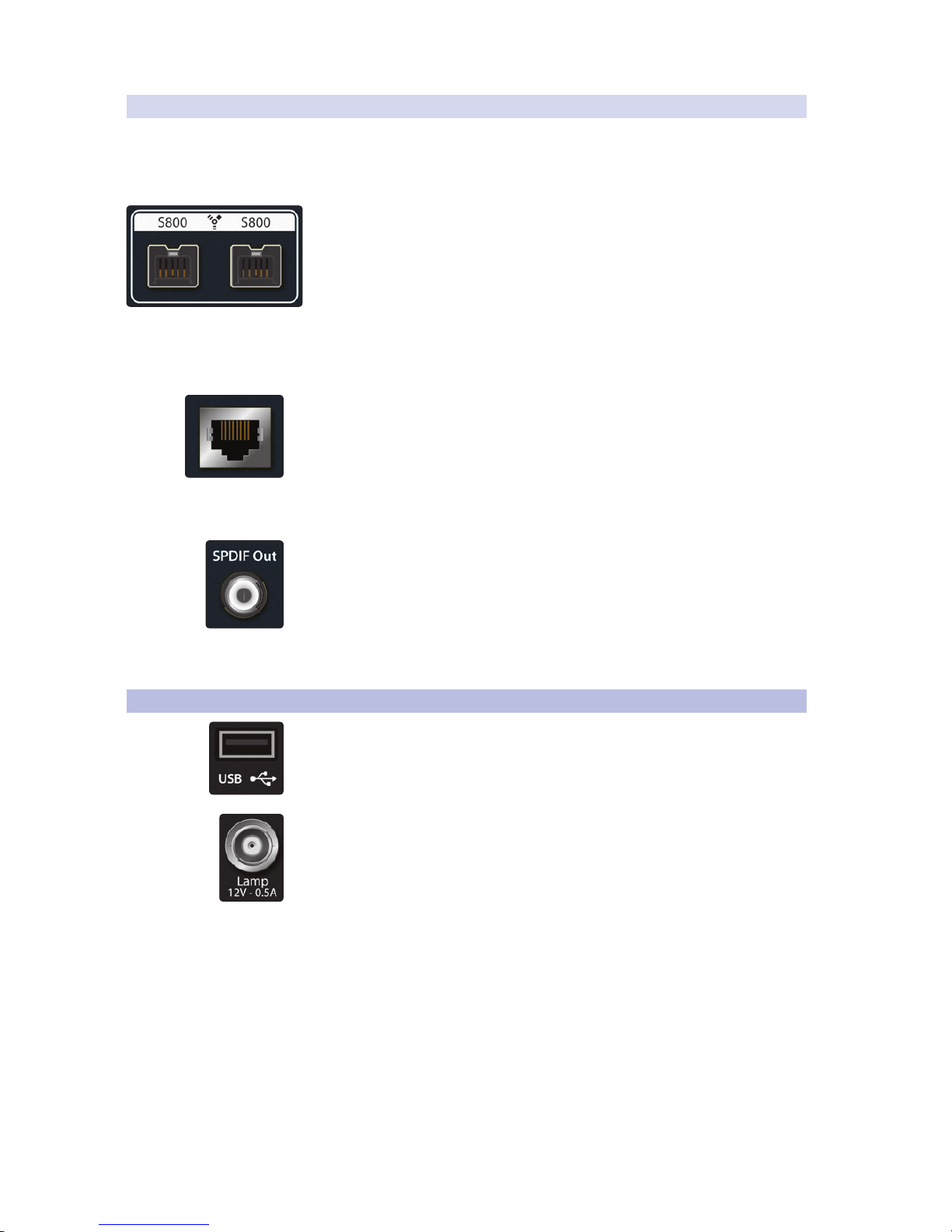
3.1.1 Installed Option Card
Each StudioLive AI-series mixer includes an installed option card that provides
FireWire s800 connectivity, Ethernet for remote control, and S/PDIF output. For more
information about user-installable StudioLive AI-series mixer option cards and their
availability, please visit www.presonus.com.
FireWire s800 Ports. There are two standard 9-pin FireWire s800 ports on the
back of the StudioLive. Either port can be used to connect the StudioLive to
a FireWire s800 port on your computer. Use the second FireWire s800 port to
connect additional s800 devices (such as external hard drives) to your computer.
Please note: While connecting your StudioLive AI-series mixer to a FireWire 400
connection on your computer and daisy-chaining a FireWire 400 device to the
secondary s800 port are supported, this will reduce your StudioLive bus speed to
400 Mbps, and you may experience reduced performance. To experience the full
power of your StudioLive AI-series mixer, it is highly recommended that you connect
to a true s800 connection or to a Thunderbolt connection using an adapter.
Ethernet. This standard RJ45 connection has been included to hardwire your
StudioLive to a LAN network. By adding a wireless router to the network, you will be
able to wirelessly remote control your StudioLive from virtually anywhere. This is
especially useful when your wireless control devices (iPad, iPhone, or iPod touch)
must be used in a different room from where your StudioLive is installed, or if there is
quite a bit of wireless interference in your venue. For more information on
connecting your StudioLive to a LAN network, please review “Networking your
StudioLive Mixer” in the StudioLive AI-Series Software Library Manual.
S/PDIF Output. By default, the S/PDIF output receives the same signal as the main
outputs, so no activation is necessary. However, any bus can be routed to the S/PDIF
output, either through the System menu in the Digital Effects | Master Control
section, or in VSL-AI. (See Section 5.5 in this manual or “VSL-AI: Setup Tab” in the
StudioLive AI-Series Software Library Manual for more information.) Because the
StudioLive cannot be synced externally, you will need to use it as the master clock
and set your S/PDIF-equipped device to receive word clock externally via S/PDIF.
Please consult the documentation for your external digital device for instructions.
3.2 Front Panel Connections
USB. The USB port is for use with the included USB Wi-Fi module. This module will
allow you to connect your StudioLive AI-series mixer to a wireless network and
remote control it using VSL-AI, SL Remote-AI, and QMix-AI. More information about
wireless networking can be found in “Networking your StudioLive Mixer” in the
StudioLive AI-Series Software Library Manual.
This 12V BNC connection is provided to connect a third-party console lamp. Do not
use a bulb that is larger than 6W.
14
3 Hookup
3.3 Typical Band Setup Diagrams
StudioLive™ 32.4.2AI
Owner’s Manual
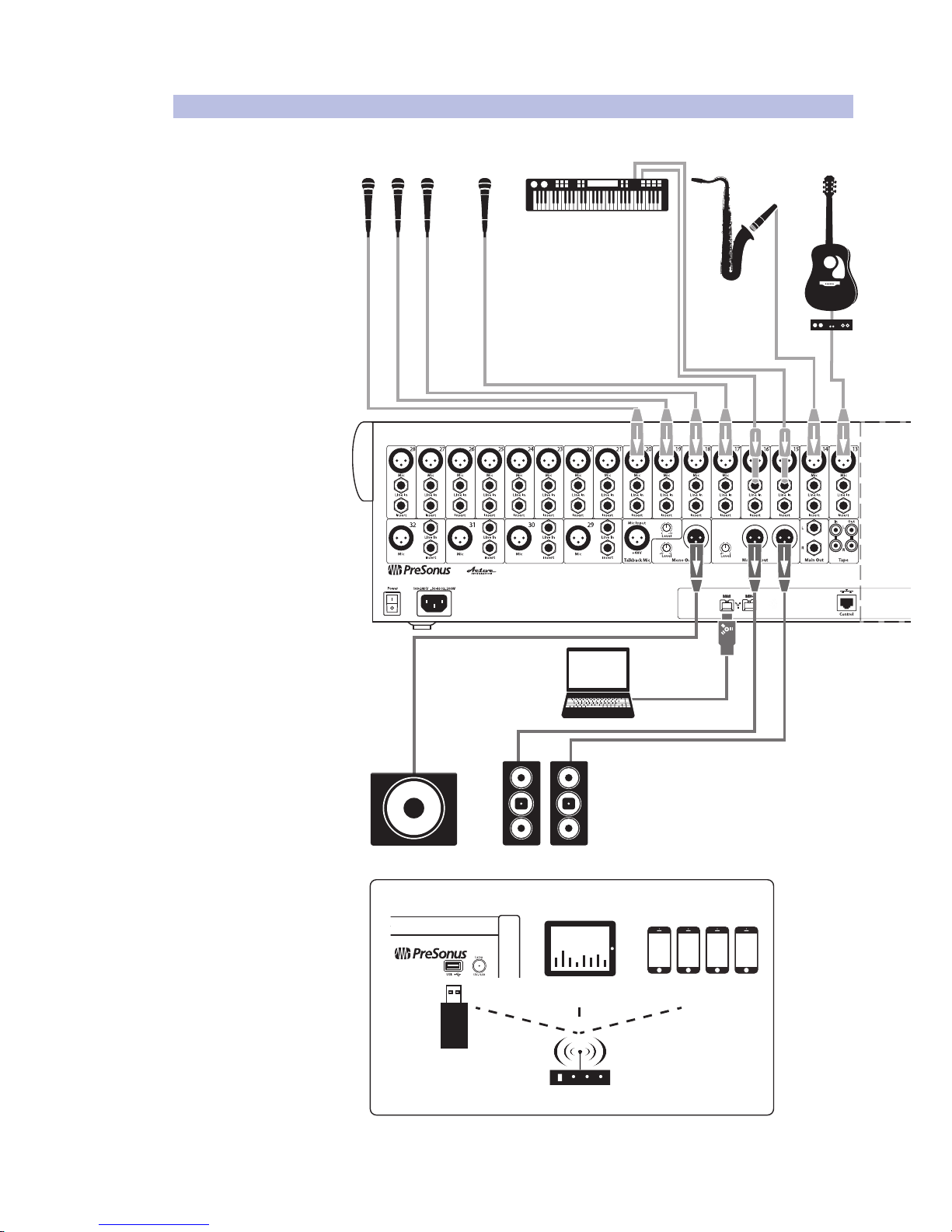
3.3 Typical Band Setup Diagrams
WARNING: Power down unit before removing option card
front of house
speakers
laptop running
Capture 2.0
subwoofer
wireless in-ear
(keys)
wireless in-ear
(lead vocals)
sidelldrum monitor
wireless router
StudioLive control surface
iPad running
SL Remote-AI
USB Wireless
LAN adapter
iPhones running QMix-AI
WIFI
acoustic
guitar/DI
sax
keyboard/DI
lead vocal
backup vocal mics
bass/DI
electric guitar amp
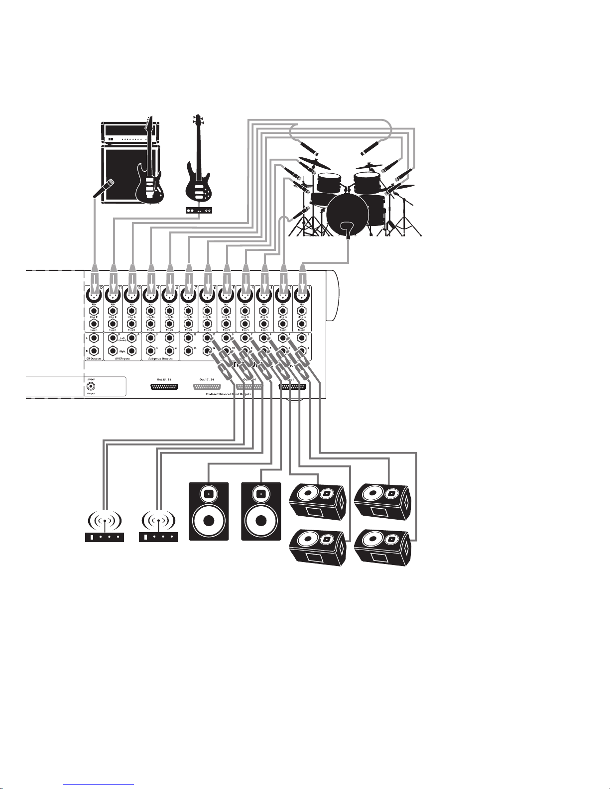
15
3 Hookup
3.3 Typical Band Setup Diagrams
StudioLive™ 32.4.2AI
Owner’s Manual
wireless in-ear
(keys)
wireless in-ear
(lead vocals)
oor wedges
sidelldrum monitor
drum kit
bass/DIelectric guitar amp
16
3 Hookup
3.4 Typical Church Setup Diagrams
StudioLive™ 32.4.2AI
Owner’s Manual
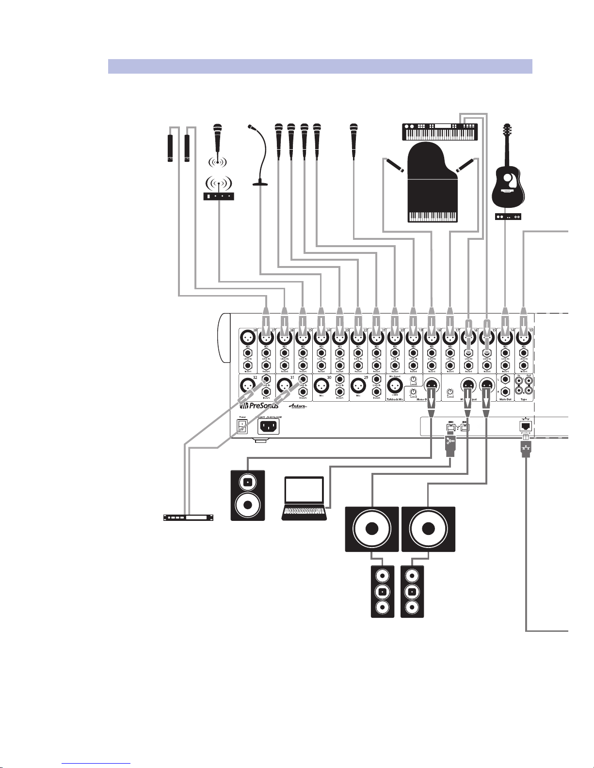
3.4 Typical Church Setup Diagrams
dvd player
keyboard/DI
piano
lead vocalbackup vocal mics
podium
mic
hanging
choir mics
acoustic
guitar/DI
electric guitar
amp (rhythm)
electric guitar
amp (lead)
wireless in-ear
(lead guitar)
wireless in-ear
(bass)
wireless in-ear
(keys)
wireless in-ear
(lead vocals)
WARNING: Power down unit before removing option card
front of house
speakers
laptop running
Capture 2.0
cry room
subwoofers
17
3 Hookup
3.4 Typical Church Setup Diagrams
StudioLive™ 32.4.2AI
Owner’s Manual
wireless
router
iPads running
SL Remote-AI
iPhones running QMix-AI
drum kit
bass/DI
electric guitar
amp (rhythm)
electric guitar
amp (lead)
floor wedges
wireless in-ear
(lead guitar)
wireless in-ear
(bass)
wireless in-ear
(keys)
wireless in-ear
(lead vocals)
18
4 Controls
4.1 The Fat Channel
StudioLive™ 32.4.2AI
Owner’s Manual
4 Controls
4.1 The Fat Channel
The revolutionary Fat Channel is the heart of the StudioLive. The Fat Channel
makes dynamics, routing, and panning for every input and output on the
StudioLive available at the touch of a Select button. The 32/24/16 multipurpose
knobs and meters located in the Fat Channel control nearly every adjustment
you will need to make on your StudioLive. From the Fat Channel, you can:
• Add dynamics processing and EQ to every input and output and A/B them
• Create sends and effects mixes for every analog aux bus and internal effects buses
• Assign subgroup and main routing
• Meter inputs, post-dynamics-processing outputs, and
gain reduction for every input channel
• Meter aux-send outputs
• Copy, save, and load mix scenes
• Recall your fader position for stored mixes
4.1.1 Select Buttons, Meters, and the Fat Channel
Select Buttons. All around the StudioLive, you will see Select buttons. There is a
Select button on each of the input channels, each of the analog aux buses, all of the
internal FX (effects) buses, each of the subgroups, both auxiliary inputs, and the main
output bus. Each of these buttons serves exactly the same purpose: to access the
available Fat Channel parameters for its channel or bus.
It should be noted that while the noise gate, compressor, EQ, and
limiter are available on every input channel and bus, the high-pass
filter is only available on the input channels, aux buses, and internal FX
buses, and Polarity Invert is only available on the input channels.
Selected Channel Display. In the lower right corner of the Fat Channel, you will find
an LED readout. The currently selected channel will always be displayed here.
• Input Channels: Channel number
• Subgroup: S1-S4
• Aux Outputs: A1-A9, AA-AE
• FX Buses A-D: FA-FD
• Auxiliary Input A and B: RA and RB
• Main Bus: MA
Selected Channel Meters. In addition, two meters—part of a set of eight meters
located in the top right section of the mixer—are dedicated to displaying
information about the currently selected channel. The meter on the far left of this
section displays the pre-fader input level for the selected channel. The meter to the
right of it displays the gain reduction applied to the selected channel. It is important
to mention that these meters are only active when one of the input channels or an
aux bus is selected.
19
4 Controls
4.1 The Fat Channel
StudioLive™ 32.4.2AI
Owner’s Manual
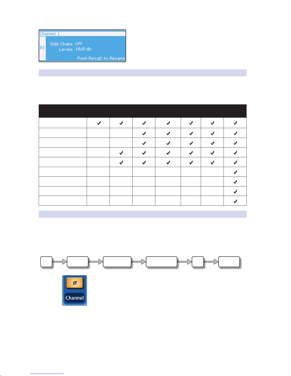
Channel Info Page. When a channel or output bus is
selected, the Channel Info page will open in the LCD. This is
the default screen for your StudioLive. From this page you
can customize the name for each channel or bus and view
helpful information about each channel and bus on your
StudioLive mixer. See Section 5.1 for more information.
4.1.2 Fat Channel Processing Guide
The following table provides a quick guide to the processing that is available
for each bus in the StudioLive. Note that all of these inputs and buses can
be recorded. For more information on digital sends, please see “Digital
Sends and Returns” in the StudioLive AI-Series Software Library Manual.
Bus Phase
Reverse
High-Pass
Filter
Noise
Gate
Compressor EQ Limiter Digital
Send
Inputs Channels
Subgroups
Main Out L/R
Aux Buses
FX Buses
Auxiliary Stereo Inputs
Tape Input
Talkback Mic
Solo Bus
4.1.3 Fat Channel: Dynamics Processing and EQ
The main function of the Fat Channel is to provide dynamics processing and
filtering for every input and output on the StudioLive. The rotary encoders work in
conjunction with the meters directly above them to adjust and display the dynamics
processing and EQ parameters. The Fat Channel’s processing section consists of
five parts: high-pass filter, noise gate, compressor, limiter, and parametric EQ. Each
can be turned on or off and controlled separately. The signal flows as follows:
Polarity Invert. Push this button to invert the polarity of the selected channel’s
signal (that is, to alter the polarity by 180°). The button will illuminate, indicating that
Polarity Invert is active. The Polarity Invert button can be used to correct audio signals
that are out of phase and are canceling/reinforcing each other.
Power User Tip: When recording with more than one open microphone, use
the polarity invert to combat phase cancellation between microphones.
Polarity Invert is only available on the 32/24/16 channels of the input bus.
Hi-Pass LimiterEQØ Noise Gate Compressor
20
4 Controls
4.1 The Fat Channel
StudioLive™ 32.4.2AI
Owner’s Manual
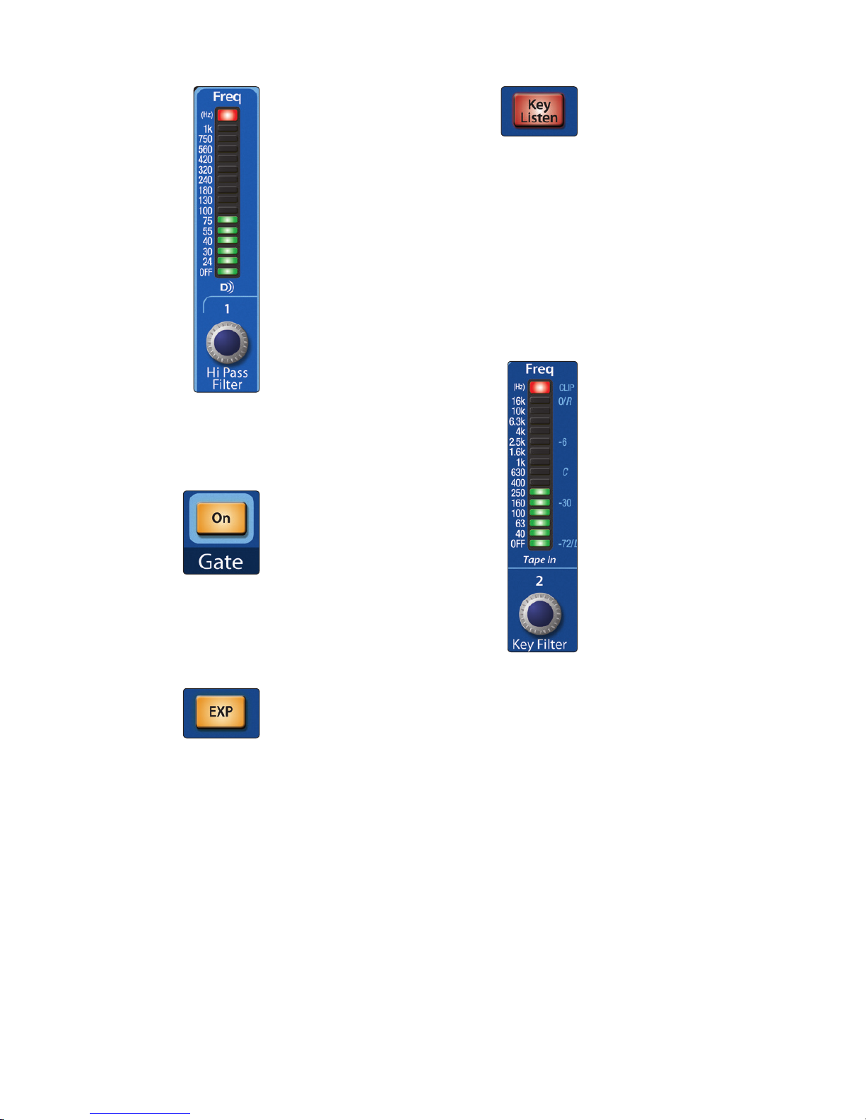
High Pass Filter. Sets the
High-Pass Filter Frequency
Threshold for the Selected
Channel or Output Bus.
The High Pass Filter section
consists of an encoder and
a meter. Frequency range is
indicated to the left of the meter.
The filter’s threshold can be set
from 24 Hz to 1 kHz. When the
meter is set to its lowest point,
the filter is off. The high-pass
filter’s slope is -6 dB/octave.
Power User Tip: A high-pass
filter attenuates all frequencies
below the set threshold. Use the
Fat Channel high-pass filter to
remove unwanted low-frequencies
from your source signal, rather
than trying to EQ them out.
The high-pass filter is available
on the 32/24/16 channels of the
input bus and on every analog
aux and internal FX bus.
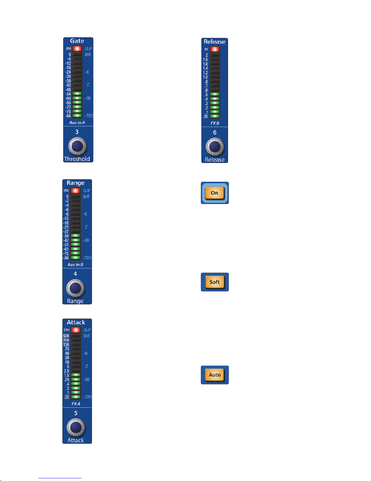
Gate On/Off Button. Turns the
Gate On and Off for the Selected
Channel.
This button engages and
disengages the gate for
the selected channel. It will
illuminate to indicate that
the gate has been enabled.
The gate is available for all
32/24/16 input channels
and every output bus.
Gate Expander Button
(32.4.2AI and 24.4.2AI only).
Turns the Noise Gate into an
Expander.
The StudioLive allows you to
choose between an expander
and a noise gate for each
channel or output. By default, the
Expander button will be enabled.
Power User Tip: In practice,
expanders and noise gates are
used almost identically. The main
difference is that an expander is
smoother and more gradual, so
that it is easier to set the attack and
release times correctly.
Gate Key Listen Button
(32.4.2AI and 24.4.2AI only).
Enables Key Listen in the Solo Bus.
This button engages and
disengages the Key Listen
function in the solo bus. It
will illuminate to indicate that
the Key Listen is active. When
Key Listen is enabled, and the
selected channel is soloed,
you can use the Control Room
outputs to monitor what the
gate key filter is removing.
Press and hold this button to
set a sidechain to the key filter.
See Section 4.1.4 for details.
Gate Key Filter (32.4.2AI and
24.4.2AI only). Sets and Displays
the Frequency at Which the Gate
Will Open.
This encoder sets, and the meter
displays, the frequency at which
the gate will open. Setting a
specific frequency, in addition
to a specific decibel level,
provides more sonic shaping.
The key filter can be triggered by
the selected channel or bus’s signal
or by sidechaining a channel and
using its signal as the source. See
Section 4.1.4 for more information
on using a sidechain with the gate.
Power User Tip: A properly set key
filter on a gate can greatly improve
the overall sound quality of a mix.
For example, if you are inserting
a gate on a snare-drum mic, you
may get enough bleed from the kick
drum to open the gate. This is where
a key filter can come in handy. By
setting the key filter to remove some
of those low frequencies, the gate
won’t be as apt to open for the kick
drum.
21
4 Controls
4.1 The Fat Channel
StudioLive™ 32.4.2AI
Owner’s Manual
Gate Threshold. Sets and Displays
the Threshold of the Gate for the
Selected Channel.
This encoder sets, and the meter
displays, the gate threshold for
the selected channel. The gate
threshold sets the level at which
the gate opens. Essentially, all
signals above the threshold
setting are passed through
unaffected, whereas signals below
the threshold setting are reduced
in level by the amount set by the
range control. If the threshold
is set fully counterclockwise,
the gate is turned off (always
open), allowing all signals to pass
through unaffected. You can set
the threshold from 0 to -84 dB.
Gate Range
(32.4.2AI and
24.4.2AI only)
. Sets and Displays
the Range of the Gate.
This encoder sets, and the
meter displays, the amount
of gain reduction that the
gate will produce. The range
can be set from 0 to -84 dB.
Range control is not available
when using the expander.
Gate Attack
(32.4.2AI and
24.4.2AI only)
. Sets and Displays
the Gate Attack Setting for the
Selected Channel.
This encoder sets, and the
meter displays, the rate at
which the gate opens on the
selected channel or output.
You can set the attack time
from 0.02 to 500 ms.
Power User Tip: A fast attack
rate is crucial for percussive
instruments. Slow-rising signals
such as vocals and bass guitar
require a slower attack; with these
signals, a faster attack can cause
an audible click. All gates have the
ability to click when opening but a
properly set gate will never click.
Gate Release. Sets and Displays
the Rate at Which the Gate Closes
on the Selected Channel.
This encoder sets, and the meter
displays, the rate at which the
gate for the selected channel
closes. The release time can be
set from 0.05 to 2 seconds.
Power User Tip: Gate-release
times should typically be set so
that the natural decay of the
instrument or vocal being gated is
not affected. Shorter release times
help to clean up the noise in a
signal but may cause “chattering“
with percussive instruments.
Longer release times usually
eliminate chattering and should
be set by listening carefully for the
most natural release of the signal.
Compressor On/Off. Turns the
Compressor On and Off for the
Selected Channel or Output Bus.
This button engages or
disengages the compressor
for the selected channel or
output bus. It will illuminate to
indicate that the compressor
has been enabled.
The compressor is available
for all 32/24/16 input channels
and every output bus.
Soft Knee Toggle Button.
Engages Soft-Knee Compression.
In normal operating mode, the
compressor is set for hard-knee
compression, meaning that the
gain reduction applied to the
signal occurs as soon as the
signal exceeds the level set by
the threshold. When the Soft
Knee button is engaged, the
onset of gain reduction occurs
gradually after the signal has
exceeded the threshold.
Auto Mode Button. Enables
Automatic Attack and Release
Mode.
When Auto mode is active, the
Attack and Release controls
become inoperative, and a
preprogrammed attack and
release curve is used. In this
mode, the attack is set to 10 ms,
and the release is set to 150 ms.
All other compressor parameters
can still be adjusted manually.
22
4 Controls
4.1 The Fat Channel
StudioLive™ 32.4.2AI
Owner’s Manual
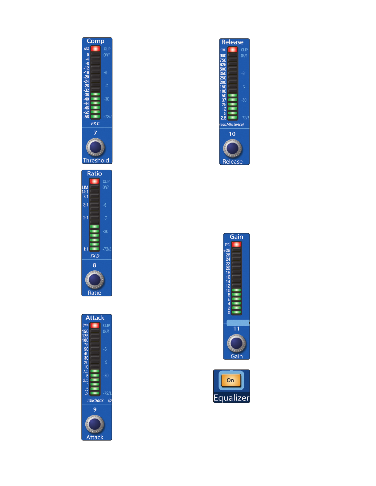
Compressor Threshold. Sets
and Displays the Threshold of the
Compressor for the Selected
Channel or Output Bus.
This encoder sets, and the
meter displays, the compressor
threshold for the selected
channel or output bus. When
the signal’s amplitude (level)
exceeds the threshold setting,
the compressor engages. Turning
the knob counterclockwise
lowers the threshold so that
compression begins at a lower
amplitude. The threshold can
be set from -56 to 0 dB.
Ratio. Sets and Displays the
Compression Ratio for the
Selected Input Channel or
Output Bus.
This encoder sets, and the
meter displays, the compression
ratio (or slope) for the selected
channel or output bus. The ratio
sets the compression slope,
which is a function of the output
level versus the input level. For
example, if you have the ratio
set to 2:1, any signal levels above
the threshold setting will be
compressed at a ratio of 2:1. This
means that for every 2 dB of level
increase above the threshold,
the compressor’s output will
only increase 1 dB. The ratio
can be set from 1:1 to 14:1.
Compressor Attack. Sets and
Displays the Compressor Attack
Setting for the Selected Input
Channel or Output Bus.
This encoder sets, and the meter
displays, the compressor’s attack
setting for the selected channel
or output bus. Attack sets the
speed at which the compressor
acts on the input signal. A slow
attack time (fully clockwise)
allows the beginning component
of a signal (commonly referred
to as the initial transient) to
pass through, uncompressed,
whereas a fast attack time (fully
counterclockwise) triggers
compression immediately when
a signal exceeds the threshold.
You can set the attack from
0.2 to 150 milliseconds.
Compressor Release. Sets and
Displays the Compressor Release
Setting for the Selected Input
Channel or Output Bus.
This encoder sets, and the
meter displays, the release
setting of the compressor for
the selected channel or output
bus. Release sets the length of
time the compressor takes to
return the gain reduction back
to zero (no gain reduction) after
crossing below the compression
threshold. Release can be set
from 2.5 to 900 milliseconds.
Power User Tip: Very short release
times can produce a choppy or
“jittery” sound, especially when
compressing instruments that
have a lot of low-frequency
components, such as bass guitar.
Very long release times can result in
an overcompressed, or “squashed,”
sound. All ranges of release can be
useful, however, and you should
experiment to become familiar
with different sonic possibilities.
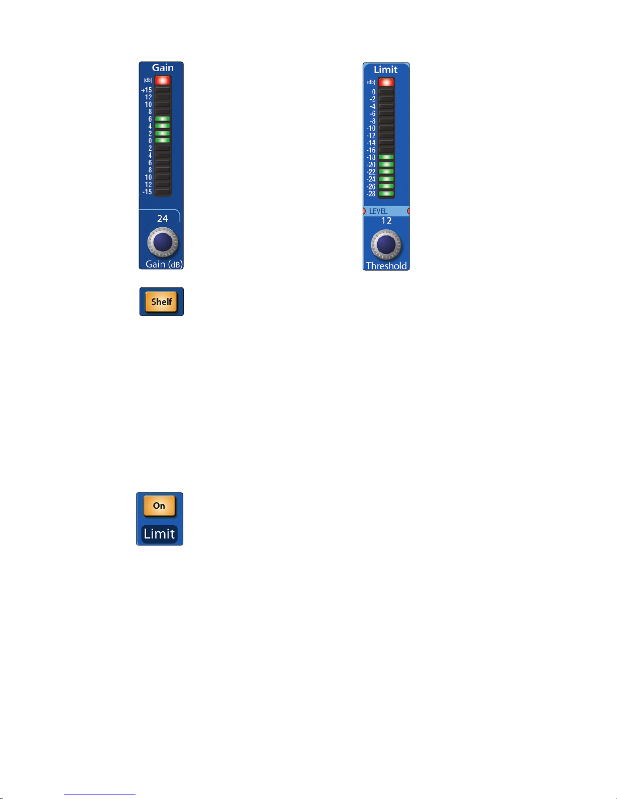
Compressor Makeup Gain. Sets
and Displays the Amount of
Makeup Gain for the Compressor
on the Selected Input Channel or
Output Bus.
This encoder sets, and the meter
displays, the makeup-gain
setting of the compressor for the
selected channel or output bus.
When compressing a signal, gain
reduction usually results in an
overall attenuation of level. The
gain control allows you to restore
this loss in level and readjust the
volume to the precompression
level (if desired). You can adjust
Makeup Gain from 0 dB (no gain
adjustment) to +28 dB.
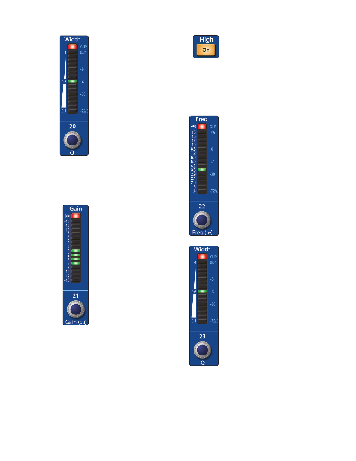
Equalizer On/Off Button.
Globally switches all EQ Bands On
or Off for the Selected Input
Channel or Output Bus.
This button engages or
disengages the equalizer for the
selected channel or output bus.
It will illuminate to indicate that
the equalizer has been enabled.
The equalizer is available for
all 32/24/16 input channels
and every output bus.
23
4 Controls
4.1 The Fat Channel
StudioLive™ 32.4.2AI
Owner’s Manual
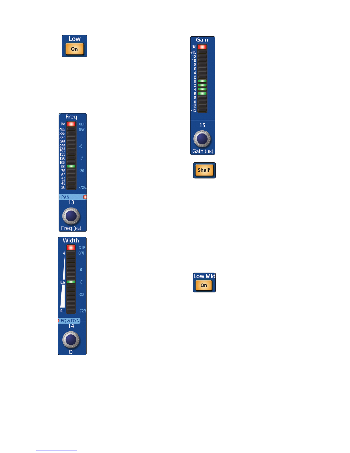
Low EQ On/Off Button. Turns
the Low Band EQ On/Off for the
Selected Input or Output Bus.
This button activates the
equalizer’s Low band for
the selected channel or bus.
The button will illuminate to
indicate control is active.
The Low EQ band is available
for all 32/24/16 input channels
and every output bus.
Low EQ Frequency Control. Sets
and Displays the Center
Frequency of the Low EQ Band.
This encoder sets, and the meter
displays, the center frequency
of the equalizer’s Low band.
The center frequency is the
middle of the passband (the
mean) between the lower and
upper cutoff frequencies that
define the limits of the band.
You can adjust the center
frequency from 36 to 465 Hz.
Low EQ Q Control (32.4.2AI and
24.4.2AI only). Sets and Displays
the Q of the Low Frequency
Band.
This encoder sets, and the meter
displays, the Q for the Low band.
The Q is the ratio of the center
frequency to the bandwidth.
When the center frequency
is constant, the bandwidth is
inversely proportional to the Q,
so as you raise the Q, you narrow
the bandwidth.
Low EQ Gain Control. Sets and
Displays the Gain Attenuation or
Boost of the Center Frequency.
This encoder sets, and the meter
displays, the gain cut or boost
at the center frequency for the
Low band. The level of the center
frequency can be set between
-15 and +15 dB.
Low Shelf EQ Button. Turns on
the Low Shelving EQ for the
Selected Input or Output Bus.
When the Shelf button is not
engaged, the Low band is
parametric. Enabling the Shelf
button turns the Low band into
a low-shelving EQ that alters,
by a fixed amount, a band of
low frequencies at and below a
user-selected shelving frequency.
Power User Tip: A low shelving
EQ is like a bass-control knob
on a stereo. In this mode, the
Center Frequency control selects
the shelving frequency.
Low-Mid EQ On/Off Button.
Turns the Low-Mid EQ On/Off for
the Selected Input or Output Bus.
This button activates the
equalizer’s Low-Mid band for
the selected input or output.
The button will illuminate to
indicate control is active.
The Low-Mid EQ is available
for all 32/24/16 input channels
and every output bus.
24
4 Controls
4.1 The Fat Channel
StudioLive™ 32.4.2AI
Owner’s Manual
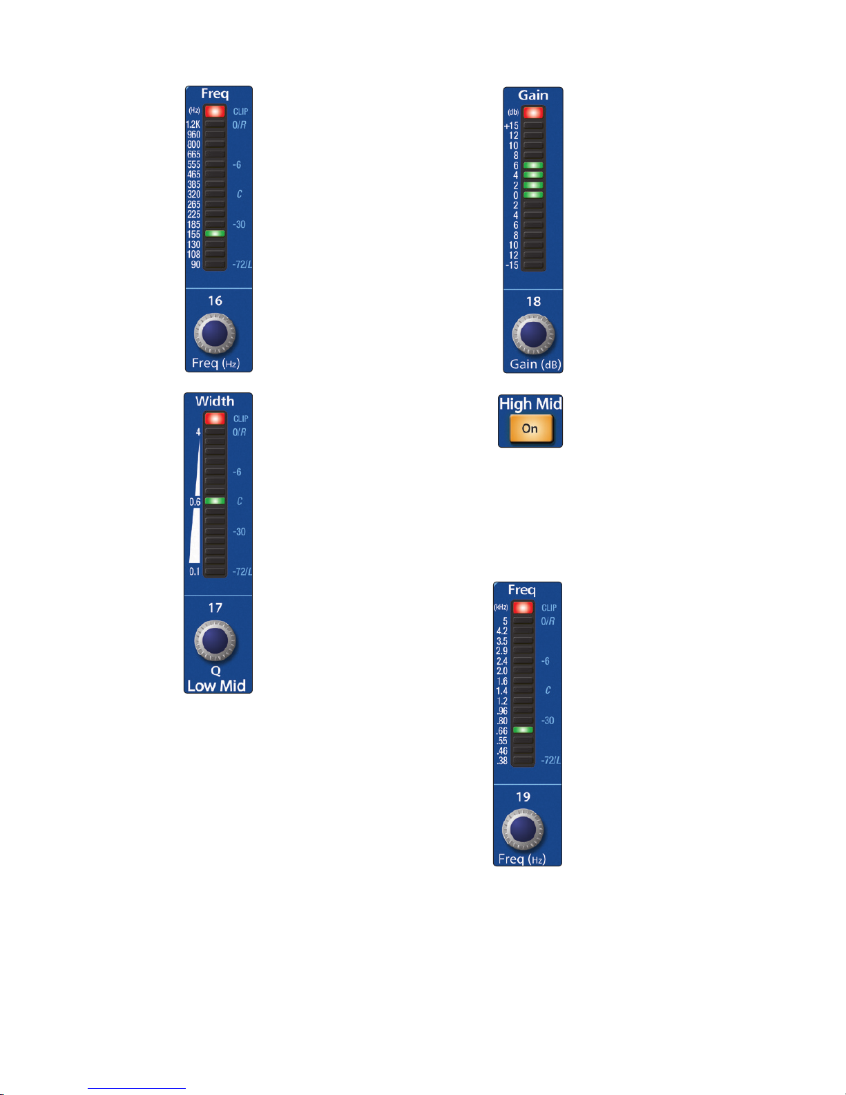
Low-Mid EQ Frequency
Control. Sets and Displays the
Center Frequency of the Low-Mid
EQ.
This encoder sets, and the meter
displays, the center frequency
for the Low-Mid band. You can
adjust the center frequency from
90 Hz to 1.2 kHz.
Low-Mid EQ Q Control (32.4.2AI
and 24.4.2AI only). Sets and
Displays the Q of the Low Mid
Frequency Band.
This encoder sets, and the
meter displays, the Q for the
Low-Mid band. The Q is the
ratio of the center frequency
to the bandwidth. When the
center frequency is constant,
the bandwidth is inversely
proportional to the Q, so as
you raise the Q, you narrow the
bandwidth.
Note: While the StudioLive 16.4.2AI
doesn’t have a variable Q control
for any of its bands, it does offer
a Hi Q button for the Low-Mid
Frequency Band. This button will
narrow the Q of the Low-Mid
Band to 2.0 to provide more exact
control. By default, the Low-Mid Q
is set to 0.55.
Low-Mid EQ Gain Control. Sets
and Displays the Gain
Attenuation or Boost of the
Center Frequency for the
Low-Mid Band.
This encoder sets, and the meter
displays, the Gain cut or boost at
the center frequency of the LowMid band. The level of the center
frequency can be set between
-15 and +15 dB.
High-Mid EQ On/Off Button.
Turns the High-Mid EQ On/Off for
the Selected Input or Output Bus.
This button activates the HighMid band for the selected
input or output. The button
will illuminate to indicate
that the control is active.
The High-Mid EQ is available
for all 32/24/16 input channels
and every output bus.
High-Mid EQ Frequency
Control. Sets and Displays the
Center Frequency of the HighMid EQ.
This encoder sets, and the meter
displays, the center frequency
of the High Mid band. You can
adjust the center frequency from
380 Hz to 5 kHz.
25
4 Controls
4.1 The Fat Channel
StudioLive™ 32.4.2AI
Owner’s Manual
High-Mid EQ Q Control
(32.4.2AI and 24.4.2AI only).
Sets and Displays the Q of the
High Mid Frequency Band.
This encoder sets, and the
meter displays, the Q for the
High-Mid band. The Q is the
ratio of the center frequency
to the bandwidth. When the
center frequency is constant,
the bandwidth is inversely
proportional to the Q, so as
you raise the Q, you narrow the
bandwidth.
Please Note: While the StudioLive
16.4.2AI doesn’t have a variable Q
control for any of its bands, it does
offer a Hi Q button for the HighMid Frequency Band. This button
will narrow the Q of the High-Mid
Band to 2.0 to provide more exact
control. By default, the High-Mid Q
is set to 0.55.
High-Mid EQ Gain Control. Sets
and Displays the Gain
Attenuation or Boost at the
Center Frequency.
This encoder sets, and the meter
displays, the gain cut or boost at
the center frequency of the HighMid band. The level of the center
frequency can be set between
-15 and +15 dB.
High EQ On/Off Button. Turns
the High EQ On/Off for the
Selected Input or Output Bus.
This button activates the High
band for the selected channel or
bus. The button will illuminate
to indicate control is active.
The High EQ band is available for
all 32/24/16 input channels and
every output bus.
High EQ Frequency Control.
Sets and Displays the Center
Frequency of the High EQ.
This encoder sets, and the meter
displays, the center frequency
of the High band. You can adjust
the center frequency from 1.4 to
18 kHz.
High EQ Q Control (32.4.2AI
and 24.4.2AI only). Sets and
Displays the Q of the High
Frequency Band.
This encoder sets, and the meter
displays, the Q for the High band.
The Q is the ratio of the center
frequency to the bandwidth.
When the center frequency
is constant, the bandwidth is
inversely proportional to the Q,
so as you raise the Q, you narrow
the bandwidth.
26
4 Controls
4.1 The Fat Channel
StudioLive™ 32.4.2AI
Owner’s Manual
High EQ Gain Control. Sets and
Displays the Gain Attenuation or
Boost at the Center Frequency of
the High Frequency Band.
This encoder sets, and the meter
displays, the gain cut or boost at
the center frequency of the High
EQ band. The level of the center
frequency can be set between
-15 and +15 dB.
High Shelf EQ Button. Turns on
the High Shelving EQ for the
Selected Input or Output Bus.
When the Shelf button is not
engaged, the High band is a
parametric EQ. Enabling the Shelf
button turns the High band into
a high shelving EQ that alters,
by a fixed amount, a band of
high frequencies at and above a
user-selected shelving frequency.
Power User Tip: A high shelving
EQ is like a treble-control knob on
a stereo. In this mode, the Center
Frequency control selects the
shelving frequency.
Limiter On/Off. Turns on the
Limiter for the Selected Input
Channel or Output Bus.
When the limiter is engaged
the button will illuminate.
The ratio is ∞:1.
The Limiter is available for
all 32/24/16 input channels
and every output bus.
Limiter Threshold (32.4.2AI and
24.4.2AI only). Sets and Displays
the Threshold of the Limiter for
the Selected Channel or Output
Bus.
This encoder sets, and the meter
displays, the threshold of the
limiter for the selected channel
or output bus. When the signal’s
amplitude (level) exceeds the
threshold setting, the limiter
is engaged. Turning the knob
counterclockwise lowers the
threshold, so limiting begins at a
lower amplitude. The threshold
can be set from -28 to 0 dB.
 Loading...