

Presonus StudioLive 32S, StudioLive 32SC, StudioLive 64S Owner’s Manual
StudioLive™ Series III
Digital Mix Console / Recorder with Motorized Faders
Owner’s Manual
®
www.presonus.com
English

Table of Contents
1 Overview — 1
1.1 Introduction — 1
1.2 About this Manual — 1
1.3 Companion PreSonus Products — 2
1.4 What’s in the Box — 3
1.5 Additional Resources — 4
3.4 Typical Band Setup Diagrams — 20
3.5 Typical Church Setup Diagrams — 21
4 Basic Mix Functions Overview — 22
4.1 Channel Strip Basics — 22
4.2 Fader Layers and Banks — 23
4.2.1 User Fader Layer — 24
4.3 Filter DCA Groups — 25
4.3.1 Creating Filter DCAs — 25
2 Getting Started — 5
2.1 Level Setting Procedure — 5
2.2 Useful Concepts — 9
2.2.1 Select Buttons and the Fat Channel — 9
2.2.2 Fat Channel Plugins — 10
2.2.3 FlexMixes — 10
2.2.4 Fader Layers — 10
2.2.5 DCA Groups — 11
2.2.6 Recording and Playback — 11
2.2.7 Digital Patching — 11
2.2.8 Projects, Scenes, and Presets — 11
2.2.9 User Profiles — 12
3 Hookup — 13
3.1 Rear Panel Configurations — 13
3.1.1 StudioLive 64S — 13
3.1.2 StudioLive 32S — 13
3.1.3 StudioLive 32SX — 14
4.3.2 Editing or Deleting
a Filter DCA Group — 26
4.3.3 Managing DCA Group Masters — 26
4.3.4 DCA Group Options — 27
4.4 Main Meters — 27
4.5 Talkback System — 27
4.5.1 Talkback Edit Screen — 28
5 Buses and Routing — 29
5.1 FlexMixes — 29
5.2 Aux Mixes — 30
5.2.1 Pre/Post Channel Sends — 31
5.2.2 Creating Aux Mixes — 31
5.2.3 Working with
External Effects Processors — 32
5.3 Subgroups — 33
5.3.1 Creating a Subgroup — 34
5.3.2 Fixed Subgroups
(32-channel models only) — 34
3.1.4 StudioLive 32SC — 14
3.1.5 StudioLive 32 (Blue Model) — 15
3.1.6 StudioLive 24 (Blue Model) — 15
3.1.7 StudioLive 16 (Blue Model) — 15
3.2 Rear Panel Connections — 16
3.2.1 Analog Inputs — 16
3.2.2 Analog Outputs — 17
3.2.3 Digital and Networking — 18
3.2.4 Power — 19
3.3 Top Panel Connections — 19
5.3.3 Creating Instrument Subgroups — 35
5.4 Matrix Mixes — 37
5.4.1 Creating a Matrix Mix — 37
5.4.2 Creating a Front Fill Mix — 38
5.5 FX Buses — 38
5.5.1 Creating Internal Bus FX Mixes — 39
5.6 Main Mono/Center Bus
(StudioLive 64S only) — 39
5.6.1 Mono Bus Mode — 40
5.6.2 LCR Mode — 41

6 The Fat Channel — 43
7 Tape Controls — 73
6.1 Overview — 43
6.1.1 A/B Comparison for EQ
and Dynamics Settings — 44
6.1.2 Copy/Paste & Preset Load/Save — 44
6.2 Fat Channel Navigation — 46
6.3 Input Mode — 48
6.4 Gate Mode (Dynamic Fat Channel) — 50
6.4.1 Dynamic Fat Channels Controls — 50
6.5 Compressor Mode (Dynamic Fat Channel) — 51
6.5.1 Standard Compressor — 51
6.5.2 Tube Leveling Amplifier — 52
6.5.3 Class-A FET Compressor — 53
6.6 EQ Mode (Dynamic Fat Channel) — 54
6.6.1 Standard EQ — 54
6.6.2 Passive Program EQ — 55
6.6.3 Vintage 1970s EQ — 55
6.7 Aux Sends Mode (Dynamic Fat Channel) — 56
7.1 Pairing a Bluetooth Device — 73
8 SD Recording — 74
8.1 Creating a New Session for Recording — 74
8.2 Loading a Session for Playback — 75
8.3 Capture Screen — 75
8.3.1 Recording Status Messages — 76
8.3.2 Transport Controls — 77
8.4 Virtual Sound Check — 78
9 Master Control — 79
9.1 StudioLive Series III FX Rack — 79
9.1.1 The Effects Editor — 80
9.1.2 Effects Types — 80
9.1.3 Effects Presets — 84
9.4 UCNET — 85
9.4.1 Mixer Nickname — 85
9.4.2 Permissions — 85
6.8 Fat Channel Screens — 57
6.8.1 Channel Overview — 57
6.8.2 Channel Settings Screen — 58
6.8.3 Gate Overview Screen — 59
6.8.4 Compressor Overview Screens — 60
6.8.5 EQ Overview Screens — 63
6.8.6 Aux Sends Overview Screen — 68
6.9 User Mode — 68
6.10 Input Controls — 68
6.10.1 Input Source — 68
6.10.2 Input Meters — 69
6.10.3 Input Source Routing — 69
6.10.4 Polarity and Phantom Power — 71
6.10.5 Stereo Link — 71
6.11 Output Assignment Buttons — 72
6.11.1 Main/Mono Bus Assignment
(StudioLive 64S only) — 72
6.11.2 Main/Subgroup Assignment (All 32-Channel
StudioLive Models) — 72
9.4.3 Software Control — 86
9.4.4 Control Network IP Address
Settings — 87
9.4.5 Transport Controls — 87
9.5 DAW Button — 88
9.6 Scenes and Projects — 88
9.6.1 Creating and Recalling Projects — 88
9.6.2 Creating and Recalling Scenes — 89
9.6.3 Filters — 91
9.6.4 List Editor — 93
9.6.5 Scene Safe — 94
9.6.6 AutoStore — 94
9.6.6 Reset — 95
9.6.7 Nulling Parameters — 96
10 Monitoring Controls — 97
10.1 Solo Controls — 97
10.1.1 Solo Modes — 98
10.1.2 Using the Solo Bus for Monitoring — 99

10.1.3 Using Solo in Place to
Set Up a Mix — 100
13.2.2 Electric Guitar — 122
13.2.3 Acoustic Guitar — 123
11 Graphic EQ — 101
11.1 Assigning GEQs — 102
11.2 Using the GEQ — 102
11.3 GEQ Presets — 103
11.4 Using the RTA to Ring Out Monitors — 103
12 Home — 105
12.1 System Screen — 106
12.1.1 Permissions — 107
12.1.2 User Buttons Assigns — 107
12.1.3 Fat Channel Load/Paste — 108
12.1.4 Firmware Update — 109
12.1.5 Link Aux Mutes — 109
12.2 User Profiles — 109
12.2.1 Default Administrator — 110
12.2.2 Creating a New Profile — 111
12.2.2 Edit User Permissions — 113
12.3 Audio Routing and the Digital Patching
Screen — 114
12.3.1 Digital Patching: Input Source — 115
12.3.2 Digital Patching: Analog Sends — 115
12.3.3 Digital Patching: AVB Sends — 116
12.3.4 Digital Patching: USB Sends — 117
12.3.5 Digital Patching: SD Card — 118
12.3.6 Digital Patching: AES — 118
12.4 Utilities — 119
13.2.4 Bass Guitar (Direct and Speaker) — 123
13.2.5 Drum Overheads (XY example) — 124
13.2.6 Snare Drum (top and bottom) — 124
13.3 Compression Setting Suggestions — 125
13.3.1 Vocals — 125
13.3.2 Percussion — 125
13.3.3 Fretted Instruments — 125
13.3.4 Keyboards — 126
13.3.5 Stereo Mix — 126
13.3.6 Effects — 126
13.4 EQ Frequency Guides — 127
13.4.1 What Frequencies to Cut and
Boost — 127
13.4.2 Instrument Ranges — 128
13.5 EQ Setting Suggestions — 128
13.5.1 Vocals — 128
13.5.2 Percussion — 129
13.5.3 Fretted Instruments — 130
13.5.4 Keyboards — 130
13.6 Using Input Delay — 131
13.6.1 Aligning the Backline with Vocal
Mic — 131
13.6.2 Aligning Direct and Mic’d Signals — 132
13.7 Using Output Delay — 133
13.7.1 Front-of-House — 133
13.7.2 Delay Systems — 134
13.7.3 Aligning Subs to Mains — 135
12.5 Soft Power — 119
13 Resources — 120
13.1 Networking Overview — 120
13.1.1 Wired Ethernet Control Setup — 120
13.2 Stereo Microphone Placement — 122
13.2.1 Grand Piano — 122
13.8 Sidechaining — 136
13.8.1 Sidechaining the Gate — 136
13.8.2 Sidechaining the Compressor — 137
13.9 Effect Types — 137
13.9.1 Reverb and its Parameters — 137
13.9.2 Delay and its Parameters — 138
13.10 Using the RTA While Mixing — 139

14 Technical Information — 140
14.1 Specifications — 140
14.2 Default Routing — 142
14.2.1 Input Source — 142
14.2.2 Analog Sends — 144
14.2.3 AVB Sends — 145
14.2.4 USB Sends — 146
14.2.5 SD Card — 148
14.3 Block Diagrams — 149
14.4 Troubleshooting Information — 149
15 Warranty — 150
15.1 Warranty Information — 150
1 Overview
1.1 Introduction
1 Overview
1.1 Introduction
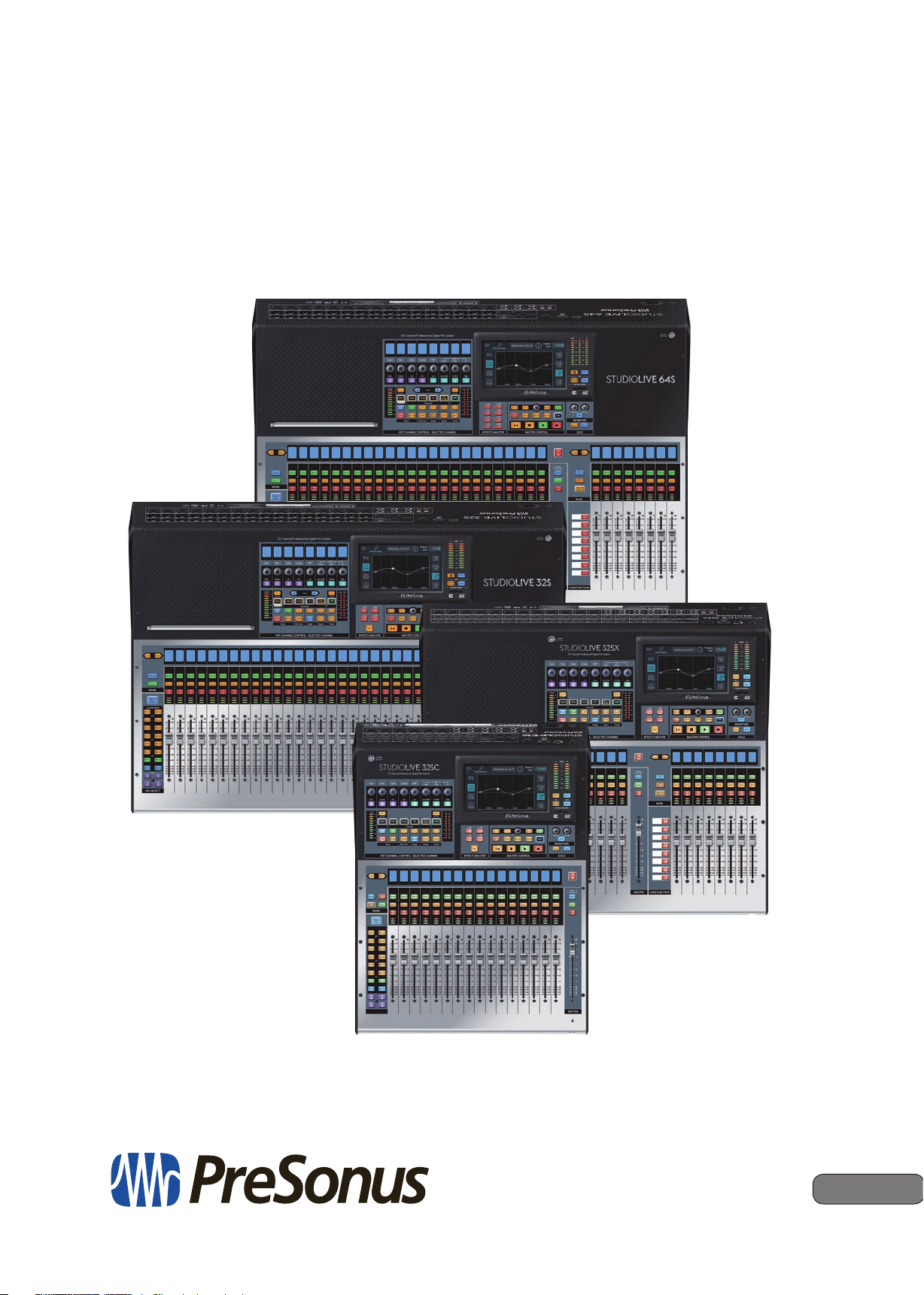
StudioLive™ Series III
Owner’s Manual
Thank you for purchasing your PreSonus® StudioLive™ Series III Digital Mixer.
PreSonus Audio Electronics has built your StudioLive mixer with high-grade
components to ensure optimum performance for many years to come. StudioLive
Series III breaks new boundaries for music performance and production.
We encourage you to contact us with questions or comments regarding this product.
PreSonus Audio Electronics is committed to constant product improvement, and
we value your suggestions highly. We believe the best way to achieve our goal
of constant product improvement is by listening to the real experts: our valued
customers. We appreciate the support you have shown us through the purchase of
this product.
1.2 About this Manual
We suggest that you spend some time with this manual before starting to work with
your StudioLive Series III mixer, to familiarize yourself with its features, workflows, and
connection procedures. This will help your setup process go as smoothly as possible.
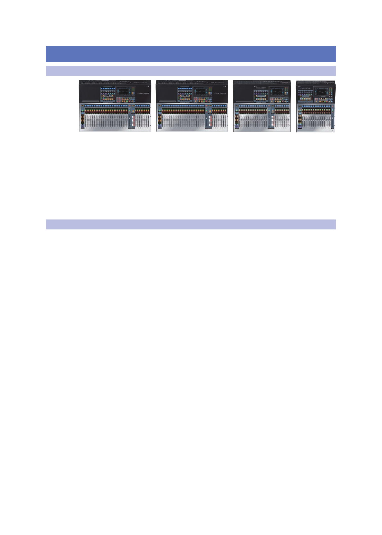
This manual applies to all StudioLive Series III mixers. While every StudioLive Series
III mixer provides nearly identical mixing capabilities, some features and workflows
vary between models. Where these differences occur, they will be called out. All
illustrations for shared features and functions will show a StudioLive 64S.
This manual covers the following hardware products:
StudioLive Series III S Models
• StudioLive 64S
• StudioLive 32S
• StudioLive 32SX
• StudioLive 32SC
StudioLive Series III Blue Models (requires v. 2.0 firmware or later)
• StudioLive 32
• StudioLive 24
• StudioLive 16
Throughout this manual, you will find Power User Tips, providing mixing tricks and
explanations of various useful audio terms. Near the end of this manual, you’ll find
a selection of audio tutorials, covering everything from microphone placement to
recommended equalizer and compression settings. We hope these tutorials help you
to get the most from your StudioLive Series III mixer.
All models, except the StudioLive 64S, are 32-channel mixers and will be referred to
as such when differences occur between the StudioLive 64S and the other mixers in
the StudioLive Series III family.
Thank you, once again, for purchasing our product. We are confident that you will
enjoy your new StudioLive.
1
1 Overview
1.3 Companion PreSonus Products
1.3 Companion PreSonus Products
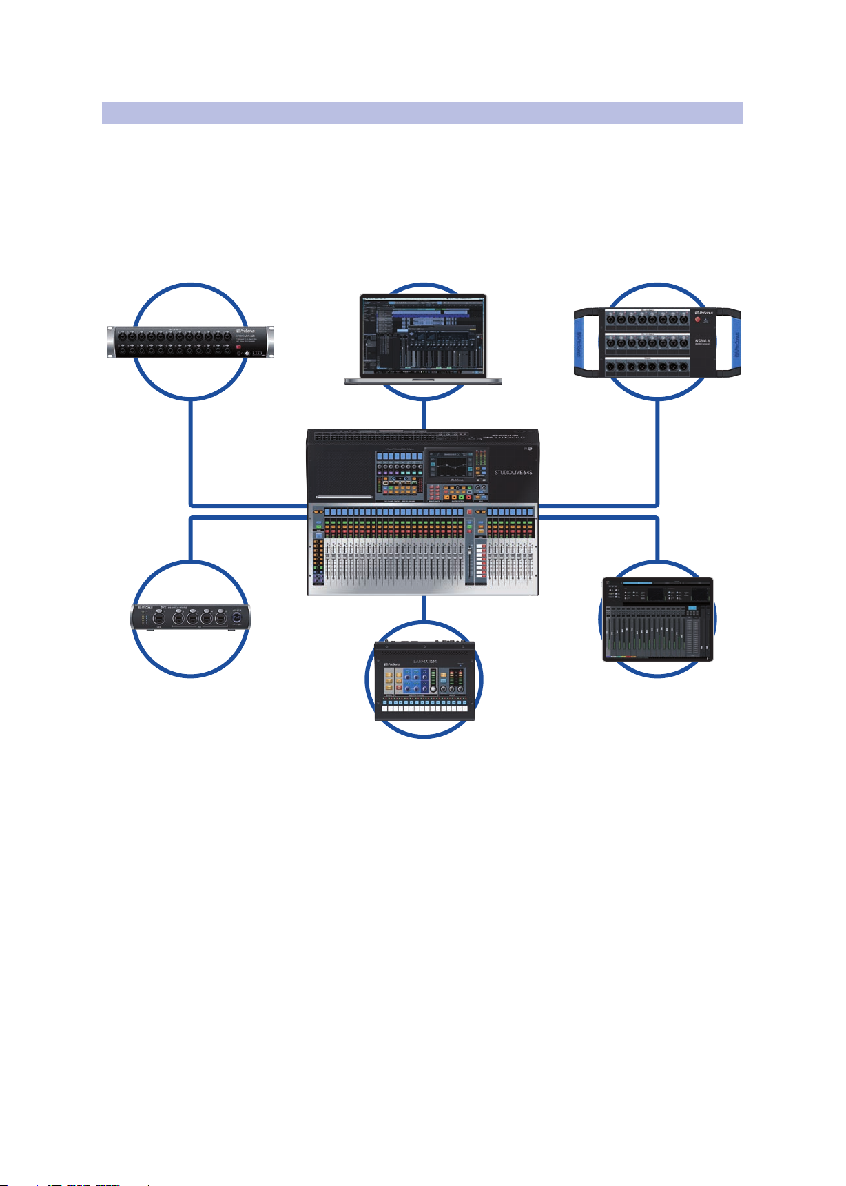
Welcome to the PreSonus Ecosystem! As a solutions company, we believe the best
way to take care of our customers (that’s you) is to ensure that you have the best
possible experience from the beginning of your signal chain to the end. In order to
achieve this goal, we’ve prioritized seamless integration throughout every design
phase of these products from day one. The result is systems that communicate with
each other as intended— straight out of the box—without excessive
configuration hassle.
StudioLive™ Series III
Owner’s Manual
For more information on how our PreSonus AVB networking devices play so well with
one another, please review the PreSonus AVB Networking Guide.
For more information on individual products, please visit www.presonus.com.
2
1 Overview
1.4 What’s in the Box
1.4 What’s in the Box
StudioLive™ Series III
Owner’s Manual
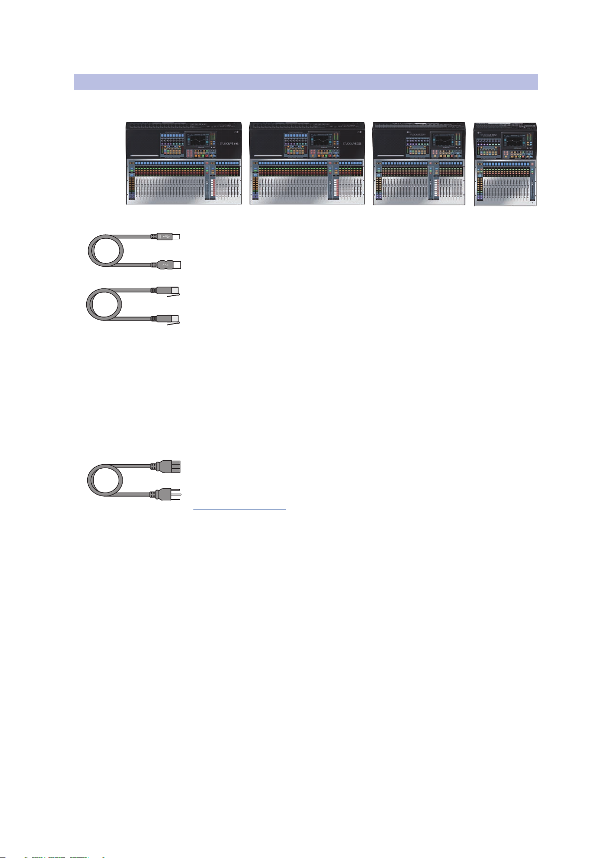
In addition to a Visual Quick Start Guide, your StudioLive package contains the
following:
• A PreSonus StudioLive Series III digital recording and performance mixer
• 1 meter USB cable
• 1 meter CAT6 Ethernet cable
• StudioLive Series III Quick Start Guide
• IEC power cord
Power User Tip: All companion software and drivers for your PreSonus StudioLive Series
III mixer are available for download from your My PreSonus user account. Please visit
http://my.presonus.com and register your StudioLive Series III mixer to receive downloads
and licenses.
3

1 Overview
1.5 Additional Resources
1.5 Additional Resources
Software Guides:
• Capture 3 Reference Manual. Included with StudioLive mixers is Capture, a
• Networking for StudioLive Remote Control. This guide will assist you in creating
• QMix-UC Reference Manual. This guide describes the features and functions
• Studio One Integration Reference Manual. Studio One Artist is included with
• UC Surface Reference Manual. This guide describes the features and functions
• Using Your StudioLive as an Audio Interface with Universal Control Reference
StudioLive™ Series III
Owner’s Manual
digital-audio multitrack-recording application designed to make recording quick
and easy.
a LAN network to remote control your StudioLive from a computer, tablet, or
mobile device.
of QMix-UC with every StudioLive mixer model. QMix-UC lets up to 16 users
remotely control the Aux Mixes on your StudioLive using their smartphone.
every StudioLive mixer. In addition to being a powerful DAW, Studio One provides
unique routing and integration features. This manual will help you get the most
from your StudioLive mixer when used with Studio One or Studio One Artist.
of UC Surface with every StudioLive mixer model. UC Surface can be used to
remotely control ever function on your StudioLive mixer or specific functions,
depending on the set permissions, or to turn your tablet into additional screens
for your mixer.
Guide. This guide describes the features and functions Universal Control as well
as how to use your StudioLive mixer as an audio interface with your favorite DAW
application.
Additional Resources:
• StudioLive Series III AVB Networking Guide. This manual covers advanced AVB
audio networking configuration for the StudioLive Series III mixers.
• StudioLive Series III Fat Channel Plug-ins Addendum. Additional Fat Channel
plug-in models can be purchased from PreSonus.com. This guide covers the
installation and authorization process as well as the features of each plug-in
model.
• StudioLive Series III HUI for ProTools DAW Control Addendum. StudioLive Series
III console mixers can control Avid ProTools® using HUI emulation.
• StudioLive Series III MCU for Logic DAW Control Addendum. StudioLive Series
III console mixers can control Apple Logic® using Mackie Control Universal
emulation.
• StudioLive Series III Stage Box Mode Addendum. The StudioLive Series III
rackmount mixers (StudioLive 32R, StudioLive 24R, StudioLive 16R) can be used as
advanced stage boxes for any StudioLive Series III console mixer.
• StudioLive Series III Studio One DAW Control Addendum. StudioLive Series III
console mixers can be used to control Studio One and Studio One Artist.
4
2 Getting Started
2.1 Level Setting Procedure
2 Getting Started
Before you begin, here are a few rules to get you started:
• Always turn down the Main fader and both the Monitor and Phones knobs in the
Monitor section before making connections.
• Before plugging or unplugging a microphone while other channels are active,
mute the channel to which you are connecting.
• Your faders should be set on or near the “U” mark whenever possible. The “U”
indicates unity gain, meaning the signal is neither boosted nor attenuated.
• Do not allow your inputs to clip. Watch the level meters; when signal nears
Clipping, the top LED illuminates, indicating that the analog-to-digital converters
are in danger of being overdriven. Overdriving the converters will cause digital
distortion, which has a negative effect on sound quality.
Your P.A. and studio equipment should be powered on in the following order:
• Sound sources (keyboards, direct boxes, microphones, etc.) connected to the
StudioLive inputs
• StudioLive Series III mixer
• Computer (if applicable)
• Power amplifiers or powered loudspeakers
When it is time to power down, your system should be turned off in the reverse order.
Now that you know what not to do, let’s get started!
StudioLive™ Series III
Owner’s Manual
2.1 Level Setting Procedure
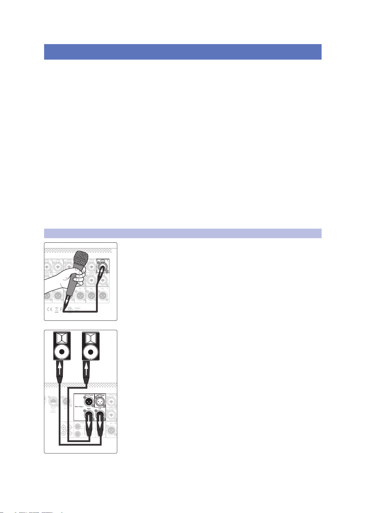
1. Plug a microphone into the Channel 1 input on your StudioLive Series III
with a standard XLR cable.
2. Connect the main outputs of your StudioLive to your powered monitors (or
power amp if using passive speakers).
5
2 Getting Started
Main
Mix
Mute Mute Mute Mute Mute Mute Mute
12 28
14 30
16 32
B F
D H
17 18
19 20
21 22
2
4
6
23 247 8
25 269 10
Inputs
User
Main
Mix
NextPrev
Solo
Mute
Select
Solo
Mute
Select
Solo
Mute
Select
Solo
Mute
Select
1 17 18
19 20
21 22
3
5
2
4
6
23 247 8
6
Ch. 67Ch. 78Ch. 89Ch. 910Ch. 1011Ch. 1112Ch. 1213Ch. 10
2.1 Level Setting Procedure
StudioLive™ Series III
Owner’s Manual
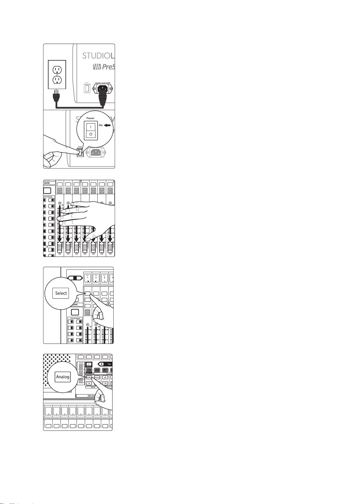
3. Plug your StudioLive into a power outlet and turn it on.
4. Move all of the faders on your StudioLive down to the lowest setting.
5. Press the Select button on Channel 1 to bring its settings into focus in the
Fat Channel.
6. Press the Analog button in the Fat Channel to patch in the analog input.
6
2 Getting Started
6
Ch. 67Ch. 78Ch. 89Ch. 910Ch. 1011Ch. 1112Ch. 1213Ch. 10
GATE
Thresh
-84.00 dB
Gate
COMP
Thresh
0.00 dB
Comp
Select Select Select Select Select Select Select Select Select
8
Ch. 89Ch. 910Ch. 1011Ch. 1112Ch. 1213Ch. 1313Ch. 13
GATE
Thresh
-84.00 dB
Gate
COMP
Thresh
0.00 dB
Comp
2.1 Level Setting Procedure
StudioLive™ Series III
Owner’s Manual
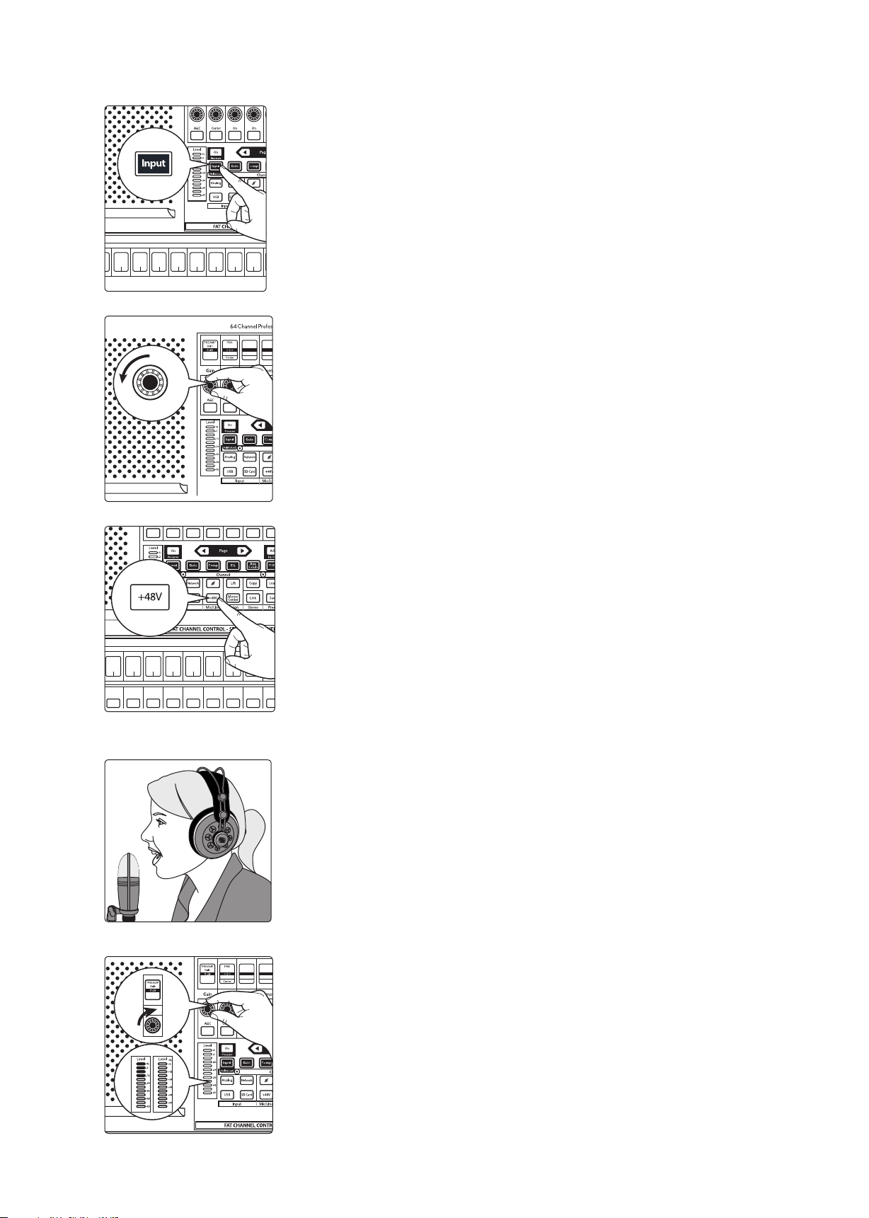
7. Press the Input button in the Fat Channel.
8. Turn the first knob in the Fat Channel section (Preamp Gain) counterclockwise to its lowest setting.
9. If your microphone requires phantom power, press the +48v button in the
Fat Channel.
10. Turn on your powered monitors or power amp.
11. Speak or sing into your microphone at the same volume as the
performance.
12. Turn the first knob in the Fat Channel section (Preamp Gain) clockwise while
watching the Level (input) meter in the Fat Channel. Adjust the Preamp
Gain knob until the meter shows an average level around the middle of its
range. Avoid lighting the red (clip) LED at the top of the meter.
7
2 Getting Started
11 27
13 29
15 31
12 28
14 30
16 32
A E
C G
B F
D H
1
17 18
19 20
21 2235
2
4
6
23 247 8
25 269 10
Select Select Select Select Select Select Select Select Select
9
Ch. 910Ch. 1011Ch. 1112Ch. 1213Ch. 1314Ch. 1415Ch. 1516Ch. 1317Ch. 13
1
2
3
4
5
6
7
8
GATE
Release
700 ms
GATE
Attack
5 ms
GATE
Range
-84.00 dB
GATE
Thresh
-84.00 dB
2.1 Level Setting Procedure
StudioLive™ Series III
Owner’s Manual
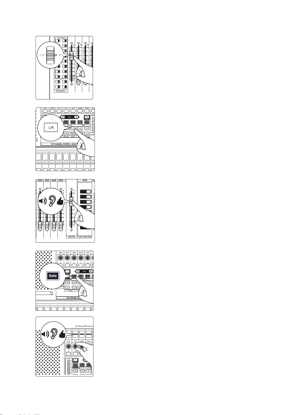
13. Raise the Channel 1 fader to its “U” setting (unity gain).
14. Press the “Main” button in the Fat Channel to assign Channel 1 to the Main
output bus.
15. Raise the Main fader while singing or speaking into the microphone until
you are satisfied with output level.
16. Select the Fat Channel processor (Gate, Compressor, or EQ) you would like
to edit first.
17. Use the controls in the Fat Channel or on the Touch Display to set the
parameters to taste.
StudioLive 32SX and 32SC Users will utilize the Touch Display to edit all Fat Channel
parameters. The controls in the Fat Channel are fixed to their designated function.
8
2 Getting Started
2.2 Useful Concepts
2.2 Useful Concepts
This section covers some basic workflow concepts to help you to more quickly get
acquainted with your StudioLive.
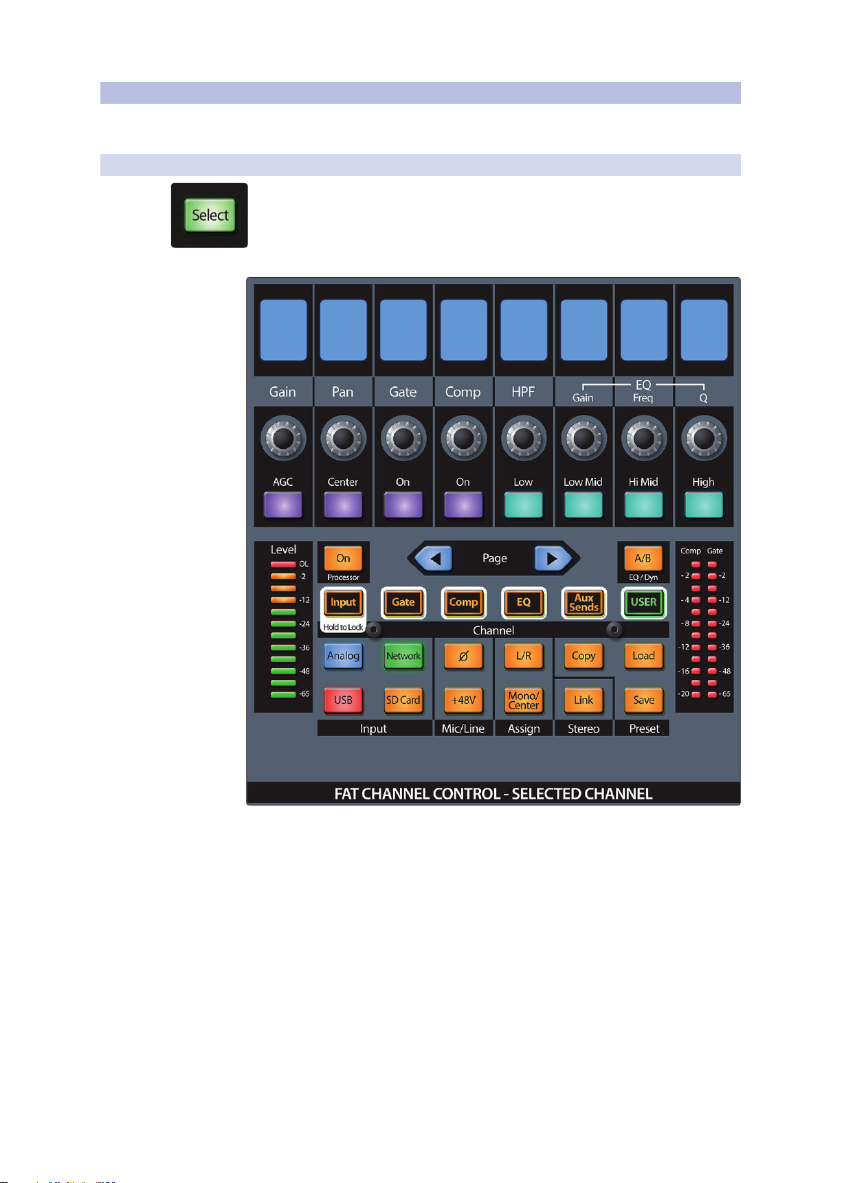
2.2.1 Select Buttons and the Fat Channel
All around the StudioLive, you will see Select buttons. There is a Select button on
each channel as well as the master fader. Each of these buttons serves exactly the
same purpose: to access the available Fat Channel parameters for its channel or bus.
These buttons will also change colors to alert you as to the type of mix you are
viewing (Aux, Subgroup, or Matrix)
StudioLive™ Series III
Owner’s Manual
The Fat Channel is the heart of the StudioLive. It gives you a wealth of powerful signal
processing, mixing, and configuration tools to help you make the most of your mixer.
Each channel and mix in your StudioLive can take advantage of the Fat Channel
functions at the touch of the corresponding Select button.
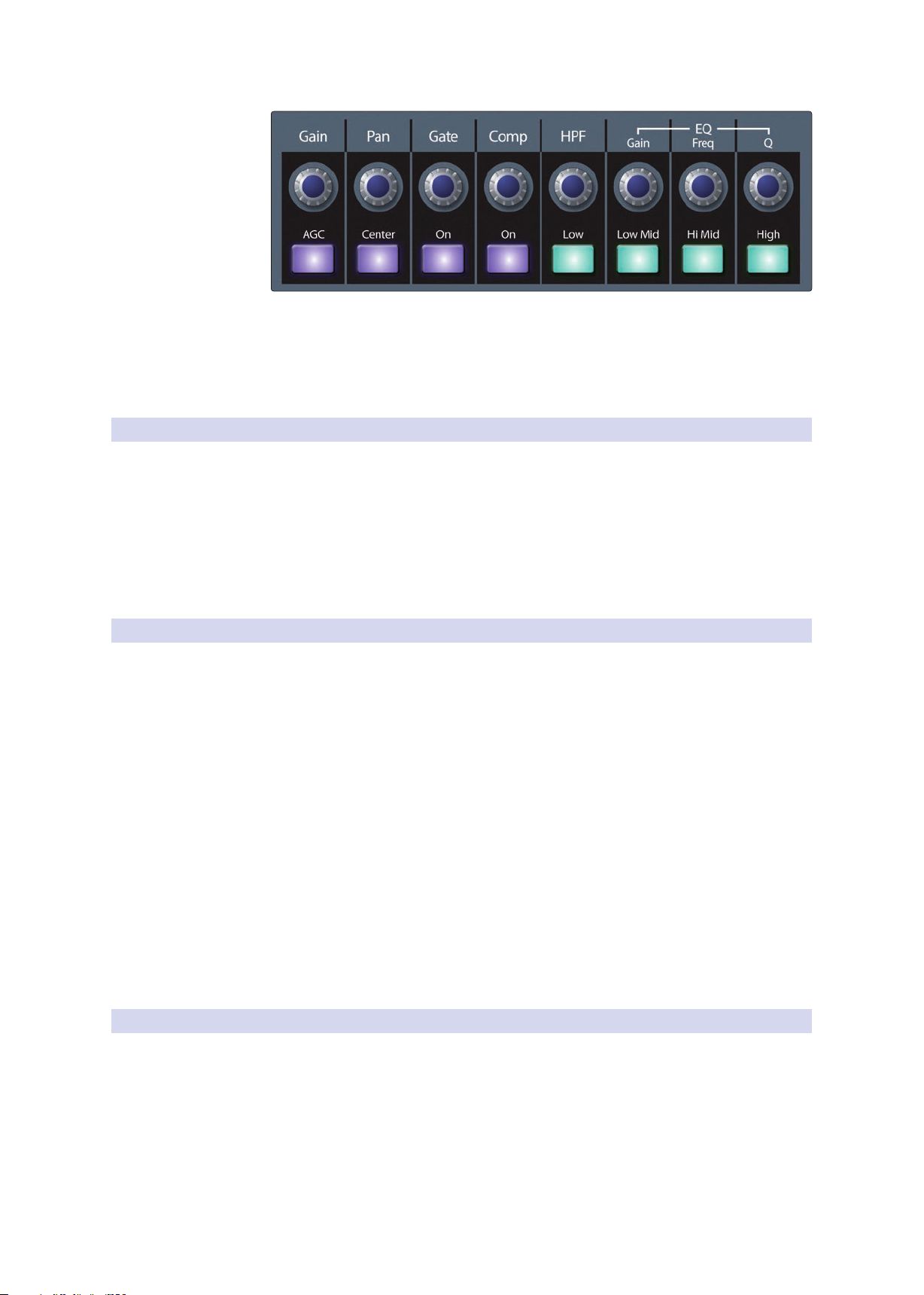
The 8 multipurpose knobs, buttons, and Scribble Strip displays in the Fat Channel
shift their functions to suit your needs as you move between tasks. The integrated
Touch Display works in tandem, providing useful information and fluid touch control.
9
2 Getting Started
2.2 Useful Concepts
The StudioLive 32SX and 32SC feature a Fixed mode Fat Channel that is locked to the
Input layer controls you need under your fingertips quickly. All other StudioLive users
can toggle between the Fixed and Dynamic modes by pressing and holding the
Input button in the Fat Channel.
For more information on using the Fat Channel system, see Section 6.
2.2.2 Fat Channel Plugins
The Compressor and EQ in the Fat Channel are equipped with multiple plug-in
models that can be loaded on each input and output to alter the sound and provide
your mix with more character. Additional Fat Channel plug-ins can be purchased
from the PreSonus Shop.
Every Fat Channel plug-in model can also be loaded in Studio One. Purchased
plug-ins come with both installers included.
For more information on loading a purchased Fat Channel models, see StudioLive
Series III Fat Channel Plug-ins Addendum.
StudioLive™ Series III
Owner’s Manual
2.2.3 FlexMixes
2.2.4 Fader Layers
In a traditional analog console, there are several different types of buses, each
feeding a dedicated output. Your StudioLive mixer features analog Mix outputs, each
driven by a FlexMix bus. Why do we call them FlexMixes? Because each FlexMix can
be configured as any one of three bus types:
• Pre- or Post-Fader Send Aux Bus. Aux buses provide auxiliary mixes that are
separate from the main and subgroup mixes.
• Subgroup. Subgroups are alternate buses that act much like the Main L+R bus on
your StudioLive.
• Pre- or Post-Fader Matrix Mix. Matrix mixes provide auxiliary mixes created from
any bus output as well as every input channel.
What’s more, FlexMixes can be stereo linked or used as mono, providing
maximum flexibility.
Power User Tip: Compact StudioLive Series III mixers, like the StudioLive 32SC, are
equipped with more FlexMix buses than physical analog FlexMix outputs. These
additional buses can be routed over the AVB network to NSB-series stageboxes, EarMix
personal monitor systems, and other mixers on the network.
For more information on using and configuring FlexMixes, see Section 5.1
To provide the most compact form factor, the StudioLive mixer utilizes fader layers.
Each layer allows you to view the channel strip controls for the input channels in each
mix. Additional fader layers allow you to view just the Aux Inputs, the DCA Group
outputs, or the Mix Master outputs.
More information about Fader Layers can be found in Section 4.2.
10

2 Getting Started
2.2 Useful Concepts
2.2.5 DCA Groups
Filter DCA Groups are a way to control the overall volume of a group of related
channels (such as all drum channels). While you can accomplish a similar result by
routing channels to a subgroup and controlling their volume with the subgroup
master, DCA Filter Groups require no such re-routing and offer some additional utility.
Filter DCA Groups provide two different fader functions: Default and Traditional.
• While in Default mode, the faders for the channels assigned to the Filter DCA
Group will move when the Filter DCA Group fader is adjusted. In this way, you
always have a clear visual cue of the actual fader level for every channel.
• While in Traditional mode, the faders for the channels assigned to the Filter DCA
Group will not move when the Filter DCA Group fader is adjusted.
For more information on using DCA Filter Groups, see Section 4.3.
2.2.6 Recording and Playback
The StudioLive Series III mixers are equipped with a 34-track SD recorder that is
completely integrated with your mixer, making multi-track recording and Virtual
Soundchecks quick and easy. Playback channels from the SD card can be switched
individually per channel.
In addition to the onboard SD recorder, a USB audio interface is also included. This
interface is continuously bidirectional, allowing you to use plugins as inserts as well
as recording and playback applications.
More information about SD recording and playback is available in Section 8.
More information on USB recording and playback is available in the Using Your
StudioLive as an Audio Interface with Universal Control Reference Guide.
StudioLive™ Series III
Owner’s Manual
2.2.7 Digital Patching
StudioLive Series III mixers allow you route any input to any channel and any mix to
any output. This enables you to create a customized configuration for your mixer. In
this way, you can patch any analog input or digital return (AVB, USB, or SD) to any
channel you like as well as route any FlexMix to any analog output, the AVB network,
or as sources for the USB audio interface and SD multitrack recorder.
The Digital Patching screen provides a detailed overview of what type of source is
feeding each channel, which input or return is patched to each channel, and where
each bus is routed.
For more information, please review Section 12.3.
2.2.8 Projects, Scenes, and Presets
Every parameter on your StudioLive mixer can be stored and recalled later. These
settings are saved as follows:
Projects
Global System settings and routing are stored within a Project. A Project saves the
mode for each FlexMix, Talkback assignments, and all the routing set in the Digital
Patching menu in addition to System settings like Sample Rate, Network Settings,
and Cue Source.
Because fundamental routing and bus structure is being changed when a Project is
recalled, the load time for Projects is slightly longer than loading a Scene or Preset.
It is recommended that Projects are not loaded during a performance or other live
application.
For more information on saving and loading Projects, see Section 9.6.1.
11

2 Getting Started
2.2 Useful Concepts
Scenes
Presets
2.2.9 User Profiles
StudioLive™ Series III
Owner’s Manual
Scenes that share the same Global System settings should be stored within the same
Project. Many Scenes can be stored within each Project. A Scene saves all the settings
you need to recall your mix like Channel Strip parameters, Fat Channel models and
settings, and Channel Identifiers like name, color, and type. Scenes created in one
Project cannot be recalled in any other Project.
For more information on saving and loading Scenes, see Section 9.6.2.
When you’ve dialed in a setting for a Fat Channel or FX processor that you’d like to
use on another channel later or in a future mix, you can save it as a Preset. Presets are
globally accessible from any Project or Scene. So, even if you’ve created the perfect
Reverb preset in one Project or Scene, you can recall it later from any other Project or
Scene.
For more information on saving and loading Fat Channel Presets, see Section 6.1.2.
User Profiles provide an easy way to grant access to some features and scenes to
some users, while locking out others. In this way, more advanced users can manage
critical functions like Digital Patching and bus configuration that cannot be changed
by guest users.
By default, an Admin profile is active when your StudioLive mixer is powered on. This
profile type has access to every feature and function on the mixer.
Restricted profiles are always locked out of the Settings, Audio Routing, and UCNET
screens and cannot lock or unlock scenes nor can they change a soft patch.
Restricted profiles can also be locked out from other optional functions as the Admin
user sees fit.
For more information on configuring and using User profiles, see Section 12.2.
12
3 Hookup
3.1 Rear Panel Configurations
3 Hookup
3.1 Rear Panel Configurations
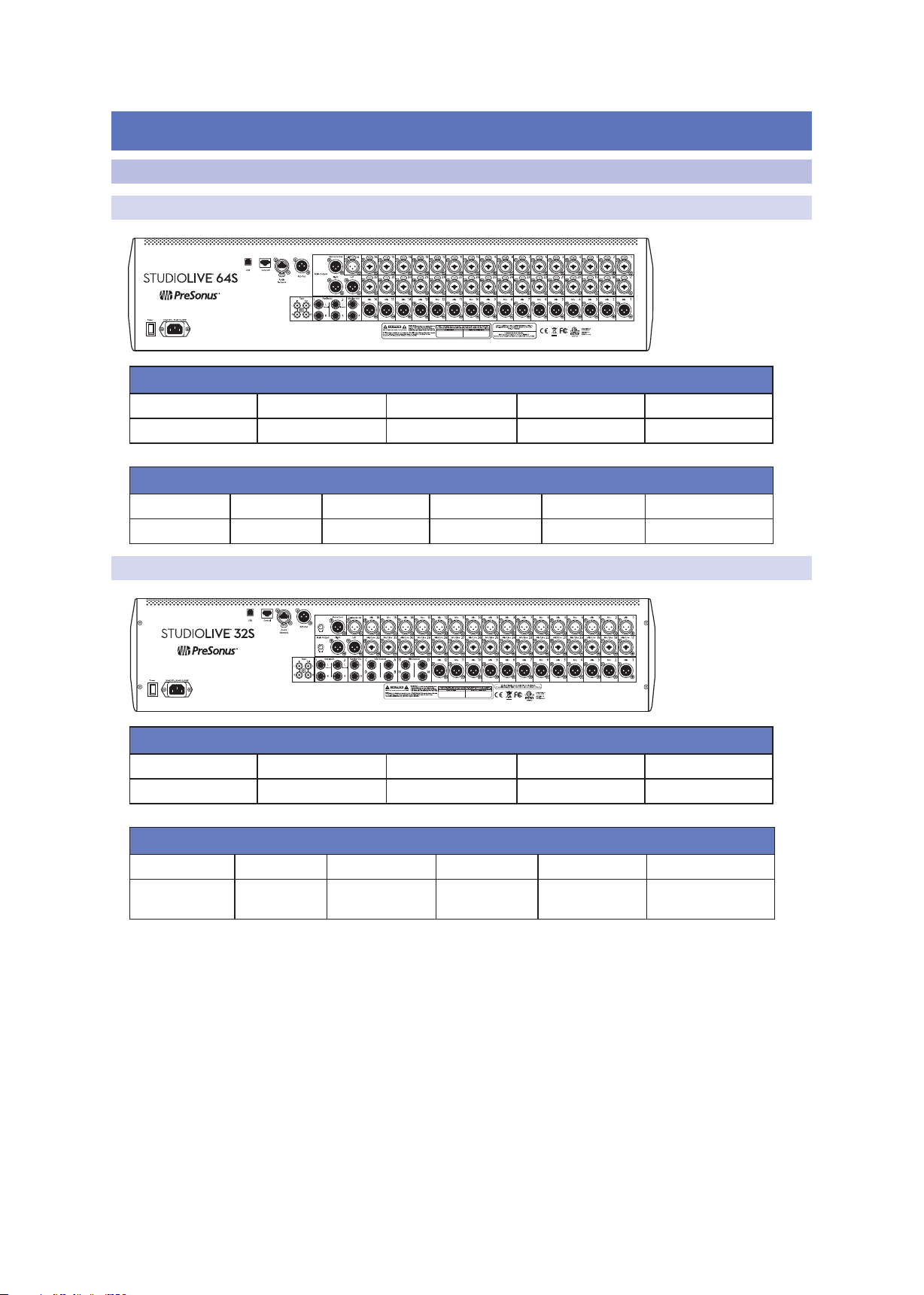
3.1.1 StudioLive 64S
Analog Inputs
Mic / Line Mic Only Aux Inputs Tape Inputs Talkback In
32 Combo n/a 4 1/4” TRS 2 RCA 1 XLR (F)
Analog Outputs
Flex Mix Subgroup Main Out Mono / Center Monitor Out Tape Out
16 XLR (M) n/a 2 XLR (M) 1 XLR (M) 2 1/4” TRS 2 RCA
StudioLive™ Series III
Owner’s Manual
3.1.2 StudioLive 32S
Analog Inputs
Mic / Line Mic Only Aux Inputs Tape Inputs Talkback In
16 Combo 16 XLR 4 1/4” TRS 2 RCA 1 XLR (F)
Analog Outputs
Flex Mix Subgroup Main Out Mono Sum Monitor Out Tape Out
12 XLR (M)
4 1/4” TRS
4 1/4” TRS 2 XLR (M) 1 XLR (M) 2 1/4” TRS 2 RCA
13
3 Hookup
3.1 Rear Panel Configurations
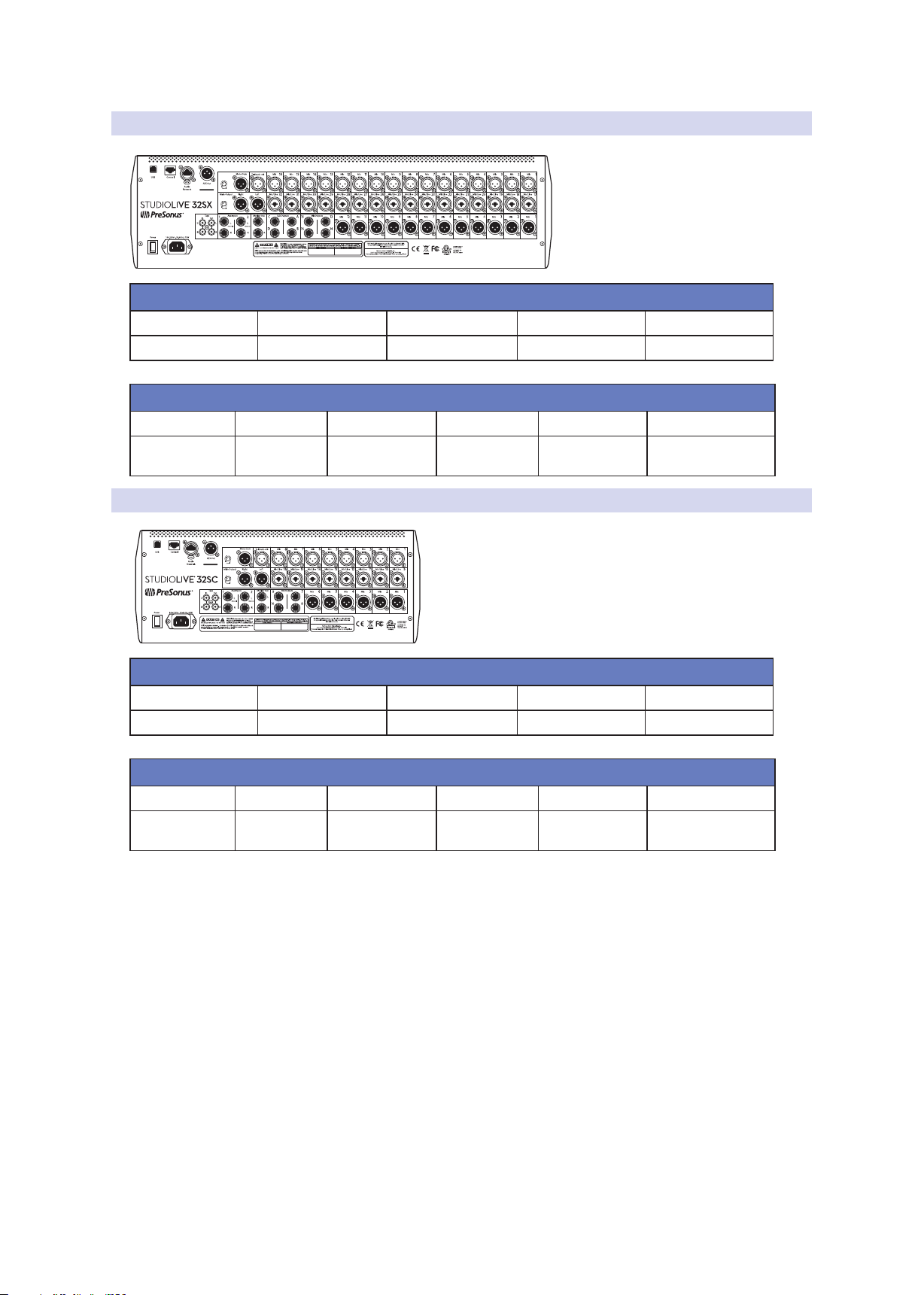
3.1.3 StudioLive 32SX
Analog Inputs
Mic / Line Mic Only Aux Inputs Tape Inputs Talkback In
16 Combo 16 XLR 4 1/4” TRS 2 RCA 1 XLR (F)
Analog Outputs
Flex Mix Subgroup Main Out Mono Sum Monitor Out Tape Out
12 XLR (M)
4 1/4” TRS
4 1/4” TRS 2 XLR (M) 1 XLR (M) 2 1/4” TRS 2 RCA
StudioLive™ Series III
Owner’s Manual
3.1.4 StudioLive 32SC
Analog Inputs
Mic / Line Mic Only Aux Inputs Tape Inputs Talkback In
8 Combo 8 XLR 4 1/4” TRS 2 RCA 1 XLR (F)
Analog Outputs
Flex Mix Subgroup Main Out Mono Sum Monitor Out Tape Out
6 XLR (M)
4 1/4” TRS
N/A 2 XLR (M) 1 XLR (M) 2 1/4” TRS 2 RCA
14
3 Hookup
MANUFACTURING DATE
DESIGNED AND ENGINEERED IN BATON ROUGE, LA, USA • MANUFACTURED IN CHINA • PATENTS PENDING • “STUDIOLIVE”
and “PreSonus” ARE REGISTERED TRADEMARSK OF PRESONUS AUDIO ELECTRONICS • SD LOGO IS A TRADEMARK OF SD-3C, LLC
3.1 Rear Panel Configurations
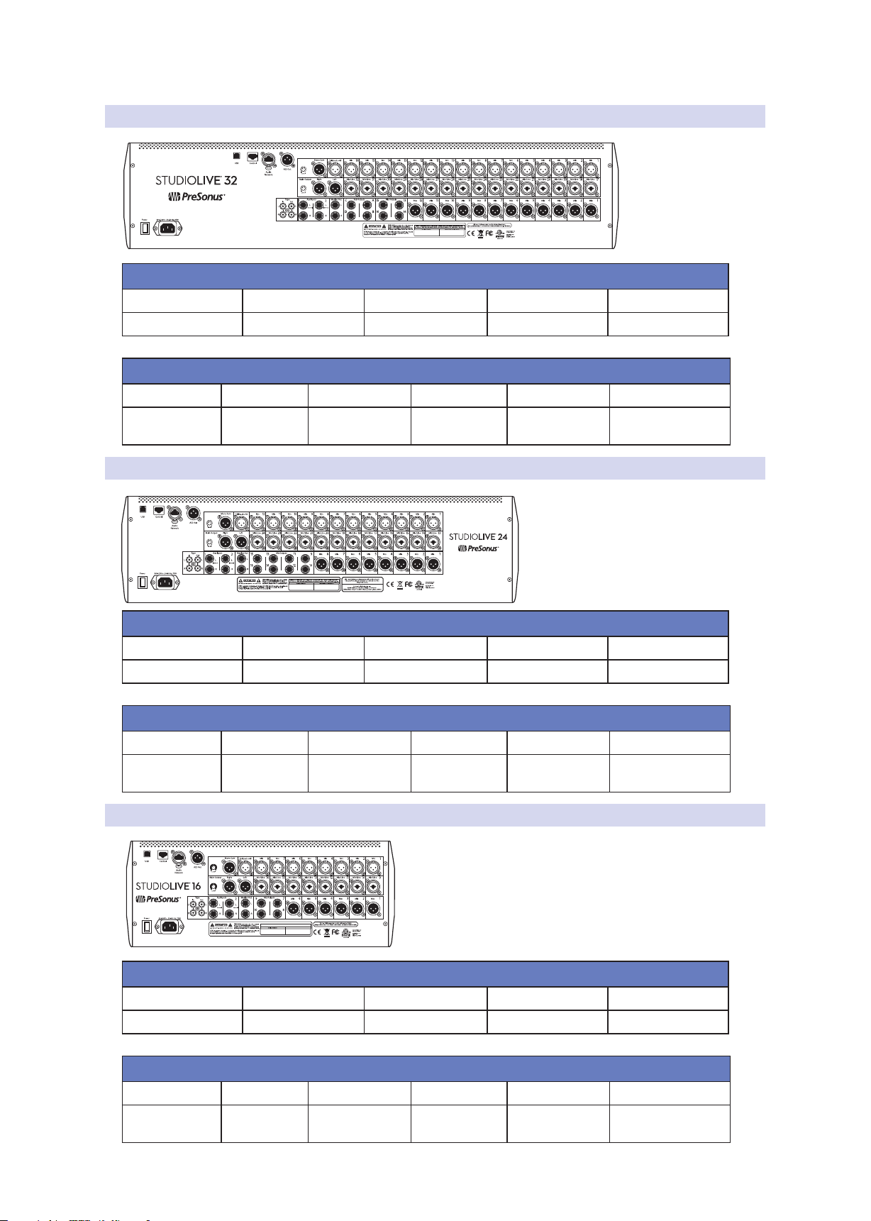
3.1.5 StudioLive 32 (Blue Model)
Analog Inputs
Mic / Line Mic Only Aux Inputs Tape Inputs Talkback In
16 Combo 16 XLR 4 1/4” TRS 2 RCA 1 XLR (F)
Analog Outputs
Flex Mix Subgroup Main Out Mono Sum Monitor Out Tape Out
12 XLR (M)
4 1/4” TRS
4 1/4” TRS 2 XLR (M) 1 XLR (M) 2 1/4” TRS 2 RCA
3.1.6 StudioLive 24 (Blue Model)
StudioLive™ Series III
Owner’s Manual
Analog Inputs
Mic / Line Mic Only Aux Inputs Tape Inputs Talkback In
12 Combo 12 XLR 4 1/4” TRS 2 RCA 1 XLR (F)
Analog Outputs
Flex Mix Subgroup Main Out Mono Sum Monitor Out Tape Out
8 XLR (M)
8 1/4” TRS
n/a 2 XLR (M) 1 XLR (M) 2 1/4” TRS 2 RCA
3.1.7 StudioLive 16 (Blue Model)
Analog Inputs
Mic / Line Mic Only Aux Inputs Tape Inputs Talkback In
8 Combo 8 XLR 4 1/4” TRS 2 RCA 1 XLR (F)
Analog Outputs
Flex Mix Subgroup Main Out Mono Sum Monitor Out Tape Out
6 XLR (M)
4 1/4” TRS
n/a 2 XLR (M) 1 XLR (M) 2 1/4” TRS 2 RCA
15
3 Hookup
3.2 Rear Panel Connections
3.2 Rear Panel Connections
While the complement of analog I/O differs between the various StudioLive Series III
models, the function of each component is consistent across the mixer range.
3.2.1 Analog Inputs
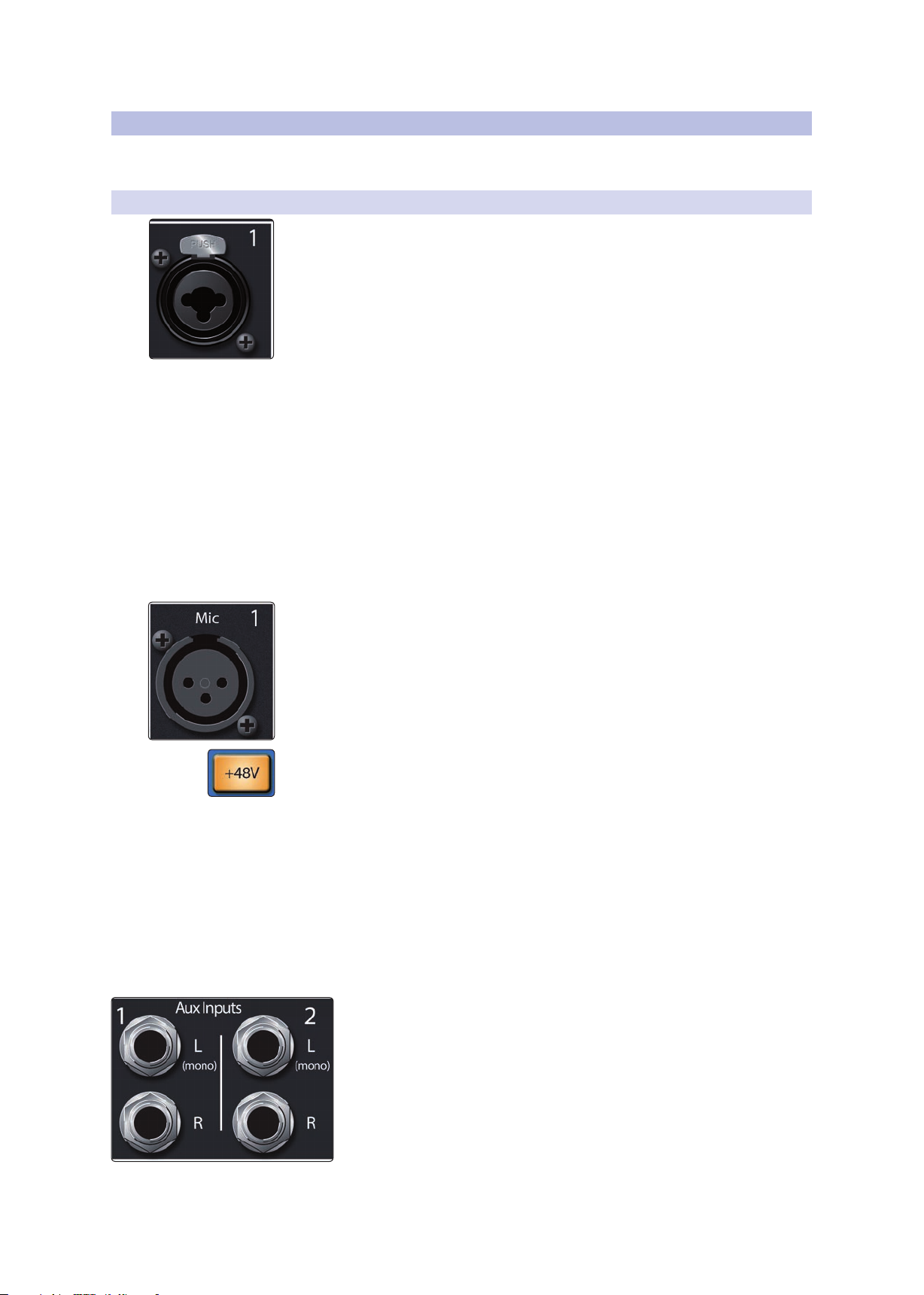
Mic/Line Inputs. Each microphone input on the StudioLive Series III mixers is
supplied with a remote PreSonus XMAX microphone preamplifier, for use with all
types of microphones. The XMAX preamp features a Class A input buffer circuit,
followed by a dual-servo gain stage. This results in exceptionally low noise, and a
wide range of gain, allowing you to boost signals significantly without introducing
unwanted background noise.
It is important to note that the XMAX circuit is an analog design that is remotely
controlled digitally.
Each model is also equipped with a number of inputs that can also accept linelevel signals. These inputs use TRS-XLR combo jacks that can accept both XLR and
balanced or unbalanced 1/4” cables. The ¼-inch TRS connectors bypass the gain
stage and are scaled to accept line-level signals up to +18 dBu.
The StudioLive 64S features locking combo jacks. All other models are equipped with
standard combo connections.
Power User Tip: When the line inputs are engaged, the microphone preamp circuit is
bypassed completely, however, +20 dB of digital gain is available. Typical examples of
line-level connections are synthesizer outputs, signal processors, and stand-alone mic
preamps and channel strips. Use the output level control on your line-level device to
adjust its level.
Microphone Only Inputs. Every model StudioLive Series III mixer, except the
StudioLive 64S, is also provided with Microphone Only inputs. These inputs can only
be used with line level sources connected to a D.I. box.
StudioLive™ Series III
Owner’s Manual
48-volt Phantom Power. The StudioLive provides individually-switchable 48V
phantom power for each microphone input.
WARNING: Phantom power is required for condenser microphones and certain other
specialty microphones that contain active preamp circuitry. However, applying phantom
power to mics that don’t require power can damage them (especially ribbon mics). Switch
phantom power off for all channels where it is not required.
XLR connector wiring for phantom power:
Pin 1 = GND Pin 2 = +48V Pin 3 = +48V
Note: As with many audio devices, plugging a microphone or line-level device, or
enabling/disabling phantom power can create a momentary noise spike in the audio
output of your StudioLive mixer. It is highly recommended that you mute or turn down a
channel’s fader before changing connections or toggling phantom power on or off.
Aux Inputs. The StudioLive offers two balanced stereo auxiliary inputs.
While these line inputs are generally used as effects returns, they can also
be used for any line-level source (synthesizers, amp modelers, etc.). The
left input of each pair is normalled to the right input, so if you are
returning a mono signal to the mix, connect it to the left input, and the
signal will be routed to both sides of the mix.
Power User Tip: More information about using external effects processors
can be found in Section 5.2.3.
16
3 Hookup
3.2 Rear Panel Connections
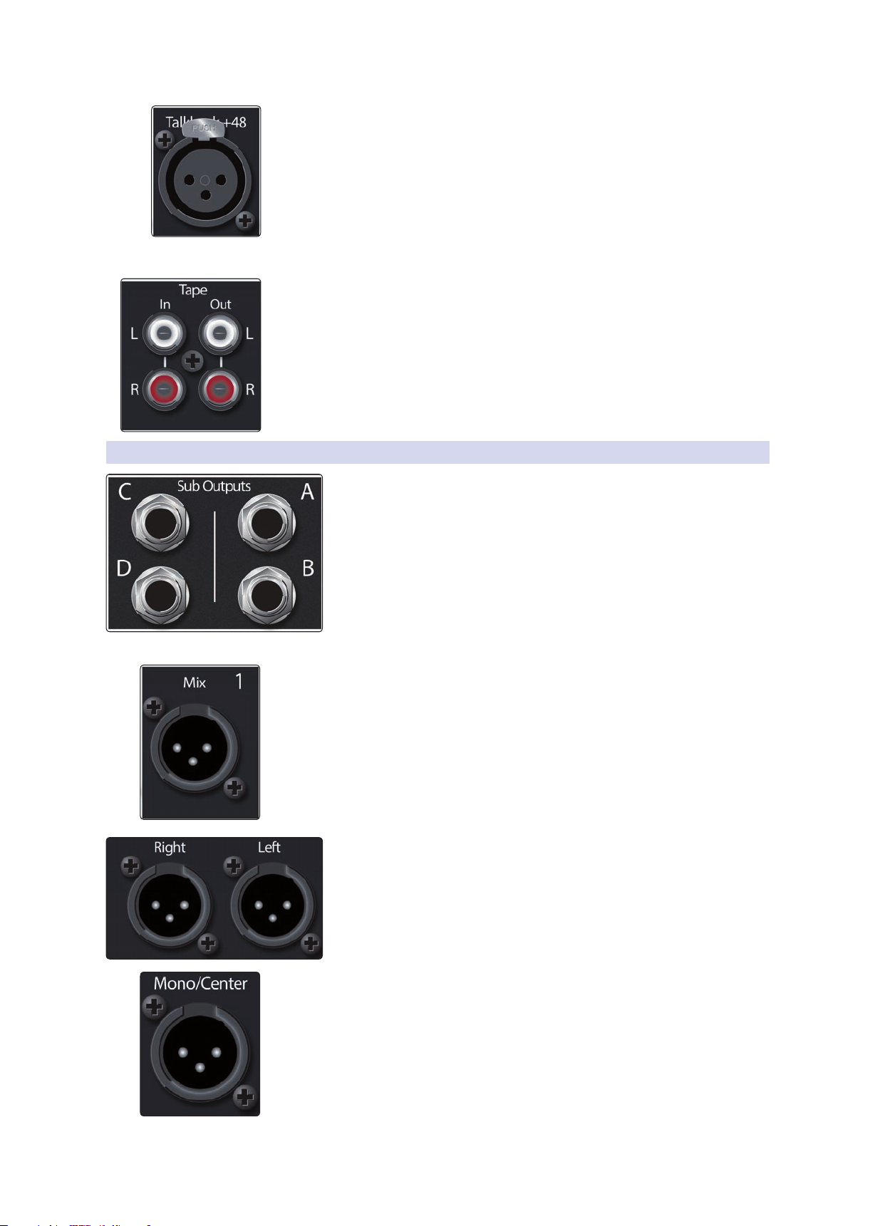
Talkback Mic Input. StudioLive mixers do not have a built-in talkback microphone,
rather they are equipped with an additional XMAX mic preamp to connect an
external microphone for talkback use.
Note: Phantom power is always enabled on the Talkback Mic input. If using a dynamic
mic, we recommend checking its documentation to verify that phantom power will not
harm it.
Power User Tip: The Talkback Mic input uses the same high-quality XMAX mic preamp
employed by the other input channels, and can be enabled as a recording input or as an
additional input channel in any mix.
Tape In/Out. These RCA input and output jacks can be used to connect a music
player (MP3, CD, tape) or other consumer device to your system. The Tape inputs are
an available input source within the mixer, while the Tape outputs mirror the output
of the Main output pair.
3.2.2 Analog Outputs
StudioLive™ Series III
Owner’s Manual
Sub Outputs (StudioLive 32S, StudioLive 32SX, and StudioLive 32
only). These are balanced mono outputs, one for each subgroup.
Power User Tip: While other StudioLive Series III models do not provide
dedicated subgroups outputs, every 32-channel StudioLive Series III is
equipped with four dedicated subgroups in addition to the FlexMixes. These
subgroups can be routed to any FlexMix output, USB send, or routed to other
hardware, like an NSB-series stagebox, over an AVB network. The StudioLive
64S is equipped with 32 FlexMixes, any or all of which can be configured as a
subgroup.
More information about Subgroups can be found in Section 5.3.1.
Mix Outputs. Local analog outputs are provided for the FlexMixes on your
StudioLive Series III mixer. While any FlexMix can be routed to any output, by default,
these mixes are routed in order (i.e. FlexMix 1 to Mix Out 1, FlexMix 2 to Mix Out 2,
etc.)
More information about configuring FlexMixes can be found in Section 5.1.
More information about routing to Mix Outputs can be found in Section 12.3.2.
Main Left / Right Outputs. The StudioLive features stereo main outputs
on XLR connections.
Main Mono Output. A mono output is also provided for the Main Output bus. The
function of this output is model dependent:
• StudioLive 64S. The Mono Output on the StudioLive 64S is equipped with its
own mono bus. This bus can be configured as a mono mix or a center channel
and provides level control for all input independently of the Main Mix bus. When
configured as a Center channel, each channel has a unique center divergence
control. For more information on the StudioLive 64S Mono Bus, please see Section
5.6.
• All other models. For all other StudioLive Series III models, the Mono output is an
analog sum of the Main stereo mix.
17
3 Hookup
3.2 Rear Panel Connections
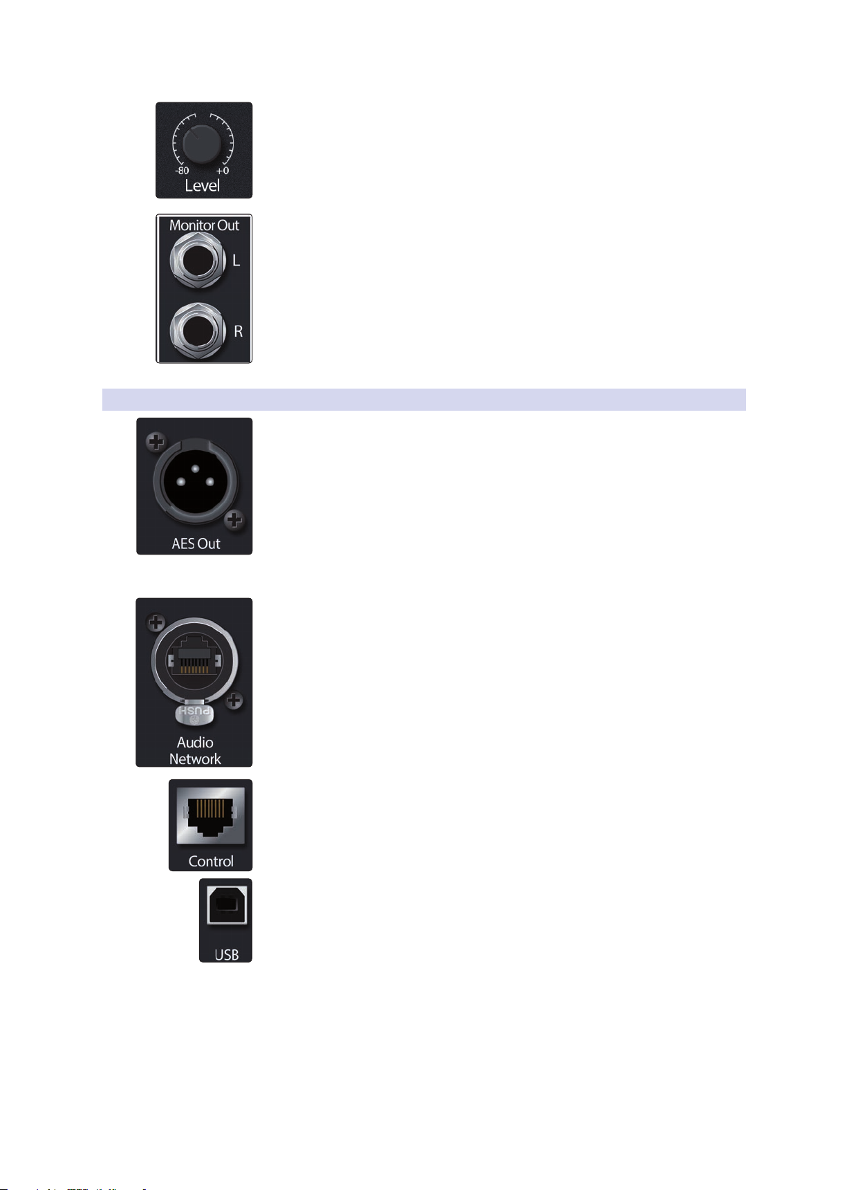
Main / Mono level controls (32-channel models). All 32-channel StudioLive mixer
models are equipped with a level control to adjust the output level at the analog
stage. The Main (stereo) output attenuation control has a range of -80 to 0 dB. The
Mono output level control has a range of -80 to +6 dB.
Note: This feature is not available on the StudioLive 64S
Monitor Outputs. This pair of balanced 1/4” TRS outputs are provided to connect a
pair of monitors in the control room or sound booth. The level is controlled by the
Monitor knob in the Monitors section on the top panel.
3.2.3 Digital and Networking
AES Output. By default, the AES/EBU digital output receives the same signal as the
stereo Main outputs. However, you can route any of the mix buses, Tape input, or the
Solo bus to this output. Because the StudioLive cannot be synced externally, you will
need to use it as the master clock and set your AES-equipped device to receive word
clock externally via AES. Please consult the documentation for your external digital
device for instructions.
Power User Tip: This output can also be connected to S/PDIF-format devices, through the
use of an AES/EBU-S/PDIF adapter. A standard XLR-RCA adapter will not function. AES/
EBU-S/PDIF adapters contain impedance-matching circuitry that is required for proper
function.
Audio Network. This connection accepts both locking XLR Ethernet (e.g. etherCON™)
and RJ45 connections and is used for AVB audio networking.
For more information on AVB networking, see the StudioLive Series III AVB
Networking Guide.
StudioLive™ Series III
Owner’s Manual
Ethernet Port. This RJ45 port is used to connect your StudioLive to a standard LAN
network for control applications only.
For more information on configuring a network for remotely controlling your mixer,
see the StudioLive Series III AVB Networking Guide.
USB Port. This female USB-B jack provides connection to a computer for audio
interfacing, control, and file transfer duties.
18
3 Hookup
3.3 Top Panel Connections
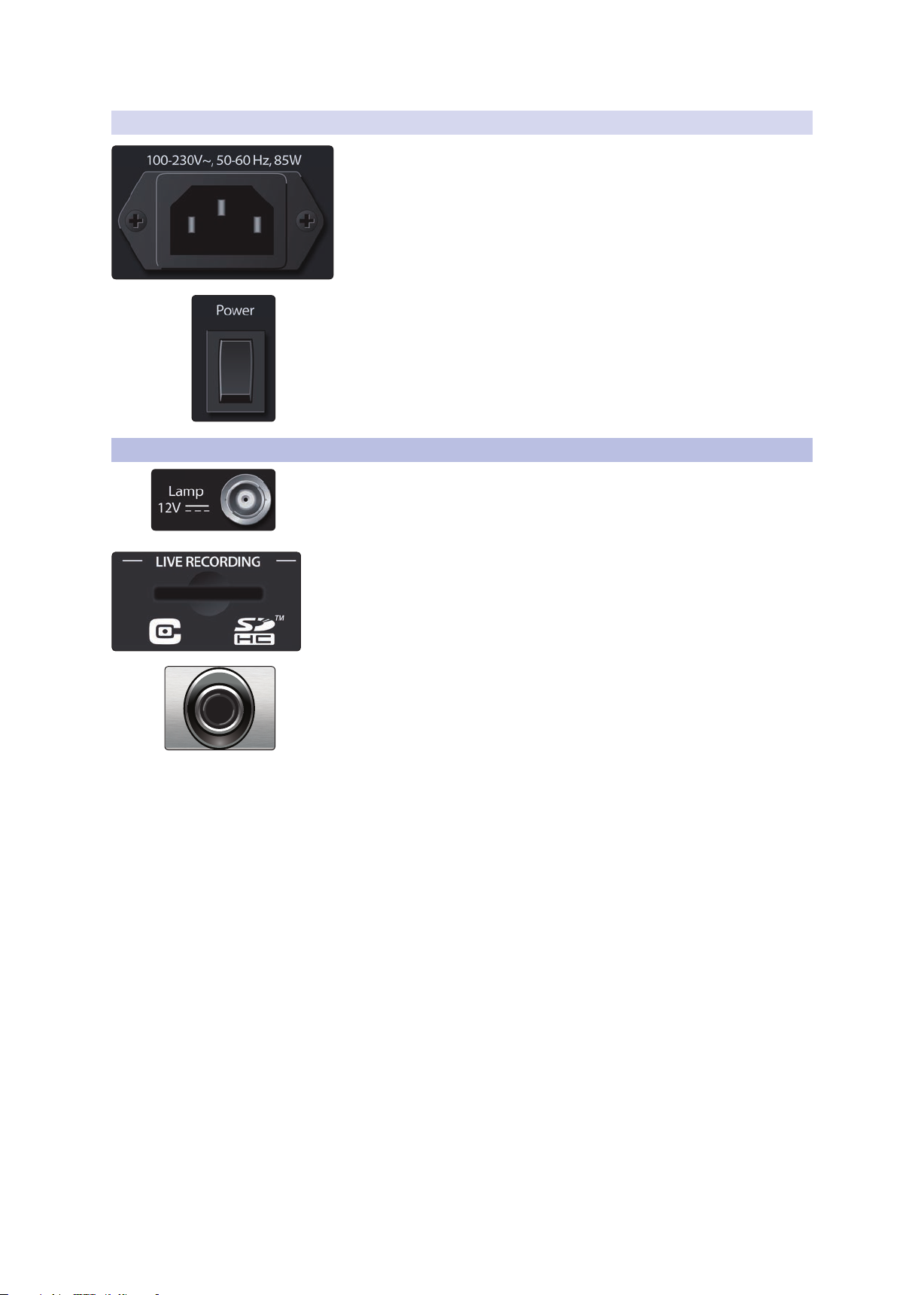
3.2.4 Power
Power Switch. Push the top part of this switch to power your StudioLive on, and the
bottom to switch power off.
Power User Tip: StudioLive Series III mixers provide a Soft Power Down option from the
Home menu. Selecting this option first will store your StudioLive’s current mix state,
allowing you to power it off without losing any settings. You will also be given the option
to log out of the current User Profile.
3.3 Top Panel Connections
Lamp Connector. This 12V BNC connection is provided to connect a third-party
console lamp. Do not use a bulb that is larger than 12V, 380 mA.
StudioLive™ Series III
Owner’s Manual
Power Input. Connect the provided IEC power cable to this input.
SD Card Slot. This slot accepts standard-sized SD cards at capacities up to 32 GB
(SDHC supported). SD cards can be used for audio recording and playback,
transferring Capture 3 session from your computer to your mixer, and firmware
updates.
Headphone Output. On the front of the StudioLive, a 1/4-inch TRS jack is available
for connecting a pair of headphones. Headphone output level is set by turning the
Phones knob in the Monitors section of the mixer. By default, this output receives its
signal from the solo bus, but you can freely assign any mix bus (pre-or-post-fader) as
well as the Tape Input to the Headphone output. See Section 10 for more information.
19
3 Hookup
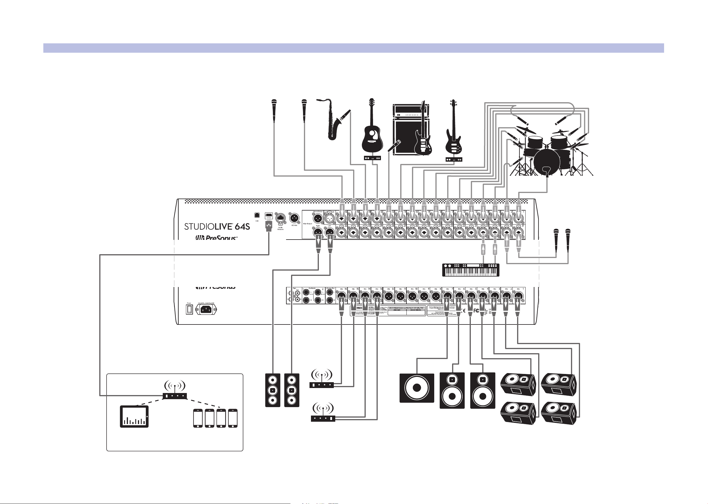
StudioLive control surface
iPad running
UC Surface
Mobile devices
running QMix-UC
wireless router
floor wedges
sidefilldrum monitor
acoustic
guitar/DI
sax
keyboard/DI
lead vocal
backup
vocal mic
backup vocal mics
drum kit
bass/DIelectric guitar amp
front of house
speakers
subwoofer
wireless in-ear
(keys)
wireless in-ear
(lead vocals)
3.4 Typical Band Setup Diagrams
3.4 Typical Band Setup Diagrams
StudioLive™ Series III
Owner’s Manual
20
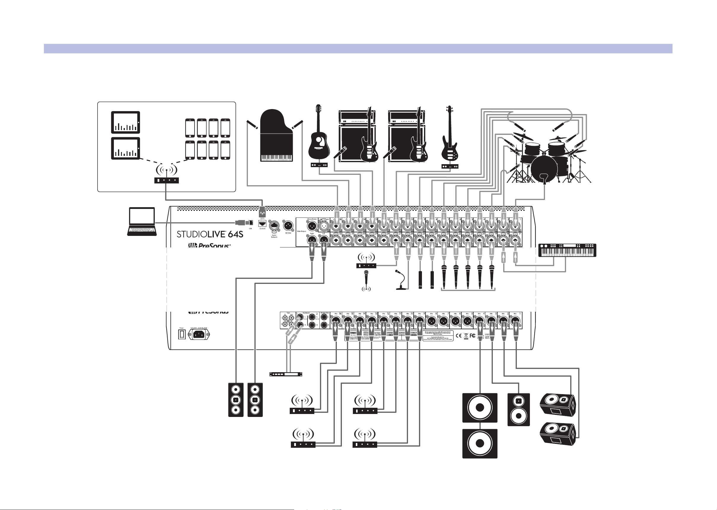
3 Hookup
wireless in-ear
(keys)
wireless in-ear
(lead vocals)
wireless in-ear
(bass)
floor wedges
StudioLive control surface
iPads running
UC Surface
Mobile devices
running QMix-UC
acoustic
guitar/DI
keyboard/DI
lead and backup
vocal mics
drum kit
bass/DIelectric guitar
amp (lead)
electric guitar
amp (rhythm)
subwoofers
wireless router
piano
podium
mic
wireless
roaming mic
hanging
choir mics
laptop running
Capture
dvd player
cry room
front of house
speakers
wireless in-ear
(lead guitar)
3.5 Typical Church Setup Diagrams
3.5 Typical Church Setup Diagrams
StudioLive™ Series III
Owner’s Manual
21
4 Basic Mix Functions Overview
4.1 Channel Strip Basics
4 Basic Mix Functions Overview
StudioLive™ Series III
Owner’s Manual
StudioLive Series III mixers offer many powerful and flexible mixing tools that allow
you to quickly set up and monitor multiple mixes at once and have been designed to
make managing multiple layers of input channels, mix masters, and fader mixes, as
well as navigating even the most complicated systems simple.
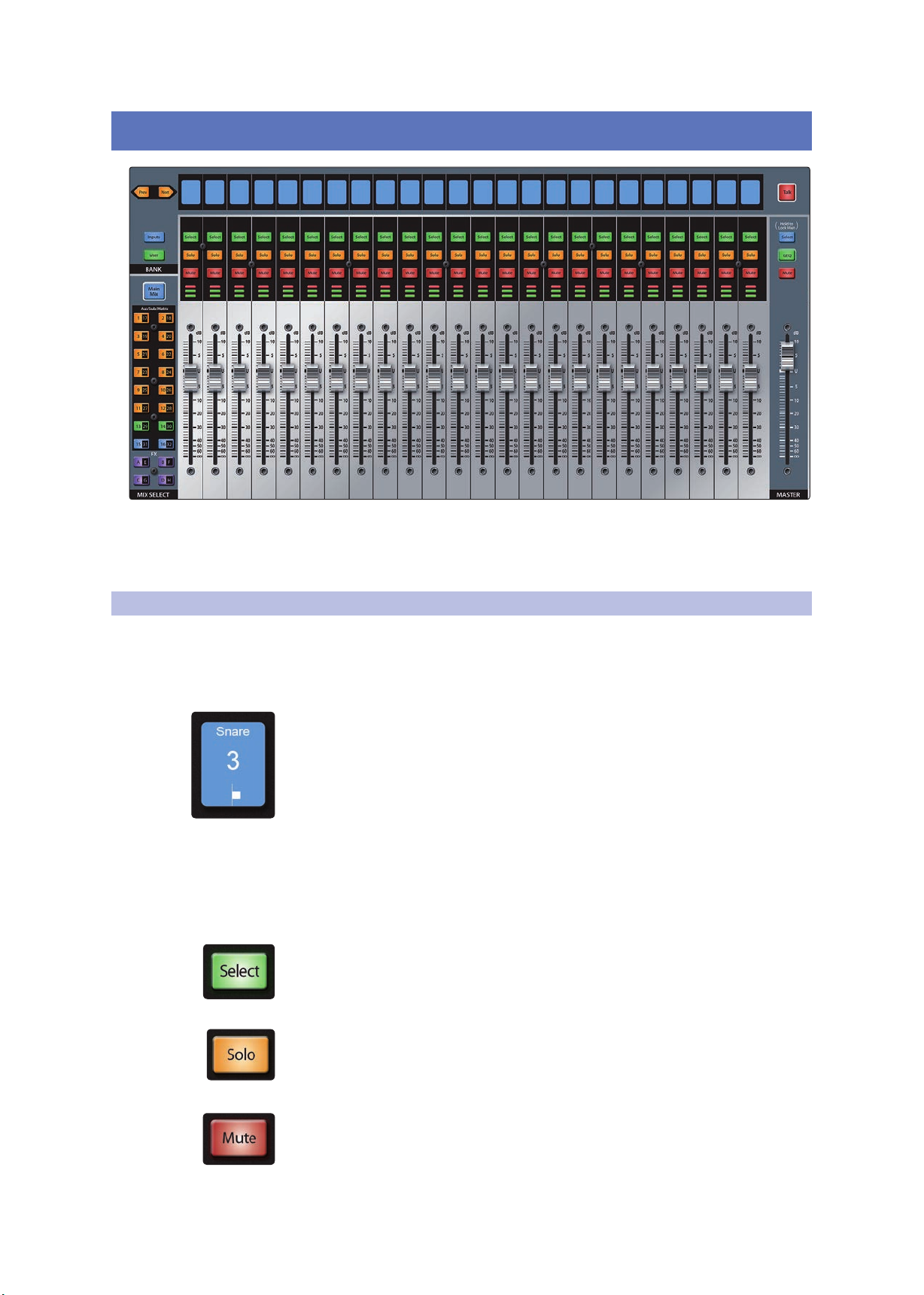
4.1 Channel Strip Basics
If you’ve used a mixer before, the StudioLive channel strip layout should look familiar.
Each channel strip on your StudioLive (apart from the Master) features the following
controls and visual aids:
Scribble Strip Display
This graphical display shows you useful information about the input channel or mix
master that the channel is currently addressing. The following details are displayed:
• Name. Shows the name for the channel currently being controlled by the channel
strip.
• Number. Shows the number and type of the currently being controlled by the
channel strip. Standard inputs are numbered normally. Aux input channels begin
with “A,” Tape inputs with “Tape,” FX returns with “FX,” Aux Bus Masters with “Ax,”
Subgroup Masters with “Sb,” and Matrix Masters with “Mx.”
• Pan Position. Shows the current pan position for the currently being controlled
by the channel strip.
Select Button
Press this button to select a channel or bus to bring its Fat Channel settings into
focus. Select buttons can also be used to add and remove channels from Subgroups,
DCA Filters, and Mute Groups. For more information, see Sections 5.3, 4.3, and 12.1.
Solo Button
This button will solo its channel to the main outputs or to the monitor outputs,
depending on whether AFL/PFL (Pre-Fader Listening) or SIP (Solo In Place) is selected
in the Solo Edit Menu. Please review Section 10.1.1 for details.
Mute Button
Press this button to mute the corresponding channel, mix, or bus.
Press it again to unmute.
22
4 Basic Mix Functions Overview
4.2 Fader Layers and Banks
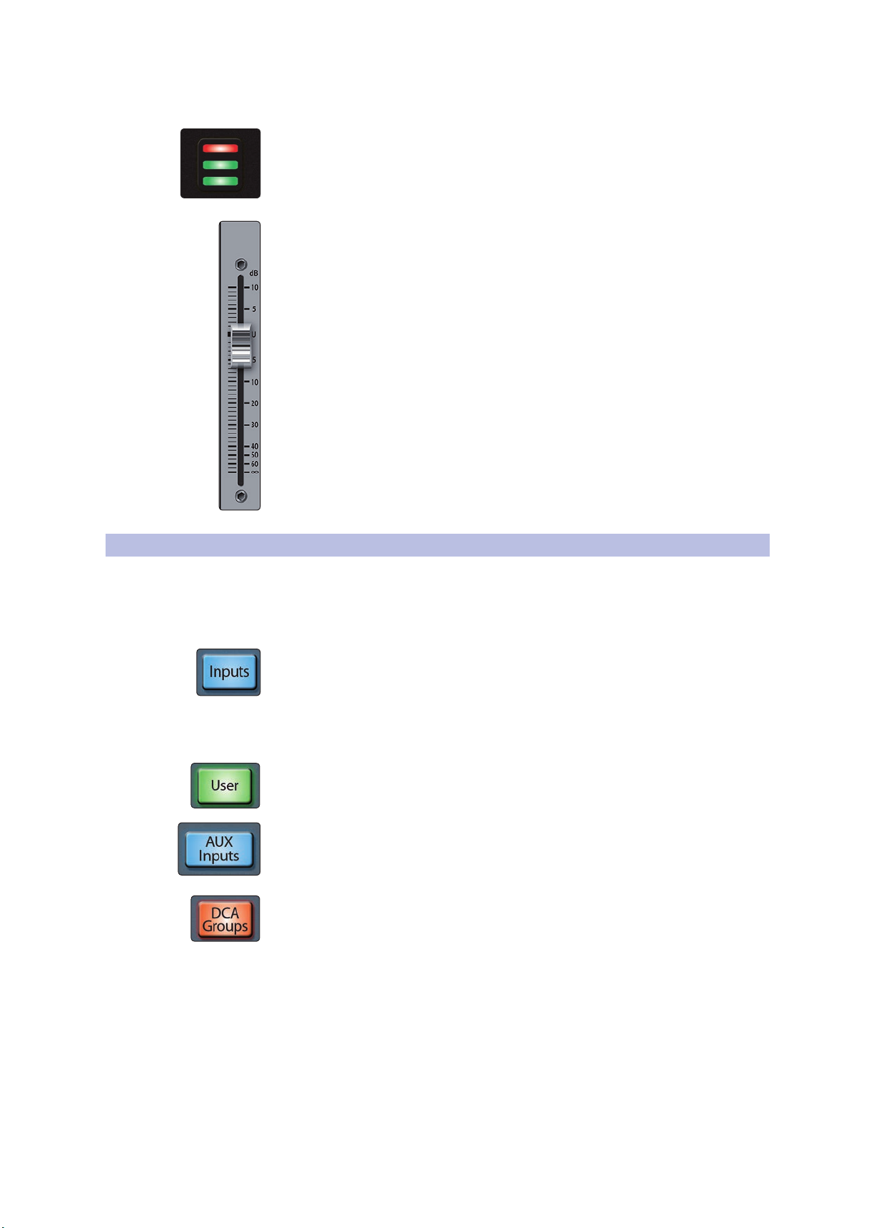
Level Meter
Each channel has a three-segment LED level meter, to provide an indication of the
signal level. The bottom segment illuminates when the signal reaches -40 dBFS. The
middle segment illuminates when the signal reaches -18 dBFS. The top segment will
begin to illuminate red as the input signal approaches clip at -1.5 dBFS. Once the
signal exceeds -0.2 dBFS, the LED will illuminate more brightly.
Channel Fader
This touch-sensitive motorized fader lets you control output volume for the input,
mix, or bus that the channel is currently addressing. When the fader is pulled all the
way down (to the ∞ mark), the signal is muted entirely. At the “U” mark (for unity
gain), the mixer is neither boosting nor attenuating the signal. Settings above “U” add
up to 10 dB of gain.
Power User Tip: Because the channel faders are motorized, you can quickly flip between
mixes and recall mix scenes without needing to manually recall them.
StudioLive™ Series III
Owner’s Manual
4.2 Fader Layers and Banks
With so many available analog and digital inputs, mixes, buses, and DCAs, your
StudioLive has more internal mix elements than it does channel strips to control
them. This is where fader layers come in.
You can switch between these layers using the following buttons:
Inputs. This displays the input channels across all faders. By default, each local analog
input is routed to the corresponding channel (i.e. Input 1 is routed to Channel 1, etc.),
however, any local analog input or network source can be routed to each channel.
For more information on Digital Patching, see Section 12.3.
For a more detailed overview of default analog routing, please review the table in
Section 14.2.1.
User. The User layer allows you to create a custom selection of channels for quicker
access. For more information on the User layer, see Section 4.2.1.
Aux Inputs. While active, the eight channel strips to the right of the Master fader
control FX Returns A-D, Aux Input 1 & 2, Tape Input, and Talkback. The channel strips
to the left of the Master fader continue to address input channels as normal. Note: this
control is not available on the StudioLive 32SC and StudioLive 16.
DCA Groups. Each of the 24 DCA Groups is equipped with a group master control.
Press Prev and Next buttons to bank through the 24 DCA Groups. When enabled, the
group masters are available from your StudioLive control surface as follows:
• StudioLive 64S, StudioLive 32S, StudioLive 32SX, StudioLive 32, and
StudioLive 24. The 8 channel strips to the right of the Master fader control the
Filter DCA Group masters.
• StudioLive 32SC and StudioLive 16. The DCA Group masters are available on the
channel faders.
Power User Tip: In addition to the 24 user-definable DCA groups, your StudioLive mixer
will automatically create DCA groups for channels that are placed within the same
category (Drums, Guitar, etc). These Auto DCA groups will populate below the userdefinable groups.
23
4 Basic Mix Functions Overview
Inputs
User
Main
Mix
Solo
Mute
Select
Solo
Mute
Select
1
17 18
19 20
21 22
3
5
2
4
6
23 247 8
25 269 10
4.2 Fader Layers and Banks
Mix/FX Masters. When enabled, the master level for Subgroups, FlexMixes, and FX
buses are available from your StudioLive control surface as follows:
• StudioLive 64S, StudioLive 32S, StudioLive 32SX, StudioLive 32, and
StudioLive 24. The 8 channel strips to the right of the Master fader control the
bus masters.
• StudioLive 32SC and StudioLive 16. The bus masters will be available on the
channel faders.
Press the Prev and Next buttons to scroll through the other available input channels
and output buses.
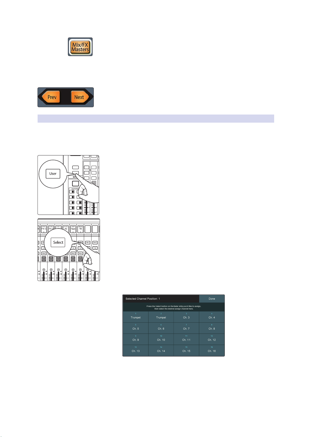
4.2.1 User Fader Layer
The User layer lets you choose a selection of channels that are visible when you press
the User button. This can be useful to access crucial channels quickly, especially in
mixes with high channel counts.
To assign channels to the User layer, do the following.
1. Navigate to the User layer by pressing the User button.
StudioLive™ Series III
Owner’s Manual
2. Press Select on a channel strip to which you wish to assign a mixer channel
or any unused channel in the user layer.
3. The User Layer Assignment screen will be displayed on the Touch Display.
4. Select the channel of your choice on the Touch Display to assign it to the
channel strip of your choice.
5. Repeat steps 2-4 as necessary to populate the User layer with your most
needed channels.
6. Press Done when finished.
24
4 Basic Mix Functions Overview
4.3 Filter DCA Groups
To Edit the User layer, press and hold the Select button for the channel for which
you’d like to change the assignment. This will open the User Layer Assignment
screen. From here you can unassign the channel completely or change the channel
assigned to it.
Power User Tip: Every channel, mix master, and DCA group master is available to assign
to the User Layer. Use the encoder below the Touch Display to navigate through all the
available options.
4.3 Filter DCA Groups
Professional mixing consoles have addressed the problem of managing complex
mixes with population groups that reduce the channels you’re viewing at one time
and DCAs that control the overall level of a group of channels.
We’ve combined the best aspects of these solutions with Filter DCAs. A Filter DCA
can contain any combination of the available input channels and effects returns. You
can even include the same channel in multiple Filter DCAs so you can manage mixes
in multiple ways. Each group is given a master level control so you can control the
overall level of the group while maintaining each channel’s relative balance in the
mix. In this way, for example, you can create a single fader to control every drum in a
monitor mix and maintain the relative level of the drum mix that you created.
Once selected, a Filter DCA group stays active until exited regardless of which mix is
selected. This allows you to adjust the group independently across different mixes.
You can also flip between groups on the fly to change the view of a selected mix.
You can create up to 24 Filter DCA Groups.
When controlling the master level of a DCA Group, the faders for the channels
assigned to that group will move to more accurately provide a visual indication of the
actual level of each channel in the group.
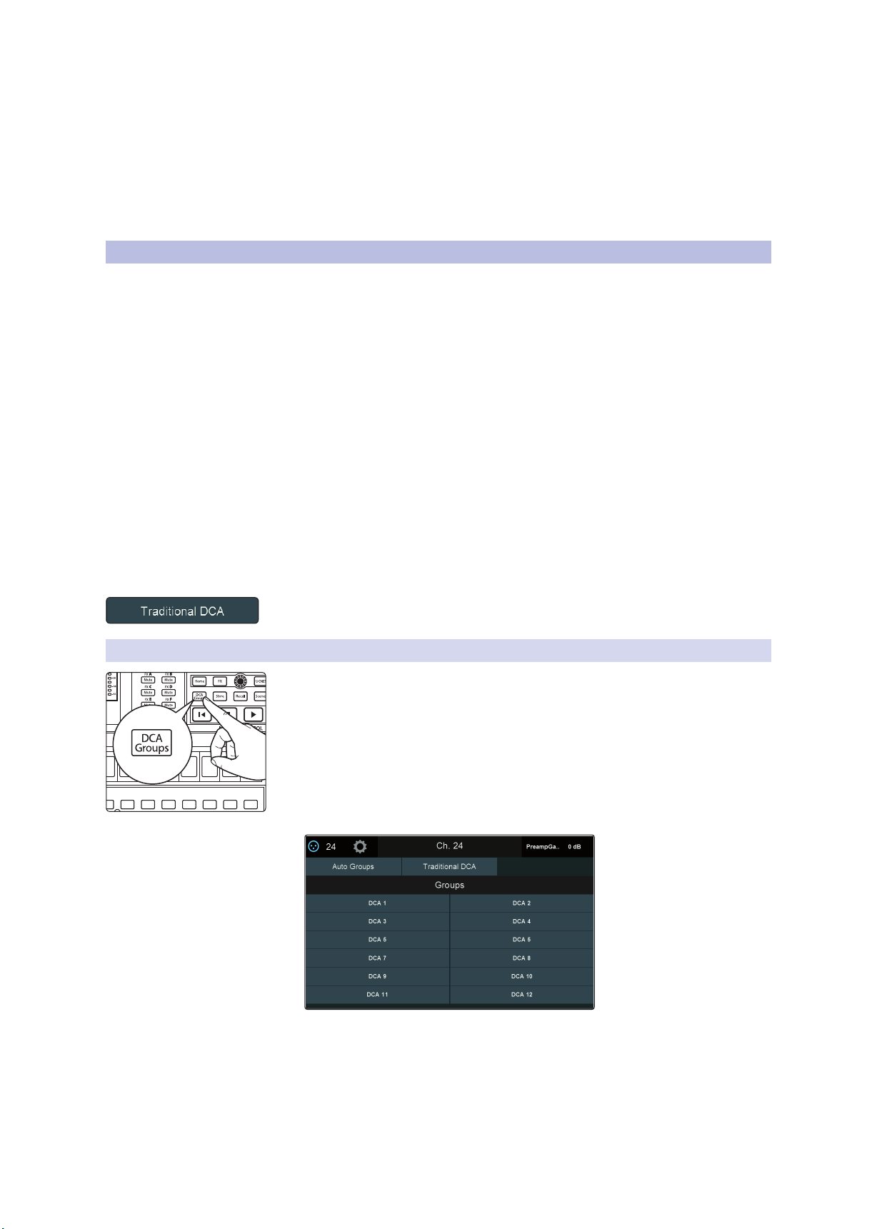
This feature can be defeated by enabling “Traditional DCA” mode from the Filter DCA
Group edit screen.
StudioLive™ Series III
Owner’s Manual
4.3.1 Creating Filter DCAs
1. To create a new Filter DCA Group, press the DCA Groups button in the Master
Control section.
2. This will open the Filter DCA Group edit screen.
3. Select the DCA Group you’d like to use.
25
 Loading...