

Presonus StudioLive 24 Series III Owner’s Manual
StudioLive™ Series III
Digital Mix Console / Recorder with Motorized Faders
Owner’s Manual
®
www.presonus.com
English

Table of Contents
1 Overview — 1
4.7 FX Buses — 29
4.7.1 Creating Internal Bus FX Mixes — 29
4.8 Fixed Subgroups — 30
1.1 Introduction — 1
1.2 About this Manual — 1
1.3 Feature Summary — 2
1.4 What’s in the Box — 3
2 Getting Started — 4
2.1 Level Setting Procedure — 4
2.2 Useful Concepts — 8
2.2.1 Select Buttons and the Fat Channel — 8
2.2.2 FlexMixes — 9
2.2.3 Fader Layers — 9
2.2.4 DCA Groups — 9
2.2.4 Recording and Playback — 9
3 Hookup — 10
3.1 Rear Panel Connections — 10
3.2 Top Panel Connections — 13
3.3 Typical Band Setup Diagrams — 14
3.4 Typical Church Setup Diagrams — 15
4.9 Talkback System — 30
4.9.1 Talkback Edit Screen — 31
5 The Fat Channel — 32
5.1 Fat Channel Navigation — 33
5.1.1 Input Mode — 34
5.1.2 Gate Mode — 37
5.1.3 Compressor Mode — 40
5.1.4 EQ Mode — 45
5.1.5 Aux Sends Mode — 50
5.1.6 User Mode — 51
5.2 Fat Channel Meters — 52
5.3 Input Source Selection — 52
5.4 Mic/Line Channel Buttons — 52
5.5 Output Assignment Buttons — 53
5.6 A/B Comparison for EQ
and Dynamics Settings — 54
5.7 Stereo Link — 54
5.8 Copy/Paste & Preset Load/Save — 55
4 Basic Mixing and Routing — 16
4.1 Channel Strip Basics — 16
4.2 Fader Layers and Banks — 17
4.3 User Fader Layer — 18
4.4 Filter DCA Groups — 19
4.4.1 Creating Filter DCAs — 19
4.4.2 Editing or Deleting
a Filter DCA Group — 20
4.4.3 Managing DCA Group Masters — 20
4.5 Main Meters — 20
4.6 FlexMixes — 20
4.6.1 Aux Mixes — 21
4.6.2 Subgroups — 25
4.6.3 Matrix Mixes — 28
6 Tape Controls — 57
6.1 Pairing a Bluetooth Device — 57
7 SD Recording — 58
7.1 Creating a New Session for Recording — 58
7.2 Loading a Session for Playback — 59
7.3 Capture Screen — 60
7.3.1 Recording Status Messages — 61
7.3.2 Transport Controls — 61
7.4 Sound Check Button — 62
8 Master Control — 63
8.1 Home Button Features — 63
8.1.1 System Screen — 64

8.1.2 Global Lockout — 68
11.4 EQ Frequency Guides — 96
8.1.3 Utilities — 69
8.1.4 Audio Routing — 69
8.2 FX — 71
8.2.1 Digital XL Reverb — 71
8.2.2 335 Digital Reverb — 72
8.2.3 PAE-16 Digital Reverb — 72
8.2.4 Vintage Plate Reverb — 73
8.2.5 Mono Delay — 73
8.2.6 Stereo Delay — 74
8.2.7 Pingpong Delay — 74
8.3 UCNET — 75
8.3.1 IP Address Settings — 75
8.3.2 Permissions — 75
8.4 DAW Button — 75
8.5 Scenes — 76
11.5 EQ Setting Suggestions — 97
11.6 Using Input Delay — 99
11.6.1 Aligning the Backline
with Vocal Mic — 100
11.6.2 Aligning Direct and Mic’d Signals — 101
11.7 Using Output Delay — 101
11.7.1 Front-of-House — 102
11.7.2 Delay Systems — 102
11.7.3 Aligning Subs to Mains — 104
11.8 Effect Types — 104
11.8.1 Reverb and its Parameters — 104
11.8.2 Delay and its Parameters — 105
11.8.3 Chorus and Flange — 106
11.9 Technical Specifications — 107
11.10 Block Diagrams — 108
8.5.1 S1: Zero Out (Board Reset) — 76
8.5.2 Nulling Parameters — 77
8.5.3 Creating and Recalling a Scene — 78
9 Monitoring Controls — 80
9.1 Solo Controls — 80
9.1.1 Solo Modes — 81
9.1.2 Using the Solo Bus for Monitoring — 82
9.1.3 Using Solo in Place to Set Up a Mix — 83
10 Graphic EQ — 85
10.1 Assigning GEQs — 86
10.2 Using the GEQ — 86
10.3 GEQ Presets — 87
10.4 Using the RTA to Ring Out Monitors — 87
12 Troubleshooting
and Warranty — 109
12.1 Troubleshooting — 109
13 Warranty Information — 110
13.1 How Consumer Law Relates
To This Warranty — 110
13.2 PreSonus Products
And EU Statutory Warranty — 110
13.3 What This Warranty Covers — 110
13.4 Exclusions and Limitations — 110
13.5 Who This Warranty Protects — 111
13.6 How Long This Warranty Lasts — 111
13.7 What PreSonus Will Do — 111
13.8 How to Get Warranty Service (USA) — 111
11 Resources — 89
11.1 Networking Overview — 89
11.1.1 Wired Ethernet Control Setup — 90
11.2 Stereo Microphone Placement — 91
11.3 Compression Setting Suggestions — 94
13.9 How to Get Warranty Service
(outside of USA) — 111
13.10 Limitation of Implied Warranties — 111
13.11 Exclusion of Damages — 112

1 Overview
1.1 Introduction
1 Overview
1.1 Introduction
StudioLive™ Series III
Owner’s Manual
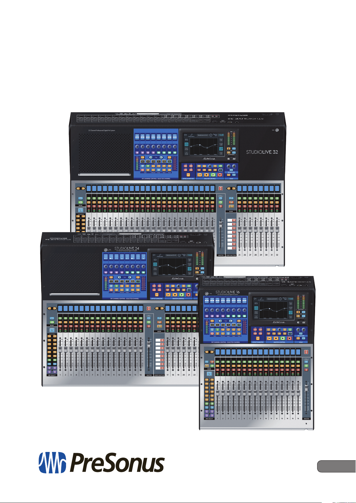
Thank you for purchasing your PreSonus® StudioLive™ Series III Digital Mixer.
PreSonus Audio Electronics has built your StudioLive mixer with high-grade
components to ensure optimum performance for many years to come. Loaded with
32, 24, or 16 high-headroom XMAX™ microphone preamplifiers, a built-in 38x38 USB
recording and playback interface, powerful Fat Channel signal processing, highquality effects, extensive routing and submixing, talkback, and more, StudioLive
Series III breaks new boundaries for music performance and production. All you need
is a compatible computer with a USB connection or an SD card, a few microphones
and cables, speakers, and your instruments, and you are ready to record in the studio
or in front of a live audience!
We encourage you to contact us with questions or comments regarding this product.
PreSonus Audio Electronics is committed to constant product improvement, and
we value your suggestions highly. We believe the best way to achieve our goal
of constant product improvement is by listening to the real experts: our valued
customers. We appreciate the support you have shown us through the purchase of
this product.
1.2 About this Manual
We suggest that you spend some time with this manual before starting to work with
your StudioLive Series III mixer, to familiarize yourself with its features, workflows, and
connection procedures. This will help your setup process go as smoothly as possible.
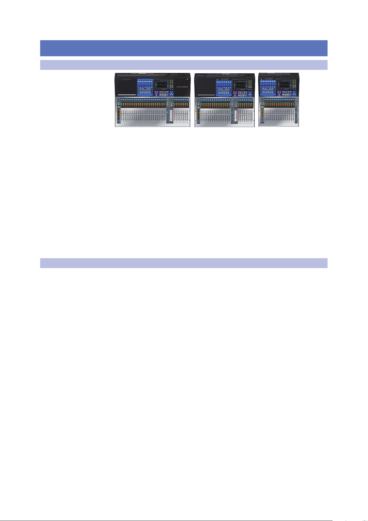
This manual applies to all StudioLive Series III mixers. While all three StudioLive Series
III mixers provide exactly the same mixing capabilities internally, their input and
output configuration differs. Where these differences occur, the StudioLive 32 will be
listed first, followed by the StudioLive 24, and then the StudioLive 16.
A separate manual, contains information about the StudioLive Series III Software
Library, as well as instructions for connecting and using your StudioLive Series III
mixer with a computer.
Throughout this manual, you will find Power User Tips, providing mixing tricks
(some of which are uniquely suited to the StudioLive Series III), and explanations
of various useful audio terms. Near the end of this manual, you’ll find a selection of
audio tutorials, covering everything from microphone placement to recommended
equalizer and compression settings. We hope these tutorials help you to get the most
from your StudioLive Series III mixer.
Thank you, once again, for purchasing our product. We are confident that you will
enjoy your new StudioLive.
1

1 Overview
1.3 Feature Summary
1.3 Feature Summary
StudioLive™ Series III
Owner’s Manual
General Controls
• 33/25/17 touch-sensitive, motorized faders
• RGB Select buttons with user-assignable colors
• Transport control
• All-new Fat Channel controls including:
- 8 scribble strips, encoders, and multicolor buttons
- Customizable user layer
- 7-inch color touchscreen
Inputs and Outputs
• 40/32/22 total inputs
• 16/10 FlexMix outputs
• Bluetooth™ 4.1 wireless tape input
• Stereo AES/EBU digital output
• 2 XLR (L/R) Main outputs
• XLR Main summed mono output
• 2 TRS monitor outputs
• Stereo headphone output
Channels and Buses
• 32/24/16 input channels with recallable XMAX Class A mic preamps
• 2 stereo aux inputs
• 16 FlexMixes, 4 fixed Subgroups
• 4 internal effects sends
• Stereo main bus
• 24 Filter DCAs for flexible control of multiple channels
Recording
• Onboard 34x34 SD recorder
• 38x38 USB recording interface
• 55x55 AVB recording interface
Digital
• Studio-quality converters with 115 dB dynamic range
• 48 kHz operation with 24-bit resolution
• UC Surface touch control software for macOS®, Windows®, and iPad®
• Studio One® Pro digital audio workstation and mastering software for macOS and
Windows (StudioLive 32)
• Studio One® Artist digital audio workstation software for macOS and Windows
(StudioLive 24 and16)
• Capture™ multitrack recording software for macOS and Windows
• QMix®-UC aux-control software for iOS® and Android™ available free from Apple
App Store, Google Play, and Amazon App Store
2
1 Overview
1.4 What’s in the Box
1.4 What’s in the Box
StudioLive™ Series III
Owner’s Manual
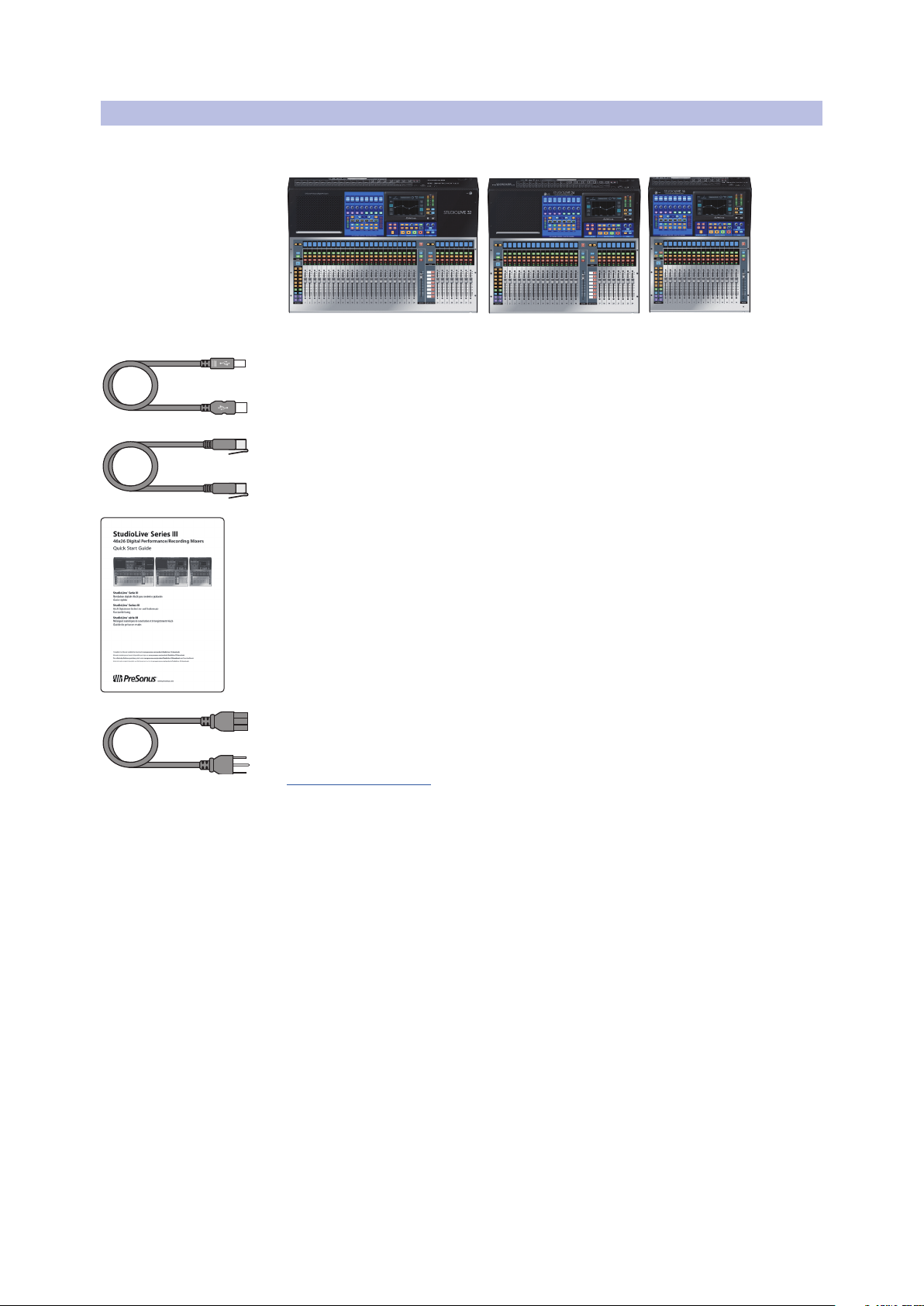
In addition to a Visual Quick Start Guide, your StudioLive package contains the
following:
• PreSonus StudioLive Series III digital recording and performance mixer
• 1 meter USB cable
• 1 meter CAT6 Ethernet cable
• StudioLive Series III Quick Start Guide
• IEC power cord
Power User Tip: All companion software and drivers for your PreSonus StudioLive Series
III mixer are available for download from your My PreSonus user account. Please visit
http://my.presonus.com and register your StudioLive Series III mixer to receive downloads
and licenses.
3
2 Getting Started
2.1 Level Setting Procedure
2 Getting Started
Before you begin, here are a few rules to get you started:
• Always turn down the Main fader and both the Monitor and Phones knobs in the
Monitor section before making connections.
• Before plugging or unplugging a microphone while other channels are active,
mute the channel to which you are connecting.
• Your faders should be set on or near the “U” mark whenever possible. The “U”
indicates unity gain, meaning the signal is neither boosted nor attenuated. If the
main output of your StudioLive is too high or too low when your faders are at or
near unity, you can use the output-level knob on the rear panel of the StudioLive
to adjust the level up or down until you have achieved the optimal volume.
• Do not allow your inputs to clip. Watch the level meters; when signal nears
Clipping, the top LED illuminates, indicating that the analog-to-digital converters
are in danger of being overdriven. Overdriving the converters will cause digital
distortion, which has a negative effect on sound quality.
Your P.A. and studio equipment should be powered on in the following order:
• Sound sources (keyboards, direct boxes, microphones, etc.) connected to the
StudioLive inputs
• StudioLive Series III mixer
• Computer (if applicable)
• Power amplifiers or powered loudspeakers
When it is time to power down, your system should be turned off in the reverse
order. Now that you know what not to do, let’s get started!
StudioLive™ Series III
Owner’s Manual
2.1 Level Setting Procedure
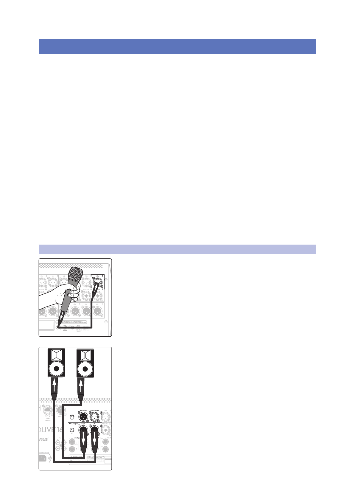
1. Plug a microphone into the Channel 1 input on your StudioLive Series III
with a standard XLR cable.
2. Connect the main outputs of your StudioLive to your powered monitors (or
power amp if using passive speakers).
4
2 Getting Started
2.1 Level Setting Procedure
StudioLive™ Series III
Owner’s Manual
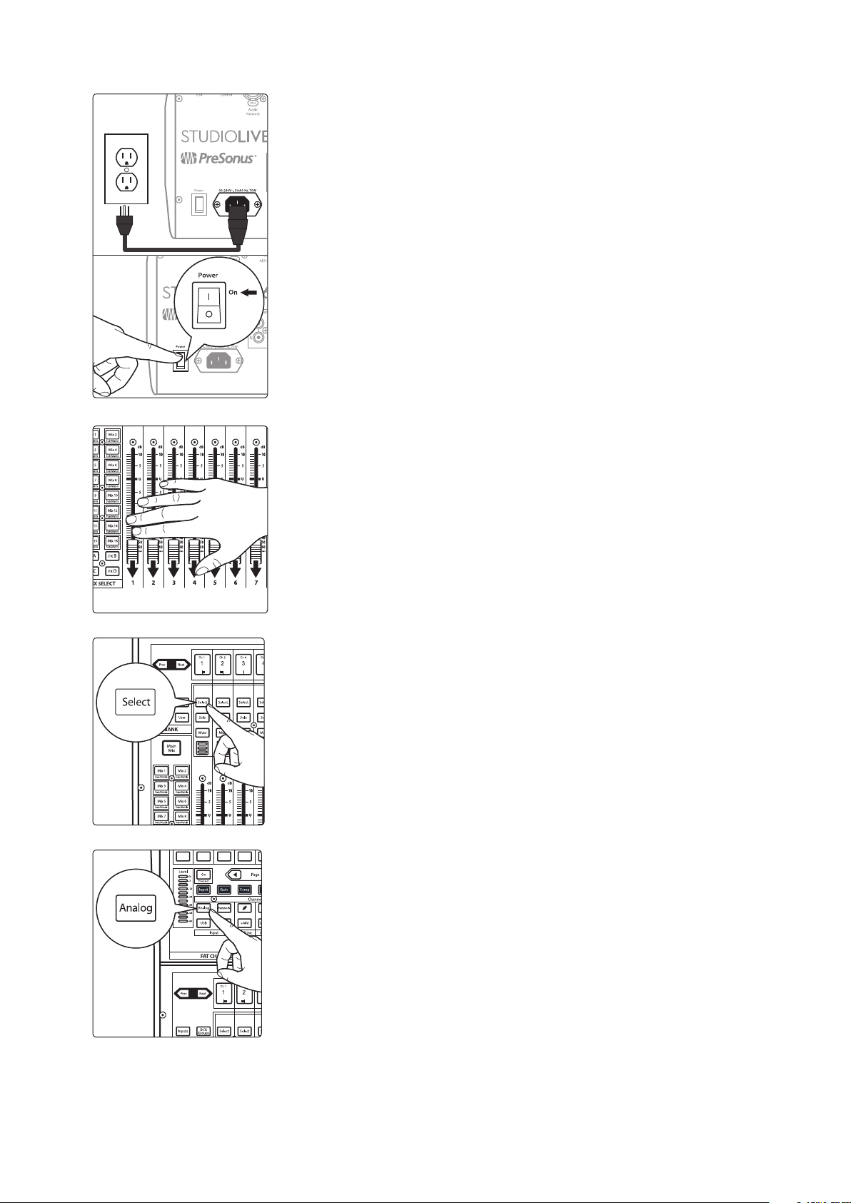
3. Plug your StudioLive into a power outlet and turn it on.
4. Move all of the faders on your StudioLive down to the lowest setting.
5. Press the Select button on Channel 1 to bring it into focus in the
Fat Channel.
6. Press the Analog button in the Fat Channel to patch in the analog input.
5
2 Getting Started
2.1 Level Setting Procedure
StudioLive™ Series III
Owner’s Manual
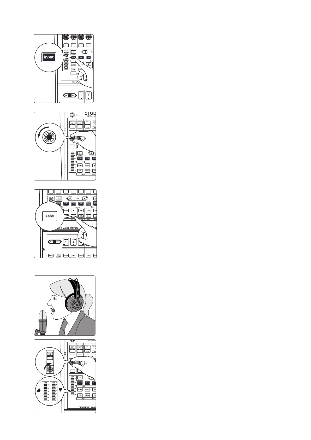
7. Press the Input button in the Fat Channel.
8. Turn the first knob in the Fat Channel section (Preamp Gain) counterclockwise to its lowest setting.
9. If your microphone requires phantom power, press the +48v button in the
Fat Channel.
10. Turn on your powered monitors or power amp.
11. Speak or sing into your microphone at the same volume
as the performance.
12. Turn the first knob in the Fat Channel section (Preamp Gain) clockwise while
watching the Level (input) meter in the Fat Channel. Adjust the Preamp
Gain knob until the meter shows an average level around the middle of its
range. Avoid lighting the red (clip) LED at the top of the meter.
6
2 Getting Started
2.1 Level Setting Procedure
StudioLive™ Series III
Owner’s Manual
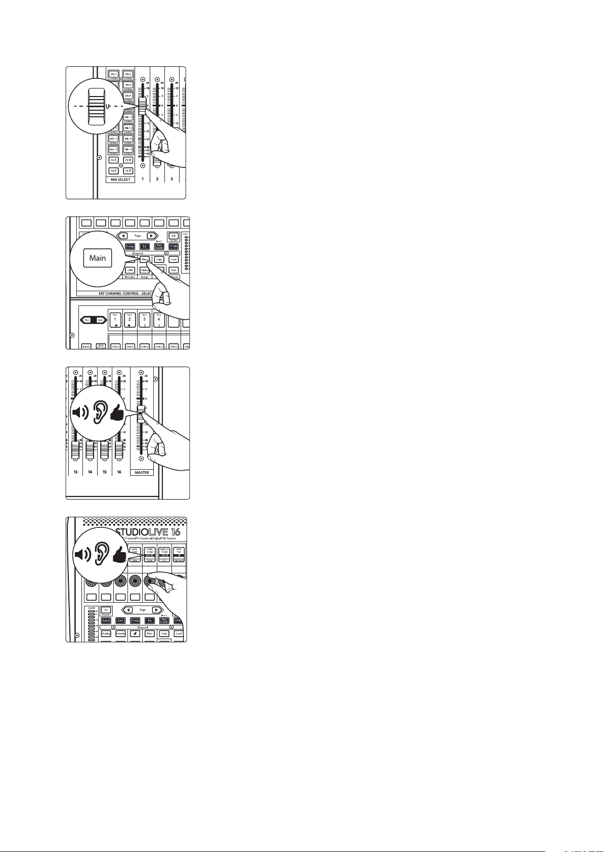
13. Raise the Channel 1 fader to its “U” setting (unity gain).
14. Press the “Main” button in the Fat Channel to assign Channel 1 to the Main
output bus.
15. Raise the Main fader while singing or speaking into the microphone until
you are satisfied with output level.
16. Use the Fat Channel controls to add dynamics processing and EQ
as needed.
7

2 Getting Started
LIMITERCOMPGATEPANHI PASSPREAMP
Gain Filter Thresh
Gate Comp Lim Dig SendCenter
Thresh Thresh Post
DAW DELAY
0.0 msoff0.00 dB0.00 dB-84.00 dB< C >off0 dB
2.2 Useful Concepts
2.2 Useful Concepts
This section covers some basic workflow concepts to help you to more quickly get
acquainted with your StudioLive.
2.2.1 Select Buttons and the Fat Channel
All around the StudioLive, you will see Select buttons. There is a Select button on
each channel as well as the master fader. Each of these buttons serves exactly the
same purpose: to access the available Fat Channel parameters for its channel or bus.
These buttons will also change colors to alert you as to the type of mix you are
viewing (Aux, Subgroup, or Matrix)
StudioLive™ Series III
Owner’s Manual
The Fat Channel is the heart of the StudioLive. It gives you a wealth of powerful signal
processing, mixing, and configuration tools to help you make the most of your mixer.
Each channel and mix in your StudioLive can take advantage of the Fat Channel
functions at the touch of the corresponding Select button.
The 8 multipurpose knobs, buttons, and Scribble Strip displays in the Fat Channel
shift their functions to suit your needs as you move between tasks. The integrated
touchscreen works in tandem, providing useful information and fluid touch control.
For more information on using the Fat Channel system, see Section 5.
8

2 Getting Started
2.2 Useful Concepts
2.2.2 FlexMixes
2.2.3 Fader Layers
StudioLive™ Series III
Owner’s Manual
In a traditional analog console, there are several different types of buses, each
feeding a dedicated output. Your StudioLive mixer features 16/10 analog Mix
outputs, each driven by a FlexMix bus. Why do we call them FlexMixes? Because each
FlexMix can be configured as any one of four bus types:
• Pre- or Post-Fader Send Aux Bus. Aux buses provide auxiliary mixes that are
separate from the main and subgroup mixes.
• Subgroup. Subgroups are alternate buses that act much like the Main L+R bus on
your StudioLive.
• Matrix Mix. Matrix mixes provide auxiliary mixes created from any bus output as
well as every input channel.
What’s more, FlexMixes can be stereo linked or used as mono, providing
maximum flexibility.
Note: Like the StudioLive 32 and StudioLive 24, the StudioLive 16 provides 16 Flex Mixes.
The last six of which can be routed to an AVB network.
For more information on using and configuring FlexMixes, see Section 4.6
To provide the most compact form factor, the StudioLive mixer utilizes fader layers.
Each layer allows you to view the channel strip controls for the input channels in each
mix. Additional fader layers allow you to view just the Aux Inputs, the DCA Group
outputs, or the Mix Master outputs.
More information about Fader Layers can be found in Section 4.2 and 4.3.
2.2.4 DCA Groups
Filter DCA Groups are a way to control the overall volume of a group of related
channels (such as all drum channels). While you can accomplish a similar result by
routing channels to a subgroup and controlling their volume with the subgroup
master, DCA Filter Groups require no such re-routing and offer some additional utility.
For more information on using DCA Filter Groups, see Section 4.4.
2.2.4 Recording and Playback
The StudioLive Series III mixers are equipped with a multi-track SD recorder that
allows you to record all input channels plus the main bus. This SD recorder is
completely integrated with your mixer and is designed to simplify recording and
playback. Playback channels from the SD card can be switched individually
per channel.
In addition to the onboard SD recorder, a USB audio interface is also included. This
interface is continuously bidirectional, allowing you to use plugins as inserts as well
as recording and playback applications.
More information about SD recording and playback is available in Section 7.
More information on USB recording and playback is available in the StudioLive
Software Library Reference Manual.
9
3 Hookup
3.1 Rear Panel Connections
3 Hookup
3.1 Rear Panel Connections
StudioLive™ Series III
Owner’s Manual
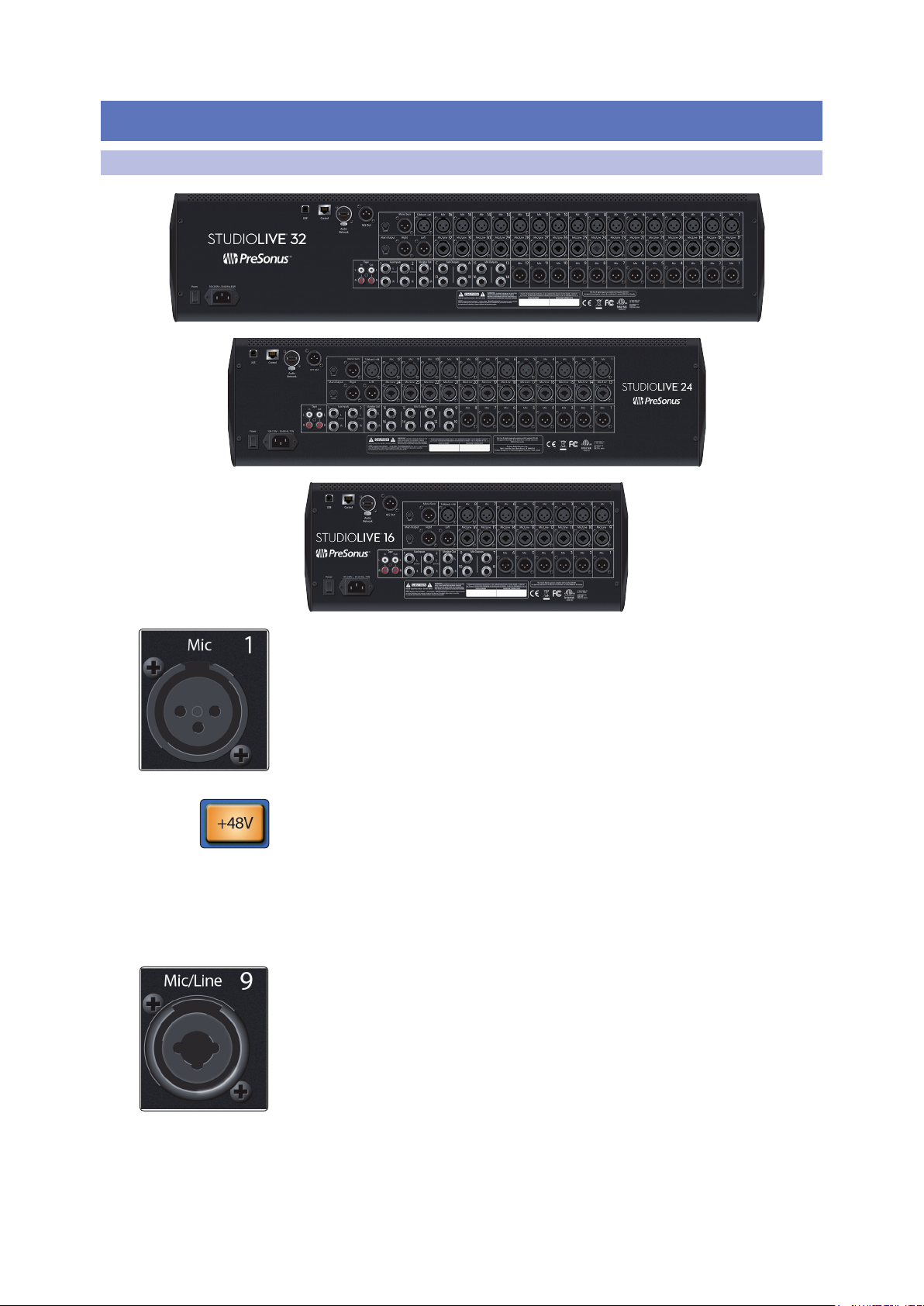
Microphone Inputs. Your StudioLive Series III mixer is supplied with 32/24/16
PreSonus XMAX microphone preamplifiers, for use with all types of microphones. The
XMAX preamp features a Class A input buffer circuit, followed by a dual-servo gain
stage. This results in exceptionally low noise, and a wide range of gain, allowing you
to boost signals significantly without introducing unwanted background noise.
48-volt Phantom Power. The StudioLive provides individually-switchable 48V
phantom power for each microphone input.
WARNING: Phantom power is required for condenser microphones and certain other
specialty microphones that contain active preamp circuitry. However, applying phantom
power to mics that don’t require power can damage them (especially ribbon mics). Switch
phantom power off for all channels where it is not required.
XLR connector wiring for phantom power:
Pin 1 = GND Pin 2 = +48V Pin 3 = +48V
Mic/Line Inputs. Half of the microphone inputs on your StudioLive can also accept
line-level signals. These inputs use TRS-XLR combo jacks that can accept both XLR
and balanced or unbalanced 1/4” cables. The ¼-inch TRS connectors bypass the gain
stage and are scaled to accept line-level signals up to +18 dBFS.
Power User Tip: When the line inputs are engaged, the microphone preamp circuit is
bypassed completely, and no trim control is available. Typical examples of line-level
connections are synthesizer outputs, signal processors, and stand-alone mic preamps
and channel strips. Use the output level control on your line-level device to adjust its level.
Note: As with many audio devices, plugging a microphone or line-level device, or
enabling/disabling phantom power can create a momentary noise spike in the audio
output of your StudioLive mixer. It is highly recommended that you mute or turn down a
channel’s fader before changing connections or toggling phantom power on or off.
10
3 Hookup
3.1 Rear Panel Connections
Mix Outputs. Your StudioLive features 16/16/10 Mix Outputs. Given the flexible
nature of these mix buses, the Mix Outputs may be used to output Aux, Subgroup, or
Matrix mixes. Your StudioLive is equipped with 12/8/6 XLR Mix Outputs and 4/8/4
balanced ¼” TRS Mix Outputs.
Power User Tip: More information about configuring mixes can be found in Section 4.6.
StudioLive™ Series III
Owner’s Manual
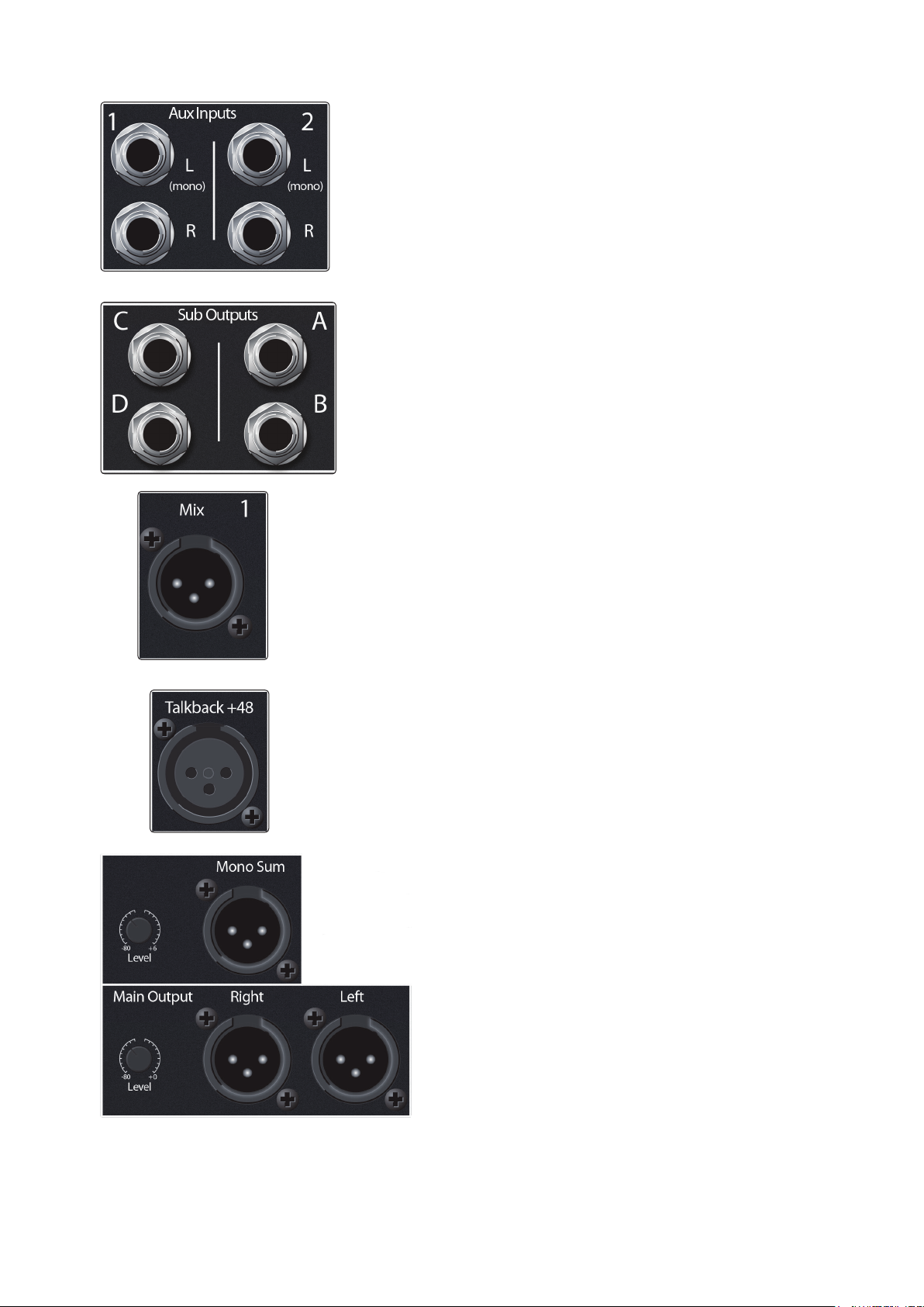
Aux Inputs. The StudioLive offers two balanced stereo auxiliary inputs.
While these line inputs are generally used as effects returns, they can also
be used for any line-level source (synthesizers, amp modelers, etc.). The
left input of each pair is normalled to the right input, so if you are
returning a mono signal to the mix, connect it to the left input, and the
signal will be routed to both sides of the mix.
Power User Tip: More information about using external effects processors
can be found in Section 4.6.1.2.
Sub Outputs (StudioLive 32 only). These are balanced mono outputs,
one for each subgroup.
Power User Tip: While the StudioLive 24 and16 do not provide dedicated
outputs, it does provide four subgroups that can be routed to the AVB network.
More information about Subgroups can be found in Section 4.6.2.
Talkback Mic Input. The StudioLive does not have a built-in talkback microphone, so
an external mic must be used. Phantom power is always enabled on the Talkback Mic
input, so either a dynamic or condenser mic can be used. However, if using a dynamic
mic, we recommend checking its documentation to verify that phantom power will
not harm it.
Power User Tip: The Talkback Mic input uses the same high-quality XMAX mic preamp
employed by the other input channels, and can be enabled as a recording input.
Main Outputs. The StudioLive features both stereo and
mono-summed main outputs, on XLR jacks. A level control is
provided for both sets of outputs. The Main (stereo) output
level control has a range of -80 to 0 dB. The Mono Sum
output level control has a range of -80 to +6 dB.
Power User Tip: Both the stereo and mono-summed Main
outputs are active at all times.
11
3 Hookup
3.1 Rear Panel Connections
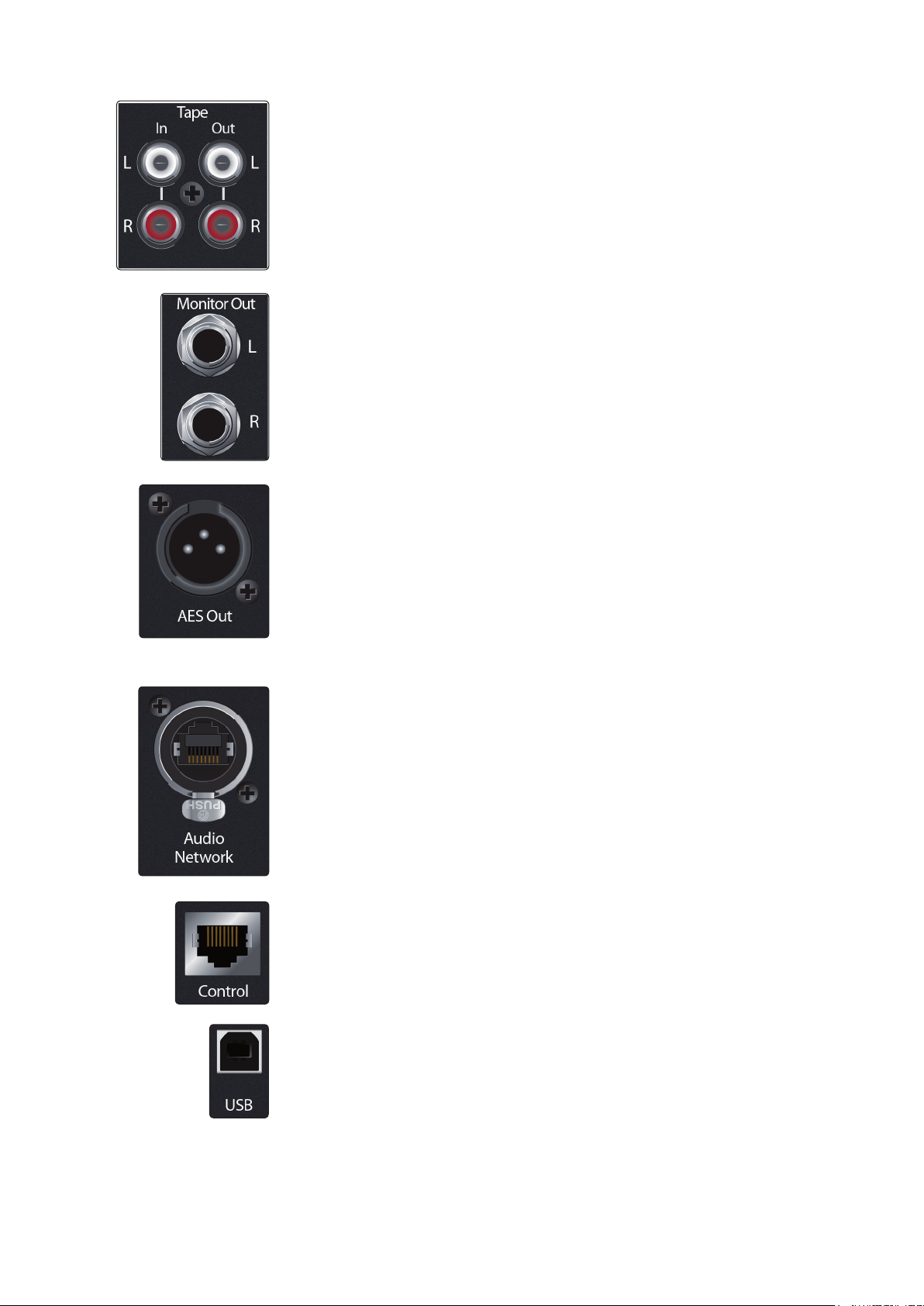
Tape In/Out. These RCA input and output jacks can be used to connect a music
player (MP3, CD, tape) or other consumer device to your system. The Tape inputs are
an available input source within the mixer, while the Tape outputs mirror the output
of the Main output pair.
Monitor Outputs. This pair of balanced TRS outputs are intended to be connected to
a pair of monitors in the control room or sound booth. The level is controlled by the
Monitor knob in the Monitors section on the top panel.
AES Output. By default, the AES/EBU digital output receives the same signal as the
stereo Main outputs. However, you can route any of the mix buses, Tape input, or the
Solo bus to this output. Because the StudioLive cannot be synced externally, you will
need to use it as the master clock and set your AES-equipped device to receive word
clock externally via AES. Please consult the documentation for your external digital
device for instructions.
Power User Tip: This output can also be connected to S/PDIF-format devices, through the
use of an AES/EBU-S/PDIF adapter. A standard XLR-RCA adapter will not function. AES/
EBU-S/PDIF adapters contain impedance-matching circuitry that is required for proper
function.
Audio Network. This connection accepts both Ethercon and RJ-45 connections and
is used for AVB audio networking.
StudioLive™ Series III
Owner’s Manual
Ethernet Port. This RJ-45 port is used to connect your StudioLive to a standard LAN
network for control applications only.
Power User Tip: More information about AVB and control networking can be found in
Section 11.1.
USB Port. This female USB-B jack provides connection to a computer for audio
interfacing, control, and file transfer duties.
12
3 Hookup
3.2 Top Panel Connections
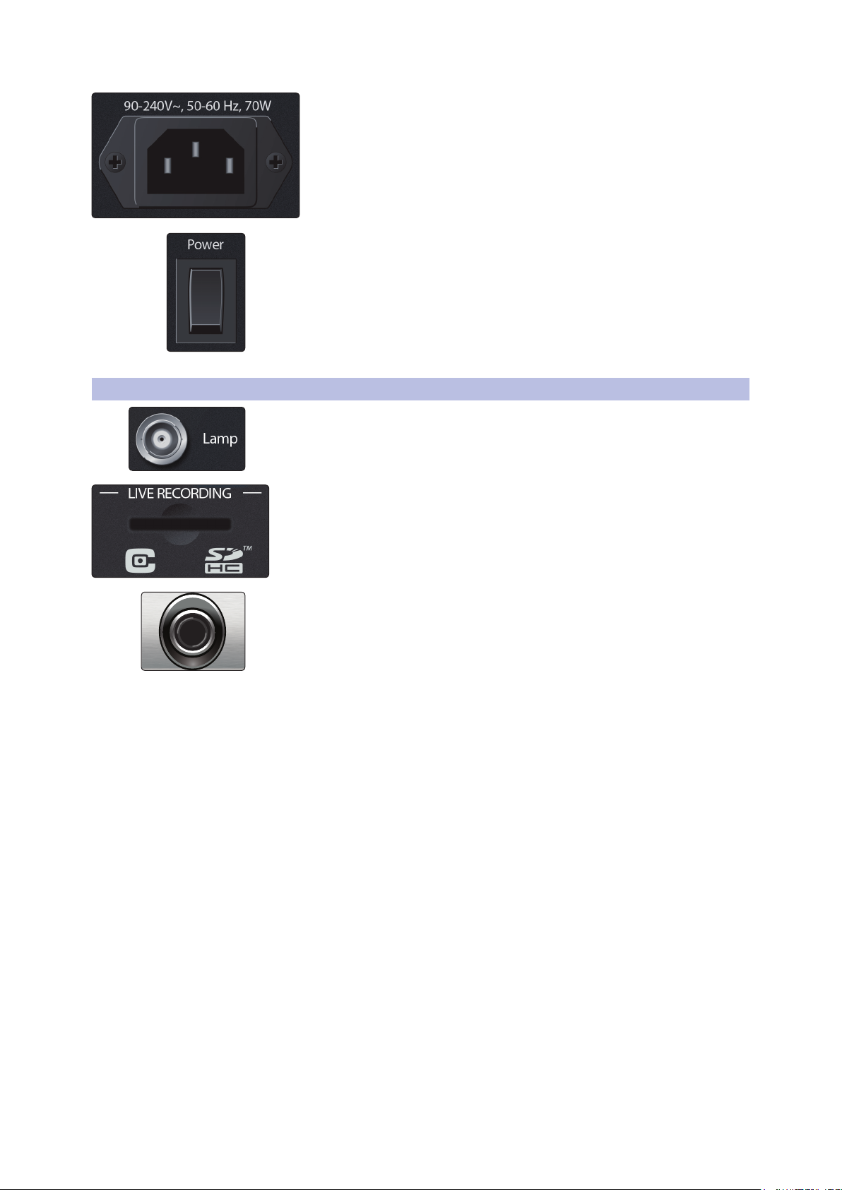
Power Switch. Push the top part of this switch to power your StudioLive on, and the
bottom to switch power off.
3.2 Top Panel Connections
Lamp Connector. This 12V BNC connection is provided to connect a third-party
console lamp. Do not use a bulb that is larger than 12V, 380 mA.
StudioLive™ Series III
Owner’s Manual
Power Input. Connect the provided IEC power cable to this input.
SD Card Slot. This slot accepts standard-sized SD cards at capacities up to 32 GB
(SDHC supported). SD cards can be used for audio recording and playback,
storage and recall of mixer settings, and firmware updates.
Headphone Output. On the front of the StudioLive, a 1/4-inch TRS jack is available
for connecting a pair of headphones. Headphone output level is set by turning the
Phones knob in the Monitors section of the mixer. By default, this output receives its
signal from the solo bus, but you can freely assign any mix bus (pre-or-post-fader),
USB Digital Return, or audio network input to the Headphone output. See Section 9
for more information.
13
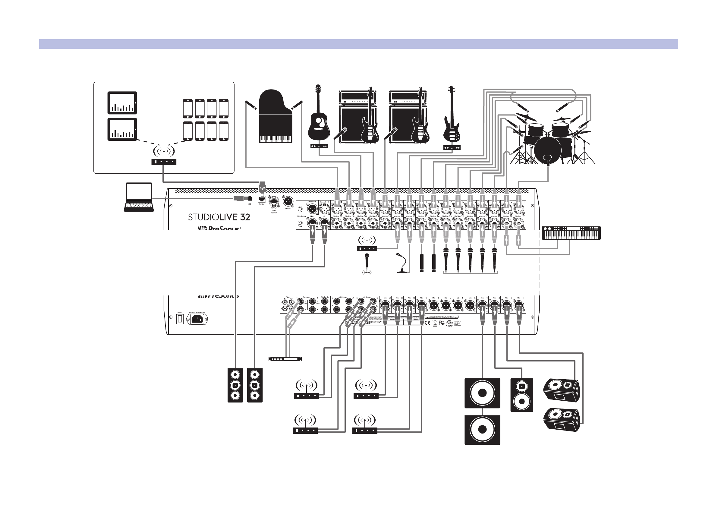
3 Hookup
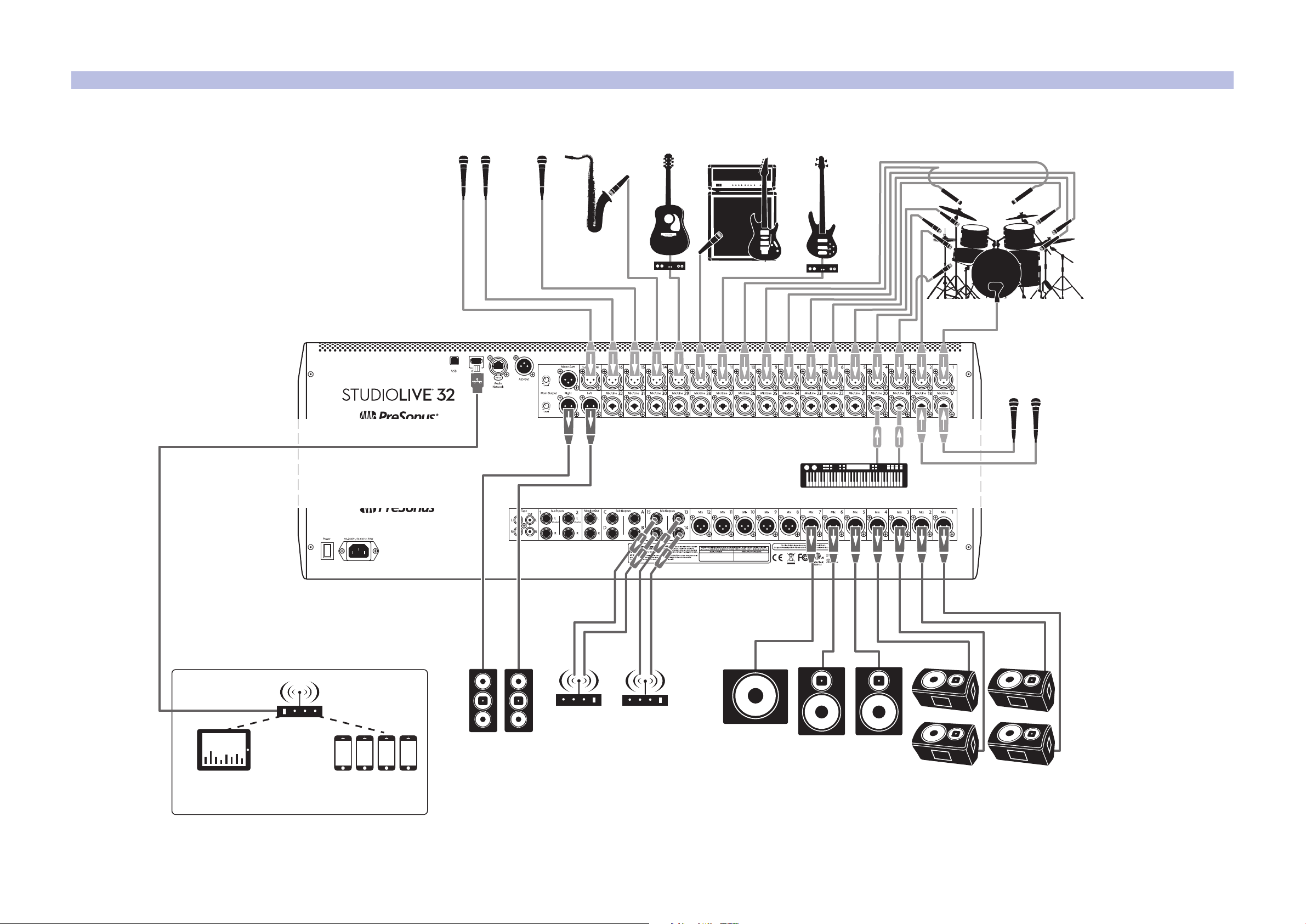
StudioLive control surface
iPad running
UC Surface
Mobile devices
running QMix-UC
wireless router
wireless in-ear
(keys)
wireless in-ear
(lead vocals)
floor wedges
sidefilldrum monitor
acoustic
guitar/DI
sax
keyboard/DI
lead vocal
backup vocal mics
backup vocal mics
drum kit
bass/DIelectric guitar amp
front of house
speakers
subwoofer
3.3 Typical Band Setup Diagrams
3.3 Typical Band Setup Diagrams
StudioLive™ Series III
Owner’s Manual
14
3 Hookup
wireless in-ear
(lead vocals)
wireless in-ear
(keys)
wireless in-ear
(lead guitar)
wireless in-ear
(bass)
floor wedges
StudioLive control surface
iPads running
UC Surface
Mobile devices
running QMix-UC
acoustic
guitar/DI
keyboard/DI
lead and backup
vocal mics
drum kit
bass/DIelectric guitar
amp (lead)
electric guitar
amp (rhythm)
subwoofers
wireless router
piano
podium
mic
wireless
roaming mic
hanging
choir mics
laptop running
Capture
dvd player
cry room
front of house
speakers
3.4 Typical Church Setup Diagrams
3.4 Typical Church Setup Diagrams
StudioLive™ Series III
Owner’s Manual
15

4 Basic Mixing and Routing
4.1 Channel Strip Basics
4 Basic Mixing and Routing
StudioLive™ Series III
Owner’s Manual
StudioLive Series III mixers offer many powerful and flexible mixing tools that allow
you to quickly set up and monitor multiple mixes at once and have been designed to
make managing multiple layers of input channels, mix masters, and fader mixes, as
well as navigating even the most complicated systems simple.
4.1 Channel Strip Basics
If you’ve used a mixer before, the StudioLive channel strip layout may look familiar.
Each channel strip on your StudioLive (apart from the Master) features the following
controls and visual aids:
Scribble Strip Display
This graphical display shows you useful information about the input channel or mix
master that the channel is currently addressing. The following details are displayed:
• Name. Shows the name for the currently displayed channel.
• Number. Shows the number and type of the currently displayed channel.
Standard inputs are numbered normally. Aux input channels begin with “A,” Tape
inputs with “Tape,” FX returns with “FX,” Aux Bus Masters with “Ax,” Subgroup
Masters with “Sb,” and Matrix Masters with “Mx.”
• Pan Position. Shows the current pan position for the currently displayed channel.
Select Button
Press this button to select the current channel or bus. Generally, this function is used
to bring the Fat Channel into focus for the selected input, mix, or bus.
Solo Button
This button will solo its channel to the main outputs or to the monitor outputs,
depending on whether AFL/PFL (Pre-Fader Listening) or SIP (Solo In Place) is selected
in the Solo Edit Menu. Please review Section 9.1 for details.
Mute Button
Press this button to mute the corresponding channel, mix, or bus.
Press it again to unmute.
16
4 Basic Mixing and Routing
4.2 Fader Layers and Banks
Level Meter
Each channel has a three-segment LED level meter, which gives a quick indication of
signal levels flowing through that input, mix, or bus. The bottom segment begins to
light when the signal reaches -40 dBFS. The middle segment begins to light when the
signal reaches -18 dBFS. The top LED, which is red to remind you that clipping is near
or already occurring, begins to light when the signal reaches -1.5 dBFS. It lights most
strongly once the signal reaches -0.2 dBFS (trouble ahead!)
Channel Fader
This touch-sensitive motorized fader lets you control output volume for the input,
mix, or bus that the channel is currently addressing. When the fader is pulled all the
way down (to the ∞ mark), the signal is muted entirely. At the “U” mark (for unity
gain), the mixer is neither boosting nor attenuating the signal. Settings above “U” add
up to 10 dB of gain.
Power User Tip: Because the channel faders are motorized, you can quickly flip between
mixes and recall mix scenes with needing to manually recall them.
StudioLive™ Series III
Owner’s Manual
4.2 Fader Layers and Banks
With so many available analog and digital inputs, mixes, buses, and DCAs, your
StudioLive has more internal mix elements than it does channel strips to control
them. This is where fader layers come in.
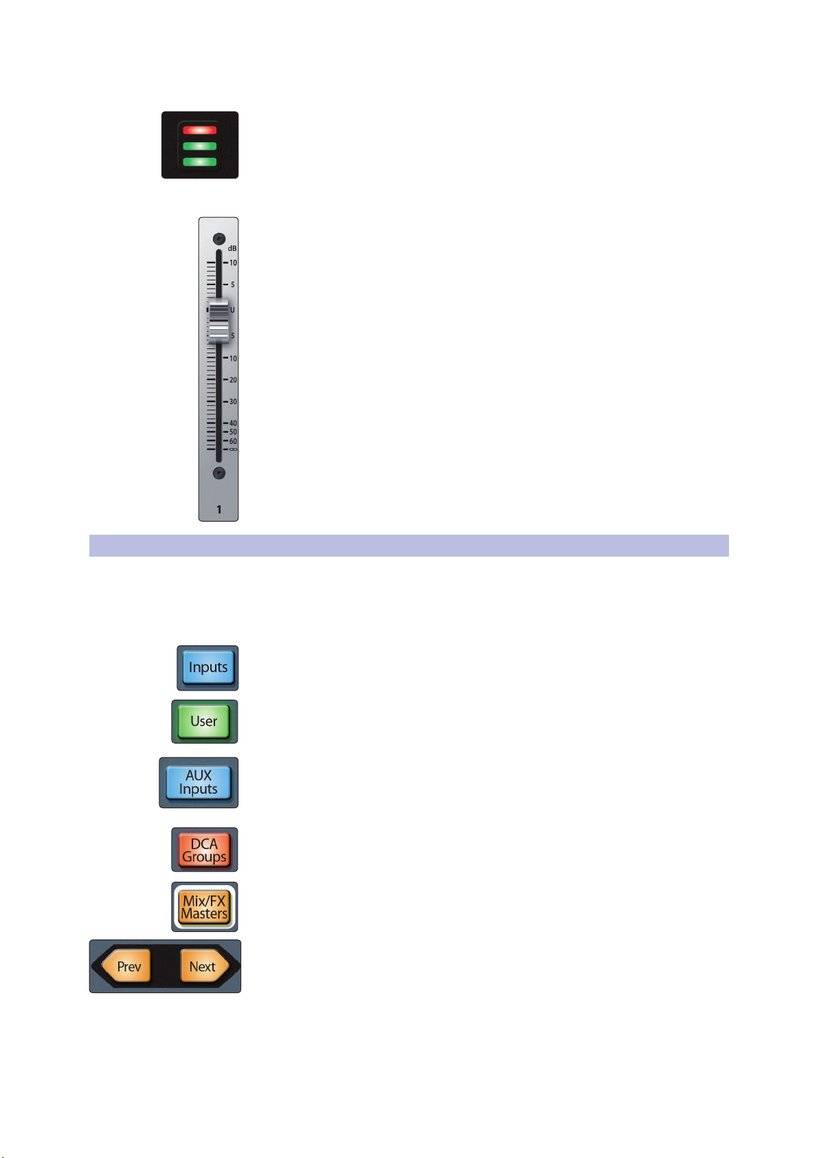
You can switch between these layers using the following buttons:
Inputs. This displays the input channels across all faders so that the channel strips
control corresponding Mic and Mic/Line input channels.
User. The User layer allows you create a custom selection of channels for quicker
access. For more information on the User layer, see Section 4.3.
Aux Inputs (StudioLive 32 and 24 only). While active, the eight channel strips to
the right of the Master fader control FX Returns A-D, Aux Input 1 & 2, Tape Input,
and Talkback. Channel strips 1-24/16 continue to address input channels 1-24/16
as normal.
DCA Groups. Channel strips control the master faders of the Filter DCA Groups. Press
Prev and Next buttons to reach all 24 DCA Groups.
Mix/FX Masters. Channel strips control the master faders and mute/solo states for
available Subgroups, FlexMixes, and FX buses.
Press the Prev and Next buttons to scroll through the other available input channels
and output buses.
17
4 Basic Mixing and Routing
4.3 User Fader Layer
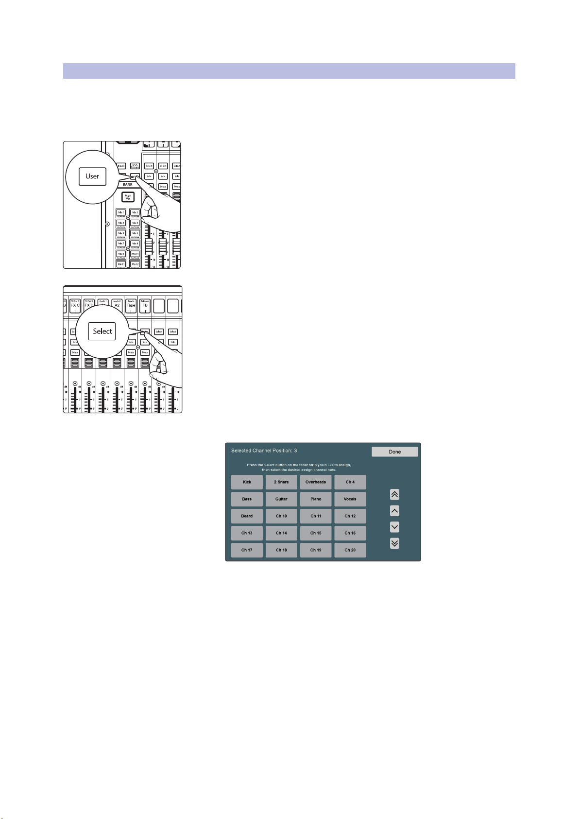
4.3 User Fader Layer
The User layer lets you choose a hand-picked selection of channels that are visible
when you press the User button. This can be useful to access crucial channels quickly,
especially in mixes with high channel counts.
To assign channels to the User layer, do the following.
1. Navigate to the User layer by pressing the User button.
2. Press Select on a channel strip to which you wish to assign a mixer channel
StudioLive™ Series III
Owner’s Manual
or any unused channel in the user layer.
3. The User Layer Assignment screen will be displayed on the touchscreen.
4. Select the channel of your choice on the touchscreen to assign it to the
channel strip of your choice.
5. Repeat steps 2-4 as necessary to populate the User layer with your most
needed channels.
6. Press Done when finished.
To Edit the User layer, press and hold the Select button for the channel whose
assignment you’d like to change. This will open the User Layer Assignment screen.
From here you can unassign the channel completely or change the channel assigned
to it. Every channel, mix master, and DCA group master is available to assign to the
User Layer.
18
4 Basic Mixing and Routing
4.4 Filter DCA Groups
4.4 Filter DCA Groups
Professional mixing consoles have addressed the problem of managing complex
mixes with population groups that reduce the channels you’re viewing at one time
and DCAs that control the overall level of a group of channels.
We’ve combined the best aspects of these solutions with Filter DCAs. A Filter DCA can
contain any combination of the available input channels and effects returns, and you
can create as many Filter DCA groups as you need. You can even include the same
channel in multiple Filter DCAs so you can manage mixes in multiple ways. Each
group is given a master level control so you can control the overall level of the group
while maintaining each channel’s relative balance in the mix. In this way, for example,
you can create a single fader to control every drum in a monitor mix and maintain
the relative level of the drum mix that you created.
Once selected, a Filter DCA group stays active until exited regardless of which mix is
selected. This allows you to adjust the group independently across different mixes.
You can also flip between groups on the fly to change the view of a selected mix.
You can create up to 24 Filter DCA Groups.
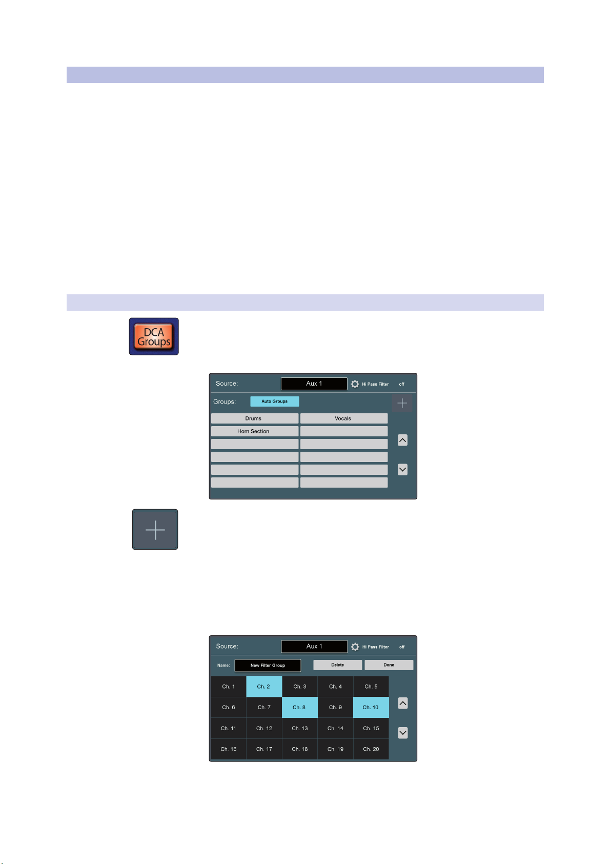
4.4.1 Creating Filter DCAs
1. To create a new Filter DCA Group, press the DCA Groups button in the Master
Control section.
StudioLive™ Series III
Owner’s Manual
2. This will open the Filter DCA Group edit screen.
3. Press the “+” button on the Master Control Touchscreen.
4. Press the default name to create custom filter name. Press “Enter” when done.
5. The Select buttons on your mixer will flash. Press the Select buttons for the
channels you’d like to assign to your new Filter DCA Group. The Select buttons
will illuminate solid as the channel is assigned to the group. You can also use the
select buttons on the Touchscreen to assign channels.
6. Press “Done” when you’ve finished making your channel selections.
19
4 Basic Mixing and Routing
4.5 Main Meters
4.4.2 Editing or Deleting a Filter DCA Group
1. To edit or delete a Filter DCA Group, first touch its name to select it.
2. Touch the Edit button to enter the Filter DCA Group Edit screen.
3. To add or remove a channel from the group, touch the name of the channel in
the provided list to select or deselect them. To name or rename the group, touch
the name field. To delete this group, touch the Delete button.
When you’re finished, touch Done to confirm your changes.
4.4.3 Managing DCA Group Masters
You can bring the master faders for all existing Filter DCA Groups to the channel strips
by pressing the DCA Groups button in the Bank section.
Pressing the Select button on a DCA Group master while the DCA Groups screen is
active will select it on the screen.
Power User Tip: Pressing the Select button for a DCA Group Master will spill the group on
the faders. In this way, you can quickly make adjustments to a DCA mix.
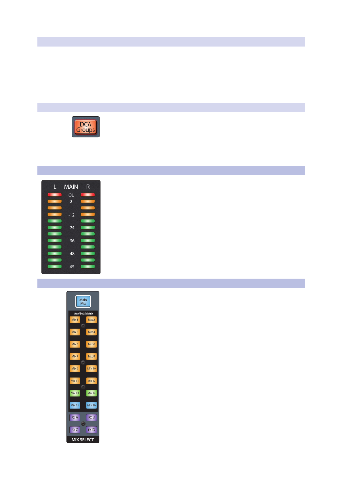
4.5 Main Meters
This meter show signal level for the Main bus. The green LEDs at the bottom begin to
light at -65 dBFS, continuing upward to -18 dBFS. The bottom-most yellow LED
begins to light at -12 dBFS, continuing upward to -2 dBFS. The red LED at the top of
the meter lights when the signal reaches -0.1 dBFS, and remains lit for 5 seconds,
once activated, to better alert you that clipping is occurring.
StudioLive™ Series III
Owner’s Manual
4.6 FlexMixes
StudioLive Series III mixers provide 16 FlexMixes that can be used for a variety
of applications:
• Aux Mixes. Sums Aux Send levels sent from input channels. Aux mixes can be
used for many applications. The two most common applications are creating
monitor mixes and inserting external effects processors into the mix.
• Subgroup. A subgroup allows you to combine multiple channels into a single
bus so that the overall level for the entire group is controlled by a single fader
and processed by the Fat Channel. Subgroups can be routed to main mix, to a
dedicated output, or both.
• Matrix. A variant of the Aux, a Matrix can draw signal from inputs, other mixes,
buses, the main output bus, and so on. Matrix mixes are more commonly used to
send audio to different loudspeaker zones or to provide a producer or director a
different mix.
The Mix Select buttons allow you to choose the mix you’d like to control. When a mix
is selected, the channel faders will display the level for that mix only. These buttons
will change color depending on how they are configured.
20
4 Basic Mixing and Routing
4.6 FlexMixes
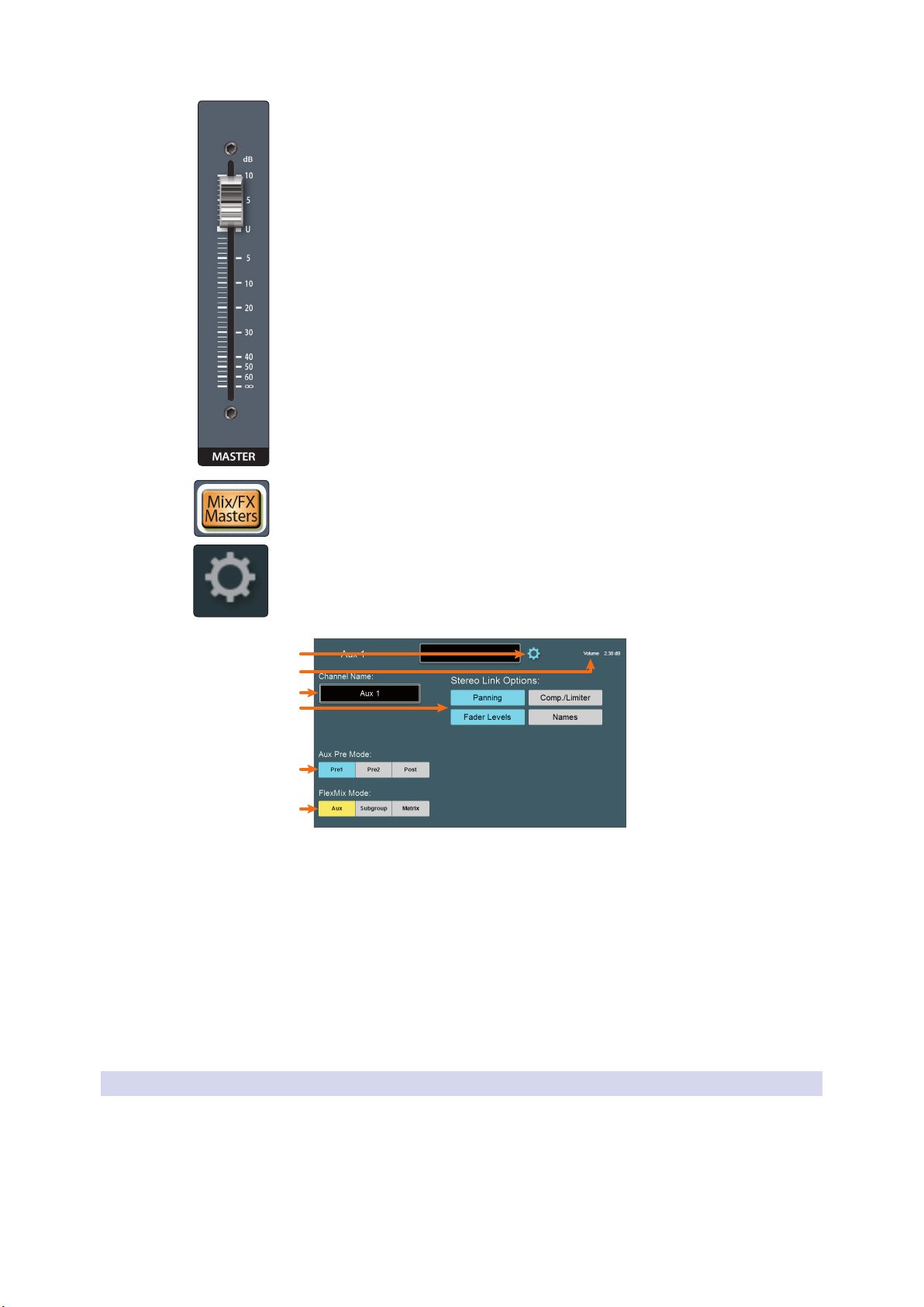
When a mix is selected, the Master fader will control its output level.
To view the master output level for every mix, press the Mix/FX Masters button.
StudioLive™ Series III
Owner’s Manual
To choose the type of FlexMix behavior to be used for the Aux (Aux, Subgroup, or
Matrix), touch the gear-shaped button to open the FlexMix Settings screen and make
your selection from the menu. Once you’re done, exit the FlexMix Settings screen and
create your mix.
1
2
3
4
5
6
1. Close Settings. Tap to exit the Settings menu.
2. Current Parameter. Displays the currently selected parameter and its
current value.
3. Mix Name. Tap to customize name.
4. Stereo Link Options. You can choose to link the four functions when creating a
stereo bus, or leave them independently controllable: Fader Level, Compressor/
Limiter, Names, and Bus Panning (Stereo Matrix Mixing only).
5. Aux Pre Mode (Aux Mode only). Sets the Channel Send position when a
FlexMix is designated as an Aux Mix. See Section 4.6.1 for details.
6. FlexMix Mode. Sets the functionality of the FlexMix: Aux, Subgroup, or Matrix.
4.6.1 Aux Mixes
As its name implies, an Aux mix allows you to create an alternate, or “auxiliary,” mix
that can be routed to an output separate from the Mains. Aux buses have many
applications, the two most common of which are creating monitor mixes and
inserting external effects processors into the mix. When you turn up the aux send
level on a channel, its signal is sent to the corresponding aux output at the level you
choose. In this way, the same channel can be used to create several alternate mixes to
the main mix.
21
4 Basic Mixing and Routing
4.6 FlexMixes
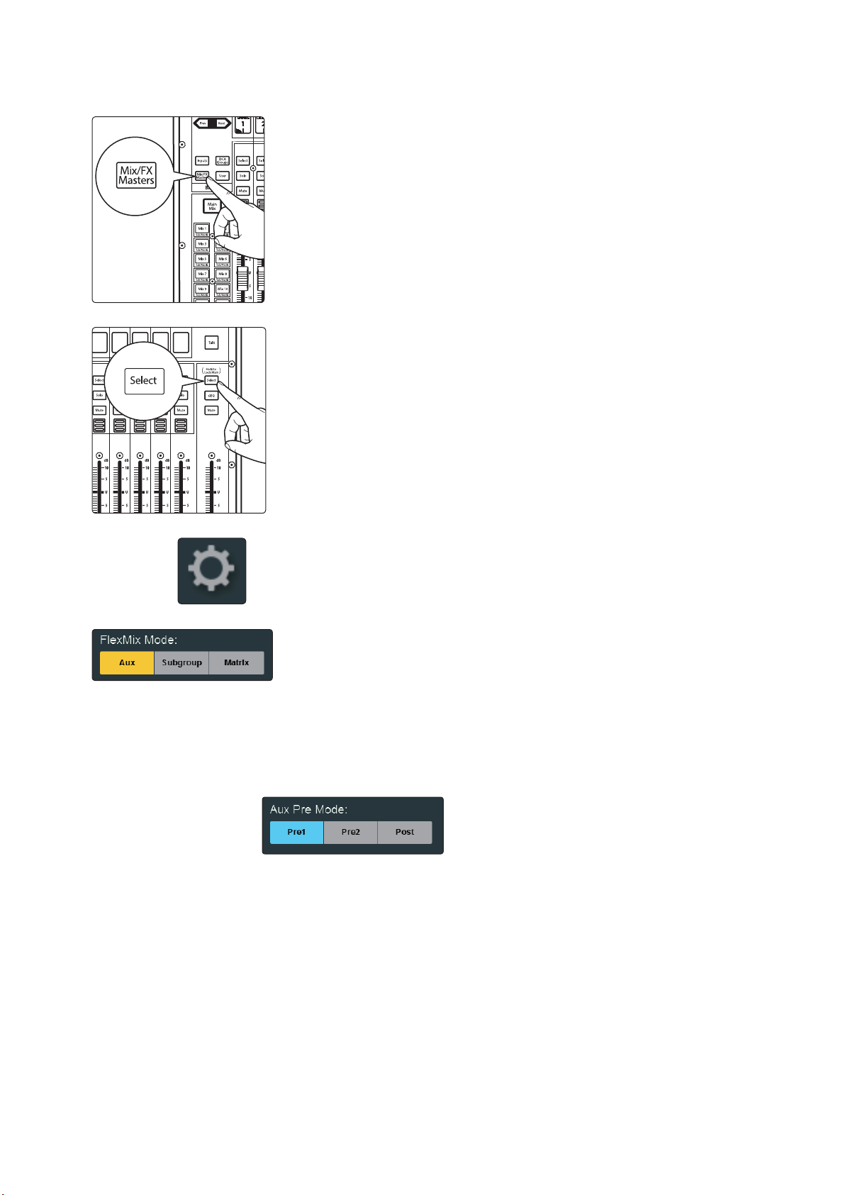
To create an Aux Mix:
1. Press the Mix/FX Master button. This will bring up the FlexMix Masters onto
2. Press the Select button for the FlexMix Master you’d like to make an Aux
StudioLive™ Series III
Owner’s Manual
the channel strips.
Mix.
3. Press the Settings button on the Master Control Touchscreen.
4. Press the Aux button under FlexMix Mode.
Pre/Post Channel Sends
You can select the send positions for the channels routed to each Aux mix. By default,
all aux buses are set to Pre 1. This places the send of every input channel to each aux
bus before the fader, limiter, EQ, and compressor, but after the Polarity Invert switch,
high-pass filter, and gate.
From the FlexMix settings menu, you can choose between three send positions for
your mix:
Pre 1: Sends each channel to the Aux bus after the polarity invert, high-pass filter,
and gate.
Pre 2: Sends each channel to the aux bus after all Fat Channel processing (polarity
invert, high-pass filter, gate, compressor, EQ, and limiter) but before the fader.
Post: Sends each channel to the Aux bus after all Fat Channel processing (polarity
invert, high-pass filter, gate, compressor, EQ, and limiter), and after the fader.
Power User Tip: Use the Pre 2 position for headphone and in-ear mixes to give your
performers a polished “studio” sound. This setting should be avoided for floor wedges, as
compression can cause feedback problems.
22
4 Basic Mixing and Routing
Sub/Matrix Sub/Matrix
Sub/Matrix
Sub/Matrix
Sub/Matrix
Sub/Matrix
Sub/Matrix
Sub/Matrix
Sub/Matrix
Sub/Matrix
Sub/Matrix Sub/Matrix
Sub/Matrix
Sub/Matrix
Sub/Matrix
Sub/Matrix
BANK
Mix 1
Mix 3
Mix 5
Mix 7
Mix 2
Mix 4
Mix 6
Mix 8
Mix 9
Mix 11
Mix 13
Mix 15
Mix 10
Mix 12
Mix 14
Mix 16
Mix 1
4.6 FlexMixes
4.6.1.1 Creating Aux Mixes
Creating custom monitor mixes is critical. If musicians can’t hear themselves or their
bandmates, their performance will suffer. A monitor mix can be mono or stereo. Most
often, an individual live monitor mix is mono and is sent to a floor-wedge or sidefill
monitor (the obvious exception being in-ear monitor systems). A studio monitor mix
is usually stereo because it is sent to a headphone amplifier that requires both a left
and a right-channel input. In both cases, the function of the aux bus is the same.
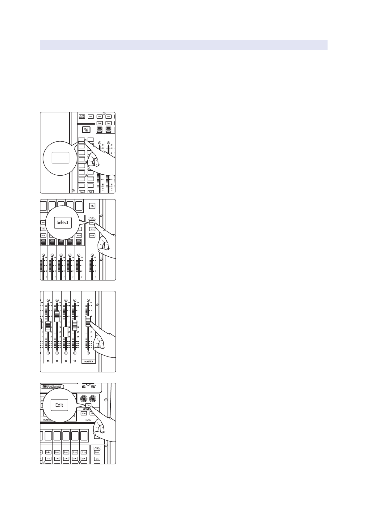
As an example, let’s create a mono monitor mix on FlexMix 1.
1. Press the Mix 1 button in the Mix Select section to access settings for Aux
2. Ask the musician(s) what signals they would like to hear in their monitors,
StudioLive™ Series III
Owner’s Manual
mix 1. The faders move to show send levels to Aux 1 for each channel in
your mix.
and use their requests as a starting point, adjusting the faders for the
relevant channels to create a monitor mix.
3. Press the Flex Fader Select button to access the Fat Channel processing for
the monitor mix output. This can be useful for eliminating feedback in a
monitor. EQ can also be used to increase the presence of an instrument by
boosting that particular frequency range without necessarily boosting the
send level in the mix. This is great for getting the lead guitar to cut through
in the guitarist’s monitor mix and to provide that extra rumble in the
bassist’s mix.
4. Move the Master fader to adjust the overall level of the monitor mix.
5. You can listen to the monitor mix you’re creating in your headphones or
control room monitors by pressing the Edit button in the Monitors control
section.
6. Select Monitor or Phones on the touchscreen, then touch the Aux mix
you’re working on at the moment (Mix 1, in this example).
23
4 Basic Mixing and Routing
4.6 FlexMixes
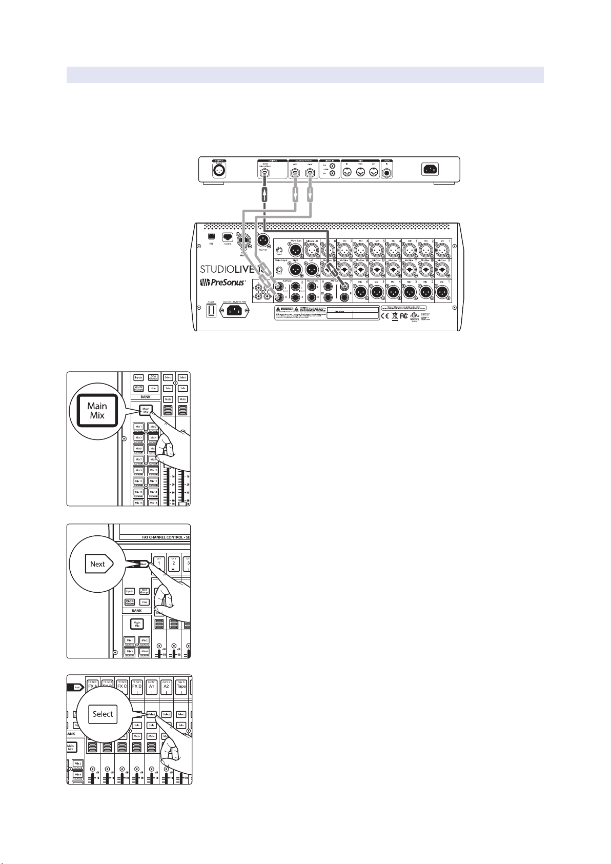
4.6.1.2 Working with External Effects Processors
Creating a mix to send to an external effects processor is similar to creating an
internal FX mix, only in this case, we route the mix signal to a mix output (Mix Output
7, in this example), and route the effected signal from the processor back to a stereo
Aux input (Aux Input 1, in this example) on the mixer. If your effects processor is
mono, connect its output to the L (left) jack of the Aux Input.
StudioLive™ Series III
Owner’s Manual
1. Connect Aux Output 7 to the input of your external effects processor, and
connect the outputs of the processor to the Aux Input 1 jacks.
2. Press the Main Mix button.
3. Press the Next button to bring the Aux Input channel layer.
4. Press the Select button that corresponds to Aux Input 1 (the input pair
you’re using as an effects return), to access its settings in the Fat Channel.
24

4 Basic Mixing and Routing
4.6 FlexMixes
5. Press the Main button in the Fat Channel to assign Aux Input 1 to the main
6. Press the Mix 7 button in the Mix Select section to access settings for Aux 7
7. For each channel that you wish to send to the external processor, move the
8. Move the Master fader to adjust the overall level of the output you’re
9. If you want to send a stereo signal (rather than mono) to your effects
StudioLive™ Series III
Owner’s Manual
output mix.
(the Aux mix you’re using to send channels to the external processor). The
faders move to show send levels to Aux 7 for each channel in your mix.
related fader to the desired level. Setting a fader higher makes the related
channel sound more processed (or “wet”).
sending to the external processor.
processor, connect a pair of Aux outputs, starting with an odd-numbered
output (1 & 2, 3 & 4, or similar) to the inputs of your effects processor and
link the output pair to create a stereo bus.
4.6.2 Subgroups
A subgroup allows you to combine multiple channels into a single bus so that the
overall level for the entire group is controlled by a single fader and can be processed
using the Fat Channel’s noise gate, limiter, compression, and EQ, in addition to the
processing available for each channel. Subgroups can also be soloed and muted.
You will find many uses for subgroups that will make mixing more convenient
and will provide better control of your mix. At the end of this section, we explore
one of the most common ways in which subgroups can help you to create a more
efficient mixing environment and a more successful live mix. But first let’s go over the
subgroup controls.
Note: In addition to providing 16 FlexMixes that can function as subgroups, your
StudioLive also provides four dedicated Subgroups.
To create a Subgroup:
1. Press the Select button for the FlexMix Master you’d like to make a
Subgroup.
2. Press the Settings button on the Master Control Touchscreen.
3. Press the Subgroup button under FlexMix Mode.
25
4 Basic Mixing and Routing
Sub/Matrix Sub/Matrix
Sub/Matrix
Sub/Matrix
Sub/Matrix
Sub/Matrix
Sub/Matrix
Sub/Matrix
Sub/Matrix
Sub/Matrix
Sub/Matrix Sub/Matrix
Sub/Matrix
Sub/Matrix
Sub/Matrix
Sub/Matrix
BANK
Mix 1
Mix 3
Mix 5
Mix 7
Mix 2
Mix 4
Mix 6
Mix 8
Mix 9
Mix 11
Mix 13
Mix 15
Mix 10
Mix 12
Mix 14
Mix 16
Mix 1
4.6 FlexMixes
4.6.2.1 Creating Instrument Subgroups
Grouping individual instruments that create a section in your mix has obvious
advantages: The entire group can be muted or soloed, brought up or down in a mix,
and faded in or out for a more polished intro or outro. Because subgroups can also be
processed by the Fat Channel, some common groups are drums, backing vocals, horn
sections, and string sections. Drums are a classic application for subgroup mixing.
While we’ll use a drum group in this particular example, these principles can be
applied when grouping any type of instrument section.
In this example, our drums will be connected to the StudioLive as follows:
• Channel 1: Kick
• Channel 2: Snare Top
• Channel 3: Snare Bottom
• Channel 4: Floor Tom
• Channel 5: Tom 1
• Channel 6: Tom 2
• Channel 7: Overhead Left
• Channel 8: Overhead Right
• Channel 9: Hi-Hat
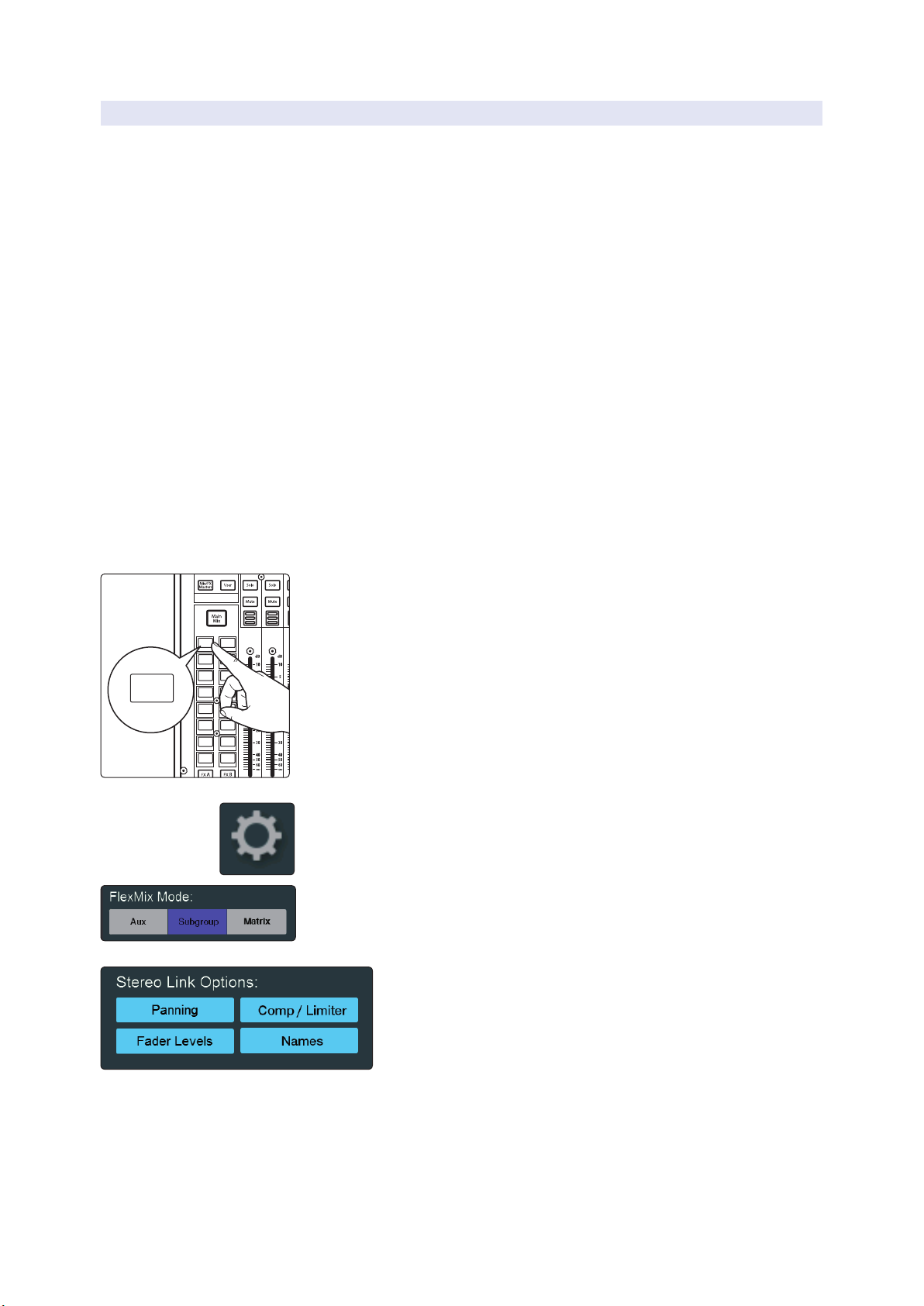
We will create a stereo subgroup by first making both FlexMix 1 and 2 Subgroups and
linking them to create a stereo bus.
1. Press the Mix 1 Select button.
StudioLive™ Series III
Owner’s Manual
2. In the Touch Screen, press the Settings gear.
3. Press the Subgroup button under FlexMix Mode.
4. Enable all four Stereo Link Options.
26
 Loading...