


PM0545007.01
Insert
Additif
Adición
ELECTRIC GENERATOR
GROUPE ELECTROGENE
GENERADOR ELECTRICO
IMPORTANT – Please make certain that persons who are to use this equipment thoroughly read and understand these instructions and any additional instructions provided prior to operation.
IMPORTANT - Prière de vous assurer que les personnes destinées à utiliser cet appareil ont pris soin d'en lire et d'en comprendre le mode d'emploi ou les directives avant de le mettre en marche.
IMPORTANTE. Asegúrese que las personas que utilizarán este equipo lean y entiendan completamente estas instrucciones y cualquier instrucción adicional proporcionada antes del funcionamiento.
www.colemanpowermate.com LFL 06/04 0062595
MAJOR GENERATOR FEATURES |
|
PORTABILITY KIT INSTALLATION |
|
|
|
*10 HP Briggs & Stratton OHV engine
*Low oil sensor
*Receptacles on control panel
*6 gallon plastic fuel tank
*Portability Kit
CONTROL PANEL
A.120 V, 20 Ampere Duplex Receptacle
This duplex is split so that 20 amps of current may be
drawn from each half of the receptacle. However, total power drawn must be kept within nameplate ratings. These receptacles may be used along with the twistlock receptacle provided the generator is not overloaded.
B.120/240 V, 20 Ampere Twistlock Receptacle
A maximum of 20 amps may be drawn from the 120/240
volt receptacle, provided it is the only receptacle used. However, current must be limited to the nameplate rating. If the 120/240 volt receptacle is used along with the 120 volt receptacle, the total load drawn must not exceed the nameplate ratings.
C.Circuit Breakers
The receptacles are protected by an AC circuit breaker. If the generator is overloaded or an external short circuit occurs, the circuit breaker will trip. If this occurs, disconnect all electrical loads and try to determine the cause of the problem before attempting to use the generator again. If overloading causes the circuit breaker to trip, reduce the load. NOTE:
Continuous tripping of the circuit breaker may cause damage to generator or equipment. The circuit breaker may be reset by pushing the button of the breaker.
TOOLS REQUIRED: 1/2” and 9/16" sockets and ratchets, block(s) of wood (minimum of 6” tall).
Refer to the parts list and drawing on pages 8 and 9.
WHEEL INSTALLATION
1.Block up end of generator opposite the fuel tank cap to install wheel kit.
2.Insert wheel spacer (item 43) into the center of the wheel
(item 35).
3.Slide 3/8 x 3.5” bolt (item 41) through the wheel (item 35), then through the wheel bracket on the carrier, with the offset side of the wheel hub against the wheel bracket.
4.Thread 3/8 nyloc nut (item 42) onto the bolt and tighten to securely clamp the wheel assembly to the tubing.
5.Repeat above instructions for the remaining wheel.
FOOT INSTALLATION
1.Blocking up the engine side of the generator, place a spacer (item 38) and a foot (item 37) under the carrier channel. Thread a 5/16-18 x 2.75” bolt (item 36) through the mounting holes and thread a 5/16 washer (item 40) and a 5/16 nyloc nut (item 16) to the bolt to secure the foot to the carrier. Caution: Do not over tighten so that the foot material collapses.
2.Repeat step 1 for the remaining foot.
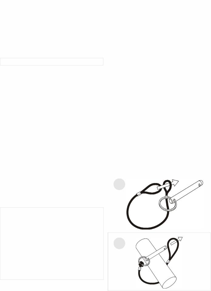
LOCKING HANDLE
1.Attach the lanyards (item 39) to the release pins (item 44) and carrier as shown in the illustration.
2.To lock the handle (item 31) in the extended position, align the holes in the handle brackets with the holes in the carrier brackets and insert the release pins (item 44).
3.Insert caps (item 45) into ends of handle (item 31).
1
2
|
|
English |
|
2 |
|||
|
|

LIMITED WARRANTY (NOT VALID IN MEXICO)
This product is warranted by Coleman Powermate, Inc. to the original retail consumer against defects in material and workmanship for a period of two (2) years from the date of retail purchase and is not transferable. This two year warranty applies only to products used in consumer applications. If this generator is used in a commercial application, then the period of warranty coverage is limited to one (1) year from the date of purchase.
Please complete and return the enclosed Customer Information Card so that we can reach you in the unlikely event a safety recall is needed. Return of this card is not required to validate this warranty.
WHAT IS COVERED: Replacement parts and labor.
WHAT IS NOT COVERED: Transportation charges to Coleman Powermate, Inc. for defective products. Transportation charges to consumer for repaired products. Brushes, fuses, rubber feet, and receptacles. Damages caused by abuse, accident, improper repair, or failure to perform normal maintenance. Power units or engines which are covered exclusively by the warranties of their manufacturer. Sales outside of the United States or Canada. Any other expense including consequential damages, incidental damages, or incidental expenses, including damage to property. Some states do not allow the exclusion or limitation of incidental or consequential damages, so the above limitation or exclusion may not apply to you.
IMPLIED WARRANTIES: Any implied warranties, including the Implied Warranties of Merchantability and Fitness For A Particular Purpose, are limited in duration to one (1) year from the date of retail purchase. Some states do not allow limitations on how long an implied warranty lasts, so the above limitation may not apply to you.
HOW TO OBTAIN WARRANTY PERFORMANCE:
Replacement parts and service are available from Coleman Powermate, Inc. Service Centers. Locate your nearest Service Center by calling TOLL FREE 1-800-445-1805. In the unlikely event a Service Center can not be located you may call Coleman Powermate, Inc. for a return authorization number.
Any unit returned WITHOUT an authorization number will be refused.
To the extent any provision of this warranty is prohibited by federal, state, or municipal law, and cannot be preempted, it shall not be applicable. This warranty gives you specific rights, and you may also have other rights which vary from state to state.
|
|
|
English |
3 |
|
|
|
|
CARACTÉRISTIQUES PRINCIPALES DU
GROUPE ELECTROGENE
*Moteur 10 HP Briggs & Stratton OHV
*Détecteur de bas niveau d'huile
*Prises sur tableau de commande
*Réservoir de carburant en plastique d'une contenance de 22.7 litres (6 gallons)
*Kit de transport
TABLEAU DE COMMANDE
A.Prise double de 120 V, 20 A
Cette prise double est câblée pour fournir 20 A. La charge totale doit cependant rester dans les limites indiquées sur la plaque signalétique. Ces prises peuvent s’utiliser en conjonction avec la prise à verrouillage à condition que le générateur ne soit pas surchargée.
B.Prise à verrouillage de 120/240 V, 20 A
Cette prise de 120/240 V fournit un maximum de 20 A à condition que ce soit la seule utilisée. La charge totale doit par ailleurs rester dans les limites indiquées sur la plaque signalétique. Si la prise de 120/240 V est utilisée en conjonction avec les prises de 120 V, la charge totale ne doit pas dépasser les limites indiquées sur la plaque.
C.Disjoncteurs
Les prises sont protégées par un disjoncteur alternatif. En
cas de surcharge ou de court-circuit extérieur, le disjoncteur saute. Si cela se produit, débrancher tout appareil relié au groupe électrogène et essayer de déterminer la cause du problème avant d’essayer de le réutiliser. Si le disjoncteur saute en raison d’une surcharge, réduire la charge.
REMARQUE : Le groupe électrogène ou les appareils branchés dessus peuvent se trouver abîmés si le disjoncteur saute continuellement. Appuyer sur le bouton du disjoncteur pour le réenclencher.
L'INSTALLATION DE KIT DE
TRANSPORT
OUTILS NÉCESSAIRES : Cliquet à rochet de 1/2 po et 9/16 po, blocs de bois (minimum de 6 po (15,2 cm) de hauteur)
Reportez-vous à la liste des pièces et au dessin des pages 8 et 9.
INSTALLATION DES ROUES
1.Faire reposer l’extrémité de la génératrice à l’opposé de celle où se trouve le capuchon du réservoir d’essence sur un bloc de façon à pouvoir effectuer la pose de la roue.
2.Insérer une bague d’espacement (article 43) dans le centre de la roue (article 35).
3.Enfiler le boulon de 3/8 x 3.5 po (article 41) dans la roue (article 35), puis dans le support de la roue sur le transporteur, en le plaçant de façon à ce que le côté le plus en creux du moyeu de la roue repose contre le support.
4.Enfiler l’écrou à frein élastique de 3/8 po (article 42) sur le boulon et serrer de façon à bien fixer la roue sur la transporteur.
5.Procéder de la même façon pour l’autre roue.
INSTALLATION DU PIED
1.En bloquant le côté moteur de la génératrice, mettre en place le entretoise (article 38) et un pied (article 37) sous le profilé en U. Visser un boulon de 5/16-18 x 2.75 po (article 36) dans les trous de fixation, puis visser sur le boulon un écrou nyloc de 5/16 po (article 16), avec une rondelle de 5/16 po (article 40) pour fixer le pied au profilé.
Attention: ne pas trop serrer, pour ne pas écraser le matériau du pied.
2.Répéter l'étape 1 pour le pied restant.
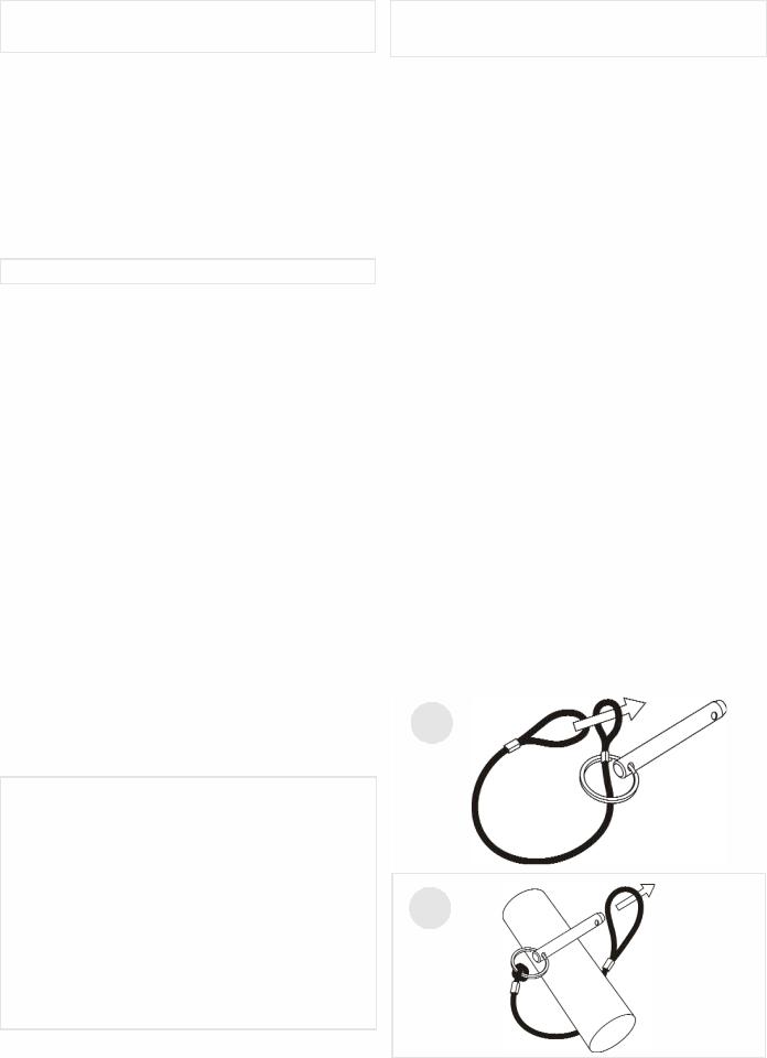
POIGNEE VERROUILLANT
1.Attacher le lanyards (article 39) aux épingles de relâchement (article 44) et le transporteur selon l'illustration.
2.Pour verrouiller la poignée (article 31) dans la position étendue, aligner les trous dans les support de poignée avec les trous dans les support de transporteur et insérer les épingles de relâchement (article 44).
3.L'insertion capuchon (article 45) dans les fins de poignée
(article 31).
1
2
|
|
|
4 |
French |
|
|
|
|
 Loading...