


Operator Manual |
• |
Manuel de l’opérateur • Manual del operador |
ELECTRIC GENERATOR • GROUPE ELECTROGENE • GENERADOR ELECTRICO
PM0106507
IMPORTANT – Please make certain that persons who are to use this equipment thoroughly read and understand these instructions and any additional instructions provided prior to operation.
IMPORTANT - Prière de vous assurer que les personnes destinées à utiliser cet appareil ont pris soin d'en lire et d'en comprendre le mode d'emploi ou les directives avant de le mettre en marche.
IMPORTANTE - Asegúrese que las personas que utilizarán este equipo lean y entiendan completamente estas instrucciones y cualquier instrucción adicional proporcionada antes del funcionamiento.
|
Record the serial number as |
Enregistrer le numéro de série |
Registre de serie como se indica |
|||||
|
indicated on your Generator’s |
figurant sur la plaque signalétique |
|
en la placa del nombre de su |
||||
|
|
nameplate: |
|
|
du groupe électrogène: |
|
|
generador: |
Serial No.______________________ |
Nº de série ____________________ |
No. de serie ___________________ |
||||||
|
|
|
|
|
|
|
|
|
|
|
|
|
|
|
|
|
|
STOP |
DO NOT RETURN TO |
ARRÊT |
NE PAS RETOURNER |
ALTO |
NO LO DEVUELVA A |
STORE! |
AU MAGASIN! |
LA TIENDA! |
|||
|
CALL US FIRST! |
APPELEZ–NOUS D’ABORD! |
|
¡PRIMERO LLÁMENOS! |
|
|
CUSTOMER HOTLINE |
|
ASSISTANCE |
|
LÍNEA DIRECTA DE |
|
1-800-445-1805 |
|
TELEPHONIQUE |
ATENCIÓN AL CLIENTE |
|
|
|
|
A LA CLIENTELE |
|
1-800-445-1805 |
FOR QUESTIONS OR |
|
1-800-445-1805 |
|
|
|
SERVICE INFORMATION |
POUR L'INFORMATION DE |
PARA la INFORMACION de |
|||
|
|
PREGUNTAS O SERVICIO |
|||
|
|
QUESTIONS OU SERVICE |
|
|
|
www.powermate.com |
02/11 0068209 |

TABLE OF CONTENTS
Safety and operation rules . . . . . . . . . . . . . . . . . . . . . . . . . . . . . . . . . 3
Spark arresting muffler . . . . . . . . . . . . . . . . . . . . . . . . . . . . . . . . . . . . 4
Determining total wattage . . . . . . . . . . . . . . . . . . . . . . . . . . . . . . . . . . 4
Operating voltage . . . . . . . . . . . . . . . . . . . . . . . . . . . . . . . . . . . . . . . . 5 Installation. . . . . . . . . . . . . . . . . . . . . . . . . . . . . . . . . . . . . . . . . . . . . . 5
Before operation . . . . . . . . . . . . . . . . . . . . . . . . . . . . . . . . . . . . . . . . . 6
Ground fault circuit interrupter (GFCI) . . . . . . . . . . . . . . . . . . . . 6
Grounding the generator. . . . . . . . . . . . . . . . . . . . . . . . . . . . . . . 6
Lubrication . . . . . . . . . . . . . . . . . . . . . . . . . . . . . . . . . . . . . . . . . 6 Low oil sensor. . . . . . . . . . . . . . . . . . . . . . . . . . . . . . . . . . . . . . . 6
Fuel . . . . . . . . . . . . . . . . . . . . . . . . . . . . . . . . . . . . . . . . . . . . . . . 6
Generator features . . . . . . . . . . . . . . . . . . . . . . . . . . . . . . . . . . . . . . . 7
DC usage . . . . . . . . . . . . . . . . . . . . . . . . . . . . . . . . . . . . . . . . . . . . . . 8
Portability kit installation . . . . . . . . . . . . . . . . . . . . . . . . . . . . . . . . . . . 9 Electric Start . . . . . . . . . . . . . . . . . . . . . . . . . . . . . . . . . . . . . . . . . . . 10
Starting the unit . . . . . . . . . . . . . . . . . . . . . . . . . . . . . . . . . . . . . . . . . 11
Pre-start preparation . . . . . . . . . . . . . . . . . . . . . . . . . . . . . . . . . 11
Starting the engine . . . . . . . . . . . . . . . . . . . . . . . . . . . . . . . . . . 11
Applying load. . . . . . . . . . . . . . . . . . . . . . . . . . . . . . . . . . . . . . . 11 Shutting the generator off . . . . . . . . . . . . . . . . . . . . . . . . . . . . . 11
Periodic Maintenance . . . . . . . . . . . . . . . . . . . . . . . . . . . . . . . . . . . . 12
Maintenance . . . . . . . . . . . . . . . . . . . . . . . . . . . . . . . . . . . . . . . . . . . 12
Spark plug. . . . . . . . . . . . . . . . . . . . . . . . . . . . . . . . . . . . . . . . . 12
Oil type . . . . . . . . . . . . . . . . . . . . . . . . . . . . . . . . . . . . . . . . . . . 12
Oil replacement. . . . . . . . . . . . . . . . . . . . . . . . . . . . . . . . . . . . . 12
Air filter cleaning . . . . . . . . . . . . . . . . . . . . . . . . . . . . . . . . . . . . 12 Fuel valve filter cleaning . . . . . . . . . . . . . . . . . . . . . . . . . . . . . . 12
Fuel strainer cleaning . . . . . . . . . . . . . . . . . . . . . . . . . . . . . . . . 12
Brushes. . . . . . . . . . . . . . . . . . . . . . . . . . . . . . . . . . . . . . . . . . . 13
Inspecting the brushes . . . . . . . . . . . . . . . . . . . . . . . . . . . . . . . 13
Heat shield . . . . . . . . . . . . . . . . . . . . . . . . . . . . . . . . . . . . . . . . 13 Engine carburetor icing. . . . . . . . . . . . . . . . . . . . . . . . . . . . . . . 13
Quick starting tips . . . . . . . . . . . . . . . . . . . . . . . . . . . . . . . . . . . 13
Service and storage . . . . . . . . . . . . . . . . . . . . . . . . . . . . . . . . . . . . . 13
Infrequent service . . . . . . . . . . . . . . . . . . . . . . . . . . . . . . . . . . . 13
Long term storage. . . . . . . . . . . . . . . . . . . . . . . . . . . . . . . . . . . 13 Engine troubleshooting . . . . . . . . . . . . . . . . . . . . . . . . . . . . . . . . . . . 14
Engine specifications . . . . . . . . . . . . . . . . . . . . . . . . . . . . . . . . . . . . 14
Service information . . . . . . . . . . . . . . . . . . . . . . . . . . . . . . . . . . . . . . 15
Limited warranty . . . . . . . . . . . . . . . . . . . . . . . . . . . . . . . . . . . . . . . . 15
Parts drawings and parts list . . . . . . . . . . . . . . . . . . . . . . . . . . . . 42-45 Emission control warranty. . . . . . . . . . . . . . . . . . . . . . . . . . . . . . . . . 46
TABLE DES MATIERES
Régles d’opération et de sécurité . . . . . . . . . . . . . . . . . . . . . . . . . . . 16 Silencieux pare-étincelles . . . . . . . . . . . . . . . . . . . . . . . . . . . . . . . . . 17 Determination de la puissance totale nécessaire . . . . . . . . . . . . . . . 17
Vérifier la tension . . . . . . . . . . . . . . . . . . . . . . . . . . . . . . . . . . . . . . . 18
Installation. . . . . . . . . . . . . . . . . . . . . . . . . . . . . . . . . . . . . . . . . . . . . 18 Avant de mettre en marche . . . . . . . . . . . . . . . . . . . . . . . . . . . . . . . 19 Protection avec disjoncteur différentiel (GFCI) . . . . . . . . . . . . . 19 Mise en place de l'appareil. . . . . . . . . . . . . . . . . . . . . . . . . . . . . 19
Lubrification . . . . . . . . . . . . . . . . . . . . . . . . . . . . . . . . . . . . . . . . 19
Le détecteur de bas niveau d'huile . . . . . . . . . . . . . . . . . . . . . . 19 Carburant . . . . . . . . . . . . . . . . . . . . . . . . . . . . . . . . . . . . . . . . . . 19 Caractéristiques du groupe electrogene. . . . . . . . . . . . . . . . . . . . . . 20 Utilisation de courant continu (c.c.) . . . . . . . . . . . . . . . . . . . . . . . . . 21
L’installation de kit de transport . . . . . . . . . . . . . . . . . . . . . . . . . . . . 22
Démarrage électrique . . . . . . . . . . . . . . . . . . . . . . . . . . . . . . . . . . . . 23 Démarrage de l'appareil . . . . . . . . . . . . . . . . . . . . . . . . . . . . . . . . . . 24 Préparatifs au démarrage. . . . . . . . . . . . . . . . . . . . . . . . . . . . . . 24 Démarrage du moteur . . . . . . . . . . . . . . . . . . . . . . . . . . . . . . . . 24
Branchement des appareils . . . . . . . . . . . . . . . . . . . . . . . . . . . . 24
Arrêt de l'appareil . . . . . . . . . . . . . . . . . . . . . . . . . . . . . . . . . . . . 24 Entretien périodique . . . . . . . . . . . . . . . . . . . . . . . . . . . . . . . . . . . . . 25 Entretien . . . . . . . . . . . . . . . . . . . . . . . . . . . . . . . . . . . . . . . . . . . . . . 25
La bougie d’allumage . . . . . . . . . . . . . . . . . . . . . . . . . . . . . . . . 25 Le type d’huile. . . . . . . . . . . . . . . . . . . . . . . . . . . . . . . . . . . . . . 25 Remplacement d’huile . . . . . . . . . . . . . . . . . . . . . . . . . . . . . . . 25 Nettoyage du filtre à air . . . . . . . . . . . . . . . . . . . . . . . . . . . . . . 25
Nettoyage du filtre du robinet à essence . . . . . . . . . . . . . . . . . 25
Nettoyage de la crépine du réservoir à carburant . . . . . . . . . . 25 Les balais . . . . . . . . . . . . . . . . . . . . . . . . . . . . . . . . . . . . . . . . . 26 Inspection des balais . . . . . . . . . . . . . . . . . . . . . . . . . . . . . . . . 26 Écrans de chaleur. . . . . . . . . . . . . . . . . . . . . . . . . . . . . . . . . . . 26
Givrage du carburateur. . . . . . . . . . . . . . . . . . . . . . . . . . . . . . . 26
Trucs de démarrage rapide . . . . . . . . . . . . . . . . . . . . . . . . . . . 26 Usage et entreposage . . . . . . . . . . . . . . . . . . . . . . . . . . . . . . . . . . . 26 Usage peu fréquent . . . . . . . . . . . . . . . . . . . . . . . . . . . . . . . . . 26 Entreposage à long terme . . . . . . . . . . . . . . . . . . . . . . . . . . . . 26
Depannage du moteur . . . . . . . . . . . . . . . . . . . . . . . . . . . . . . . . . . . 27
Caracteristiques du moteur. . . . . . . . . . . . . . . . . . . . . . . . . . . . . . . . 27 Service clientèle . . . . . . . . . . . . . . . . . . . . . . . . . . . . . . . . . . . . . . . . 28 Garantie limitée. . . . . . . . . . . . . . . . . . . . . . . . . . . . . . . . . . . . . . . . . 28 Schema des pièces et liste des pièces . . . . . . . . . . . . . . . . . . . . 42-45
INDICE
Reglas de seguridad y de funcionamiento . . . . . . . . . . . . . . . . . . . . 29
Silenciador apagachispas . . . . . . . . . . . . . . . . . . . . . . . . . . . . . . . . . 30
Como determinar el vataje total . . . . . . . . . . . . . . . . . . . . . . . . . . . . 30
Requerimiento de voltaje . . . . . . . . . . . . . . . . . . . . . . . . . . . . . . . . . 31 Instalacion. . . . . . . . . . . . . . . . . . . . . . . . . . . . . . . . . . . . . . . . . . . . . 31
Antes de la operacion . . . . . . . . . . . . . . . . . . . . . . . . . . . . . . . . . . . . 32
Protección de interruptor de circuito de falla de
conexión a tierra (GFCI, por sus siglas en inglés). . . . . . . . . . . 32
Puesta a tierra del generador. . . . . . . . . . . . . . . . . . . . . . . . . . . 32 Lubricacion . . . . . . . . . . . . . . . . . . . . . . . . . . . . . . . . . . . . . . . . . 32
El sensor del nivel bajo de aceite . . . . . . . . . . . . . . . . . . . . . . . 32
Combustible . . . . . . . . . . . . . . . . . . . . . . . . . . . . . . . . . . . . . . . . 32
Caracteristicas del generador. . . . . . . . . . . . . . . . . . . . . . . . . . . . . . 33
Uso de DC . . . . . . . . . . . . . . . . . . . . . . . . . . . . . . . . . . . . . . . . . . . . 34
Instalacion del juego de transport. . . . . . . . . . . . . . . . . . . . . . . . . . . 35 Arranque eléctrico. . . . . . . . . . . . . . . . . . . . . . . . . . . . . . . . . . . . . . . 36
Arranque de la unidad . . . . . . . . . . . . . . . . . . . . . . . . . . . . . . . . . . . 37
Preparacion antes de arrancar. . . . . . . . . . . . . . . . . . . . . . . . . . 37 Arranque del motor. . . . . . . . . . . . . . . . . . . . . . . . . . . . . . . . . . . 37 Como aplicar una carga . . . . . . . . . . . . . . . . . . . . . . . . . . . . . . 37
Apagado del generador . . . . . . . . . . . . . . . . . . . . . . . . . . . . . . . 37
Mantenimiento periódico. . . . . . . . . . . . . . . . . . . . . . . . . . . . . . . . . . 38
Mantenimiento . . . . . . . . . . . . . . . . . . . . . . . . . . . . . . . . . . . . . . . . . 38
Bujia . . . . . . . . . . . . . . . . . . . . . . . . . . . . . . . . . . . . . . . . . . . . . 38
Tipo de aceite . . . . . . . . . . . . . . . . . . . . . . . . . . . . . . . . . . . . . . 38
Cambio del aceite . . . . . . . . . . . . . . . . . . . . . . . . . . . . . . . . . . . 38
Cómo limpiar el filtro de aire. . . . . . . . . . . . . . . . . . . . . . . . . . . 38 Cómo limpiar el filtro de la vàlvula de combustible . . . . . . . . . 38
Limpieza del filtro de combustible . . . . . . . . . . . . . . . . . . . . . . 38
Escobillas . . . . . . . . . . . . . . . . . . . . . . . . . . . . . . . . . . . . . . . . . 39
Revisión de las escobillas . . . . . . . . . . . . . . . . . . . . . . . . . . . . 39
Escudo contra el calor . . . . . . . . . . . . . . . . . . . . . . . . . . . . . . . 39 Congelamiento del carburador del motor . . . . . . . . . . . . . . . . . 39
Instrucciones rápidas para el arranque . . . . . . . . . . . . . . . . . . 39
Servicio y almacenamiento. . . . . . . . . . . . . . . . . . . . . . . . . . . . . . . . 39
Servicio poco frecuente . . . . . . . . . . . . . . . . . . . . . . . . . . . . . . 39 Almacenamiento a largo plazo . . . . . . . . . . . . . . . . . . . . . . . . . 39 Deteccion de fallos del motor . . . . . . . . . . . . . . . . . . . . . . . . . . . . . . 40 Especificaciones del motor . . . . . . . . . . . . . . . . . . . . . . . . . . . . . . . . 40
Informacion de servicio al cliente . . . . . . . . . . . . . . . . . . . . . . . . . . . 41
Garantia limitada. . . . . . . . . . . . . . . . . . . . . . . . . . . . . . . . . . . . . . . . 41 Diagrama de piezas y lista de piezas . . . . . . . . . . . . . . . . . . . . . 42-45
2 |
Customer Hotline 1-800-445-1805 |

SAFETY INFORMATION
DANGER indicates a potentially hazardous situation which, if not avoided, WILL result in death or serious injury.
WARNING indicates a potentially hazardous situation which, if not avoided, could result in death or serious injury.
CAUTION indicates a potentially hazardous situation which, if not avoided, may result in minor or moderate personal injury, or property damage.
SAFETY AND OPERATION RULES
WARNING - Failure to follow these instructions and warnings may result in death, personal injury, or property damage.
1.Read carefully and understand operator manual prior to operation of this product. Follow all warnings and instructions.
2.Know your equipment. Consider the applications, limitations, and the potential hazards specific to your unit.
3.Equipment must be placed on a firm, supporting surface.
4.Load must be kept within rating stated on generator nameplate. Overloading will damage the unit or shorten its life.
5.Engine must not be run at excessive speeds. Operating an engine at excessive speeds increases the hazard of personal injury.
Do not tamper with parts which may increase or decrease the governed speed.
6.To prevent accidental starting, always remove the spark plug or cable from the spark plug before maintaining the generator or engine.
7.Units with broken or missing parts, or without protective housing or covers, should never be operated. Contact your service center for replacement parts.
8.Units should not be operated or stored in wet or damp conditions or on highly conductive locations such as metal decking and steel work.
9.Keep the generator clean and free of oil, mud and other foreign matter.
10.Extension cords, power cords, and all electrical equipment must be in good condition. Never operate electrical equipment with damaged or defective cords.
11.Store the generator in a well ventilated area with the fuel tank empty. Fuel should not be stored near the generator.
12.Your generator should never be operated under these conditions:
a.Uncontrolled change in engine speed.
b.Electrical output loss.
c.Overheating in connected equipment.
d.Sparking.
e.Damaged receptacles.
f.Engine misfire.
g.Excessive vibration.
h.Flame or smoke.
i.Enclosed compartment.
j.Rain, snow or inclement weather. Do not let the unit get wet when operating.
13.Check the fuel system periodically for leaks or signs of deterioration such as chafed or spongy hose, loose or missing clamps, or damaged tank or cap. All defects should be corrected before operation.
14.The generator should be operated, serviced, and refueled only under the following conditions:
a.Start and run the generator outdoors. Do not run the generator in an enclosed area, even if doors or windows are open; avoid areas where vapors may be trapped, such as pits, garages, cellars, excavations and boat bilges. DANGER - CARBON MONOXIDE HAZARD: The engine exhaust contains carbon monoxide, a poisonous, odorless, invisible gas which, if breathed, may cause death or serious personal injury. If you start to feel sick, dizzy or weak while using the generator, shut it off and get to fresh air right away; you may have carbon monoxide poisoning.
b.Good ventilation for cooling. Air flow and temperatures are important for air cooled units. Temperatures should not exceed 104º F ambient (40º C).
c.Refuel the generator in a well lighted area. Avoid fuel spills and never refuel while the generator is running. Allow engine to cool for two minutes prior to refueling.
English |
3 |
Customer Hotline 1-800-445-1805 |
d.Do not refuel near open flames, pilot lights, or sparking electrical equipment such as power tools, welders, and grinders.
e.The muffler and air cleaner must be installed and in good condition at all times as they function as flame arresters if backfiring occurs.
f.Do not smoke near the generator.
15.Ensure that generator is properly grounded. (See “Grounding the generator” section in this
manual.)
16.Do not wear loose clothing, jewelry, or anything that may be caught in the starter or other rotating parts.
17.Unit must reach operating speed before electrical loads are connected. Disconnect loads before turning off engine.
18.To prevent surging that may possibly damage equipment, do not allow engine to run out of fuel when electrical loads are applied.
19.When powering solid state equipment, a Power Line Conditioner should be used to avoid possible damage to equipment.
20.Do not stick anything through ventilating slots, even when the generator is not operating. This can damage the generator or cause personal injury.
21.Before transporting the generator in a vehicle, drain all fuel to prevent leakage that may occur.
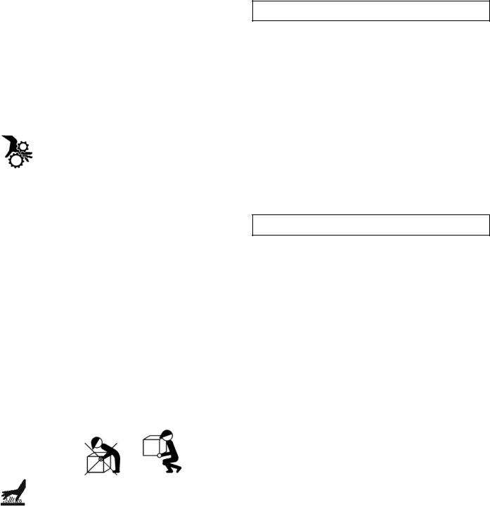
22.Use proper lifting techniques when transporting the generator from site to site. Improper lifting techniques may result in personal injury.
23.To avoid burns, do not touch engine muffler or other engine or generator surfaces which became hot during operation.
SPARK ARRESTER
YOUR PRODUCT MAY NOT BE EQUIPPED WITH A SPARK ARRESTING MUFFLER. If the product will be used around flammable materials, such as agricultural crops, forests, brush, grass, or other similar items, then an approved spark arrester should be installed and is legally required in the State of California. The California statutes requiring a spark arrester are Sections 13005(b), 4442 and 4443. Spark Arresters are also required on some U.S. Forest Service land and may also be legally required under other statutes and ordinances. An approved spark arrester is available from our product dealers, or may be ordered from Pramac America, LLC, P.O. Box 6001, Kearney, Nebraska 68847. 1-800-445-1805.
DETERMINING TOTAL WATTAGE
In order to prevent overloading and possible damage to your generator it is necessary to know the total wattage of the connected load. To determine which tools and/or appliances your generator will run follow these steps:
1.Determine if you want to run one item or multiple items simultaneously.
2.Check wattage requirements for the items you will be running by referring to the load’s nameplate or by calculating it (multiply amps x volts = watts).
3.Total the watts for each item. If the nameplate only gives volts and amps, multiply volts x amps = watts.
1 KW = 1,000 watts.
4.Motorized appliances or tools require more than their rated wattage for start up.
NOTE: Allow 2 1/2 to 4 times the listed wattage for starting equipment powered by electric motors.
5.The generator’s rated watts should match or exceed the total number of watts required for the equipment you want to run.
6.Always connect the heaviest load to the generator first, then add other items one at a time.
English |
4 |
Customer Hotline 1-800-445-1805 |
OPERATING VOLTAGE
CAUTION: Operating voltage and frequency requirement of all electronic equipment should be checked prior to plugging them into this generator. Damage may result if the equipment is not designed to operate within a +/- 10% voltage variation, and +/- 3 hz frequency variation from the generator name plate ratings. To avoid damage, always have an additional load plugged into the generator if solid state equipment (such as a television set) is used. A power line conditioner is recommended for some solid state applications.
A power line conditioner should be used when running one or more of the following solid state items:
Garage door openers
Kitchen appliances with digital displays
Televisions
Stereos
Personal computers
Quartz clocks
Copy machines
Telephone equipment
Other solid state equipment may require a power line conditioner. For more information, contact our Customer Service Department at 1-800-445-1805.
INSTALLATION
To avoid possible personal injury or equipment damage, a registered electrician or an authorized service representative should perform installation and all service. Under no circumstances should an unqualified person attempt to wire into a utility circuit.
To avoid backfeeding into utility systems, isolation of the residence electrical system is required.
Before temporary connection of the generator to the residence electrical system, turn off the main service/disconnect.
If your generator is to be used as a stand-by power source in case of utility power failure, it should be installed by a registered electrician and in compliance with all applicable local electrical codes.
Proper use requires that a double throw transfer switch be installed by a licensed qualified electrician so that the building's electrical circuits may be safely switched between utility power and the generator's output, thereby preventing backfeed into the power utility's electrical system.
To avoid backfeeding into utility systems, isolation of the residence electrical system is required. Before temporary connection of a generator to the residence electrical system turn off the main switch. Before making permanent connections a double throw transfer switch must be installed. To avoid electrocution or property damage, only a trained electrician should connect generator to residence electrical system. California law requires isolation of the residence electrical system before connecting a generator to residence electrical systems. Temporary connection not recommended due to backfeeding.
Always follow local codes and regulations that apply to the installation of any item that concerns this product.
1.NFPA 70 - National Electrical Code.
2.NFPA 37 - Standard for Installation and Use of Stationary Combustible Engines.
3.Agricultural Wiring handbook of Farm Standby Electric Power.
English |
5 |
Customer Hotline 1-800-445-1805 |
BEFORE OPERATION
GROUND FAULT CIRCUIT INTERRUPTER (GFCI) PROTECTION
Some jobsites and local codes may require GFCI protection for personnel before operation of your generator. If your generator is not already equipped with a GFCI receptacle, GFCI In-line cord sets may be purchased from your local electrical supply store or home builder appliance store.
These cord sets are available in various plug and amperage configurations. (Make sure your generator is properly Grounded.)
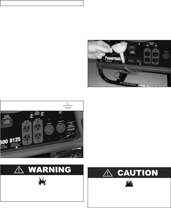
GROUNDING THE GENERATOR
The National Electric Code requires that this product be properly connected to an appropriate earth ground to help prevent electric shock. A ground terminal connected to the frame of the generator has been provided for this purpose. Connecting a length of heavy gauge (12 AWG min.) copper wire between the generator Ground Terminal and a copper rod driven into the ground should provide a suitable ground connection. However, consult with a local electrician to insure that local codes are being adhered to.
GROUND TERMINAL LOCATION:
Ground
Terminal
Do not use a pipe carrying combustible material as the ground source.
LUBRICATION
DO NOT attempt to start this engine without filling the crank case with the proper amount and type of oil. Your generator has been shipped from the factory without oil in the crankcase. Operating the unit without oil can damage the engine.
Fill the engine with oil according to the operator manual. For units with a dipstick, fill oil to the proper level. Units without a dipstick should be filled to the top of the opening of the oil fill.
LOW OIL SENSOR
The unit is equipped with a low oil sensor. If the oil level becomes lower than required, the sensor will activate a warning device or stop the engine.
If generator shuts off and the oil level is within specifications, check to see if generator is sitting at an angle that forces oil to shift. Place on an even surface to correct this. If engine fails to start, the oil level may not be sufficient to deactivate low oil level switch. Make sure the sump is completely full of oil.
FUEL
Fill the tank with clean, fresh unleaded automotive gasoline. Regular grade gasoline may be used provided a high octane rating is obtained (at least 85 pump octane). We recommend always using a fuel stabilizer. A fuel stabilizer will minimize the formulation of fuel gum deposits during storage. The fuel stabilizer can be added to the gasoline in the fuel tank, or into the gasoline in a storage container.
Do not overfill the tank. Keep maximum fuel level 1/4 inch below the top of the fuel tank. This will allow expansion in hot weather and prevent overflow.
English |
6 |
Customer Hotline 1-800-445-1805 |

GENERATOR FEATURES
A. Control Panel
NOTE: Total power drawn from all receptacles must not exceed the nameplate ratings.
B.120 V, 20 Ampere Receptacle
20 amps of current may be drawn from the receptacle.
However, total power drawn must be kept within nameplate ratings.
C.120 Volt, 30 Ampere Twistlock Receptacle
You may draw a maximum of 30 amps from this
receptacle. If other receptacles are used at the same time, total power used must be kept within nameplate ratings.
D.120/240 V, 30 Ampere Twistlock Receptacle
Maximum full load current may be drawn from the
120/240 volt receptacle, provided it is the only receptacle used. Total current must be limited to the nameplate rating. If the 120/240 volt receptacle is used along with the 120 volt receptacle, the total load drawn must not exceed the nameplate ratings.
E.Circuit Protectors
The receptacles are protected by an AC circuit protector.
If the generator is overloaded or an external short circuit occurs, the circuit protector will trip. If this occurs, disconnect all electrical loads and try to determine the cause of the problem before attempting to use the generator again. If
overloading causes the circuit protector to trip, reduce the load. NOTE: Continuous tripping of the circuit protector may cause damage to generator or equipment. The circuit protector may be reset by pushing the button of the protector.
F.Ground Terminal
G.Hour Meter
H.Engine On/Off/Start Switch
I.420 CC OHV Engine
J.Recoil Starter
K.Engine Choke Lever
L.Oil Filler Cap
M.Oil Drain Plug
N.6.5 Gallon Metal Fuel Tank
O.Fuel Tank Cap
P.Fuel Gauge
Q.Fuel Shut-Off
N O S G P E H 

K E C
Q 


 D
D

 F
F  A
A
J
I M R L B
English |
7 |
Customer Hotline 1-800-445-1805 |

GENERATOR FEATURES - DC USAGE
R. DC Usage
This Generator is equipped with a cigarette lighter style 12V DC receptacle. The maximum draw for this DC outlet is 8.3 Amps. The 12V DC receptacle is not intended for use to charge automotive batteries.
The cigarette lighter style receptacle permits the use of any electrical device designed for use in a 12V DC cigarette style outlet similar to ones found in automobiles. The electrical device has a power cord with a metal pin on the bottom and two leaf springs on the sides. Some common automotive type electrical devices are inflators, vacuum cleaners, chargers of various types and more.
To Use: Simply plug the electrical device power cord into the 12V DC outlet and ensure the power cord is securely in place. Use the device as instructed. Remove after use by simply pulling the power cord out of the receptacle.
S. DC Circuit Protector
A DC circuit protector has been provided to protect the circuit from overloads. If an overload occurs, the circuit protector will trip. The circuit protector may be reset by pushing the button of the protector.
English |
8 |
Customer Hotline 1-800-445-1805 |
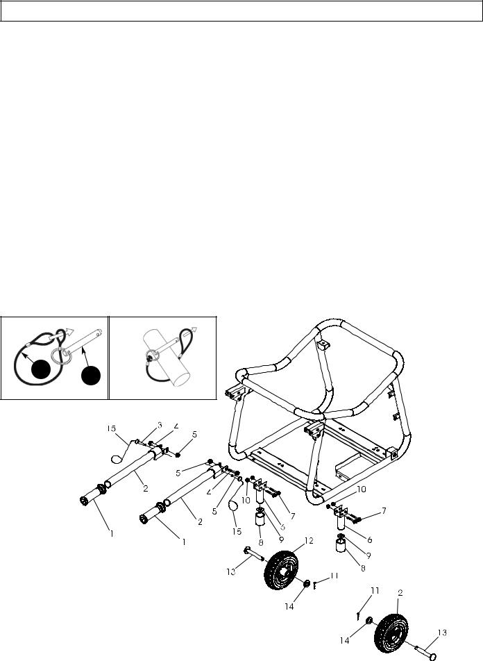
PORTABILITY KIT INSTALLATION
PORTABILITY KIT PART NUMBER: 0068294
TOOLS REQUIRED: 10mm and 13mm sockets and ratchets, block(s) of wood (minimum of 6” tall).
WHEEL INSTALLATION
1.Block up the alternator end of generator to install wheel kit.
2.Slide the wheel (item 12) onto the axle (item 13).
3.Slide axle through the wheel bracket on the carrier, with the offset side of the wheel hub against the wheel bracket.
4.Secure the wheel to the axle with the size 16 washer (item 14) and cotter pin (item 11).
5.Repeat above instructions for the remaining wheel.
FOOT INSTALLATION
1.Blocking up the engine side of the generator, assemble the foot bracket (items 6, 8, and 9) to the carrier (align with holes in tubing) using two M6 x 45 bolts (item 7). Thread M6 nuts (item 10) to the bolts to secure the assembly.
2.Repeat above instructions for the remaining foot.
HANDLE INSTALLATION
1.Slide M8 x 45 bolt (item 4) through handle (items 1 and 2) and handle bracket as shown in diagram and secure with M8 nut (item 5). Tighten until handle is securely clamped to the carrier.
2.Repeat above instructions for the remaining handle.
LOCKING HANDLE
1.Attach the lanyards (item 15) to the release pins (item 3) and carrier as shown in the illustration.
2.To lock the handle in the extended position, align the holes in the handle brackets with the holes in the carrier brackets and insert the release pins.
1 |
|
2 |
|
|
|
15
English |
9 |
Customer Hotline 1-800-445-1805 |
ELECTRIC START
This generator model is provided with both electric start and recoil start capabilities. The charger is a low amperage maintenance type charger. It will charge your battery as your generator runs. Avoid prolonged cranking, as it can damage the engine.
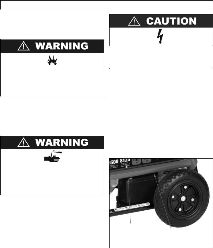
Storage batteries give off EXPLOSIVE hydrogen gas while charging. Do not allow smoking, open flames, sparks, or spark producing equipment in the area while charging.
The battery provided is a nominal 12 volt sealed rechargeable lead-acid battery and can be operated in any position without leakage. It’s convenient size offers a reduction over conventional batteries.
Length = 5.91 inches, Width = 3.43 inches, Height = 4.33 inches, Weight = 8.16 lbs 11AH Rating
Battery electrolyte fluid is comprised of sulfuric acid that can be very dangerous and cause severe burns. Do not allow this fluid to contact eyes, skin, clothing, etc. If contact or spillage does occur, flush the area with water immediately.
Battery Kit Parts List:
Refer to the parts list on pages 42 and 43.
Note: Brand New Generators are shipped with the Battery Connections disconnected. The Positive and Negative Terminals must be connected to the Battery before the Electric Start Feature will work.
Initial Battery Connection - Refer to the Installation Instructions Below.
Battery Removal & Installation:
Removal: Remove the nut and bolt from the negative and positive post, being careful not to short across the terminals. (Shorting the terminals together can cause sparks, damage to the battery or generator or even burns or explosions.) Always abide by the safety warnings provided with the battery. Remove the battery and re-cycle and dispose of properly.
•Do not short-circuit the battery terminals.
•Do not charge in a sealed container.
•Keep sparks, flame away.
Installation:
1.Place the battery in the position provided.
2.Place the bolts through the holes on the battery pan.
3.Place the bolts through the holes on the Hold-Down bracket.
4.Tighten down the Hold-Down assembly with the M6 nuts provided.
Hook up the new battery, or re-install the new battery, as follows: Remove vinyl caps from red and black wire terminals. Connect the Red wire to the positive (+) terminal and the Black wire to the negative (-) terminal with the bolt, nut, and washer provided. Make sure all connections are tight. Your battery is now connected and ready for use. Turn the key switch to crank the engine.
Note: Be sure Oil has been added to the engine as specified in the Owner's Manual.
POSITIVE (+)
TERMINAL (RED) NEGATIVE (-) TERMINAL (BLACK)
English |
10 |
Customer Hotline 1-800-445-1805 |
STARTING THE UNIT
Gasoline is very dangerous.
Serious injury or death may result from fire caused by gasoline contacting hot surfaces.
1.Do not fill fuel tank with engine running.
2.Do not spill fuel while refilling tank.
3.Do not mix oil with gasoline.
4.Follow all instructions and warnings in the operator manual.
PRE-START PREPARATION
Before starting the generator, check for loose or missing parts and for any damage which may have occurred during shipment.
This generator must not be operated without all factory installed heat shields in place. Failure to comply may cause the fuel tank to overheat and result in personal injury from fire.
STARTING THE ENGINE
1.Check oil level and fuel.
2.Disconnect all electrical loads from the unit.
3.Open fuel shut off valve.
4.Adjust choke as necessary.
5.Set the engine switch to the “ON" position.
6.Pull on the starter rope with fast steady pull. As the engine warms up, readjust the choke. On electric start models, turn the key switch to “START”. Release key switch after the engine starts.
Allow generator to run at no load for five minutes upon each initial start-up to permit engine and generator to stabilize.
•Provide adequate ventilation for toxic exhaust gases and cooling air flow.
•Do not start or run the generator in an enclosed area, even if door or windows are open.
•Engines give off carbon monoxide, an odorless, colorless, poison gas.
•Breathing carbon monoxide can cause nausea, fainting or death.
APPLYING LOAD
This unit has been pretested and adjusted to handle its full capacity. When starting the generator, disconnect all load. Apply load only after generator is running. Voltage is regulated via the engine speed adjusted at the factory for correct output. Readjusting will void warranty.
When applying a load, do not exceed the maximum wattage rating of the generator when using one or more receptacles. Also, do not exceed the amperage rating of any one receptacle.
Do not apply heavy electrical load during break-in period (the first two to three hours of operations).
SHUTTING THE GENERATOR OFF
1.Remove entire electrical load.
2.Let the engine run for two minutes without load.
3.Move the engine switch to the “OFF” position. (Turn the key switch to “OFF” on the electric start models).
4.Do not leave the generator until it has completely stopped.
5.Close the fuel shut off valve if the engine is to be put in storage or transported.
6.If a cover is used, do not install until unit has cooled.
7.If the generator will not be used again for an extended time period, refer to the SERVICE AND STORAGE section of this manual.
English |
11 |
Customer Hotline 1-800-445-1805 |

PERIODIC MAINTENANCE
|
ITEM |
NOTES |
Daily (Before |
Initial |
Every |
Every |
|
operation) |
20 hours |
50 hours |
100 hours |
||
|
|
|
||||
|
|
|
|
|
|
|
Spark Plug |
Check condition. Adjust gap and |
|
|
9 |
|
|
clean. Replace if necessary. |
|
|
|
|||
|
|
|
|
|
|
|
Engine Oil |
Check oil level. |
9 |
9 |
|
9 |
|
|
|
Replace. |
|
|
||
Air Filter |
Clean, replace if necessary. |
|
|
9 |
|
|
Fuel Filter |
Clean fuel filter and fuel tank strainer. |
|
|
|
9 |
|
Replace if necessary. |
|
|
|
|||
Fuel Line |
Check fuel hose for cracks or other |
9 |
|
|
|
|
damage. Replace if necessary. |
|
|
|
|||
|
|
|
|
|
|
|
Exhaust |
Check for leakage. Retighten or |
9 |
|
|
|
|
System |
replace gasket if necessary. |
|
|
|
||
|
|
Check muffler screen. Clean/replace |
|
|
|
9 |
|
|
|
|
|
||
|
|
if necessary. |
|
|
|
|
|
|
|
|
|
|
|
Carburetor |
Check choke operation. |
9 |
|
|
|
|
Starting |
Check recoil starter operation. |
9 |
|
|
|
|
System |
|
|
|
|||
|
|
|
|
|
|
|
Fittings/ |
Check. Replace if necessary. |
|
|
|
9 |
|
Fasteners |
|
|
|
|||
MAINTENANCE
SPARK PLUG
Remove the spark plug and clean the electrodes section with a wire brush or sandpaper. Next, set the gap at .028/.031 inches (0.7-0.8 mm) by adjusting the negative electrode. Replace the spark plug with correct torque: 14 ft-lb (20 N.m)
Replace with only the same type of spark plug which was removed. An improper spark plug can cause the engine to overheat, emit smoke, or otherwise perform poorly.
OIL TYPE
Use new good quality oil, SJ or later service category. The oil to be used depends upon the temperature at which the engine is operated:
Below 32° F (0° C) . . . . . . . . .SAE 10W, 10W-30, or 10W-40 32 to 80° F (0 to 25° C) . . . . . .SAE 20W, 10W-30, or 10W-40 80 to 95° F (25 to 35° C) . . . . .SAE 30W, 10W-30, or 10W-40 Above 95° F (35° C) . . . . . . . . . . . . . . . . . . . . . . . . .SAE 40W
OIL REPLACEMENT
1.Change oil while engine is warm.
2.Place the generator unit on a level surface.
3.Remove the oil filler cap.
4.Open the oil drain plug and let oil drain completely into a pan placed under the engine.
5.Check gaskets. Replace if required.
6.Reinstall the oil drain plug and refill engine with clean oil.
7.Replace the oil filler cap.
AIR FILTER CLEANING
1.Unscrew the air filter cover.
2.Remove filter element and wash well in solvent.
3.Pour a small amount of oil onto the filter element and gently squeeze out any excess oil.
4.Replace the filter element and air filter cover.
5.Be sure the filter cover seals properly all around.
FUEL VALVE FILTER CLEANING
1.Remove the cup at the bottom of the fuel valve with a small wrench.
2.Remove the fuel valve filter.
3.Clean and wash out the filter and cup and replace.
FUEL STRAINER CLEANING
1.Remove the plastic fuel strainer, located below the fuel tank cap.
2.Wash the strainer in solvent and replace.
English |
12 |
Customer Hotline 1-800-445-1805 |
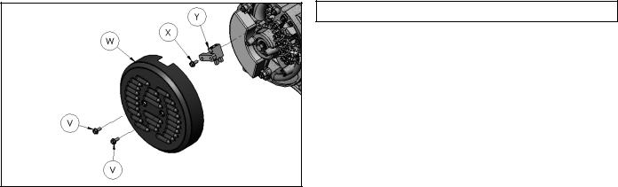
GENERATOR: Brushes
The brushes in the generator should be inspected once every year for chips and cracks. Brushes should be replaced when they are worn to 1/4 inch (7mm).
NOTE: Replace brushes in sets only, never separately. Replace only with brushes specified in parts list. Other brushes may appear to be identical but may have completely different mechanical and electrical characteristics.
INSPECTING THE BRUSHES:
1.Remove 2 screws (V) and end cover (W).
2.Remove screw (X) holding the brush module (Y).
3.Disconnect the blue (+) and yellow (-) brush wires from the tabs.
4.Replace if worn to 1/4 inch (7mm).
5.Do not over tighten screw.
QUICK STARTING TIPS FOR UNITS THAT HAVE BEEN SITTING FOR AWHILE:
If your unit has been sitting around for a long time period and is hard to start, try doing some of these easy steps before calling the Customer Hotline.
1.Check the oil level.
2.Replace the old fuel.
3.Change the spark plug.
4.Check the fuel lines. Make sure the fuel valve is open.
5.Check all generator parts for integrity.
6.Clean the Carburetor.
HEAT SHIELD:
Inspect to ensure that all heat shields and heat deflectors are intact and in place. Do not remove any parts or modify parts. Removing or modifying parts could cause serious damage to the unit.
ENGINE: Carburetor Icing
During the winter months, rare atmospheric conditions may develop which will cause an icing condition in the carburetor. If this develops, the engine may run rough, loose power, and may stall. Call Product Service for more information.
SERVICE AND STORAGE
INFREQUENT SERVICE
If the unit is used infrequently, difficult starting may result. To eliminate hard starting, follow these instructions:
1.Run the generator at least 30 minutes every month.
2.Run the generator, then close the fuel shut-off valve and allow the unit to run until the engine stops.
3.Move the engine switch to the “OFF” position.
LONG TERM STORAGE
When the generator set is not being operated or is being stored more than one month, follow these instructions:
1.Replenish engine oil to upper level.
2.Run the generator, then close the fuel shut-off valve and allow the unit to run until the engine stops.
3.Move the engine switch to the “OFF” position.
4.After the unit has cooled, drain gasoline from fuel tank, fuel line and carburetor.
5.Pour about one teaspoon of engine oil through the spark plug hole, pull the recoil starter several times and replace the plug. Then pull the starter until you feel the piston is on its compression stroke and leave it in that position.
This closes both the intake and exhaust valves to prevent the inside of the cylinder from rusting.
6.Cover the unit and store in a clean, dry place that is well ventilated away from open flame or sparks.
NOTE: We recommend always using a fuel stabilizer. A fuel stabilizer will minimize the formulation of fuel gum deposits during storage. The fuel stabilizer can be added to the gasoline in the fuel tank, or into the gasoline in a storage container.
English |
13 |
Customer Hotline 1-800-445-1805 |

ENGINE TROUBLESHOOTING
ENGINE SPECIFICATIONS
Type . . . . . . . . . . . . . . . . . . . . . . . . . . . . . . .4-stroke, single cylinder, gasoline, OHV Displacement . . . . . . . . . . . . . . . . . . . . . . . . . . . . . . . . . .420 cc, 25.63 cubic inches Maximum HP . . . . . . . . . . . . . . . . . . . . . . . . . . . . . . . . . . . . . . . .15 HP @ 3600 rpm Starting System . . . . . . . . . . . . . . . . . . . . . . . . . . . . . . . . .Recoil (electronic ignition) Driving System . . . . . . . . . . . . . . . . . . . . . . . . . . . . . .Direct coupling, tapered crank Oil Capacity . . . . . . . . . . . . . . . . . . . . . . . . . . . . . . . . . . . . . . . . . . . . . . . . . . . 37 oz. Spark Plug . . . . . . . . . . . . . . . . . . . . . . . . . . . . . . . . . . .NGK BPR6ES or equivalent Governor . . . . . . . . . . . . . . . . . . . . . . . . . . . . . . . . . . . . . . . .Mechanical (adjustable) Cooling System . . . . . . . . . . . . . . . . . . . . . . . . . . . . . . . . . . . . . . .Forced air cooling Carburetor Type . . . . . . . . . . . . . . . . . . . . . . . . . . . . . . . . . . . . . . . . . . . . . . . . .Float Air Cleaner Type . . . . . . . . . . . . . . . . . . . . . . . . . . . . . . . . . . . . . . . . .Foam element
English |
14 |
Customer Hotline 1-800-445-1805 |
SERVICE INFORMATION |
|
LIMITED WARRANTY |
|
|
|
CONTACT THE
PRAMAC AMERICA PRODUCT SERVICE DEPARTMENT AT 1-800-445-1805
or at www.powermate.com to obtain warranty service information or to order replacement parts or accessories.
HOW TO ORDER REPLACEMENT PARTS
Even quality built equipment such as the electric generator you have purchased, might need occasional replacement parts to maintain it in good condition over the years. To order replacement parts, please give the following information:
1.Model No. and Serial No. and all specifications shown on the Model No./Serial No. plate.
2.Part number or numbers as shown in the Parts List section.
3.A brief description of the trouble with the generator.
Pramac America, LLC 4970 Airport Road P. O. Box 6001 Kearney, NE 68847 1-800-445-1805 www.powermate.com
Warranty Coverage: Pramac America, LLC (the Company) warrants to the original retail customer in North America that it will repair or replace, free of charge, any parts found by the Company or its authorized service
representative to be defective in material or workmanship. This warranty covers the cost of replacement parts and labor for defects in material or workmanship.
Not Covered:
·Transportation charges for sending the product to the Company or its authorized service representative for warranty service, or for shipping repaired or replacement products back to the customer; these charges must be borne by the customer.
·If a separate operator's manual and engine warranty from the engine manufacturer is included with this product, only that warranty will apply to the engine.
·Damages caused by abuse or accident, and the effects of corrosion, erosion and normal wear and tear.
·Warranty is voided if the customer fails to install, maintain and operate the product in accordance with the instructions and recommendations of the Company set forth in the owner's manual, or if the product is used as rental equipment.
·The Company will not pay for repairs or adjustments to the product, or for any costs or labor, performed without the Company's prior authorization.
Warranty Period: Two (2) years from the date of purchase on products used solely for consumer applications; if a product is used for business or commercial applications, the warranty period will be limited to one (1) year from the date of purchase. For warranty service, the customer must provide dated proof of purchase and must notify the Company within the warranty period.
For warranty service: Call toll free 800-445-1805, or write to Pramac America, LLC, Product Services, 4970 Airport Road, P. O. Box 6001, Kearney, NE 68847.
EXCLUSIONS AND LIMITATIONS: THE COMPANY MAKES NO OTHER WARRANTY OF ANY KIND, EXPRESS OR IMPLIED. IMPLIED WARRANTIES, INCLUDING WARRANTIES OF MERCHANTABILITY AND OF FITNESS FOR A PARTICULAR PURPOSE, ARE HEREBY DISCLAIMED. THE WARRANTY SERVICE DESCRIBED ABOVE IS THE EXCLUSIVE REMEDY UNDER THIS WARRANTY; LIABILITY FOR INCIDENTAL AND CONSEQUENTIAL DAMAGES IS EXCLUDED TO THE EXTENT PERMITTED BY LAW.
This warranty gives you specific legal rights, and you may also have other rights which vary from state to state. Some states do not allow a disclaimer of implied warranties, or the exclusion or limitation of incidental and consequential damages, so the above disclaimers and exclusions may not apply to you.
English |
15 |
Customer Hotline 1-800-445-1805 |
 Loading...