


PM0418000
Insert
Additif
Adición
ELECTRIC GENERATOR - GROUPE ELECTROGENE - GENERADOR ELECTRICO
Thank you for selecting a Coleman® Powermate® Generator. The Coleman® Powermate® generator has been made to supply reliable, portable electrical power when utility power is not available. We hope you will enjoy your new generator. Welcome to our worldwide family of Coleman® Powermate® generator users.
Merci d'avoir choisi le groupe électrogène Coleman® Powermate®. Ce groupe électrogène Coleman® Powermate® a été conçu pour fournir le pouvoir électrique, portatif et fiable quand le pouvoir d'utilité n'est pas disponible. Nous espérons que votre groupe électrogène vous donnera entière satisfaction. Bienvenue dans la famille mondiale des utilisateurs de groupes électrogènes Coleman® Powermate®.
Gracias por seleccionar un generador Coleman® Powermate®. El generador Coleman® Powermate® ha sido diseñado para proporcionar energía eléctrica confiable y portátil cuando no hay servicio disponible de energía pública. Esperamos que disfrute de su nuevo generador. Bienvenido a nuestra familia de usuarios de generadores Coleman® Powermate® a nivel mundial.
IMPORTANT – Please make certain that persons who are to use this equipment thoroughly read and understand these instructions and any additional instructions provided prior to operation.
IMPORTANT - Prière de vous assurer que les personnes destinées à utiliser cet appareil ont pris soin d'en lire et d'en comprendre le mode d'emploi ou les directives avant de le mettre en marche.
IMPORTANTE. Asegúrese que las personas que utilizarán este equipo lean y entiendan completamente estas instrucciones y cualquier instrucción adicional proporcionada antes del funcionamiento.
www.powermate.com |
06/06 0064439 |

MAJOR GENERATOR FEATURES
*15 HP Kohler OHV engine
*Cast-iron cylinder sleeve
*Low oil sensor
*Receptacles on control panel
*CordKeeper™
*Automatic voltage regulator (AVR)
*8 gallon plastic fuel tank
*Spark arrester
*Portability Kit
CONTROL PANEL
A.120 V, 20 Ampere Duplex Receptacle
20 amps of current may be drawn from each half of the receptacle. However, total power drawn must be kept within nameplate ratings. These receptacles may be used along with the twistlock receptacle provided the generator is not overloaded.
B.120/240 V, 30 Ampere Twistlock Receptacle
A maximum of 30 amps may be drawn from the 120/240
volt receptacle, provided it is the only receptacle used. However, current must be limited to the nameplate rating. If the 120/240 volt receptacle is used along with the 120 volt receptacle, the total load drawn must not exceed the nameplate ratings.
C.Circuit Breakers
The receptacles are protected by an AC circuit breaker. If the generator is overloaded or an external short circuit occurs, the circuit breaker will trip. If this occurs, disconnect all electrical loads and try to determine the cause of the problem before attempting to use the generator again. If overloading causes the circuit breaker to trip, reduce the load. NOTE:
Continuous tripping of the circuit breaker may cause damage to generator or equipment. The circuit breaker may be reset by pushing the button of the breaker.
D.CordKeeper™ Restraint
The CordKeeper™ restraint is a unique feature used to
prevent plugs from being pulled out of the receptacles.
LIMITED WARRANTY
Warranty Coverage: Powermate Corporation (the Company) warrants to the original retail customer in North America that it will repair or replace, free of charge, any parts found by the Company or its authorized service representative to be defective in material or workmanship. This warranty covers the cost of replacement parts and labor for defects in material or workmanship.
Not Covered:
·Transportation charges for sending the product to the Company or its authorized service representative for warranty service, or for shipping repaired or replacement products back to the customer; these charges must be borne by the customer.
·Engine is covered exclusively by a separate warranty from the engine manufacturer, included with the engine Manual.
·Damages caused by abuse or accident, and the effects of corrosion, erosion and normal wear and tear.
·Warranty is voided if the customer fails to install, maintain and operate the product in accordance with the instructions and recommendations of the Company set forth in the owner's manual, or if the product is used as rental equipment.
·The Company will not pay for repairs or adjustments to the product, or for any costs or labor, performed without the Company's prior authorization.
Warranty Period: Two (2) years from the date of purchase on products used solely for consumer applications; if a product is used for business or commercial applications, the warranty period will be limited to one (1) year from the date of purchase. For warranty service, the customer must provide dated proof of purchase and must notify the Company within the warranty period.
For warranty service: Call toll free 800-445-1805, or write to Powermate Corporation, Product Services, 4970 Airport Road, P. O. Box 6001, Kearney, NE 68848.
EXCLUSIONS AND LIMITATIONS: THE COMPANY MAKES NO OTHER WARRANTY OF ANY KIND, EXPRESS OR IMPLIED. IMPLIED WARRANTIES, INCLUDING WARRANTIES OF MERCHANTABILITY AND OF FITNESS FOR A PARTICULAR PURPOSE, ARE HEREBY DISCLAIMED. THE WARRANTY SERVICE DESCRIBED ABOVE IS THE EXCLUSIVE REMEDY UNDER THIS WARRANTY; LIABILITY FOR INCIDENTAL AND CONSEQUENTIAL DAMAGES IS EXCLUDED TO THE EXTENT PERMITTED BY LAW.
This warranty gives you specific legal rights, and you may also have other rights which vary from state to state. Some states do not allow a disclaimer of implied warranties, or the exclusion or limitation of incidental and consequential damages, so the above disclaimers and exclusions may not apply to you.
|
|
English |
|
2 |
|||
|
|
PORTABILITY KIT INSTALLATION
TOOLS REQUIRED: 7/16”, 1/2” and 9/16" sockets and ratchets, block(s) of wood (minimum of 6” tall).
Refer to the parts list on page 12.
WHEEL INSTALLATION
1.Block up end of generator opposite the fuel tank cap to install wheel kit.
2.Insert wheel spacer (item 39) into the center of the wheel (item 28).
3.Slide 3/8 x 4.25” bolt (item 32) and 3/8 washer (item 27) through the wheel (item 28), then through the wheel bracket on the carrier, with the offset side of the wheel hub against the wheel bracket.
4.Thread 3/8 nyloc nut (item 33) onto the bolt and tighten to securely clamp the wheel assembly to the carrier.
5.Repeat above instructions for the remaining wheel.
FOOT INSTALLATION
1.Assemble the rubber feet (item 29) to the foot bracket (item 43) using a 1/4-20 x 1.5” bolt (item 11). Thread a 1/4 washer
(item 36) and a 1/4 nyloc nut (item 10) to the bolt to secure the assembly. Caution: Do not over tighten so that the foot material collapses.
2.Blocking up the alternator side of the generator, place the foot bracket under the carrier channel. Thread a 5/16-18 x 1” bolt (item 42) with a 5/16 wide washer (item 50) through the mounting holes and thread a 5/16 wide washer (item 50) and a 5/16 nyloc nut (item 13) to the bolt to secure the foot bracket to the carrier.
HANDLE INSTALLATION
1.Place handle (item 25) and spacer (item 46) on carrier on same end as feet, as shown in the diagram.
2.Slide 5/16 x 2.25” bolt (item 26) and 5/16 washers (item 12) through handle and handle bracket as shown in diagram and secure with 5/16” nyloc nut (item 13). Tighten until handle is securely clamped to the carrier.
3.Apply aerosol hairspray or similar adhesive to the handle (item 25), and then slide the handle grip (item 40) onto the handle. The aerosol hairspray will allow for easier assembly and will adhere the grip to the handle.
4.Insert cap (item 35) into end of handle (item 25).
5.Repeat above instructions for the remaining handle.
LOCKING HANDLE |
|
|
|
|
|
|
|
|
|
|
|
|
|
|
|
|
|
|
|
|
|
|
|
||
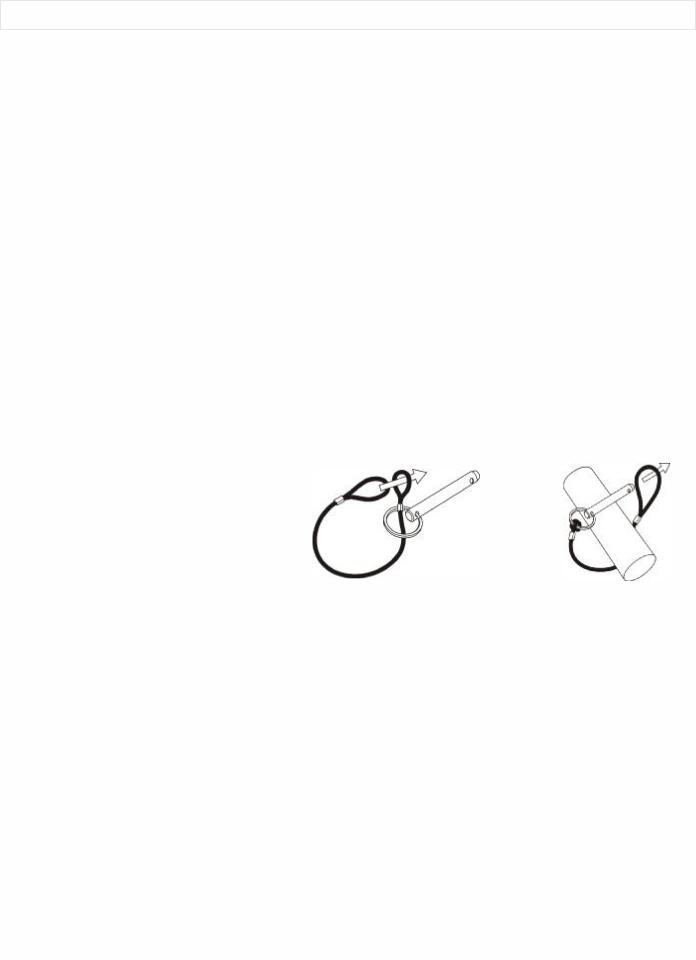
1. |
Attach the lanyards (item 30) to the release pins |
|
1 |
|
|
|
|
|
|
|
2 |
|
|
(item 34) and carrier as shown in the illustration. |
|
|
|
|
|
|
|
|
|
||
|
|
|
|
|
|
|
|
|
|
|
|
|
2. |
To lock the handle (item 25) in the extended |
|
|
|
|
|
|
|
|
|
|
|
|
position, align the holes in the handle brackets |
|
|
|
|
|
|
|
|
|
|
|
|
with the holes in the carrier brackets and insert |
|
|
|
|
|
|
|
|
|
|
|
|
the release pins (item 34). |
|
|
|
30 |
|
34 |
|
|
|
|
|
|
|
|
|
|
|
|
|
|
|
|||
|
|
|
|
|
|
|
|
|
|
|
|
|
English |
|
3 |
|
||
|
|
|

ELECTRIC START
This generator model is provided with both electric start and recoil start capabilities. The charger is a low amperage (1A) maintenance type charger. It will charge your battery as your generator runs. Avoid prolonged cranking, as it can damage the engine.
The battery provided is a nominal 12 volt sealed rechargeable lead-acid battery and can be operated in any position without leakage. It complies with non-spillable battery regulations. Its convenient size offers a 30% reduction over conventional batteries.
Length = 7.14 inches, Width = 3.03 inches, Height = 6.59 inches, Weight = 12.56 lbs 18AH Rating
UL Recognized
Battery Kit Parts List
Item |
Description |
|
Qty |
||
|
|
|
|
|
|
A |
|
*Bolt, M5 x M12 |
2 |
||
B. |
*Nut 5MM |
2 |
|||
C. |
*Washer Flat M5 |
2 |
|||
D. |
*Bolt, 1/4-20 X 8” |
2 |
|||
E. |
*Washer 1/4 |
2 |
|||
F. |
*Spacer |
2 |
|||
G. |
Hold Down bar (P/N 0036525.02) |
1 |
|||
H. |
*Wing nut, 1/4-20 |
2 |
|||
* These are standard parts available at your local hardware store.
Note: Brand New Generators are shipped with the Battery Connections disconnected. The Positive and Negative Terminals must be connected to the Battery before the Electric Start Feature will work.
Initial Battery Connection - Refer to the Installation Instructions Below.
Battery Removal & Installation:
Removal: Remove the nut and bolt from the negative and positive post, being careful not to short across the terminals. (Shorting the terminals together can cause sparks, damage to the battery or generator or even burns or explosions.) Always abide by the safety warnings provided with the battery. Remove the battery and re-cycle and dispose of properly.
Installation:
1.Place the battery in the position provided.
2.Place the bolts through the holes on the battery pan.
3.Place the bolts through the loops on the Hold-Down bracket.
4.Place the spacers and washers on the bolts.
5.Tighten down the Hold-Down assembly with the 1/4-20 nuts provided.
Note: Spacers may be removed depending on the battery height.
Hook up the new battery, or re-install the new battery, as follows: Remove vinyl caps from red and black wire terminals. Connect the Red 10 Gauge wire to the positive (+) terminal and the Black 10 Gauge wire to the negative (-) terminal with the bolt, nut, and washer provided. Make sure all connections are tight. Your battery is now connected and ready for use. Turn the key switch to crank the engine.
Note: Be sure Oil has been added to the engine as specified in the Owner's Manual.
•Do not short-circuit the battery terminals.
•Do not charge in a sealed container.
•Keep sparks, flame away.
|
|
English |
|
4 |
|||
|
|

CARACTÉRISTIQUES PRINCIPALES DU
GROUPE ELECTROGENE
*Moteur 15 HP Kohler OHV
*Chemise de cylindres en fonte
*Détecteur de bas niveau d'huile
*Prises sur tableau de commande
*CordKeeper™
*La tension automatique régulatrice
*Réservoir de carburant en plastique d'une contenance de 30.3 litres (8 gallons)
*Pare-étincelles
*Kit de transport
TABLEAU DE COMMANDE
A.Prise double de 120 V, 20 A
20 ampères de courant peuvent être dessinés de chaque
moitié de la prise. La charge totale doit cependant rester dans les limites indiquées sur la plaque signalétique. Ces prises peuvent s’utiliser en conjonction avec la prise à verrouillage à condition que le générateur ne soit pas surchargée.
B.Prise à verrouillage de 120/240 V, 30 A
Cette prise de 120/240 V fournit un maximum de 30 A à
condition que ce soit la seule utilisée. La charge totale doit par ailleurs rester dans les limites indiquées sur la plaque signalétique. Si la prise de 120/240 V est utilisée en conjonction avec les prises de 120 V, la charge totale ne doit pas dépasser les limites indiquées sur la plaque.
C.Disjoncteurs
Les prises sont protégées par un disjoncteur alternatif. En
cas de surcharge ou de court-circuit extérieur, le disjoncteur saute. Si cela se produit, débrancher tout appareil relié au groupe électrogène et essayer de déterminer la cause du problème avant d’essayer de le réutiliser. Si le disjoncteur saute en raison d’une surcharge, réduire la charge.
REMARQUE : Le groupe électrogène ou les appareils branchés dessus peuvent se trouver abîmés si le disjoncteur saute continuellement. Appuyer sur le bouton du disjoncteur pour le réenclencher.
D.CordKeeper™ la Restriction
Le CordKeeper™ la restriction est un dispositif unique qui
empêche la fiche de ressortir accidentellement d’une prise.
GARANTIE LIMITÉE
Couverture limitée : Powermate Corporation (la compagnie) garantit au revendeur d'origine en Amérique du Nord qu'elle réparera ou remplacera, sans frais, toutes les pièces que la compagnie ou que son représentant du service autorisé auront déterminé comme étant défectueuses du point de vue du matériel ou de la fabrication. La garantie couvre les coûts de remplacement des pièces et de main-d'œuvre pour tout défaut matériel ou de fabrication.
Ce qui n'est pas couvert :
·Les frais de transport pour envoyer le produit à la compagnie ou à son représentant du service autorisé pour effectuer le travail couvert par la garantie, les frais d'expédition au client des produits réparés ou remplacés. Ces frais doivent être assumés par le client.
·Le moteur est couvert exclusivement par une garantie distincte du fabricant du moteur. Cette garantie est incluse dans le guide d'utilisation du moteur.
·Les dommages causés par un abus ou un accident, et les effets de la corrosion, de l'érosion ainsi que de l'usure normale.
·La garantie est annulée si le client n'arrive pas à installer, garder et faire fonctionner le produit conformément aux directives et aux recommandations de la compagnie formulées dans le guide d'utilisation, ou si le produit est utilisé comme équipement de location.
·La compagnie ne paiera pas de réparation ou des ajustements au produit, ou pour les coûts ou main-d'œuvre, exécuté sans l'autorisation préalable de la compagnie.
Période couverte par la garantie : Deux (2) ans à partir de la date d'achat sur les produits utilisés uniquement pour les applications de consommateur. Si le produit est utilisé à des fins d'affaires ou commerciales, la période couverte par la garantie se limite à un (1) an à partir de la date d'achat. En ce qui concerne l'entretien couvert par la garantie, le client doit présenter une preuve de la date d'achat et il doit aviser la compagnie au cours de la période couverte par la garantie.
Pour tout ce qui touche l'entretien couvert par la garantie : Composez sans frais le 1 800 445-1805, ou écrivez à
Powermate Corporation, Product Services, 4970 Airport Road, P. O. Box 6001, Kearney, NE 68848 É.-U.
EXCLUSIONS ET LIMITATIONS : LA COMPAGNIE NE PRÉSENTE AUCUNE AUTRE GARANTIE, EXPRESSE OU IMPLICITE. LES GARANTIES IMPLICITES, INCLUANT LES GARANTIES DE QUALITÉ MARCHANDE ET DE CONFORMITÉ AUX BESOINS SONT, PAR LA PRÉSENTE, ABANDONNÉES. L'ENTRETIEN COUVERT PAR LA GARANTIE DÉCRIT CI-DESSUS EST UN RECOURS EXCLUSIF EN VERTU DE CETTE GARANTIE. LA RESPONSABILITÉ POUR DES DOMMAGES ACCESSOIRES ET INDIRECTS EST EXCLUE JUSQU'À LA LIMITE AURORISÉE PAR LA LOI.
Cette garantie vous donne des droits spécifiques reconnus par la loi. Vous pouvez également bénéficier de certains autres droits, lesquels varient d'une province (État) à l'autre. Certaines provinces (ou certains États) n'autorisent pas de clauses de renonciation des garanties implicites ou de limites à l'égard de dommages accessoires ou indirects, ainsi, les clauses de renonciation et les exclusions ci-dessus peuvent ne pas s'appliquer à vous.
|
|
|
Français |
5 |
|
|
|
|
 Loading...