


MODEL : PBV5PW1
PART : 77551
COPPERHEAD
WOOD PELLET VERTICAL
SMOKER (5-SERIES)
SAVE THESE INSTRUCTIONS!
MANUAL MUST BE READ BEFORE OPERATING!
ASSEMBLY AND OPERATION INSTRUCTIONS
WARNING: Please read the entire manual before installation and use of this electric, pellet fuel burning appliance. Failure to follow these instructions could result in property damage, bodily injury or even death.
Contact local building or fire officials about restrictions and installation inspection requirements in your area.
RECIPES |
INCLUDED |
|
|
||
INBACK |
OFMANUAL |
|
|
|
|

SAFETY INFORMATION
A MAJOR CAUSE OF FIRES ARE A RESULT OF POOR MAINTENANCE AND A FAILURE TO MAINTAIN REQUIRED CLEARANCES (AIR SPACES) TO COMBUSTIBLE MATERIALS. IT IS OF UTMOST IMPORTANCE THAT THIS PRODUCT BE INSTALLED ONLY IN ACCORDANCE WITH THESE INSTRUCTIONS.
Please read and understand this entire manual before attempting to assemble, operate or install the product. This will ensure you receive the most enjoyable and trouble-free operation of your new wood pellet smoker. We also advise you retain this manual for future reference.
DANGERS AND WARNINGS
You must contact your local home association, building or fire officials, or authority having jurisdiction, to obtain the necessary permits, permission or information on any installation restrictions, such as any smoker being installed on a combustible surface, inspection requirements or even ability to use, in your area.
1.A minimum clearance of 305mm (12 inches) from combustible constructions to the sides of the smoker, and 305mm (12 inches) from the back of the smoker to combustible constructions must be maintained. Any limitations joining of two or more parts to constitute an assembly, such as installation of support legs, enclosures and the like. Do not use this appliance indoors, in an enclosed unventilated area, under an overhead combustible ceiling or overhang. Keep your smoker in an area clear and free from combustible materials, gasoline and other flammable vapors and liquids.
Should a grease fire occur, turn the smoker off and leave the cabinet door closed until the fire is out. Do not unplug the power cord. Do not throw water on. Do not try to smother the fire. Use of an all-class (class ABC) approved fire extinguisher is valuable to keep on site. If an uncontrolled fire does occur, call the Fire Department.
2.Keep electrical supply cords and the fuel away from heated surfaces. Do not use your smoker in the rain or around any water source.
3.After a period of storage, or non-use, check the burn pot for obstructions, the hopper for foreign objects, and any air blockage around the fan intake or rear barrel exhaust holes. Clean before use. Regular care and maintenance is required to prolong the lifespan of your unit. If the smoker is stored outside during the rainy season or seasons of high humidity, care should be taken to insure that water does not get into the hopper. When wet or exposed to high humidity, wood pellets will expand greatly, decompose, and may jam the feed system. Always disconnect the power, before performing any service or maintenance.
Do not transport your smoker while in use or while the smoker is hot. Ensure the fire is completely out and that the smoker is completely cool to the touch before moving.
4.It is recommended to use heat-resistant barbecue mitts or gloves when operating the smoker. Do not use accessories not specified for use with this appliance. Do not put a barbecue cover or anything flammable in the storage space area under the barbecue. Parts of the barbecue may be very hot, and serious injury may occur. Keep young children and pets away while in use.
This appliance is not recommended for children, persons with reduced physical, sensory or mental capabilities, or lack of experience and knowledge, unless they are under direct supervision or instruction by a person responsible for their safety.
5.To prevent fingers, clothing or other objects from coming in contact with the auger feed system, the appliance is equipped with a metal safety screen, mounted to the interior of the hopper. This screen must not be removed unless directed by Customer Service or an authorized dealer.
6.Do not enlarge igniter holes or burn pots. Failure to follow this warning could lead to a fire hazard and bodily harm and will void your warranty.
3

DISPOSAL OF ASHES
Ashes should be placed in a metal container with a tight-fitting lid. The closed container of ashes should be placed on a noncombustible floor or on the ground, well away from all combustible materials, pending final disposal. When ashes are disposed by burial in soil, or otherwise locally dispersed, they should be retained in a closed container until all cinders have thoroughly cooled.
WOOD PELLET FUEL
This pellet cooking appliance is designed and approved for pelletized, all natural, wood fuel only. Any other type of fuel burned in this appliance will void the warranty and safety warning. You must only use all natural wood pellets, designed for burning in pellet barbecue smokers. Do not use fuel labelled as having additives.
Do not use lava rock, wood chunks, charcoal, spirit, petrol, gasoline, lighter-fluid or kerosene for lighting or refreshing a fire in your smoker. Keep all such substances and liquids well away from appliance when in use.
At this time of printing, there is no industry standard for barbecue wood pellets, although most pellet mills use the same standards to make wood pellets for domestic use. Further information, can be found at www.pelletheat.org or the Pellet Fuel Institute.
Contact your local dealer on the quality of pellets in your area, and for information on brand quality. As there is no control over the quality of pellets used with the appliance, Dansons Inc. assumes no liability caused by the quality of fuel.
CREOSOTE
Creosote, or soot, is a tar-like substance. When burning, it produces black smoke with a residue which is also black in color. Soot or creosote is formed when the appliance is operated incorrectly, such as: blockage of the burn pot, blockage of the combustion fan, failure to clean and maintain the burn area, or poor air-to-fuel combustion.
It is dangerous to operate this appliance should the flame become dark, sooty, or if the burn pot is overfilled with pellets. When ignited, this creosote makes an extremely hot and uncontrolled fire, similar to a grease fire. Should this happen, turn the unit off, let it cool completely, then inspect for maintenance and cleaning. It commonly accumulates along exhaust areas.
If creosote has formed within the unit; allow the unit to warm up at a low temperature, turn off the appliance, then wipe away any formation with a hand towel. Similar to tar, it is much easier to clean when warm, as it becomes liquid.
CARBON MONOXIDE (“the silent killer”)
Carbon monoxide is a colorless, odorless, tasteless gas produced by burning gas, wood, propane, charcoal or other fuel. Carbon monoxide reduces the blood’s ability to carry oxygen. Low blood oxygen levels can result in headaches, dizziness, weakness, nausea, vomiting, sleepiness, confusion, loss of consciousness or death. Follow these guidelines to prevent this colorless, odorless gas from poisoning you, your family, or others:
•See a doctor if you or others develop cold or flu-like symptoms while cooking or in the vicinity of the appliance. Carbon monoxide poisoning, which can easily be mistaken for a cold or flu, is often detected too late.
•Alcohol consumption and drug use increase the effects of carbon monoxide poisoning.
•Carbon monoxide is especially toxic to mother and child during pregnancy, infants, the elderly, smokers, and people with blood or circulatory system problems, such as anemia, or heart disease.
SAFETY LISTING
In accordance with the procedures and specifications listed in the UL Subject 2728-2009 "pellet fuel cooking appliances" and ULC/ORD C272 and Canadian CSA C22.2 #3 "for electrical features of fuel burning equipment." Pit Boss Grills pellet cooking appliances have been independently tested and listed by Intertek (an accredited testing laboratory) to ETL, UL, ULC and CSA standards.
This product has been assessed and meets EU (European Economic Area) safety, health and environmental protection requirements. Please read the silver safety label found on the back of the unit.
4

COPYRIGHT NOTICE
Copyright 2017. All right reserved. No part of this manual may be copied, transmitted, transcribed, stored in a retrieval system, in any form or by any means without expressed written permission of,
Dansons Inc.
3411 North 5th Avenue, Suite 500, Phoenix, AZ, USA 85013 sales@pitboss-grills.com | service@pitboss-grills.com www.pitboss-grills.com
Toll-Free: 1-877-303-3134, Fax: 1-877-303-3135
5

TABLE OF CONTENTS
Safety Information ........................................................... |
3 |
Parts & Specs...................................................................... |
7 |
Assembly Preparation...................................................... |
8 |
Assembly Instructions |
|
Mounting The Support Legs To Main Cabinet........................ |
8 |
Securing The Control Panel To Support Legs.......................... |
8 |
Mounting The Support Panels................................................... |
9 |
Securing The Support Bar........................................................... |
9 |
Mounting The Grease Exhaust Tube........................................ |
9 |
Attaching The Heat Shield.......................................................... |
9 |
Mounting The Power Cord Bracket......................................... |
10 |
Securing The Grease Tray Brackets......................................... |
10 |
Placing The Grease Tray............................................................. |
10 |
Attaching The Hopper Clean-Out Door Handle................... |
10 |
Mounting The Hopper Handles................................................ |
11 |
Securing The Chimney................................................................ |
11 |
Installing The Lid Stopper.......................................................... |
11 |
Mounting The Cabinet Door Handle, Door Latch................. |
11 |
Installing The Cooking Components ...................................... |
12 |
Connecting To A Power Source................................................. |
12 |
Operating Instructions |
|
Smoker Environment.................................................................. |
13 |
Smoker Temperature Ranges................................................... |
14 |
Understanding The Control Board........................................... |
15 |
Understanding The Probes........................................................ |
15 |
Hopper Priming Procedure...................................................... |
16 |
First Use – Smoker Burn-Off................................................... |
16 |
Preheating.................................................................................... |
16 |
Automatic Start-Up Procedure............................................... |
16 |
Manual Start-Up Procedure...................................................... |
17 |
Shutting Off Your Smoker.......................................................... |
17 |
Care & Maintenance........................................................ |
18 |
Using Wood Pellet Fuel................................................... |
19 |
Cooking Guidelines........................................................... |
19 |
Tips & Techniques............................................................. |
21 |
Troubleshooting .............................................................. |
22 |
Electrical Wire Diagram.................................................. |
24 |
Replacement Parts |
|
Smoker Replacement Parts ..................................................... |
25 |
Electrical Replacement Parts.................................................... |
26 |
Warranty |
|
Conditions..................................................................................... |
26 |
Exceptions.................................................................................... |
27 |
Ordering Replacement Parts.................................................... |
27 |
Contact Customer Service......................................................... |
27 |
Warranty Service ........................................................................ |
27 |
Accessories Sold Separately.......................................... |
28 |
Recipes............................................................................... |
29 |
6
|
|
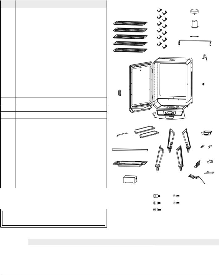
PARTS & SPECS |
|
|
|
|
|
Part# |
Description |
|
2 |
1 |
Cooking Grids (x5) |
|
3 |
2 |
Cooking Grid Support Brackets (x12) |
1 |
|
|
|
|
4 |
3 |
Chimney Cap (x1) |
|
|
|
|
||
4 |
Chimney Stack (x1) |
|
5 5-1 |
5 |
Hopper Handle, Short, Long (x2) |
|
|
|
5-2 |
||
6 |
Lid Stopper (x1) |
|
|
|
|
||
7 |
Main Cabinet (x1) |
|
6 |
8 |
Cabinet Door Handle (x1) |
|
|
|
7 |
||
9 |
Cabinet Door Latch (x1) |
|
|
10 |
Power Cord Bracket (x1) |
|
|
11 |
Support Panel (x2) |
|
9 |
12 |
Support Bar (x1) |
|
|
|
8 |
||
13 |
Water Pan (x1) |
|
|
|
|
||
14Flame Tamer (x1)
15Support Leg With Wheel (x4)
16Grease Tray (x1)
17 |
Grease Tray Brackets (x2) |
|
|
11 |
|
|
|
|
|
|
||
18 |
Wire Components Housing (x1) |
|
10 |
|
|
15 |
|
|
16 |
|||
|
|
|
|
|
||||||||
|
|
|
|
|
|
|||||||
19 |
Grease Exhaust Tube (x1) |
|
|
|
|
|
|
|
|
|
||
20 |
Heat Shield (x1) |
|
12 |
|
|
|
|
|
|
17 |
||
21 |
Meat Probe (x1) |
|
|
|
15-2 |
|
15-4 |
|
17-1 17-2 |
|||
|
|
|
|
|
||||||||
|
A |
Door Knob (x1) |
|
13 |
|
|
|
18 |
19 |
|||
|
|
|
|
|
|
|||||||
|
B |
¼–20x½" Screw (x12) |
|
|
|
|
|
|
|
20 |
||
|
|
|
|
|
|
|
|
|||||
|
C |
¼–20x⅝" Screw (x4) |
|
14 |
15-1 |
|
15-3 |
|
|
|||
|
|
|
|
|
||||||||
|
D |
#10–24x½" Screw (x36) |
|
|
|
21 |
||||||
|
|
|
|
|
|
|
||||||
|
E |
#10–24x⅓" Screw (x2) |
|
|
|
|
|
|
|
|||
|
|
|
|
|
|
|
|
|
||||
NOTE: Due to ongoing product development, parts are subject to change |
|
|
|
|
|
|
|
|
||||
|
|
A |
D |
|
|
|
|
|||||
without notice. Contact Customer Service if parts are missing when |
|
|
|
|
|
|
||||||
|
|
|
|
|
|
|
|
|||||
assembling the unit. |
|
|
B |
E |
|
|
|
|
||||
|
|
|
|
|
|
|
C |
|
|
|
|
|
|
|
|
|
|
|
|
|
|
|
|
||
|
PB – ELECTRIC REQUIREMENTS |
|
|
|
|
|
|
|||||
|
|
|
|
|
|
|
|
|
||||
|
|
|
|
|
|
|
|
|
||||
120V, 2.1AMP, 60HZ, 250W, 3-PRONG GROUNDED PLUG
MODEL |
UNIT ASSEMBLED (WxHxD) |
UNIT WEIGHT |
COOKING AREA |
TEMP. RANGE |
DIGITAL FEATURES |
|
|
|
|
|
|
|
Ten temperature |
PB |
PBV5PW1 |
734mm x 1,350mm x 709mm |
58.0 kg |
Cubic Cooking: 0.13 m3 / 4.6 ft3 |
65-215°C |
presets, start-up and |
/ 28 ¾” x 53” x 27” |
/127.0 lb |
TOTAL - 9,762 cm² / 1,513 sq. in. |
/ 150-420°F |
cool-down cycles, |
||
|
|
|
|
|
|
electric igniter |
|
|
|
|
|
|
|
7
ASSEMBLY PREPARATION
Parts are located throughout the shipping carton, including underneath the vertical smoker. Inspect the unit, parts, and hardware blister pack after removing from the protective shipping carton. Before assembly of product, review all parts and reference the parts list. If any part is missing or damaged, do not attempt to assemble. Shipping damage is not covered under warranty. Contact your dealer or Pit Boss Customer Service for parts.
IMPORTANT: To ease installation, using two people is helpful (but not necessary) when assembling this unit.
Tools required for assembly: screwdriver and level. Tools not included.
ASSEMBLY INSTRUCTIONS
IMPORTANT: It is advised to read each step entirely before starting assembly on instructions. Do not tighten screws completely until all screws for that step have been installed, or unless otherwise mentioned.
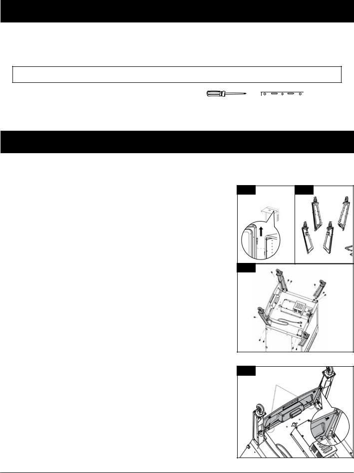
1. |
MOUNTING THE SUPPORT LEGS TO MAIN CABINET |
1A |
1B |
|
||
|
Parts Required: |
|
15-1 |
15-3 |
||
|
1 |
x |
Main Cabinet (#7) |
|
|
|
|
4 |
x Support Leg With Wheel (#15) |
|
|
|
|
|
12 |
x |
¼–20x½" Screw (#B) |
|
|
|
|
Installation: |
|
|
|
||
|
• |
Place a piece of cardboard on the floor to prevent scratching the unit |
|
15-2 |
15-4 |
|
|
|
and parts during assembly. First, lift the main cabinet door off the |
1C |
|
|
|
|
|
hinges, and place aside. Note illustration 1A |
15-3 |
|
||
|
|
|
|
|||
|
• |
Next, flip the main cabinet, bottom side pointed upward, on the |
|
|
15-4 |
|
|
|
cardboard. Prepare the four support legs for installation, arranging |
|
|
|
|
|
|
the labelled legs as shown in illustration 1B. |
|
|
|
|
|
IMPORTANT: The four support legs must be arranged correctly to be |
|
15-1 |
|
||
|
|
|
|
|||
|
able to properly install the support panels and support bar in later |
|
|
|
||
|
steps. |
|
|
|
|
|
|
• |
Mount one support leg to the smoke cabinet using three screws. Repeat |
|
|
15-2 |
|
|
|
installation for the other three support legs. Note illustration 1C. |
|
|
||
|
|
|
|
|
||
2. |
SECURING THE CONTROL BOARD TO SUPPORT LEGS |
2 |
|
|
||
|
Parts Required: |
|
2A |
|
||
|
2 |
x |
#10–24x½" Screw (#D) |
|
|
|
|
Installation: |
|
|
|
||
|
• |
Near the Control Board, loosen the two screws connecting the front |
|
|
|
|
|
|
panel to the main cabinet. Note 2A. |
|
|
2B |
|
|
• |
Next, using another two screws, secure the front panel sides to the |
|
|
|
|
|
|
front-facing support legs. Once these screws are tight, re-tighten the |
|
|
|
|
|
|
two screws that were previously loosened. Note 2B. |
|
|
|
|
|
|
|
|
|
|
8 |
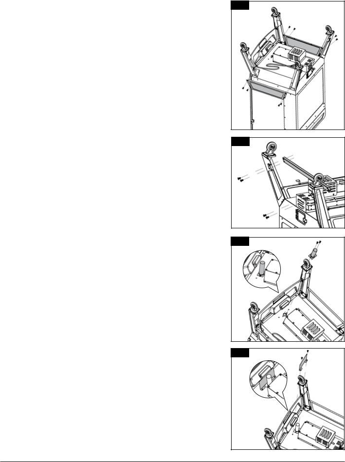
3. MOUNTING THE SUPPORT PANELS
Parts Required:
2 |
x |
Support Panel (#11) |
8 |
x |
#10–24x½" Screw (#D) |
Installation:
•Install one support panel to the side of the unit between a front and back support leg. Secure using two screws on each side. Ensure the flat side of the support plate is facing outwards. Repeat the same installation to mount the other support panel. Note illustration for support panel arrangement.
NOTE: The support panel with two holes along the bottom should be on the same side of the unit as the power cord exits the control board (left side). This is important for later steps.
4. SECURING THE SUPPORT BAR
Parts Required:
1 |
x |
Support Bar (#12) |
4 |
x |
#10–24x½" Screw (#D) |
Installation:
•Install the support bar to the rear of the unit between the two rear support legs. Secure using two screws on each side. Ensure the support bar is placed on the underside of the main cabinet, facing inwards. Note illustration for support bar arrangement.
5. MOUNTING THE GREASE EXHAUST TUBE
Parts Required:
1x Grease Exhaust Tube (#189
2x #10–24x⅓" Screw (#E)
Installation:
•Mount the grease exhaust tube to the underside of the main cabinet using two screws.
IMPORTANT: Ensure there is a good seal to the main cabinet, as grease will come from the main cabinet, flow through the exhaust tube, and exit into the grease tray.
6. ATTACHING THE HEAT SHIELD
Parts Required:
1x Heat Shield (#20)
2x #10–24x½" Screw (#D)
Installation:
•Position the heat shield between the control board and the grease exhaust tube. Secure using a screw on each side.
IMPORTANT:Ifthispartisnotinstalledcorrectly,theheatand/orsplatter from the grease exhaust tube may cause damage to the control board. Grease damage to the rear of control board is not covered by warranty.
3
4
5 |
6 |
9
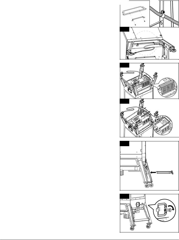
7. MOUNTING THE POWER CORD BRACKET
Parts Required:
1x Power Cord Bracket (#10)
2x #10–24x½" Screw (#D)
Installation:
•Locate the two holes on the bottom of the (left side) support bracket. Mount the power cord bracket to the support bracket using two screws as shown in 7A.
•Next, loosen the nut on the pre-mounted clip bracket and guide the power cord through the clip bracket. Once through, tighten the nut, and wrap the power cord on the bracket until unit is in use. Note 7B, 7C.
8.SECURING THE GREASE TRAY BRACKETS
Parts Required:
1x Wire Components Housing (#18)
2x Grease Tray Brackets (#17)
6 x #10–24x½" Screw (#D)
Installation:
•First, mount the wire components housing onto the base of the auger housing using two screws in each bracket. Note 8A.
•Secure the grease tray brackets onto the base of the auger housing and the wire components housing using two screws in each bracket. Note illustration 8B for proper placement.
NOTE: The diveted end of the brackets should face the control board.
•Fully-tighten all screws on the cart base. Next, carefully turn the unit into an upright position, with the wheels are on the bottom.
9.PLACING THE GREASE TRAY
Parts Required:
1 |
x Grease Tray (#16) |
Installation:
•Slide the grease tray into the grease tray brackets on the front underside of the main cabinet, under the control board.
NOTE: The grease tray is completely inserted once the front of the tray is pushed in as far as it can go, with no gap between the grease tray and the front panel.
7A |
|
7B |
7C
8A |
8B |
17-1 |
17-2 |
9 |
10. ATTACHING THE HOPPER CLEAN-OUT DOOR KNOB |
10 |
|||
Parts Required: |
||||
|
||||
1 |
x |
Door Knob (#A) |
|
|
Installation: |
|
|||
• Attach the door knob to the hopper clean-out door by rotating the |
|
|||
|
part into the hole on the door. |
|
||
|
|
|
10 |
|

11. MOUNTING THE HOPPER HANDLES
Parts Required:
1 |
x |
Long Hopper Handle (#5-2) |
4 |
x |
¼–20x⅝" Screw (#C) |
1x Short Hopper Handle (#5-1)
2x #10–24x½" Screw (#D)
Installation:
•Mount the hopper handle onto the back side of the hopper using four screws (#C). Note correct position in illustration 11A, with handle on top.
•Mount the hopper lid handle onto the back side of the hopper lid using two screws (#D). Note 11B.
12.SECURING THE CHIMNEY
Parts Required:
1 |
x |
Chimney Cap (#3) |
1 |
x |
Chimney Stack (#4) |
4 |
x |
#10–24x½" Screw (#D) |
Installation:
•Locate the chimney opening on the top of the main cabinet. From the outside, secure the chimney to the top panel using four screws. The screw will fasten to the self-clinching nut on the inside of the cabinet. Next, twist the chimney cap onto the top.
NOTE: Adjust the chimney cap to affect the airflow inside the main grill. If cooking at low temperature, keep the cap more open.
13. INSTALLING THE LID STOPPER
Parts Required:
1x Lid Stopper (#6)
2x #10–24x½" Screw (#D)
Installation:
•Install the lid stopper onto the top of the main cabinet near the hopper lid, using one screw on the top side and one screw on the inside edge between the hopper lid hinges.
14.MOUNTING THE CABINET DOOR HANDLE, DOOR LATCH
Parts Required:
1 |
x Cabinet Door Handle (#8) |
|
1 |
x |
Cabinet Door Latch (#9) |
4 |
x |
#10–24x½" Screw (#D) |
Installation:
•First, remount cabinet door to the main cabinet by aligning and securing both hinges. Ensure the door is mounted correctly by testing it opens freely. Note 14A.
•Mount the cabinet door handle onto the front side of the cabinet door using two screws. Note correct direction in 14B. Mount the cabinet door latch onto the exterior side of the main cabinet using two screws. Note 14C.
11A
5-2
11B
5-1
12
13 |
14 |
14A |
14C |
14B |
11
 Loading...