


MODEL / MODELO: PBMEMU1
PART / PARTE: 75952
MEMPHIS ULTIMATE
GAS AND CHARCOAL
COMBO GRILL WITH
ELECTRIC SMOKER
SAVE THESE INSTRUCTIONS! MANUAL
MUST BE READ BEFORE OPERATING!
1.Do not store or use gasoline or other flammable liquids or vapors in the vicinity of this or any other appliance!
2.An LP cylinder not connected for use shall not be stored in the vicinity of this or any other appliance.
Propane tank not included
INSTRUCTIONS AND RECIPES | INSTRUCTIONS ET RECETTES | INSTRUCCIONES Y RECETAS
WARNING: Please read the entire manual before installation and use of this electric appliance. Failure to follow these instructions could result in property damage, bodily injury or even death. Contact local building or fire officials about restrictions and installation inspection requirements in your area.
AVERTISSEMENT : Veuillez lire l'intégralité du manuel avant l'installation et |
l'utilisation |
de cet |
||
appareil |
électrique. Ne pas suivre ces instructions peut entraîner des dégâts matériels ou des blessures |
|||
corporelles |
graves pouvant aller jusqu'à la mort. Contactez les responsables locaux de la construction ou |
|||
des incendies au sujet des restrictions et des exigences d'inspection de l'installation dans votre région. |
||||
ADVERTENCI: Lea el manual completo antes de instalar y utilizar este aparato |
eléctrico. Incumplir |
|||
estas |
instrucciones podría causar daños materiales, lesiones corporales, e |
incluso la |
muerte. |
|
Consulte a |
sus funcionarios locales de construcción y control de incendios para informarse sobre las |
|||
restricciones y los requisitos de inspección de instalaciones en su región. |
|
|
||
RECIPES |
INCLUDED |
|
|
INCLUSES |
|
RECETTES |
||
RECETAS |
INCLUIDAS |
|
|
||

SAFETY INFORMATION
GRILL GENERAL WARNINGS
•Never use or store gasoline, lighter fluid, paint thinner, or other flammable vapors and liquids or combustible materials in or near your grill.
•Never use charcoal, lava rocks or wood briquets in a gas grill. Flavoring chips must be contained in a metal smoking box to contain ash and prevent fires.
•Ensure flames come out of all burner ports at each use. Spiders and insects like to build nests in burner tubes. Blocked burner tubes can prevent gas flow to the burners and could result in a burner tube fire or fire beneath the grill.
•Position your grill outdoors on a non-combustible level surface in a well ventilated location. Maintain a minimum clearance of 36 inches (91 cm) between all sides of grill, deck railings, walls or other combustible material. Not adhering to these clearances may prevent proper ventilation and can increase the risk of a fire and/ or property damage, which could also result in personal injury.
•DO NOT use grill under overhead unprotected combustible construction. •DO NOT leave the grill unattended while ON or in use.
•DO NOT use or install this grill in or on a recreational vehicle and/or boat.
•DO NOT allow grease or hot drippings to fall on hose and regulator assembly. If this occurs, turn gas supply OFF at once. Empty grease tray/cup and clean the hose and regulator assembly and inspect for damage before use.
•FOR OUTDOOR USE ONLY. DO NOT operate indoors or in an enclosed area such as a garage, shed or breezeway.
•Keep children and pets away from hot grill. DO NOT allow children to use or play near this grill. •DO NOT use water on a grease fire. Closing the lid to extinguish a grease fire is not possible.
•DO NOT allow the gas hose to come in contact with hot surfaces. Redirect the gas hose if necessary. •DO NOT block ventilation areas in sides, back or cart compartment of grill.
•Never check for leaks using a match or open flame.
•DO NOT store items in cart that can catch fire or damage your grill (such as swimming pool supplies/ chemicals, table cloth, wood chips).
•The outdoor cooking gas appliance, when installed, must be electrically grounded in accordance with local codes or, in the absence of local codes, with the National Electrical Code, ANSI/NFPA 70, or the Canadian
•Electrical Code, Part 1, CSA C22.1.
Keep any electrical supply cord and the fuel supply hose away from any heated surfaces.
Use only a Ground Fault Interrupter (GFI) protected circuit with this outdoor cooking gas appliance.
•Longer, detachable power-supply cords or extension cords are available and may be used if care is exercised in their use, based on the following requirements.
•If a longer, detachable power-supply cord or extension cord is used, the marked electrical rating of the cord set or extension cord should be at least as great as the electrical rating of the appliance.
•The extension cord must be a grounding -type 3-wire cord.
•Outdoor extension cords must be used with outdoor use products and are marked with suffix “W” and with the statement “Suitable for Use with Outdoor Appliances.”
WARNING:
Electrical Grounding Instructions
This outdoor cooking gas appliance is equipped with a three-prong (grounding) plug for your protection against shock hazard and should be plugged directly into a properly grounded threeprong receptacle. Do not cut or remove the grounding prong from this plug.
2

GRILL GENERAL WARNINGS
•Only use this grill on a hard, level, non-combustible, stable surface (concrete, ground, etc.) capable of supporting the weight of the grill. Never use on wooden or other surfaces that could burn.
•DO NOT use grill without charcoal ash tray in place. DO NOT attempt to remove charcoal ash tray while tray contains hot coals.
•Maintain a minimum clearance of 36 inches (91 cm) between the grill and combustible material (bushes, trees, wooden decks, fences, buildings, etc.) or construction should be maintained at all times when grill is in use. Do not place grill under a roof overhang or other enclosed area.
•For outdoor use only. Do not operate grill indoors or in an enclosed area.
•For household use only. Do not use this grill for other than its intended purpose.
•We recommend the use of a Charcoal Chimney Starter to avoid the dangers associated with charcoal lighting fluid. •Use charcoal chimney starter or charcoal that has been pre-treated with lighter fluid when starting fire in charcoal section of your grill.
•Do not store lighter fluid or other flammable liquids, material or charcoal that has been pre-treated with lighter fluid under or around the grill.
•Do not use gasoline, kerosene or alcohol for lighting charcoal. Use of any of these or similar products could cause an explosion possibly leading to severe bodily injury.
•Never add charcoal lighting fluid to hot or even warm coals as flashback may occur causing severe burns. •Place grill in an area where children and pets cannot come into contact with unit. Close supervision is necessary when grill is in use.
•Do not leave grill unattended when in use.
•Do not exceed a temperature of 400°F (205°C). Do not allow charcoal and/or wood to rest on the walls of grill. Doing so will greatly reduce the life of the metal and finish of your grill.
•Use caution when assembling and operating your grill to avoid scrapes or cuts from sharp edges of metal parts. Use caution when reaching into or under grill.
USE CAUTION AND COMMON SENSE WHEN OPERATING YOUR GRILL. FAILURE TO ADHERE TO SAFETY WARNING AND GUIDELINES IN THIS MANUAL COULD RESULT IN BODILY INJURY OR PROPERTY DAMAGE.
SAVE THIS MANUAL FOR FUTURE REFERENCE.
 WARNING
CALIFORNIA PROPOSITION 65
WARNING: This product can expose you to carbon monoxide, which is a combustion byproduct known to the State of California to cause birth defects or other reproductive harm. For more information, go to www.P65Warnings.ca.gov.
3

 WARNING
YOU MUST contact your local home association, building or fire officials, or authority having jurisdiction, to obtain the necessary permits, permission or information on any installation restrictions, such as any grill being installed on a combustible surface, inspection requirements or even ability to use, in your area.
 CARBON MONOXIDE HAZARD
BURNING WOOD CHIPS GIVES OFF CARBON MONOXIDE, WHICH HAS NO ODOR AND CAN CAUSE DEATH. DO NOT BURN WOOD CHIPS INSIDE HOMES, VEHICLES, TENTS, GARAGES OR ANY ENCLOSED AREAS. USE ONLY OUTDOORS WHERE IT IS WELL VENTILATED.
 IMPORTANT SAFEGUARDS
READ ALL INSTRUCTIONS
•Do not leave smoker unattended.
•Do not cover cooking racks with metal foil. This will trap heat and cause severe damage to the electric smoker.
•Drip tray is only for the bottom of electric smoker. Do not put drip tray on cooking rack as this may damage the electric smoker.
•The wood chip box is HOT when electric smoker is in use. Use caution when handling or adding wood.
•To disconnect, turn control panel “OFF” then remove plug from outlet.
•Unplug from outlet when not in use and before cleaning. Allow unit to cool completely before adding/removing grates, wood chip box or water pan.
•Dispose of cold ashes by placing them in aluminum foil, soaking with water and discarding in a non-combustible container.
•Do not store the electric smoker with HOT ashes inside unit. Store only when all surfaces are cold.
•Accessory attachments or parts not supplied by Dansons Inc. are not recommended and may cause injury.
•Never use the electric smoker for anything other than its intended purpose. This unit is not for commercial use.
•Always use the electric smoker in accordance with all applicable local, state and federal fire codes.
•Longer, detachable power-supply cords or extension cords are available and may be used if care is exercised in their use, based on the following requirements.
•
If a longer, detachable power-supply cord or extension cord is used, the marked electrical rating of the cord set or extension cord should be at least as great as the electrical rating of the appliance.
•The extension cord must be a grounding -type 3-wire cord.
•Outdoor extension cords must be used with outdoor use products and are marked with suffix “W” and with the statement “Suitable for Use with Outdoor Appliances.”
•CAUTIONTo ensure continued protection against risk of electric shock, connect to properly grounded outlets only.
•CAUTION - To reduce the risk of electric shock, keep extension cord connection dry and off the ground.
•Do not clean this product with a water sprayer or the like.
•Do not use wood pellets or wood chunks.
•Store products indoors when not in use - out of reach of children.
4

 IMPORTANT SAFEGUARDS
When using electrical appliances, basic safety precautions should always be followed including the following:
•For outdoor use only. Do not operate in an enclosed areas (example, porch or garage).
•Unit MUST be on the ground. Do not place unit on tables or counters. Do NOT move unit across uneven surfaces.
•Do not lift unit by rear handle.
•Do not plug in the electric smoker until fully assembled and ready for use.
•Use only an approved grounded electrical outlet.
•Do not use during an electrical storm.
•Do not expose the electric smoker to rain or water at anytime.
•CAUTIONTo ensure continued protection against risk of electric shock, connect to properly grounded outlets only.
•To protect against electrical shock do not immerse cord, plug or control panel in water or other liquid.
•Do not operate any appliance with a damaged cord or plug, or after appliance malfunctions or has been damaged in any manner. Contact Pit Boss Customer Service at 1-877-303-3134.
•Keep a fire extinguisher accessible at all times while operating the electric smoker.
•Do not let cord touch hot surfaces.
•Do not place on or near a hot gas or electric burner, or in a heated oven.
•Keep children and pets away from electric smoker at all times. Do not allow children to use electric smoker. Close supervision is necessary should children or pets be in area where the electric smoker is being used.
•Fuel, such as charcoal briquettes or heat pellets, are not to be used in the electric smoker.
•Never use the electric smoker as a heater (READ CARBON MONOXIDE HAZARD ON PAGE 2).
•Use the electric smoker only on a level, stable surface to prevent tipping.
•The electric smoker is HOT while in use and will remain HOT for a period of time afterwards. Use caution.
•Do not touch HOT surfaces. Use handles or knobs.
•Do not allow anyone to conduct activities around the electric smoker during or following its use until the unit has cooled.
•The use of alcohol, prescription or non-prescription drugs may impair the user’s ability to properly assemble or safely operate the electric smoker.
•Avoid bumping or impacting the electric smoker.
•Never move the electric smoker when in use. Allow the smoker to cool completely before moving or storing.
•Be careful when removing food from the electric smoker. All surfaces are HOT and may cause burns. Use protective gloves or long, sturdy cooking tools.
•Avoid using the smoker on wooden or flammable surfaces.
•Store products indoors when not in use - out of reach of children.
•Do not operate any appliance with damaged parts or after the appliance malfunctions or has been damaged in any manner. Return appliance to the nearest authorized service facility for examination, repair, or adjustment.
•The use of accessory attachments not recommended by the appliance manufacturer may cause
•injuries. Do not let cord hang over edge of table or counter, or touch hot surfaces.
•Always attach plug to appliance first, then plug cord into the wall outlet. To disconnect, turn any control to off, then remove plug from
•wall outlet. Do not use appliance for other than intended use
SAFETY TESTING
Conforms to ANS Z21.58-2015/ CSA 1.6-2015 Outdoor Cooking Gas
Appliances and UL1026 (6th edition)/ CSA-22.2 No. 64-10 (R2014)
Electric Household Cooking and Food Serving Appliances
5

TABLE OF CONTENTS
Safety Information .......................................................... |
2 |
Parts & Specs..................................................................... |
7 |
Assembly Preparation.................................................... |
9 |
Assembly Instructions ............................................. |
9 |
Operating Instructions ............................................ |
28 |
Care & Maintenance ..................................................... |
37 |
Cooking Guidelines& Tips............................................ |
40 |
Troubleshooting ............................................................ |
43 |
Electrical Wire Diagram ................................................ |
46 |
Replacement Parts................................................... |
47 |
Warranty................................................................... |
49 |
Accessories Sold Separately....................................... |
51 |
Recipes .............................................................................. |
52 |
COPYRIGHT NOTICE
Copyright 2017. All right reserved. No part of this manual may be copied, transmitted, transcribed, stored in a retrieval system, in any form or by any means without expressed written permission of,
Dansons Inc.
3411 North 5th Avenue, Suite 500, Phoenix, AZ, USA 85013 sales@pitboss-grills.com | service@pitboss-grills.com www.pitboss-grills.com
Toll-Free: 1-877-303-3134, Fax: 1-877-303-3135
6
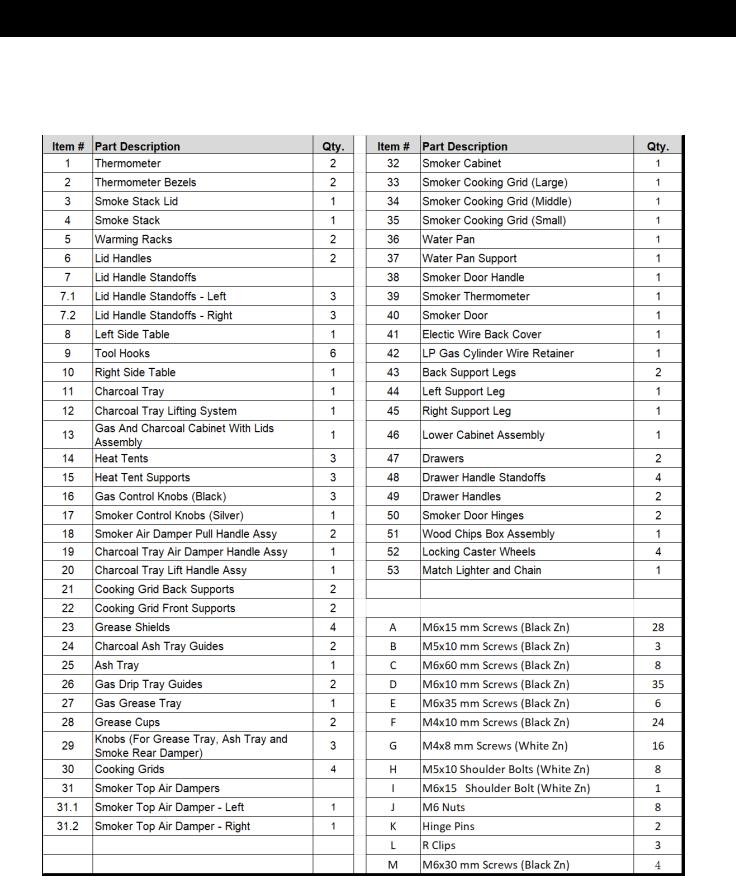
PARTS & SPECS
When you open your Memphis Ultimate Grill, please ensure you have and can identify all the following parts:
NOTE: Numbers preceding parts names throughout this manual refer to the component diagram below.
NOTE: Due to ongoing product development, parts are subject to change without notice. Contact Customer Service if parts are missing when assembling the unit.
7
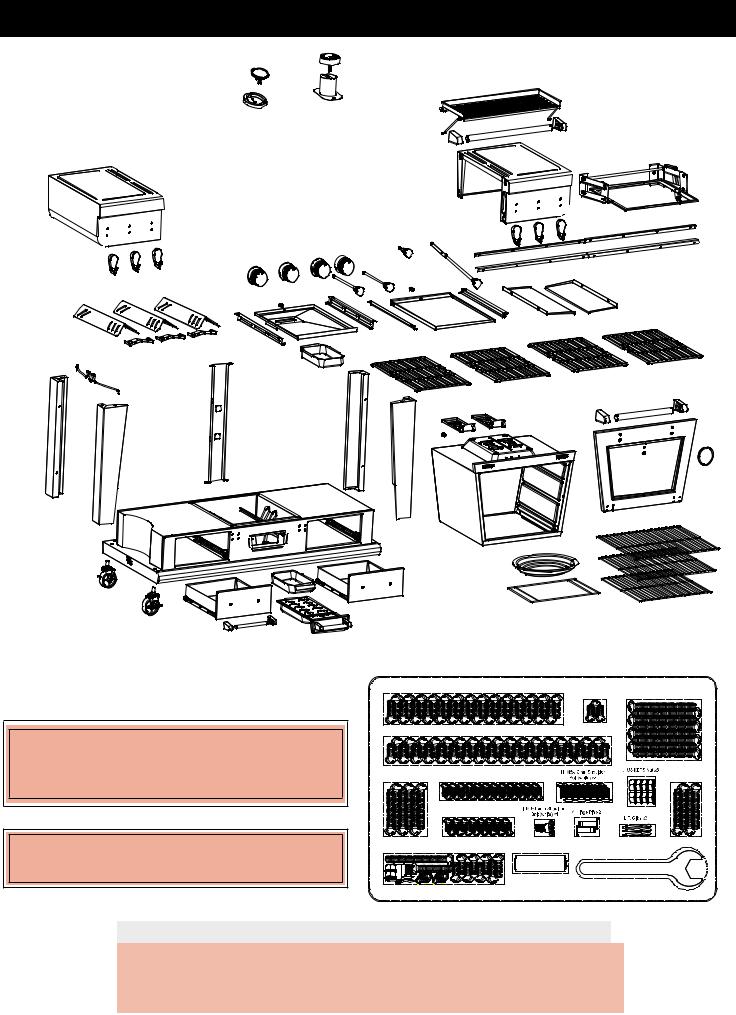
PARTS & SPECS
PB – LP GAS BTU REQUIREMENTS
BTU: 10,000BTU/ BURNER TOTAL: 30,000BTU
PB – ELECTRIC REQUIREMENTS
120V, 13.75AMP, 60HZ, 1650W, 3-PRONG GROUNDED PLUG
|
A M6 x15mm Bolt (black) x 28 |
|
B M5 x 10 Bolt (black) x3 |
C M6x60mm Bolt (black) x8 |
|
|
|
||
|
D M6 x10mm Bolt (black) x 35 |
|
|
|
|
|
|
|
M M6x30mm |
E M6x35mm Bolt (black) x6 |
F M4 x 10 Bolt (black) x24 |
|
|
Bolt (black) x4 |
|
G M4 x 8 Bolt (white) x16 |
|
|
|
Extra Hardware |
AA Battery x1 |
Wheel Wrench x1 |
||
|
|
|
||
PBMEMU1
|
|
|
|
|
|
|
|
|
|
|
|
MODEL |
|
UNIT ASSEMBLED (WxHxD) |
UNIT WEIGHT |
COOKING AREA |
|
TEMP. RANGE |
|||||
|
|
|
1880mm x 1200mm x |
|
|
|
Cubic Cooking: 0.047 m3 /1.65 ft3 |
|
E-Smoker: |
||
PB |
|
|
98. |
kg |
|
38-204°C |
|||||
PBMEMU1 |
|
630mm |
(ELECTRIC SMOKER ONLY) |
|
|||||||
|
|
|
|
/ 100-400°F |
|||||||
|
|
|
|
/ 74” x 47” x 24 3/4” |
/ 215 lb |
TOTAL-11,960cm² / 1,853sq. in. |
|
||||
|
|
|
|
|
|
|
|
|
|||
|
|
|
|
|
|
|
|
|
|
|
|
8

ASSEMBLY PREPARATION
Parts are located throughout the shipping carton, including inside the COMB grill with electric smoker. Inspect the unit, parts, and hardware blister pack after removing from the protective
shipping carton. Before assembly of product, review all parts and reference the parts list. If any part is missing or damaged, do not attempt to assemble. Shipping damage is not covered under warranty. Contact your dealer or Pit Boss Customer Service for parts at 1-877-303-3134 .
IMPORTANT: To ease installation, using two people is helpful when assembling this unit.
Tools required for assembly: screwdriver and wrench. A wrench for the wheels is included.
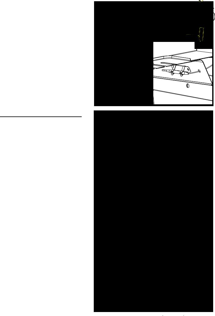
ASSEMBLY INSTRUCTIONS
IMPORTANT: It is advised to read each step entirely before starting assembly on instructions. Do not tighten screws completely until all screws for that step have been installed, or unless otherwise mentioned.
1. MOUNTING THE LEFT FRONT |
Fig.1 |
SUPPORT LEG TO LOWER |
|
CABINET ASSEMBLY |
|
Parts Required:
1 x Lower Cabinet Assembly(#46)
1 x Left Front Support Leg (#44)
2 x M6x60mm Screw (#C)
1 x M4x10mm Screw (#F)
Installation:
• Place a piece of cardboard on the floor to prevent scratching the unit.
• Mount Left Front Support Leg (#44) to the Lower Cabinet Assembly (#46)
Use: 2 x M6x60mm Screws (#C) &
1 x M4x10mm Screw (#F) see Fig.1
-----------#44
M4x10 bolt
9

2. MOUNTING THE RIGHT FRONT SUPPORT LEG TO LOWER CABINET
ASSEMBLY
Parts Required:
1 x Lower Cabinet Assembly (#46)
1 x Right Front Support Leg (#45)
2 x M6x60mm Screw (#C)
1 x M4x10mm Screw (#F)
Installation:
• Mount Right Front Support Leg(#45) to the Lower Cabinet Assembly (#46).
Use: 2 x M6x60mm Screws (#C) &
1 x M4x10mm Screw (#F) see Fig.2
Fig.2
#45 |
------------- |
|
M4x10 bolt
3. MOUNTING THE BACK SUPPORT |
Fig.3 |
LEGS TO LOWER CABINET ASSEMBLY |
|
Parts Required:
1 x Lower Cabinet Assembly (#46)
1 x Right Rear Support Leg (#43)
1 x Left Rear Support Leg (#43)
4 x M6x60mm Screw (#C)
Installation:
• Mount Right Rear Support Leg(#43) and Left Rear Support Leg (#43) to the Lower Cabinet Assembly (#46).
Use: 4 x M6x60mm Screws (#C). see Fig.3
------------
#43 This face (wider) should be facing back side
#43 This face (wider) should be facing back side
---------------
10
4. MOUNTING THE CASTERS TO |
Fig.4 |
BOTTOM TABLE ASSEMBLY |
|
Parts Required:
4 x Caster with Lock (#52)
1 x Lower Cabinet Assembly (#46)
Installation:
• Turn Lower Cabinet Assembly (#46) upside down and mount 4 Caster with Lock
(#52) to Lower Cabinet Assembly (#46) see Fig.4
5. ATTACHING THE LP GAS CYLINDER WIRE RETAINER TO LEFT REAR SUPPORT LEG AND LEFT FRONT SUPPORT LEG
Parts Required:
1 x LP Gas Cylinder Wire Retainer (#42)
1 x Left Rear Support Leg (#43)
1 x Left Front Support Leg (#44)
1 x R Clip (#L)
Installation:
Attach the LP Gas Cylinder Wire Retainer (#42) to the Left Rear Support Leg (#43)
and Left Front Support Leg (#44) Use: R-Clip (#L)
see Fig.5
6. MOUNTING THE KNOB TO THE AIR DAMPER OF SMOKER CABINET ASSEMBLY
Parts Required:
1 x Smoker Cabinet Assembly (#32)
1 x Knob (#29)
1 x M5x10mm Screw (#B)
Installation:
• Mount Knob (#29) to the Air Damper of Smoker Cabinet (#32).
Use: 1 x M5x10mm (#B) see Fig.6
Fig.5
#44 |
------------- |
|
Fig.6
---------
#43
11

7. ATTACHING THE SMOKER CABINET ASSE MBLY TO THE LOWER CABINET
Parts Required:
1 x Smoker Cabinet Assembly (#32)
1 x Lower Cabinet Assembly (#46)
2 x M6x15mm Screw (#A)
2 x M6x35mm Screw (#E)
Installation:
• Attach Smoker Cabinet Assembly (#32) to the Lower Cabinet Assembly(#46). Use: 2 x M6x15mm (#A) and
2 x M6x35mm (#E) see Fig.7
8. SLIDING THE WOOD CHIPS BOX ASSEMBLY INTO THE LOWER CABINET ASSEMBLY
Parts Required:
1 x Wood Chip Box Assembly (#51)
1 X Lower Cabinet Assembly (#46)
Installation:
•Slide Wood Chip Box Assembly (#51) onto the Wood Chip Box support rails of
Lower Cabinet Assembly (#46) see Fig.8
•
Note: When removing the Wood Chip Box from the smoker, lift up on the handle and pull out the Wood Chip Box.
9. MOUNTING THE DRAWER HANDLE AND HANDLE STANDOFF TO THE DRAWER
Parts Required:
2 x Drawer Handles (#49)
4 x Drawer Handle Standoffs (#48)
2 x Drawers (#47)
4 x M6x10mm Screws (#D)
Installation:
• Mount one Drawer Handle (#49) and 2 Drawer Handle Standoff (#48) to the Drawer (#47)
Use: 2 x M6x10mm (#D) see Fig.9
Repeat the same step for other drawer.
Fig.7
M6x15 bolt
M6x35 bolt
Fig.8
Fig.9
#48-1(L) ----- -----#48-2(R)
12

10. SLIDING THE DRAWER ASSEMBLY |
Fig.10 |
INTO THE LOWER CABINET ASSEMBLY |
|
|
Parts Required:
2 x Drawer Assembly (#47,#48 & #49)
1 X Lower Cabinet Assembly (#46)
Installation:
•Slide Drawer Assembly (#47, #48 & #49)
into the Lower Cabinet Assembly (#46)
see Fig.10
11. PLACING THE WATER PAN |
Fig.11 |
SUPPORT INTO THE SMOKER |
|
CABINET ASSEMBLY |
|
Parts Required:
1 x Water Pan Support (#37)
1 X Smoker Cabinet Assembly (#32)
Installation:
•Slide Water Pan Support (#37) into the Smoker Cabinet Assembly (#32)
see Fig.11 & Fig.11.1.


 Fig.11.1
12. PLACING THE WATER PAN INTO |
Fig.12 |
THE SMOKER CABINET ASSEMBLY |
|
Parts Required:
1 x Water Pan (#36)
1 X Smoker Cabinet Assembly (#32)
Installation:
•Slide Water Pan (#36) into the Smoker
Cabinet Assembly (#32) see Fig.12
13

13. SLIDE THREE DIFFERENT SMOKER COOKING GRIDS INTO THE SMOKER CABINET ASSEMBLY
Parts Required:
1 x Smoker Cooking Grid (Large) (#33)
1 x Smoker Cooking Grid (Middle) (#34)
1 x Smoker Cooking Grid (Small) (#35)
1 X Smoker Cabinet Assembly (#32)
Installation:
•Slide Smoker Cooking Grid (Large)(#33), Smoker Cooking Grid (Middle)(#34) and Smoker Cooking Grid (Small)(#35) into the
Smoker Cabinet Assembly (#32) see Fig.13
14. MOUNTING THE SMOKER DOOR HANDLE AND LARGE HANDLE STAND-OFF TO THE SMOKER DOOR
Parts Required:
1 x Smoker Door Handle (#38)
2 x Large Handle Standoffs (#7)
1 x Smoker Door (#40)
4 x M6x35mm Screws (#E)
Installation:
• Mount one Smoker Door Handle (#38) and 2 Large Handle Standoffs (#7) to
the Smoker Door (#40)
Use: 4 x M6x35mm (#E) see Fig.14.1 & Fig.14.2
Note: Slots on both side of Smoker Door Handle must be inserted into the embossed area on inside area of Handle Stand-off as Fig 14.1 shown.
15. INSERTING THERMOMETER INTO
THE SMOKER DOOR ASSEMBLY
Parts Required:
1 X Smoker Thermometer (#39) 1 x
Smoker Door Assembly (#40) Note: The Thermometer is supplied
with one fiber washer and one wing nut.
Installation:
•Insert Smoker Thermometer (#39) probe through the mounting hole in the front of the Smoker Door Assembly (#40). From the inside of the door, place fiber washer and
wing nut onto the mounting thread pole and tighten by hand and do not over tighten. see Fig.15
Fig.13
#33 ---------
#34 --------
#35 ---------
Fig.14.1
#7.1(L) ------
------ #7.2(R)
Fig.14.2
Fig.15
14

16. MOUNTING THE SMOKER DOOR |
Fig.16 |
HINGES TO THE SMOKER DOOR |
|
|
Parts Required:
2 x Smoker Door Hinges (#50)
1 x Smoker Door (#40)
8 x M4x8mm White Zn Screws (#G)
Installation:
• Mount two Smoker Door Hinges (#50) to
the Smoker Door (#40).
Use: 8 x M4x8mm (#G) see Fig. 16
Correct
Direction


 -----------


17. MOUNTING THE SMOKER DOOR WITH HINGE TO THE LOWER CABINET ASSEMBLY
Parts Required:
1 x Smoker Door (#40)
1 x Lower Cabinet Assembly (#46)
8 x M4x8mm White Zn Screws (#G)
Installation:
• Mount Smoker Door (#40) with Hinge assembly to Lower Cabinet Assembly (#46).
Use: 8 x M4x8mm (#G) see Fig.17
18. PREPARATION OF ATTACHING THE GAS AND CHARCOAL CABINET ASSEMBLY ONTO THE CART ASSEMBLY
Parts Required:
1 x Gas and Charcoal Cabinet with Lids Assembly (#13)
1 x Cart Assembly
Installation:
• Carefully put the main chamber on the top of smoker body and then remove the twist tie. Pull out the smoker electric wires and
smoker temperature wire/sensor from the back side of Control panel first, then place the electric wires toward back and place the temperature wire and sensor toward front see Fig.18.1
Attention: Do not pinch or sandwich the electric wires and/or temperature wire sensor during the assembly.
Fig.17
Fig.18.1
 ------ Cart Assembly
Fig.18.2
Twist tie--------------- |
|
|
|
Electric |
|
Temp sensor |
--- |
--- |
------------ |
||
wires |
|||||
|
|||||
----- |
|
|
|
|
15
19. ATTACHING THE TEMPERATURE SENSOR INSIDE THE SMOKER CABINET
Parts Required:
1 x Temperature Sensor
Installation:
•Insert the Smoker Temperature Sensor through the hole on the top of Smoker Cabinet.
Next attach it into the clip which is located inside top area of the Smoker
Cabinet.
see Fig.19.1, Fig.19.2 and Fig.19.3.
20. ATTACHING ELECTRIC WIRES
ONTO TWO CLIPS NEAR THE SMOKER CABINET, ATTACHING THE GAS AND CHARCOAL CABINET ASSEMBLY ONTO THE CART ASSEMBLY
Parts Required:
1 x Electric Wires
1 x Electric Wires Male Socket (end of the Electric Wires)
1 x Electric Wires Female Socket
1 x Gas and Charcoal Cabinet with Lids Assembly (#13)
1 x Cart Assembly
8 x M6x15mm Screw (#A)
4 x M6x10mm Screw (#D)
Installation:
Note: The Main Chamber must be lined up to the Trolley.
• Carefully open the lids, attach Gas and Charcoal Cabinet Assembly (#13) to the
Cart Assembly
Use: 8pcs M6x15mm screws (#A) and 4 x M6x10mm Screw (#D)
see Fig.20.1, Fig.20.1a, Fig.20.1b
Note: Fix 4pcs M6x10mm screws (#D) on inside first, then fix the other 8pcs M6x15mm screw (#A) later. Regulator can be taken out at this stage for later assembly.
• Attach the Electric Wires onto two clips near the Smoker Cabinet from the lower area of charcoal grill side and then attach the Electric Wires Male Socket (end of the Electric Wires) to the Female Socket which is located on the back of Bottom Table See Fig 20.2 and Fig.20.3
Fig.19.1 |
|
|
|
|
|
|
|
Fig.19.3 |
------------------------- |
|
|
|
|
|
|
|
Fig.19.2 |
|
|
|
|
------------- |
|
|
|
|
Temperature sensor |
|
|
|
|
||||
|
|
|
|
|
|
|
|
|
|
|
|
|
Inside top area of |
|
|
||
|
|
|
|
Electric Smoker |
|
|
||
Fig.20.1 |
|
|
|
|
|
|
|
View |
|
|
|
---- |
|
|
|
|
hole |
|
|
|
|
|
|
|
for leg |
|
Regulator |
|
|
|
|
|
|
||
|
|
|
|
|
|
screws |
||
----- |
|
|
|
|
|
|||
|
|
M6x10mm |
|
|
||||
|
|
------------ |
|
|
------ |
|||
|
|
|
|
--------- |
|
|
||
|
|
|
|
|
|
|
||
|
|
|
|
|
|
|
|
Fig.20.1b |
Fig.20.1a |
|
|
|
|
|
|
|
|
|
|
|
|
|
|
|
M6x15mm |
|
|
|
|
------ |
|
|
|
--------- |
|
-- |
|
|
|
|
|
|
|
|
-- |
|
|
|
|
|
|
|
|
|
|
|
|
|
|
|
|
|
|
|
|
|
|
|
|
------------------ |
|
----- |
|
M6x15mm |
|
|
|
|
|
|
|
|
|
|
|
|
|
||
|
--------------------- |
|
|
|
View |
hole |
for leg |
|
View hole for leg |
|
|
||||||
screws assembly |
|
|
screws assembly |
|||||
Fig.20.2 |
|
|
|
|
|
|
|
|
|
|
Electric |
--------------- |
|
|
|||
|
|
|
|
|
|
|
||
|
|
Wires |
|
|
|
|
|
|
Fig.20.3 |
|
|
|
|
|
|
|
|
|
|
Male Socket |
------ |
------- |
Female |
|
||
|
|
|
|
Socket |
|
|||
|
|
|
|
|
|
|||
|
|
|
|
|
|
|
|
|
16 |
|
|
|
|
|
|
|
|

21. ATTACH THE ELECTRICAL
BACK COVER TO THE BACK SIDE OF SMOKER CART ASSEMBLY
Parts Required:
1 x Electric Wires Back Cover (#41)
1 x Cart Assembly
2 x M6x15mm Screw (#A)
Installation:
•Unscrew two M6x15mm screws (factory pre-assembled) from Bottom Table. Attach Electrical Back Cover (#41) to the back side of Smoker Cart Assembly
•Use: 2pcs M6x15mm screws (#A) see Fig.21
Note: Assemble the screws on top side first and then assemble the bottom screws later.
22. MOUNTING THE SMOKER TOP AIR DAMPERS TO THE TOP OF SMOKER CABINET ASSEMBLY
Parts Required:
2 x Smoker Top Air Dampers (#31)
1 x Smoker Cabinet Assembly (#32)
8 x M5x10mm Shoulder Bolts (#H)
Installation:
•Mount Smoker Top Air Dampers (#31) to the Smoker Cabinet Assembly.
Use: 8pcs M5x10 Shoulder bolts (#IH)
see Fig.22
•Note: The Smoker Top Air Dampers have identification label by left and right. Please
install to corresponding position. Make sure the shoulder to insert onto the slots of air dampers and the air dampers can be moved smoothly.
23. ATTACHING THE SMOKER AIR DAMPERS PULL HANDLE ASSEMBLY TO THE SMOKER TOP AIR DAMPERS
Parts Required:
2 x Smoker Air Damper Pull Handle
Assembly (#18)
2 x Smoker Top Air Dampers (#31)
Installation:
•Attach two Smoker Air Damper Pull Handle Assembly (#18) to two Smoker Top Air
Dampers (#31) see Fig.23
Fig.21
Fig.22
Fig.23
#31.1 (L) |
|
------------- |
#31.2(R) |
|
------------- |
17
 Loading...