


MODEL : PB440TGR1 PART : 72444
RANCH
HAND
WOOD PELLET GRILL & SMOKER
IMPORTANT, READ CAREFULLY, RETAIN FOR FUTURE REFERENCE. MANUAL MUST BE READ BEFORE OPERATING!
FOR OUTDOOR USE ONLY.
NOT FOR COMMERCIAL USE.
PATIO
POSITION
TAILGATING &
TRAVEL POSITION
ASSEMBLY AND OPERATION INSTRUCTIONS
WARNING: Please read the entire manual before installation and use of this electric, pellet fuel burning appliance. Failure to follow these instructions could result in property damage, bodily injury or even death.
Contact local building or fire officials about restrictions and installation inspection requirements in your area.
RECIPES |
INCLUDED |
|
|
||
INBACK |
OFMANUAL |
|
|
|
|

SAFETY INFORMATION
MAJOR CAUSES OF APPLIANCE FIRES ARE A RESULT OF POOR MAINTENANCE AND A FAILURE TO MAINTAIN REQUIRED CLEARANCE TO COMBUSTIBLE MATERIALS. IT IS OF UTMOST IMPORTANCE THAT THIS PRODUCT BE USED ONLY IN ACCORDANCE TO THE FOLLOWING INSTRUCTIONS.
Please read and understand this entire manual before attempting to assemble, operate or install the product. This will ensure you receive the most enjoyable and trouble-free operation of your new wood pellet grill. We also advise you retain this manual for future reference.
DANGERS AND WARNINGS
You must contact your local home association, building or fire officials, or authority having jurisdiction, to obtain the necessary permits, mission or information on any installation restrictions, such as any grill being installed on a combustible surface, inspection requirements or even ability to use, in your area.
1.A minimum clearance of 305mm (12 inches) from combustible constructions to the sides of the grill, and 305mm (12 inches) from the back of the grill to combustible constructions must be maintained. Do not use this appliance indoors or in an enclosed, unventilated area. This wood pellet appliance must not be placed under overhead combustible ceiling or overhang. Keep your grill in an area clear and free from combustible materials, gasoline and other flammable vapors and liquids.
Should a grease fire occur, turn the grill OFF and leave the lid closed until the fire is out. Do not unplug the power cord. Do not throw water on the unit. Do not try to smother the fire. Use of an all-class (class ABC) approved fire extinguisher is valuable to keep on site. If an uncontrolled fire does occur, call the Fire Department.
2.Keep electrical supply cords and the fuel away from heated surfaces. Do not use your grill in the rain or around any water source.
3.After a period of storage, or non-use, check the burn grate for obstructions, the hopper for foreign objects, and any air blockage around the fan intake or rear barrel exhaust holes. Clean before use. Regular care and maintenance is required to prolong the lifespan of your unit. If the grill is stored outside during the rainy season or seasons of high humidity, care should be taken to insure that water does not get into the hopper. When wet or exposed to high humidity, wood pellets will expand greatly, decompose, and may jam the feed system. Always disconnect the power, before performing any service or maintenance.
Do not transport your grill while in use or while the grill is hot. Ensure the fire is completely out and that the grill is completely cool to the touch before moving.
4.It is recommended to use heat-resistant barbecue mitts or gloves when operating the grill. Do not use accessories not specified for use with this appliance. Do not put a barbecue cover or anything flammable in the storage space area under the barbecue.
5.To prevent fingers, clothing or other objects from coming in contact with the auger feed system, the appliance is equipped with a metal safety screen, mounted to the interior of the hopper. This screen must not be removed unless directed by Customer Service or an authorized dealer.
This appliance is not recommended for children, persons with reduced physical, sensory or mental capabilities, or lack of experience and knowledge, unless they are under direct supervision or instruction by a person responsible for their safety.
6.Parts of the barbecue may be very hot, and serious injury may occur. Keep young children and pets away while in use.
7.Do not enlarge igniter holes or burn pots. Failure to follow this warning could lead to a fire hazard and bodily harm and will void your warranty.
2

DISPOSAL OF ASHES
Ashes should be placed in a metal container with a tight-fitting lid. The closed container of ashes should be placed on a noncombustible floor or on the ground, well away from all combustible materials, pending final disposal. When ashes are disposed by burial in soil, or otherwise locally dispersed, they should be retained in a closed container until all cinders have thoroughly cooled.
WOOD PELLET FUEL
This pellet cooking appliance is designed and approved for pelletized, all natural, wood fuel only. Any other type of fuel burned in this appliance will void the warranty and safety listing. You must only use all natural wood pellets, designed for burning in pellet barbecue grills. Do not use fuel with additives.
Do not use spirit, petrol, gasoline, lighter-fluid or kerosene for lighting or refreshing a fire in your grill.
At this time of printing, there is no industry standard for barbecue wood pellets, although most pellet mills use the same standards to make wood pellets for domestic use. Further information, can be found at www.pelletheat.org or the Pellet Fuel Institute.
Contact your local dealer on the quality of pellets in your area, and for information on brand quality. As there is no control over the quality of pellets used, we assume no responsibility to damage caused by poor quality of fuel.
CREOSOTE
Creosote, or soot, is a tar-like substance. When burning, it produces black smoke with a residue which is also black in color. Soot or creosote is formed when the appliance is operated incorrectly, such as: incorrect position of the burn grate, blockage of the combustion fan, failure to clean and maintain the burn area, or poor air-to-fuel combustion.
It is dangerous to operate this appliance should the flame become dark, sooty, or if the burn pot is overfilled with pellets. When ignited, this creosote makes an extremely hot and uncontrolled fire, similar to a grease fire. Should this happen, turn the unit OFF, let it cool completely, then inspect for maintenance and cleaning. It commonly accumulates along exhaust areas.
If creosote has formed within the unit; allow the unit to warm up at a low temperature, turn off the appliance, then wipe away any formation with a hand towel. Similar to tar, it is much easier to clean when warm, as it becomes liquid.
CARBON MONOXIDE (“the silent killer”)
Carbon monoxide is a colorless, odorless, tasteless gas produced by burning gas, wood, propane, charcoal or other fuel. Carbon monoxide reduces the blood’s ability to carry oxygen. Low blood oxygen levels can result in headaches, dizziness, weakness, nausea, vomiting, sleepiness, confusion, loss of consciousness or death.
See a doctor if you or others develop cold or flu-like symptoms while cooking or in the vicinity of the appliance. Carbon monoxide poisoning, which can easily be mistaken for a cold or flu, is often detected too late.
Alcohol consumption and drug use increase the effects of carbon monoxide poisoning.
Carbon monoxide is especially toxic to mother and child during pregnancy, infants, the elderly, smokers, and people with blood or circulatory system problems, such as anemia, or heart disease.
SAFETY LISTING
In accordance with the procedures and specifications listed in the UL Subject 2728-2009 "pellet fuel cooking appliances" and ULC/ORD C272 and Canadian CSA C22.2 #3 "for electrical features of fuel burning equipment." Pit Boss Grills pellet cooking appliances have been independently tested and listed by Intertek (an accredited testing laboratory) to ETL, UL, ULC and CSA standards.
3

COPYRIGHT NOTICE
Copyright 2017. All right reserved. No part of this manual may be copied, transmitted, transcribed, stored in a retrieval system, in any form or by any means without expressed written permission of,
Dansons Inc.
3411 North 5th Avenue, Suite 500, Phoenix, AZ, USA 85013 sales@pitboss-grills.com | service@pitboss-grills.com www.pitboss-grills.com
Toll-Free: 1-877-303-3134, Fax: 1-877-303-3135
4

TABLE OF CONTENTS
Safety Information ........................................................... |
2 |
Parts & Specs...................................................................... |
6 |
Assembly Preparation...................................................... |
7 |
Assembly Instructions |
|
Expanding The Cart Base............................................................ |
7 |
Mounting The Wheels To The Legs .......................................... |
7 |
Securing The Lid Stopper ........................................................... |
8 |
Installing The Hopper To The Barrel ........................................ |
8 |
Assembling The Lid Handle........................................................ |
8 |
Installing the Thermometer....................................................... |
9 |
Placing The Grease Bucket.......................................................... |
9 |
Assembling The Side Shelf.......................................................... |
9 |
Mounting The Side Shelf............................................................. |
9 |
Installing The Cooking Components ..................................... |
10 |
Connecting To A Power Source................................................ |
10 |
Operating Instructions |
|
Grill Environment......................................................................... |
11 |
Grill Temperature Ranges........................................................... |
12 |
Understanding The Probes ....................................................... |
12 |
Tailgating and Travel Position................................................... |
13 |
Understanding The Control Board.......................................... |
14 |
Hopper Priming Procedure...................................................... |
14 |
First Use – Grill Burn-Off........................................................... |
15 |
Preheating..................................................................................... |
15 |
Automatic Start-Up Procedure................................................ |
15 |
Manual Start-Up Procedure..................................................... |
16 |
Shutting Off Your Grill............................................................... |
16 |
Care & Maintenance......................................................... |
16 |
Using Wood Pellet Fuel.................................................. |
18 |
Cooking Guidelines.......................................................... |
18 |
Tips & Techniques............................................................ |
20 |
Troubleshooting ............................................................... |
21 |
Electrical Wire Diagram.................................................. |
23 |
Replacement Parts |
|
Grill Replacement Parts ............................................................ |
24 |
Hopper Replacement Parts...................................................... |
25 |
Warranty |
|
Conditions..................................................................................... |
25 |
Exceptions.................................................................................... |
26 |
Ordering Replacement Parts.................................................... |
26 |
Contact Customer Service......................................................... |
26 |
Warranty Service ........................................................................ |
26 |
Accessories Sold Separately.......................................... |
27 |
Recipes............................................................................... |
28 |
5

PARTS & SPECS
Part# Description
1 Porcelain-Coated Steel Upper Cooking Rack
2Porcelain-Coated Steel Cooking Grids (x2)
3Thermometer Kit
4Lid Stopper
5Power Cord Bracket
6Probe Wire Casing
7Flame Broiler Slider
8Flame Broiler Main Plate
9Hopper Assembly, Drop Chute Plate and Screw
10 Lid Handle Bezel (x2)
11 Lid Handle (x2)
12 Main Barrel
13 Grease Bucket
14 Wheel (x2)
15 Bottom Shelf
16 Side Shelf
17 Tool Hook (x3)
18 Bottle Opener
19 Side Shelf Handle
A Screw (x4) B Washer (x4)
C Locking Washer (x4)
D Wheel Cotter Pin (x2) E Wheel Washer (x2)
F Wheel Axle Pin (x2)
NOTE: Due to ongoing product development, parts are subject to change without notice. Contact Customer Service if parts are missing when assembling the unit.
PB – ELECTRIC REQUIREMENTS
110-120V, 3.3AMP, 60HZ, 275W, 3-PRONG GROUNDED PLUG
2
5
6 7
9
10
11
12
13
14
15
20
A  D
D  B
B  E
E  C
C  F
F
1
3
4
8
16
19 18 17
MODEL |
UNIT ASSEMBLED (WxHxD) |
UNIT WEIGHT |
COOKING AREA |
TEMP. RANGE |
DIGITAL FEATURES |
||
PB |
|
1,066mm x 1029mm x 554mm |
40.1 kg |
Main - 2,200 cm² / 341 sq. in. |
82-260°C |
Ten temperature |
|
PB440TGR1 |
presets, start-up cycle, |
||||||
/ 42” x 40 ½” x 21 ¾” |
/ 88.4 lb |
TOTAL - 2,200 cm² / 341 sq. in. |
/ 180-500°F |
||||
|
|
electric igniter |
|||||
|
|
|
|
|
|
||
|
|
|
|
|
|
|
|
6

ASSEMBLY PREPARATION
Parts are located throughout the shipping carton, including underneath the grill. Inspect the grill, parts, and hardware blister pack after removing from the protective shipping carton. Before assembly of product, review all parts and reference the parts list. If any part is missing or damaged, do not attempt to assemble. Shipping damage is not covered under warranty. Contact your dealer or Pit Boss Customer Service for parts.
IMPORTANT: To ease installation, using two people is helpful (but not necessary) when assembling this unit.
Tools required for assembly: screwdriver and level. Tools not included.
ASSEMBLY INSTRUCTIONS
NOTE: For all of the following steps, do not tighten any screws completely until all screws for that step have been installed. Once all screws have been installed, then tighten them securely.
1. EXPANDING THE CART BASE
Parts Required:
1 x Main Barrel (#12)
Installation:
•Place a piece of cardboard on the floor to prevent scratching the unit. Lay the main barrel on its back on the cardboard, lid facing upward. Open the right side of the cart first by pressing down firmly on the right folding bar (A), then swing open the right side cart legs. Once the legs are extended, the right folding bar will spring back into the locked position. Ensure the diagonal support bar (B) extends completely and locks into a brace position, then tighten the two folding bar knobs (C). Note illustration 1A.
•Next, open the left side of the cart by press down firmly on the left folding bar (to unlock) and pull out the left side cart legs until extended. Once open, the left folding bar will spring back into the locked position. Note illustration 1B.
IMPORTANT: The folding bar on each pair of cart legs should always be in a locking position (raised up) when the grill is in use.
•Finally, unfold the bottom shelf, and expand into a flat surface. Secure the right side by bracing into the holes on the right side of the cart. Note illustration 1C.
2.MOUNTING THE WHEELS TO THE LEGS
Parts Required:
2 |
x |
Wheel (#14) |
2 |
x Wheel Cotter Pin (xD) |
|
2 |
x |
Wheel Washer (xE) |
2 |
x Wheel Axle Pin (xF) |
|
Installation:
•Attach the wheel to the leg by inserting the wheel axle pin through
1A |
|
|
C |
B |
A |
|
|
|
C |
1B |
|
1C |
|
2 |
|
7
the wheel, then the leg hole, wheel washer, and finally secure using the wheel cotter pin. Note illustration for order. Repeat installation for the other wheel. Once installed, from the rear of the grill, lift the grill into an upright position.
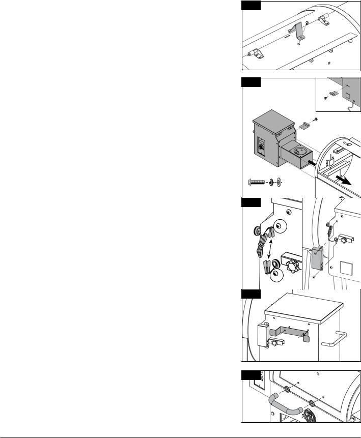
3. SECURING THE LID STOPPER
Parts Required:
1 |
x Lid Stopper (#4) |
Installation:
•Secure the lid stopper onto the top of the main barrel using the pre-installed screw on the top of the main barrel.
4.INSTALLING THE HOPPER TO THE BARREL
Parts Required:
1 |
x Hopper Assembly, Drop Chute Plate and Screw (#9) |
|
1 |
x Probe Wire Casing (#6) |
|
4 |
x |
Screw (#A) |
4 |
x |
Locking Washer (#B) |
4 |
x |
Washer (#C) |
1 |
x Power Cord Bracket (#5) |
|
Installation:
•Secure the drop chute screw to the drop chute plate, and insert into the horizontal slit on the rear side of the hopper.
•Align the burn pot end of the hopper assembly into the opening on the end of the main barrel. Insert only half-way, then carefully slide the hopper assembly completely into the opening on the end of the main barrel. Secure the hopper assembly to the main barrel, from the inside of the barrel, using four screws, locking washers, and washers. Take care not to over-tighten to avoid stripping the screws. Note illustration 4A.
•On the rear side of the hopper, connect the silver grill probe temperature wires – extruding from the main barrel – to the wire connections from the rear of the hopper assembly. Remove the two pre-mounted screws. Tuck the excess wire into the probe wire casing, placing the wire distinctly in the divet along the edge to avoid pinching. Next, secure the probe wire casing to the hopper using the two screws previously removed. Note illustration 4B.
IMPORTANT: Ensure the grill probe temperature wires do not get pinched. Damage to the grill probe temperatures wires may result in incorrect readings, or inability to funtion.
•Secure the power cord bracket using the two screws pre-installed on the rear side of the hopper, above the drop chute plate. Note illustration 4C.
5.ASSEMBLING THE LID HANDLE
Parts Required:
1x Lid Handle (#11)
2x Lid Handle Bezel (#10)
3 |
|
|
4A |
|
|
|
|
REAR VIEW |
A |
C |
B |
4B |
|
|
4C |
|
|
5A |
|
|
8

Installation:
•Remove the pre-installed screws from the lid handle. From inside the barrel lid, insert one screw to protrude to the outside. Add a bezel on the screw, then hand-tighten the screw (from the inside) into the lid handle. Repeat for the other side.
6.INSTALLING THE THERMOMETER
Parts Required:
1 |
x Thermometer Kit (#3) |
Installation:
•Remove the pre-installed nut from the thermometer. Insert the thermometer into the hole provided on the top of the lid on the main barrel, then secure by re-installing the nut from the inside. Rotate the thermometer so the text is level and upright.
NOTE: If rotation is askew, this will result in incorrect readings.
7. PLACING THE GREASE BUCKET
Parts Required:
1 |
x Grease Bucket (#13) |
Installation:
•Place the grease bucket on the spout hook on the end of the main barrel. Ensure it is level to avoid grease spills.
8.ASSEMBLING THE SIDE SHELF
Parts Required:
1 |
x |
Side Shelf (#16) |
3 |
x |
Tool Hook (#17) |
1 |
x Side Shelf Handle (#19) |
|
1 |
x |
Bottle Opener (#18) |
Installation:
•Turn the side shelf upside down. On the edge of the side shelf with three holes, install the tool hooks into each hole along the edge. Tool hooks will secure to the self-clinching nut that is pre-mounted on the inside.
•Next, remove the pre-mounted screws from the side shelf handle. On the short side with two holes, hand-tighten the screw (from the inside) into the handle. Repeat for the other end of the handle. Note illustration 8A.
•Last, remove the two pre-mounted screws for the bottle opener, and re-install on the corner of the side shelf. Note illustration 8B.
9.MOUNTING THE SIDE SHELF
Installation:
•Remove the four pre-mounted screws from the side of the main barrel.
•From underneath, secure the side shelf to the side panel of the main barrel using the four screws previously removed.
6
7
8A
8B
9
9
NOTE: Do not tighten any screws completely until all screws have been installed. Once all screws are installed, then tighten securely.
IMPORTANT: Avoid using the side shelves to move or lift the grill. The weight of the unit will cause the side shelf to break, which is not covered by warranty.
10. INSTALLING THE COOKING COMPONENTS
Parts Required:
2 |
x |
Cooking Grids (#2) |
1 |
x Upper Cooking Rack (#1) |
|
1 |
x Flame Broiler Main Plate (#8) |
|
1 |
x |
Flame Broiler Slider (#7) |
Installation:
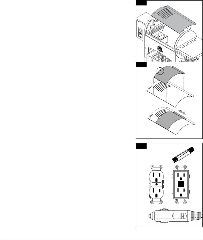
•Insert the flame broiler main plate into the main grill. Rest the flame broiler main plate on the built-in ledge (on the inside right) of the main grill that directs grease towards the grease bucket. Slide the entire piece to the left side, and the two slots on the flame broiler main plate will fit into the rounded ledge above the burn pot. It will sit slightly at a downward angle. Note illustration 10A.
NOTE: If the main plate is on the base of the barrel, it is installed incorrectly.
•Place the flame broiler slider on top of the flame broiler main plate, covering the slotted openings. Ensure the raised tab is on the left, to easily adjust for direct or indirect flame when cooking. Note illustration 10B.
NOTE: When the flame broiler slider is open, and direct flame is used while cooking, do not leave the grill unattended for any period of time.
•Place the cooking grids, side-by-side, on the grid ledge inside the main grill. Place the upper cooking rack on the upper ledge inside the main grill. The cooking rack will lock into place.
•The unit is now completely assembled.
NOTE: To maintain the searing and grilling performance of your cooking grids, regular care and maintenance Is required.
11. CONNECTING TO A POWER SOURCE
•STANDARD OUTLET
This appliance requires 110 volt, 60hz, 275w, 5 amp service. It must be a 3-prong grounded plug. Ensure grounded end is not broken off before use. The control uses a 5 amp, 120 volt, fast-blow fuse to protect the board from the igniter.
•GFCI OUTLETS
This appliance will work on most GFCI outlets, with a recommended size of 15 amp service. If your GFCI outlet is highly sensitive to power surges, it will likely trip during the start-up phase of operation. During the start-up phase, the igniter draws 200-700 watts of electricity which can be too much power for a GFCI outlet to handle. The quality of the GFCI does not matter, but rather the sensitivity; each time it trips, it increases in sensitivity. If the GFCI keeps tripping, replace the outlet or change to a non-GFCI outlet.
10A
10B
11
FAST-BLOW FUSE, 


 5 AMP
5 AMP 
10
 Loading...