


MODEL : PBV2G1
PART : 77425
RED ROCK
GAS VERTICAL SMOKER (2-SERIES)
SAVE THESE INSTRUCTIONS! MANUAL MUST BE READ BEFORE OPERATING!
CONFORMS TO: ANS Z21.89-2013/ CSA 1.18-2013 OUTDOOR COOKING SPECIALTY GAS APPLIANCES
ASSEMBLY AND OPERATION INSTRUCTIONS
WARNING: Please read the entire manual before installation and use of this electric, pellet fuel burning appliance. Failure to follow these instructions could result in property damage, bodily injury or even death.
Contact local building or fire officials about restrictions and installation inspection requirements in your area.
RECIPES |
INCLUDED |
|
|
||
INBACK |
OFMANUAL |
|
|
|
|
 DANGER
IF YOU SMELL GAS:
1.SHUT OFF GAS TO THE APPLIANCE
2.EXTINGUISH ANY OPEN FLAME
3.OPEN LID
4.IF ODOR CONTINUES, KEEP AWAY FROM THE APPLIANCE AND IMMEDIATELY CALL YOUR
GAS SUPPLIER OR YOUR FIRE DEPARTMENT.
5. FAILURE TO FOLLOW THESE INSTRUCTIONS COULD RESULT IN FIRE OR EXPLOSION WHICH COULD CAUSE PROPERTY DAMAGE, PERSONAL INJURY OR DEATH.
 DANGER
1.Never operate this appliance unattended.
2.If the fire should occur, keep away from the appliance and immediately call fire department. Do
not attempt to extinguish an oil or grease fire with water.
3. Failure to follow these instructions could result in fire, explosion or burn hazard which could cause property damage, personal injury or death.
 GAS SMOKER GENERAL WARNINGS
This instruction manual contains important information necessary for the proper assembly and safe use of the appliance. Read and follow all warnings and instructions before assembling and using the appliance. Follow all warnings and instructions whenusing the appliance.
1 Never use or store gasoline, lighter fluid, paint thinner, or other flammable vapors and liquids or combustible materials in or near your smoker.
2 Never use charcoal, lava rocks or wood briquets in a gas smoker. Flavoring chips must be contained in a metal smoking box to contain ash and prevent fires.
3 Ensure flames come out of all burner ports at each use. Spiders and insects like to build nests in burner tubes. Blocked burner tubes can prevent gas flow to the burners and could result in a burner tube fire or fire
beneath the smoker.
4Position your smoker outdoors on a non-combustible level surface in a well ventilated location, a safe distance 10 ft. (3.1 m) from combustible materials, buildings and overhangs.
5Maintain a minimum clearance of 36 inches (91 cm) between all sides of smoker, deck railings, walls or other combustible material. Not adhering to these clearances may prevent proper ventilation and can increase the risk of a fire and/or property damage, which could also result in personal injury. DO NOT use smoker under overhead
unprotected combustible construction.
6 DO NOT leave the smoker unattended while ON or in use.
7 DO NOT use or install this smoker in or on a recreational vehicle and/or boat.
8DO NOT allow grease or hot drippings to fall on hose and regulator assembly. If this occurs, turn gas supply OFF at once. Empty grease tray/cup and clean the hose and regulator assembly and inspect for damage before use.
9 FOR OUTDOOR USE ONLY. DO NOT operate indoors or in an enclosed area such as a garage, shed or breezeway.
10Keep children and pets away from hot smoker. DO NOT allow children to use or play near this smoker.
11DO NOT use water on a grease fire. Closing the lid to extinguish a grease fire is not possible.
12DO NOT allow the gas hose to come in contact with hot surfaces. Redirect the gas hose if necessary. 16 DO NOT block ventilation areas in sides, back or cart compartment of smoker.
13Never check for leaks using a match or open flame.
14DO NOT store items in cart that can catch fire or damage your smoker (such as swimming pool supplies/ chemicals,tablecloth,woodchips).
3
LP Gas Cylinder Installation
 WARNINGS AND SPECIFICATIONS
•Only connect this smoker to a Type 1 cylinder valve. The Type 1 valve can be identified with the large external threads on the valve outlet.
•Do NOT connect to a propane cylinder otherthana 20 lb. (9.1 kg) capacity.
•Do NOT connect to a cylinder that uses any other type of valve connection device.
•Inspect the propane tank valve rubber seal for cracks, wear or deterioration prior to use. A damaged rubber seal can cause a gas leak, possibly resulting in an explosion, fire or severe bodily harm.
•Turn off the cylinder valve when your smoker is not in use.
•Handle the tank with care.
•Always secure the cylinder in an upright position.
•Never connect an unregulated LP gas cylinder to your smoker.
•DO NOT expose LP gas cylinders to excessive heat or ignition sources.
•DO NOT store a spare LP gas cylinder under or near your smoker.
•Never fill an LP cylinder beyond 80% full.
•If the instructions above are not followed exactly, a fire causing death or serious injury may occur.
•Read and follow all warnings and instructions that are on the cylinder and that accompany this product.
 DANGER
•DO NOT store a spare LP gas cylinder (full or empty) under or near your smoker. This could cause excess pressure to be expelled through the vapor relief valve resulting in fire, explosion, or severe personal injury, including death.
•Propane gas is heavier than air and will collect in low areas. Proper ventilation is extremely important. Keep the ventilation opening(s) of the LP gas cylinder enclosure free and clear from obstructions and debris.
•DO NOT insert any foreign objects into the cylinder valve outlet as this could damage the rubber seal. Do not use propane tank with a damaged rubber seal. A damaged rubber seal can cause a gas leak, possibly resulting in explosion, fire, severe bodily harm, or death. Inspect rubber seal for cracks, wear or deterioration prior to use.
•Always keep cylinder (tank) in upright position during use, transit or storage.
Hose & Regulator Installation
 WARNINGS AND SPECIFICATIONS
•DO NOT attempt to connect smoker, as purchased for LP (propane) gas, to any other fuel supply source such as a natural gas line.
•Do not use any other pressure regulator/hose assembly other than the one supplied with your smoker. Replacement pressure regulator/hose assembly must be part No 601-B, KR-106,RJ-A3,which can be obtained by contacting PitBosscustomer service at 1-877-303-3134.
•Do not attempt to adjust or repair a regulator. The regulator is designed to operate at a maximum output pressure of 11 inches of water column (2.74 kPa).
•Ensure the tank valve is closed prior to connecting the LP gas cylinder to your smoker. Turn the valve knob
clockwise to properly close the valve. Read and follow all instructions and warnings on the supply hose
29
safety tags. Read and follow all warnings in this manual concerning the safe use of LP gas cylinders and the hose and regulator before connecting cylinder to smoker. Read and follow all warnings on the LP cylinder.
4

COPYRIGHT NOTICE
Copyright 2017. All right reserved. No part of this manual may be copied, transmitted, transcribed, stored in a retrieval system, in any form or by any means without expressed written permission of,
Dansons Inc.
3411 North 5th Avenue, Suite 500, Phoenix, AZ, USA 85013 sales@pitboss-grills.com | service@pitboss-grills.com www.pitboss-grills.com
Toll-Free: 1-877-303-3134, Fax: 1-877-303-3135
5

TABLE OF CONTENTS
Safety Information ........................................................... |
3 |
Parts & Specs...................................................................... |
7 |
Assembly Preparation...................................................... |
9 |
Assembly Instructions |
|
Mounting The Legs to Lower Cabinet Assembly .................. |
9 |
Mounting Front Legs To Lower Cabinet With Control |
|
Panel Assembly................................................................. |
10 |
Mounting Back Support Tube.................................................. |
10 |
Mounting Support Panels to Legs .......................................... |
11 |
Mounting Burner Chamber Assembly..................................... |
11 |
Mounting Dampers to Upper Cabinet Assembly.................. |
12 |
Mounting Back Handle............................................................... |
12 |
Mounting Upper Cabinet To Lower Cabinet Assembly ...... |
12 |
Assembly Cooking Grid Supports............................................. |
13 |
Placing Water Pan, Water Pan Support, Cooking Grids....... |
13 |
Mounting Door Grease Shield.................................................. |
13 |
Attaching Door Assembly......................................................... |
14 |
Inserting Heat Indicator Into Door Assembly...................... |
14 |
Mounting Door Latch Assembly.............................................. |
14 |
Mounting Door Handle.............................................................. |
15 |
Attaching Gas Cylinder Retainer Bracket............................... |
15 |
Inserting Wood Chips Box.......................................................... |
15 |
Placing Control Knob Onto Valve Stem ................................ |
16 |
Sliding Grease Tray Into The Control Panel .......................... |
16 |
Looping Zip-tie Onto Front Leg 16 |
|
Gas Cylinder (Tank) Instructions................................... |
18 |
Operating Instructions |
|
Quick-Start Lighting................................................................... |
19 |
Leak Testing................................................................................. |
21 |
Seasoning Your Smoker............................................................. |
22 |
How To Use The Wood Chip Tray............................................. |
22 |
Adding Water............................................................................... |
23 |
Igniter Lighting Procedure........................................................ |
23 |
Match Lighting Prodedure........................................................ |
23 |
Damper Adjustments................................................................. |
23 |
Cooking Instructions.................................................................. |
24 |
Tips & Techniques............................................................ |
25 |
Care & Maintenance........................................................ |
26 |
Cooking Guidelines.......................................................... |
27 |
Troubleshooting .............................................................. |
28 |
Accessories Sold Separately.......................................... |
30 |
Replacement Parts........................................................... |
31 |
Warranty |
|
Conditions..................................................................................... |
33 |
Exceptions.................................................................................... |
33 |
Ordering Replacement Parts.................................................... |
34 |
Contact Customer Service......................................................... |
34 |
Warranty Service ........................................................................ |
34 |
Recipes............................................................................... |
35 |
6
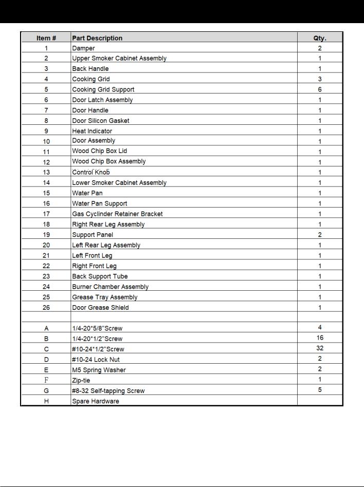
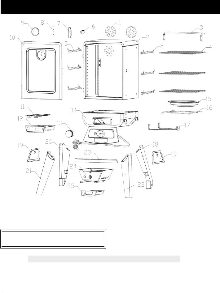
PARTS & SPECS
NOTE: Due to ongoing product development, parts are subject to change without notice. Contact Customer Service if parts are missing when assembling the unit.
7
PARTS & SPECS
PB–BTURATINGREQUIREMENTS
TOTAL:12,500BTU
MODEL |
UNIT ASSEMBLED (WxHxD) |
UNIT WEIGHT |
COOKING AREA |
TEMP. RANGE |
|
PB |
PBV2G1 |
790mmx1030mmx540mm |
21.kg |
CubicCooking:0.06m3 /2.1ft3 |
38-187°C |
|
|
/31”x40”x21” |
/46lb |
TOTAL-3,480cm²/540sq.in. |
/100-370°F |
|
|
|
|
|
|
8

ASSEMBLY PREPARATION
Parts are located throughout the shipping carton, including inside the gas smoker. Inspect the unit, parts, and hardware blister pack after removing from the protective shipping carton. Before assembly of product, review all parts and reference the parts list. If any part is missing or damaged, do not attempt to assemble. Shipping damage is not covered under warranty. Contact your dealer or Pit Boss Customer Service for parts.
IMPORTANT: To ease installation, must using two people is helpful when assembling this unit.
Tools required for assembly: screwdriver and wrench. Tools is not included.
ASSEMBLY INSTRUCTIONS
IMPORTANT: It is advised to read each step entirely before starting assembly on instructions. Do not tighten screws completely until all screws for that step have been installed, or unless otherwise mentioned.
1. MOUNTING THE LEGS TO LOWER SMOKER CABINET ASSEMBLY
Parts Required:
1 x Lower Smoker Cabinet with Control Panel Assembly (#14)
1 x Right Front Leg (#22)
1 x Left Front Leg (#21)
1 x Right Rear Leg with Wheel Assembly (#18)
1 x Left Rear Leg with Wheel Assembly (#20)
12 x 1/4-20*1/2”Screw (#B)
Installation:
•Place a piece of cardboard on the floor to prevent scratching the unit. Remove the Door Assembly (#10) and set aside. Lay the Lower Smoker Cabinet with Control Panel Assembly on upside-down on the cardboard as Fig.1 shown.
•Mount Right Front Leg (#22),Left Front Leg (#21), Right Rear Leg with Wheel Assembly (#18) and Left Rear Leg with Wheel Assembly (#20) to the Lower Smoker Cabinet with Control Panel Assembly (#14) using 12 x1/4-20*1/2” Screws (#B)as Fig.1 & Fig.1.1 shown, tighten inside screws only, but do not tighten all outside screws yet as Fig.1 shown.
Fig.1
#21 --------
#20 ------ |
|
|
|
|
|
-- |
|
|
|
|
-- |
||
|
|
|
|
- |
|
|
|
|
|
- |
|
||
|
|
- |
|
|
||
|
- |
|
|
|
||
|
- |
|
|
|
|
|
---------- |
|
|
|
|
|
|
- |
|
|
|
|
|
|
Inside |
|
|
|
|
|
|
screws |
|
|
|
|
|
|
Fig.1.1 |
|
|
|
|
|
|
#18 |
#22 ---- |
|
|
- |
|
--- |
|
|
- |
|
- |
|
-- |
|
- |
|
- |
|
|
-- |
|
|
- |
|
--- |
-- |
|
- |
||
---- |
||
- |
||
- |
||
- |
||
- |
- |
|
- |
|
|
- |
|
Outside screws
9

2.MOUNTING BOTH FRONT LEGS TO LOWER CABINET WITH CONTROL PANEL ASSEMBLY
Parts Required:
1 x Lower Smoker Cabinet with Control Panel Assembly (#14) 1 x Right Front Leg (#22)
1 x Left Front Leg (#21)
2 x #10-24*1/2”Screw (#C)
Installation:
• Loosen 2~3 turns on 2 screws which were pre-assembled on the Control Panel to Cabinet before, mount Right Front Leg (#22) and Left Front Leg (#21) to the Control Panel Assembly (#14) using 2 x #10-24*1/2”Screws (#C) and re-tighten 2 screws on the Control Panel to the bottom of Cabinet as Fig.2 & Fig.2.1 shown.
Fig.2
Fig.2.1

 -
- 


 --
-- 


 -
- 


 -
- 


 -
- 

 -
- 


 --
-- 
 -
-  - - -
- - - 
 - -
- -  - -- - - - - - -
 --
--


 ---------


 -
- 

 --
-- 


 --------
Loosen 2~3 turns on 2 preassembled screws as Fig. 2 shown
3. MOUNTING BACK SUPPORT TUBE TO |
Fig.3 |
RIGHT REAR LEG WITH WHEEL |
|
|
|
ASSEMBLY AND LEFT REAR LEG WITH |
|
WHEEL ASSEMBLY |
|
Parts Required:
1 x Back Support Tube (#23)
1 x Right Rear Leg with Wheel Assembly (#18)
1 x Left Rear Leg with Wheel Assembly (#20)
4 x #10-24*1/2”Screw (#C)
Installation:
• Mount Back Support Tube (#23) to the Right Rear Leg with Wheel Assembly (#18) and Left Rear Leg with Wheel Assembly (#20)using 4 x #10-24*1/2”Screws (#C)as Fig.3 shown.


 -
- 


 -
- 


 -
- 


 ---
--- 


 --
-- 


 -
- 


 -
- 


 --
-- 
 -
- 


 ----
---- 


 -
- 


 --
-- 

 -
- 
 -
- 


 -
- 

 -
- 


 #23
#23
10

4. MOUNTING SUPPORT PANELS TO Fig.4 FOUR LEGS
Parts Required:
2 x Support Panel (#19) 1 x Right Front Leg (#22)
1 x Left Front Leg (#21)
1 x Right Rear Leg with Wheel Assembly (#18)
1 x Left Rear Leg with Wheel Assembly (#20)
8 x #10-24*1/2”Screw (#C)
Installation:
•Mount Support Panel (#19)to the Right Front Leg (#22)and Right Rear Leg with Wheel Assembly (#18) using 4 x #10-24*1/2”Screws (#C)as Fig.4 shown.
•Mount Support Panel (#19)to Left Front Leg (#21)and Left Rear Leg with Wheel Assembly (#20)using 4 x #10-24*1/2”Screws (#C)as Fig.4 shown.
5.MOUNTING BURNER CHAMBER ASSEMBLY TO THE BOTTOM AREA OF LOWER SMOKER CABINET ASSEMBLY
Parts Required:
1 x Burner Chamber Assembly (#24)
1 x Lower Smoker Cabinet with Control Panel Assembly (#14)
4 x #10-24*1/2”Screw (#C)
Installation:
• Attach ignition wire onto the pin end of the Igniter on Control Panel.
Mount Burner Chamber Assembly (#24) to the bottom area of Lower Smoker Cabinet with Control Panel Assembly (#14) using 4 x #10-24*1/2”Screws (#C)as Fig.5.1 & Fig.5.2 shown.
Note: Turn the Lower Smoker Cabinet with Control Panel and Legs Assembly Right Side Up as Fig.5.3 shown and tighten all screws now.


 ------


 -
- 


 -- -
-- -  -
-
#19
Fig.5.1
#24
- - ----


 -
-


 -
- 


 --
--


 -
- 


Ignition wire |
|
|
|
|
|
|
|
|||
|
|
|
- |
|
|
|
|
|
|
|
|
|
|
- |
|
|
|
|
|
|
|
|
|
|
- |
|
|
|
|
|
|
|
Fig.5.2 |
|
-- |
|
|
|
|
|
|
|
|
|
- |
|
|
|
|
|
|
|
||
|
|
- |
|
|
|
|
|
|
|
|
|
|
- |
|
|
|
|
|
|
|
|
|
- |
|
|
|
|
|
|
|
|
|
|
- |
|
|
|
|
|
|
|
|
|
|
- |
|
|
|
|
|
|
|
|
|
|
- |
|
|
|
|
|
|
|
|
|
|
-- |
|
|
|
|
|
|
|
|
|
|
- |
|
|
|
|
|
|
|
|
|
|
- |
|
|
|
|
|
|
|
|
|
|
-- |
|
|
|
|
|
|
|
|
|
-- |
|
|
|
|
|
|
|
|
|
|
- |
|
|
|
|
|
|
|
|
|
|
|
|
|
|
|
|
|
|
|
|
- |
|
|
|
|
|
|
|
|
|
-- |
|
|
|
|
|
|
|
|
|
--- |
|
|
|
|
|
|
|
|
|
-- |
|
|
|
|
|
|
|
|
|
-- |
|
|
|
|
|
|
|
|
|
-- |
|
|
|
|
|
|
|
|
|
-- |
|
|
|
|
|
|
|
|
|
-- |
|
|
|
|
|
|
|
|
|
-- |
|
|
|
|
|
|
|
|
|
-- |
|
|
|
|
|
|
|
|
|
|
-- |
|
|
|
|
|
|
|
|
|
|
------------ |
|
|
|
||||||
|
|
|
|
|
|
|
-- |
|
|
|
|
|
|
|
|
|
|
|
-------- |
||
Note: MUST make sure that the tip of the valves are completely INSIDE the end opening of the Burner Tubes.
Fig.5.3
11
6. MOUNTING DAMPERS TO THE UPPER
SMOKER CABINET ASSEMBLY
Parts Required:
1 x Door Assembly (#10)
1 x Upper Smoker Cabinet Assembly (#2)
2 x Damper (#1)
2x #10-24*1/2”Screw (#C)
2x #10-24 Lock Nut (#D)
2x M5 Spring Washer (#E)
Installation:
• Remove the Door Assembly (#10) and set aside. Mount Dampers (#1)to the Upper Smoker Cabinet Assembly (#2) using 2 x #10-24*1/2”Screws (#C), 2 x M5 Spring Washer (#E)and 2 x #10-24 Lock Nut (#D)as Fig.6 shown.
7. MOUNTING BACK HANDLE TO THE UPPER SMOKER CABINET ASSEMBLY
Parts Required:
1 x Upper Smoker Cabinet Assembly (#2)
1 x Back Handle (#3)
4 x 1/4-20*5/8”(#A)
Installation:
• Mount Back Handle (#3) to the Upper Smoker Cabinet Assembly (#2) using 4 x 1/4-20*5/8” (#A) as Fig.7 shown.
Fig.6
Fig.7
-------------


 #3
#3
8. MOUNTING UPPER SMOKER |
Fig.8.1 |
CABINET ASSEMBLY TO THE |
|
LOWER SMOKER CABINET |
|
ASSEMBLY |
|
Parts Required:
1 x Upper Smoker Cabinet Assembly (#2)
1 x Lower Smoker Cabinet Assembly (#14)
6 x #10-24*1/2”(#C)
Installation: |
Fig.8.2 |
• Mount Upper Smoker Cabinet Assembly (#2)to the Lower Smoker Cabinet Assembly (#14) using 6 x #10-24*1/2”(#C) as Fig.8.1 & Fig.8.2 shown.
Note: Assemble all (6) screws, align the Upper Cabinet to the Lower Cabinet then tighten all screws as Fig 8.1 and Fig 8.2 shown.
-------


 #1
#1
12
 Loading...