

PIONEER XC L5 DE Service Manual
D
UPDOWN
AUX
'
STANDBY/ON
R·D·S
PHONES
1
VOLUME
•+–•
¡
06
7
¢4
STEREO CD RECEIVER
XC-L5
THIS MANUAL IS APPLICABLE TO THE FOLLOWING MODEL(S) AND TYPE(S).
Type
MYXK
NVXK
Model
XC-L5
Power Requirement Remarks
AC220 – 230V
AC230V
ORDER NO.
RRV1997
CONTENTS
1. SAFETY INFORMATION
2. EXPLODED VIEWS AND PARTS LIST
3. SCHEMATIC DIAGRAM
4. PCB CONNECTION DIAGRAM
5. PCB PARTS LIST
6. ADJUSTMENT
...............................................
....................................................
......................................
................
.....................................
..........................
12
24
35
40
2
3
7. GENERAL INFORMATION
7.1 PARTS
7.1.1 IC
7.1.2 DISPLAY
7.2 DISASSEMBLY
.........................................................
.........................................................
..............................................
...........................................
7.3 BLOCK DIAGRAM
8. PANEL FACILITIES AND SPECIFICATIONS
PIONEER ELECTRONIC CORPORATION 4-1, Meguro 1-Chome, Meguro-ku, Tokyo 153-8654, Japan
PIONEER ELECTRONICS SERVICE, INC. P.O. Box 1760, Long Beach, CA 90801-1760, U.S.A.
PIONEER ELECTRONIC (EUROPE) N.V. Haven 1087, Keetberglaan 1, 9120 Melsele, Belgium
PIONEER ELECTRONICS ASIACENTRE PTE. LTD. 501 Orchard Road, #10-00 Wheelock Place, Singapore 238880
PIONEER ELECTRONIC CORPORATION 1998
................................
........................................
T – IZK AUG. 1998 Printed in Japan
....
43
43
43
49
51
53
54
XC-L5
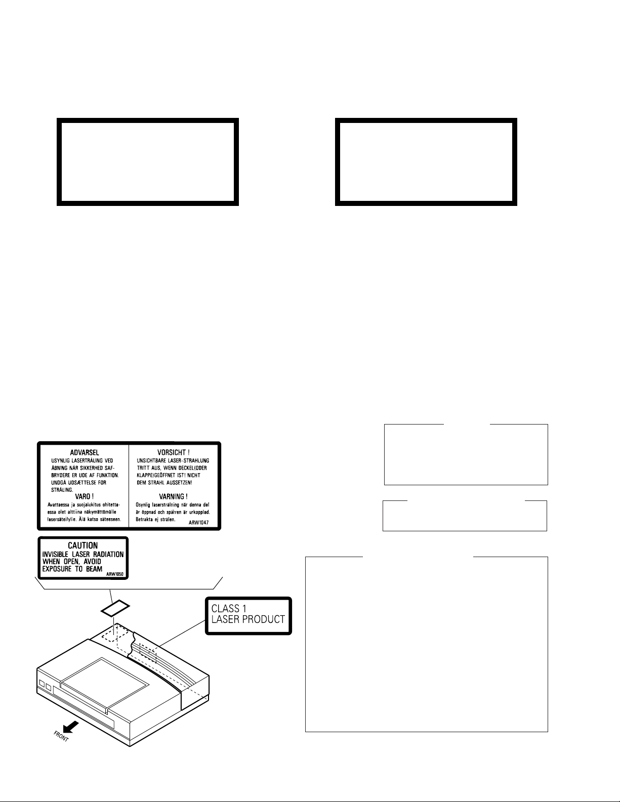
1. SAFETY INFORMATION
LITHIUM BATTERY NOTICE
WARNING!
Lithium batteries. Danger of explosion. Replacement must be done by
qualified personnel and only by following the instructions given in the
service manual.
This
warning is stated on the product or
in the operating instructions. When replacing the lithium batteries, follow the note
below.
Dispose
of
the used battery promptly.
Keep away from children. Do not disassemble and do not dispose of in fire.
The battery used in this device may present
a fire or chemical hazard if mistreated. Do
not recharge,
disassemble, heat above
100°C or incinerate. Replace only with the
same Part Number. Use of another battery
may present a risk of fire or explosion.
Note: The lithium battery installation po-
sition is shown in the exploded views.
LABEL CHECK
MYXK type
ADVARSEL!
Lithiumbatteri − Eksplosionsfare ved
fejlagtig håndtering. Udskiftning må kun
ske med batteri af samme fabrikat og
type. Levér det brugte batteri tilbage til
leverandøren.
Denne advarsel or angivet på produktet
eller i brugsvejledningen. Ved udskiftning
af lithium batterierne følges nedenstående
anveisning.
Batterierne
er af samme type og mærke.
må
kun udskiftes med batteri-
THIS PIONEER APPARATUS CONTAINS
LASER OF CLASS 1.
SERVICING OPERATION OF THE APPARATUS
SHOULD BE DONE BY A SPECIALLY
INSTRUTED PERSON.
IMPORTANT
LASER DIODE CHARACTERISTICS
MAXIMUM OUTPUT POWER: 5 mw
WAVELENGTH: 780 – 785 nm
NVXK type
Additional Laser Caution
1. Laser Interlock Mechanism
The loading position detect switch (in CD mechanism
assembly) is set to "CLMP ON(CD CLOSE)" (ON:low
level,OFF:high level) position, the system control
IC(IC5501) get the "CLMP" signal, and hand the laser
"LDON" signal to IC1101.
Then a laser diode can be lighted except when the level of
signal CLMP is low.
Printed on the Rear Panel
2
The interlock also does not function in the test mode∗.
Laser diode oscillation will continue, if pin 1 of CXA1821M
(IC1101) on the CDMAIN UNIT is connected to GND, or
pin 19 is connected to low level (ON), or else the terminals
of Q1101 are shorted to each other (fault condition).
2. When the cover is opened, close viewing of the objective
lens with the naked eye will cause exposure to a Class 1
laser beam.
∗ : Refer to page 41.
2. EXPLODED VIEWS AND PARTS LIST
NOTES:• Parts marked by "NSP" are generally unavailable because they are not in our Master Spare Parts List.
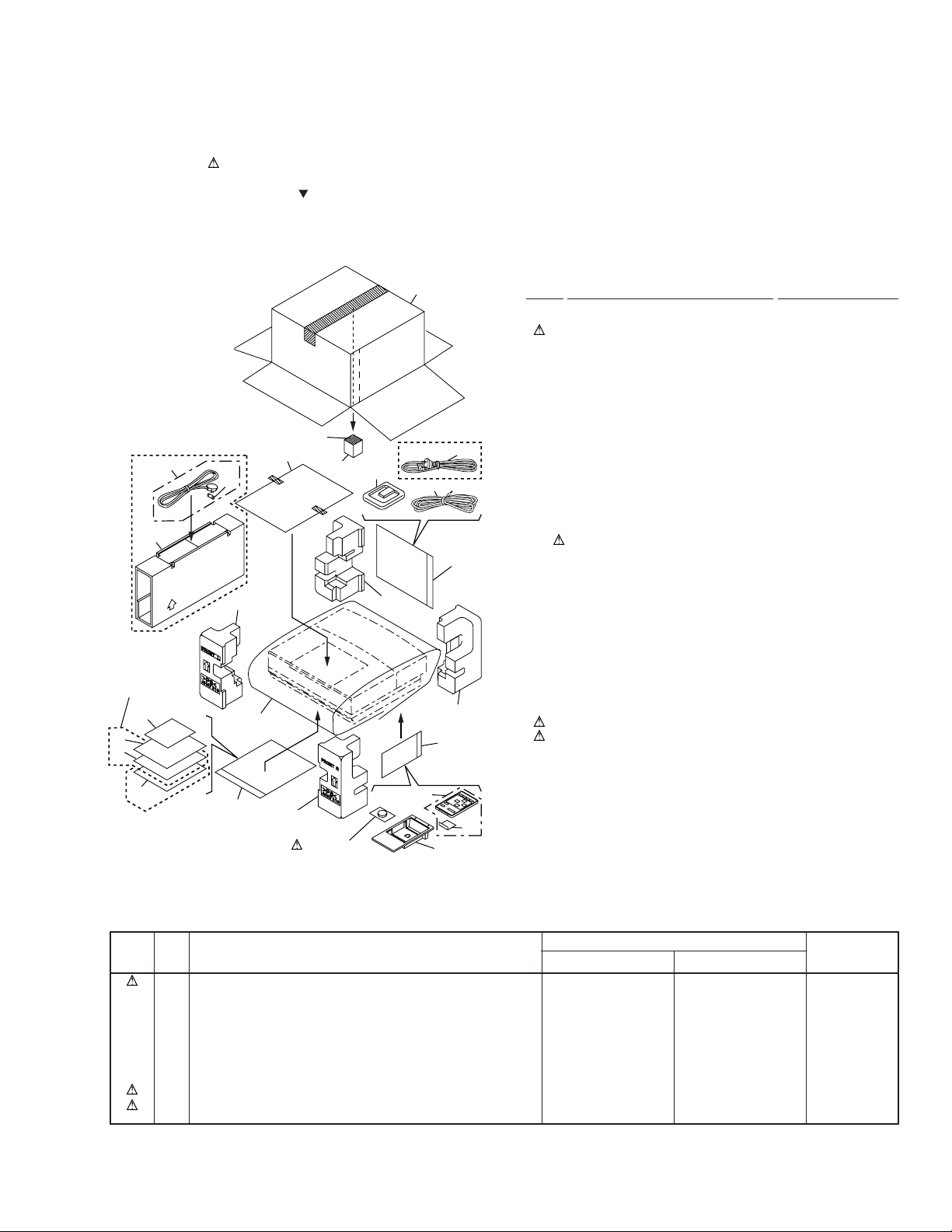
2.1 PACKING
The mark found on some component parts indicates the importance of the safety factor of the part.
•
Therefore, when replacing, be sure to use parts of identical designation.
Screws adjacent to mark on the product are used for disassembly.
•
(1) PACKING PARTS LIST
18
Mark No. Description Part No.
XC-L5
NVXK only
22
21
MYXK only
8
5
6
23
15(1/2)
19
2 Power Cord See Contrast table (2)
NSP 4 Vinyl Bag AHG7031
9
MYXK only
2
3
13
16(2/2)
4
NSP 7 Demo Caution ARR7016
NSP 8 Warranty Card (E-J) ARY7022
NSP 12 Lithium Battery (CR2025) VEM1009
NSP 14 Technibond431 AEH7006
22 Power Cord See Contrast table (2)
23 Fuse (T5A) See Contrast table (2)
14
7
17
16(1/2)
1 Remote Control Unit Holder AAH7013
3 FM Antenna ADH7005
5 Operating Instructions See Contrast table (2)
(English/French/German/Italian)
6 Operating Instructions See Contrast table (2)
(Dutch/Swedish/Spanish/Portuguese)
9 AM Loop Antenna ATB7007
10 Remote Control Unit AXD7170
(CU-XC005)
11 Battery Case AZE7116
13 Polyethylene Bag Z21-038
15 Pad F AHA7219
16 Pad R AHA7220
17 S Pad AHA7230
18 Packing Case See Contrast table (2)
19 Seat Z23-007
20 Operating Instructions See Contrast table (2)
(English)
21 Sub Packing See Contrast table (2)
20
NVXK only
13
15(2/2)
12
Litium Battery
10
11
1
(2) CONTRAST TABLE
MYXK and NVXK type are constructed the same except for the following :
Mark No. Symbol and Description
2 Power Cord ADG7010 Not used
5 Operating Instructions (English/French/German/Italian) ARE7171 Not used
6 Operating Instructions (Dutch/Swedish/Spanish/Portuguese) ARE7172 Not used
18 Packing Case AHD7619 AHD7620
20 Operating Instructions (English) Not used ARB7153
21 Sub Packing Not used AHD7618
22 Power Cord Not used ADG7009
23 Fuse (T5A) Not used AEK7001
MYXK type NVXK type
Part No.
Remarks
3
XC-L5
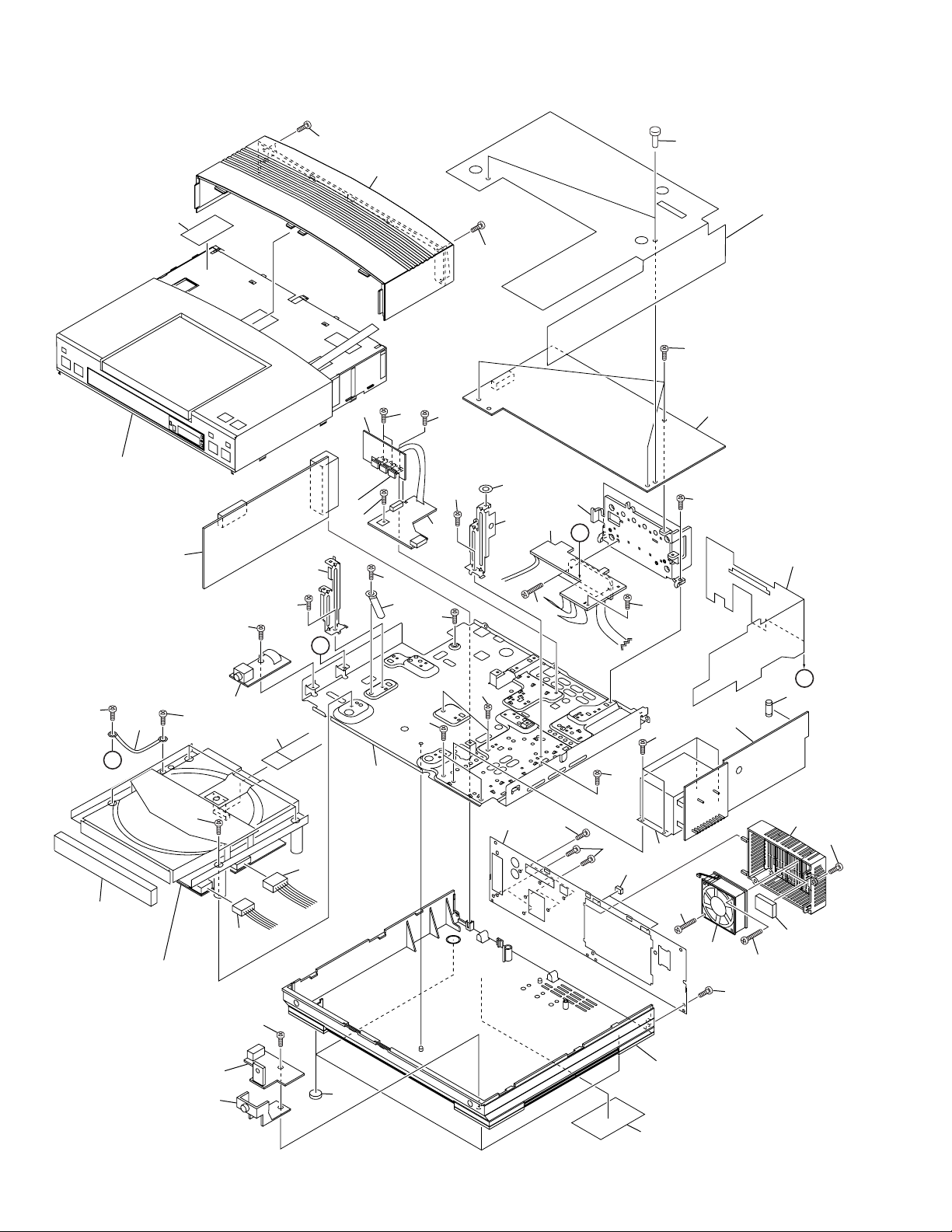
2.2 EXTERIOR
33
Refer to
"2.3 TOP PANEL ASSY".
9
35
35
23
39
5
35
31
39
6
35
35
26
23
36
24
2
B
38
27
35
8
38
43
20
35
1
35
19
35
A
35
25
A
28
16
Refer to
"2.6 CD MECHA ASSY".
35
41
29
4
10
15
14
39
7
17
38
22
38
21
39
39
37
3
38
12
42
40
13
40
39
30
B
11
32
39
18
34
4
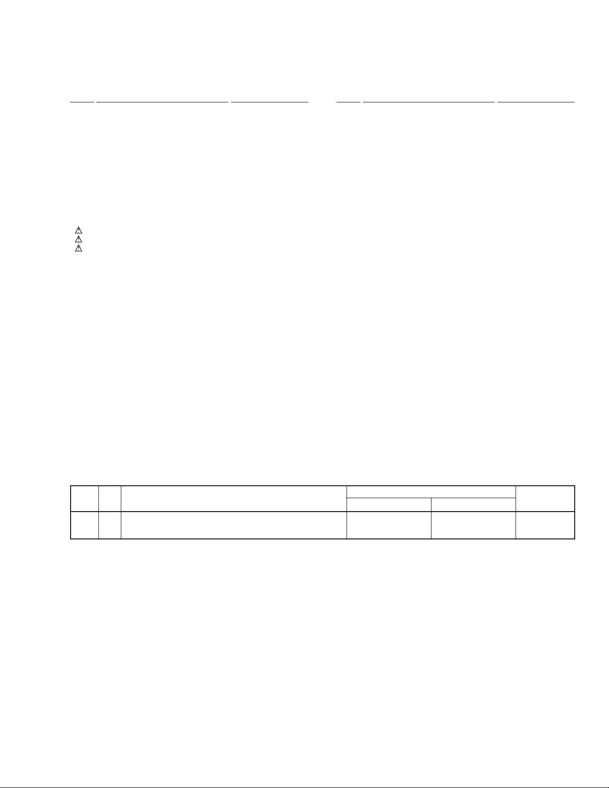
(1) EXTERIOR PARTS LIST
Mark No. Description Part No. Mark No. Description Part No.
XC-L5
1 CD MAIN UNIT AWU7090
2 CD AMP UNIT AWU7091
3 CD TRANS UNIT AWU7092
4 CD HP UNIT AWU7093
5 CD REG UNIT AWU7121
6 CD RECTIFY UNIT AWU7128
7 CD REM UNIT AWU7130
8 CD POWER UNIT AWU7153
9 FM/AM TUNER MODULE AXQ7077
10 16P F•F•C/30V ADD7096
11 Fuse FU1 (T800mA) AEK1053
12 Power Transformer (T1) ATS7218
13 DC Fan Motor AXM7003
14 Connector CN 5P AKP7040
15 Connector CN 6P AKP7041
16 CD MECHA Assy KSL-2130CCM
17 Leg AEB7090
18 F Cushion AEB7127
19 Center Barrier AEC7140
20 Top Barrier AEC7154
21 Rear Panel See Contrast table (2)
NSP 22 Bottom Plate ANF7010
23 Angle ANG7189
NSP 24 Heat Sink ANH7088
NSP 25 Cord With Plug J DE005VF0
NSP 26 Spacer PNM1135
27 Cord Clamper RNH-184
28 Tray Panel CD AAN7184
29 Lens AAX7639
30 Bottom Base AMA7005
31 Bonnet AMA7007
32 Rear Case AMR7207
NSP 33 Caution Label See Contrast table (2)
34 Name Label ARW7043
35 Screw BBZ30P060FMC
36 Screw BBZ30P140FMC
37 Screw BBZ40P060FMC
38 Screw BPZ30P060FZK
39 Screw BPZ30P100FZK
40 Screw BPZ30P300FMC
41 Screw PDZ30P060FMC
42 Cushion Rubber AEB7068
43 Rivet VEC1178
(2) CONTRAST TABLE
MYXK and NVXK type are constructed the same except for the following :
Mark No. Symbol and Description
21 Rear Panel ANC7672 ANC7673
NSP 33 Caution Label ARW1047 ARW1050
MYXK type NVXK type
Part No.
Remarks
5
XC-L5
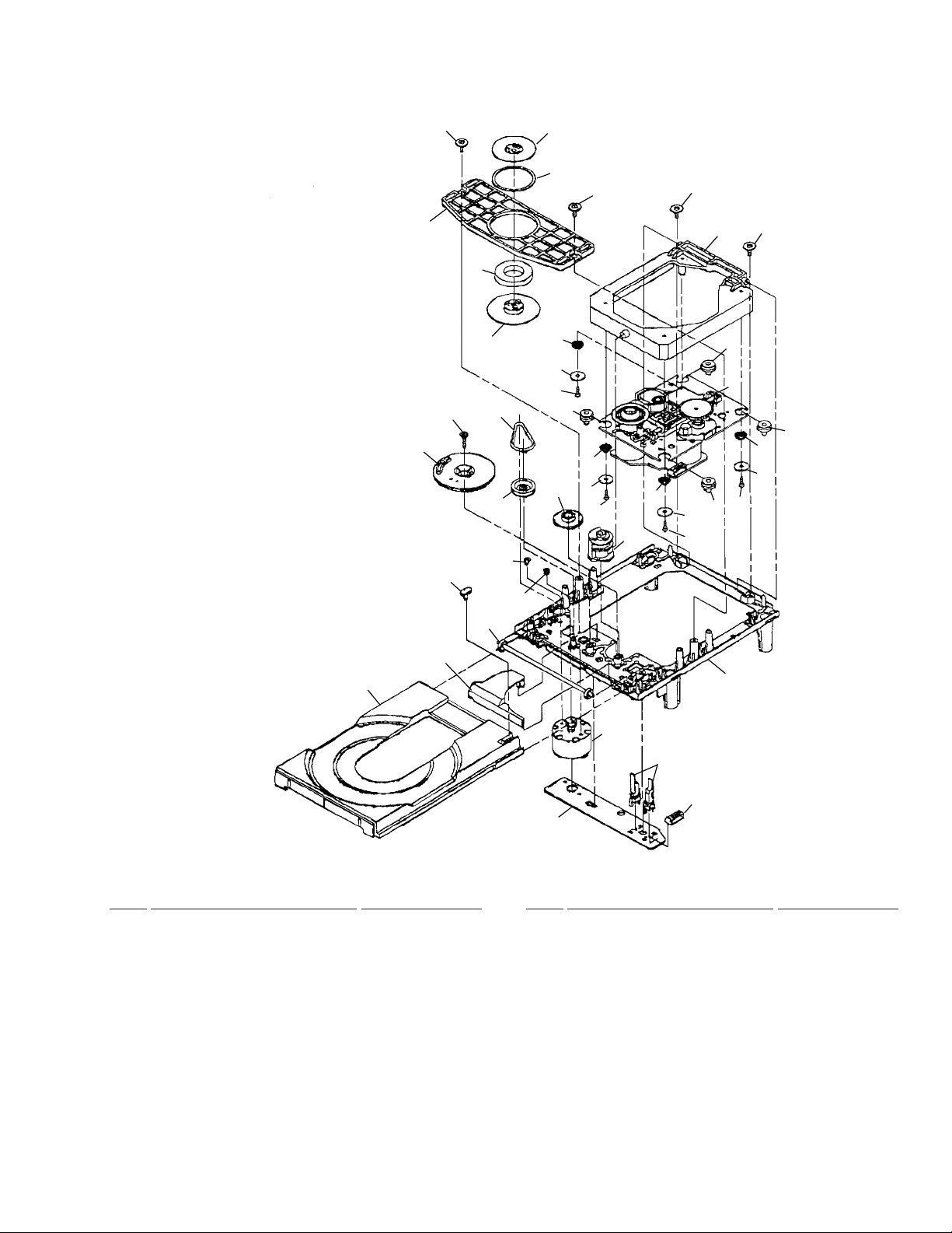
2.3 TOP PANEL ASSY
Top View Bottom View
19
14
Refer to
"2.4 DISPLAY ASSY".
19
18
4
13
2
19
8
16
19
5
1
9
10
11
12
6
16
Refer to
"2.5 GEAR HOLDER
ASSY".
19
17(1/2)
15
17(2/2)
TOP PANEL ASSY PARTS LIST
•
19
19
3
7
Mark No. Description Part No. Mark No. Description Part No.
1 CD TRADE UNIT AWU7095
2 CD KEYR UNIT AWU7096
3 CD KEYL UNIT AWU7097
4 CD POSIT UNIT AWU7100
5 17P F•F•C/60V ADD7098
6 Pin AMR7208
7 Holder L AMR7209
8 Holder R AMR7210
NSP 9 Top Plate ANK7042
10 Shaft ANL7010
11 Gear S ANW7120
12 Gear B ANW7121
13 Rivet VEC1178
14 Top Button AAD7476
15 Sub Panel AAP7048
16 Top Panel AMB7513
17 Button A Assy AWL7036
18 Screw IPZ20P060FMC
19 Screw VPZ30P080FZK
6
11
11
9
8
7
5
4
3
10
2
1
6
2.4 DISPLAY ASSY
XC-L5
DISPLAY ASSY PARTS LIST
•
Mark No. Description Part No.
1 CD FL UNIT AWU7094
2 8P F•F•C/60V ADD7099
3 Cushion Rubber AEB7068
4 D Cushion AEB7126
5 Rack Gear ANW7123
Mark No. Description Part No.
6 Front Plate AAH7012
7 Window AAK7575
8 FL Filter AEC7141
9 Display Panel AMB7517
10 Display Cover AMC7026
11 Screw VPZ30P080FZK
7
XC-L5
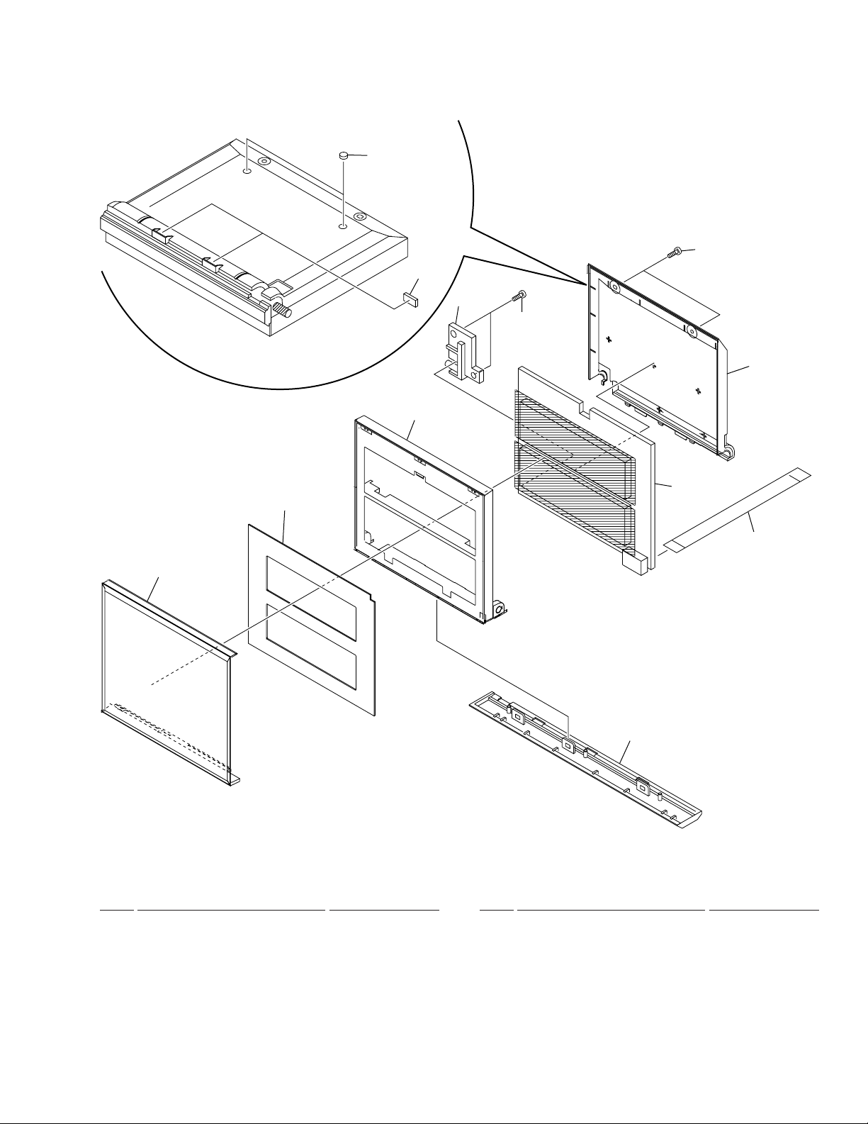
2.5 GEAR HOLDER ASSY
13
3
13
12
6
11
8
4
9
2
10
4.3 ± 0.3mm
1
5
13
7
GEAR HOLDER ASSY PARTS LIST
•
Mark No. Description Part No.
1 CD MOTOR UNIT AWU7098
2 CD SENSE UNIT AWU7099
3 Belt AEB7030
4 Gear Holder ANG7190
5 Gear A ANW7063
6 Gear Pulley A ANW7066
7 Select Gear ANW7067
8 FC Gear ANW7122
9 Motor Pulley PNW1634
10 DC Motor/0.75W PXM1010
11 Screw BBZ30P060FMC
12 Screw PMA26P040FMC
13 Washer WT36D072D025
8
XC-L5
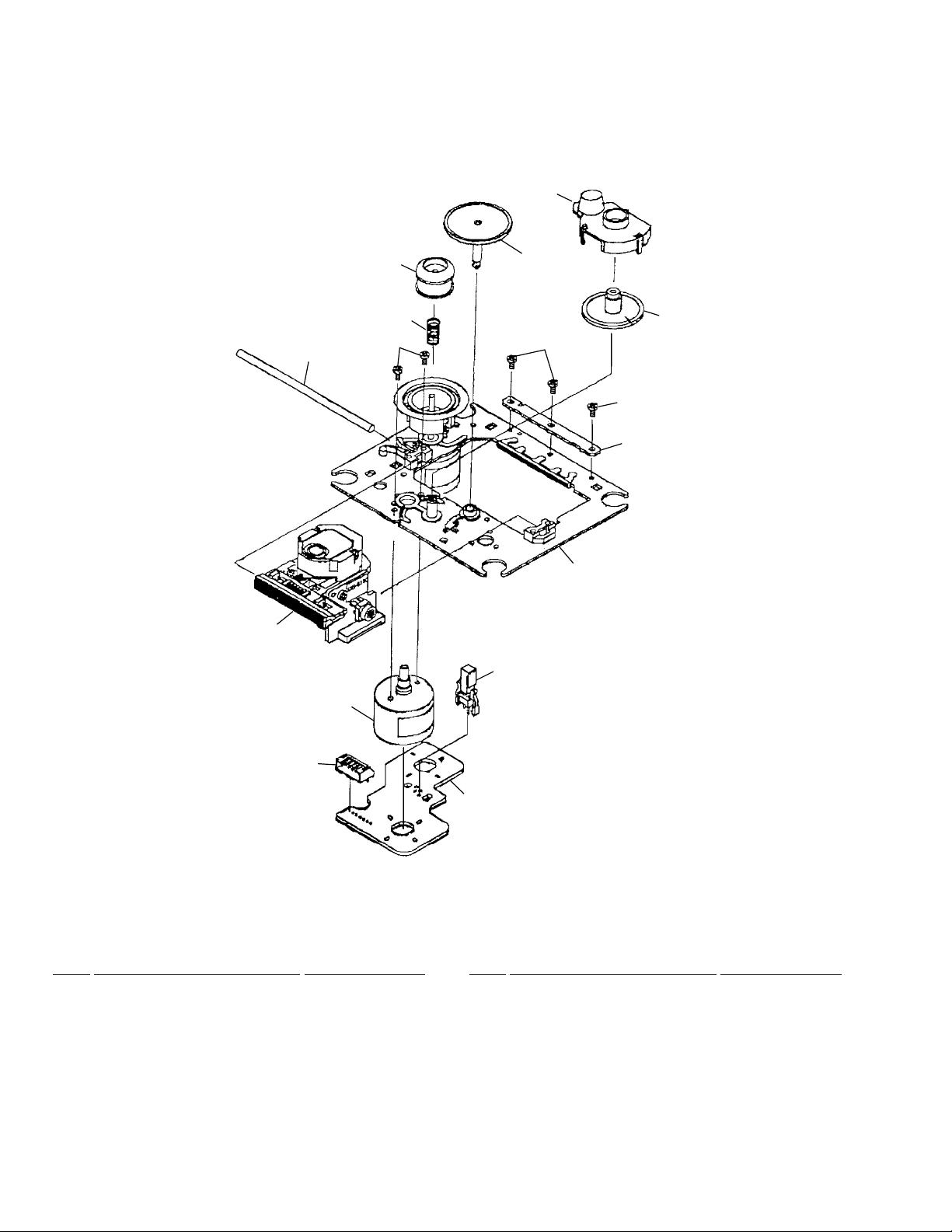
2.6 CD MECHA ASSY(1/2)
No supplied part
20
6
5
8
10
19
28
27
29
4
29
15
14
7
13
26
9
16
14
12
15
12
14
15
6
11
16
6
16
17
16
13
14
15
6
21
3
1
CD MECHA ASSY(1/2) PARTS LIST
•
25
22
24
18
23
Mark No. Description Part No. Mark No. Description Part No.
1 Tray(C) 2-646-290-01
2 • • • • •
3 Cover(S),Gear 2-625-544-(01)
4 Gear(S),Tray 2-625-535-(01)
5 Plate(S),Chucking 2-625-546-(01)
6 Screw +PTPWH2.6*7 2-626-294-(01)
7 Chucking Yoke(S) 2-625-537-(01)
8 Magnet 1-452-493-(21)
9 Damper(S) 2-625-541-(02)
10 Chucking Pully 2-646-291-(01)
11 Sub Chassis 2130 2-646-288-(01)
12 Coil Spring (Front) 2-627-236-(01)
13 Coil Spring (Back) 2-627-235-(01)
14 Washer 2130 2-646-289-(01)
15 Screw+P2.6*10 NOSLIT 7-685-135-(11)
16 Insulator 2-627-234-(01)
17 MD Assy A-4912-186-A
18 Outsert Main Chassis 2-625-552-(06)
19 Screw +PTPWH2.6*16 3-319-501-(51)
20 Drive Gear (S) 2-625-547-(01)
21 Control Cam(S) 2-625-545-(04)
22 Leaf Switch 1-692-667-(11)
23 Connector Pin 5p 1-564-721-(11)
24 Loading PC Board 1-640-523-(11)
25 Loading Motor Assy X-2625-117-(1)
26 Midway Gear (S) 2-625-534-(02)
27 Loading Pulley (S) 2-625-536-(02)
28 LM Berut 3-653-387-(00)
29 Screw +B2.6*2.5 2-625-279-(01)
9
XC-L5
2.7 CD MECHA ASSY(2/2)
No supplied part
14
11
10
3
2
5
4
9
12
12
13
1
6
8
7
CD MECHA ASSY(2/2) PARTS LIST
•
Mark No. Description Part No. Mark No. Description Part No.
1 Motor Chassis Assy X-2625-984-(1)
2 Motor Gear Assy X-2625-769-(1)
3 Sled Shaft 2-626-908-(01)
4 Gear (A)(S) 2-625-188-(02)
5 Screw +P2*3 7-621-255-(15)
6 Leaf Switch 1-572-085-(11)
7 Motor(6p)(S)PCB 1-639-678-(12)
8 Connector Pin 6p 1-564-722-(11)
9 Gear(B)(RP) 2-627-003-(01)
10 Spring(S)Compression 2-625-191-(01)
11 Ring(LO)(S),Center 2-625-477-(01)
12 Screw2*5,Tapping(S) 2-641-386-(01)
13 Reinforcement(S) 2-625-625-(01)
14 KSS-213C(Pic-up) 8-848-483-(05)
10

XC-L5
11
1
23
XC-L5
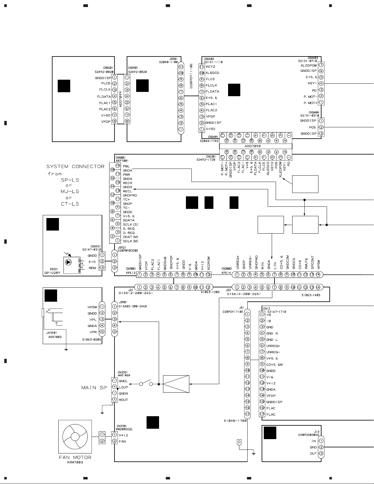
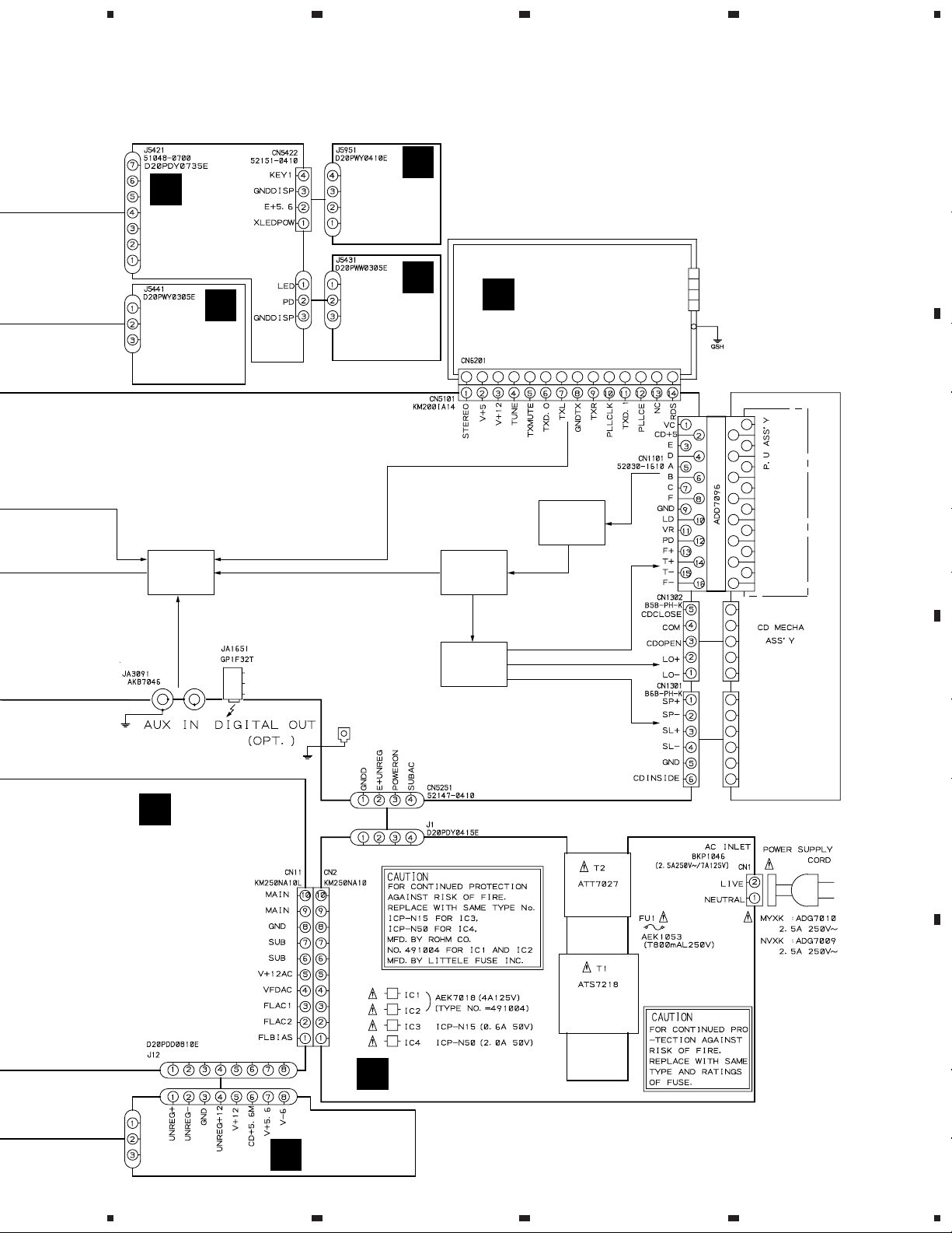
3. SCHEMATIC DIAGRAM
3.1 OVERALL CONNECTION DIAGRAM
A
4
L
CD FL
UNIT
(AWU7094)
K
CD
KEYR
UNIT
CD TRADE UNIT
J
(AWU7095)
(AWU7096)
B
B
(
B
1/2
,
B
2/2
)
IC5501
SYSTEM
ucom
CD MAIN UNIT
C
CD REM
UNIT
(AWU7090)
IC3001
VOL.IC
IC3121
SELECTOR
(AWU7130)
CD HP UNIT
I
C
D
(AWU7093)
GSH
DC
FAN MOTOR
AXM7003
GSH
RY3601
IC3301
POWER IC
CD AMP UNIT
H
(AWU7091)
G
CD REG UNIT
(AWU7121)
GSH
12
1234
5
Note : When ordering service parts, be sure to refer to
"EXPLODED VIEWS AND PARTS LIST" or "PCB PARTS LIST".
678
XC-L5
N
CD MOTOR
UNIT
(AWU7098)
CD
POSIT
UNIT
(AWU7100)
PB
IC3101
SELECTOR
AUX
M
TX
CD
O
CD KEYL
UNIT
(AWU7097)
P
CD SENSE
UNIT
(AWU7099)
A
IC1201
DECORDER
FM/AM TUNER
MODULE
(AXQ7077)
IC1101
RF AMP
KSS-213C
(8-848-483-(05))
A
B
GSH
CD RECTIFY
E
UNIT
(AWU7128)
GSH
IC1301
DRIVE IC
CD TRANS
D
UNIT (AWU7092)
POWER
TRANSFORMER
ATT7027
POWER
TRANSFORMER
ATS7218
CD
MECHA
ASSY
(KSL-2130CCM)
AC 220-230V
50 / 60Hz
AC POWER CORD
MYXK : ADG7010
NVXK : ADG7009
(2.5A 250V-)
C
D
CD POWER
UNIT
F
(AWU7153)
13
5
6
7
8
1
23
XC-L5
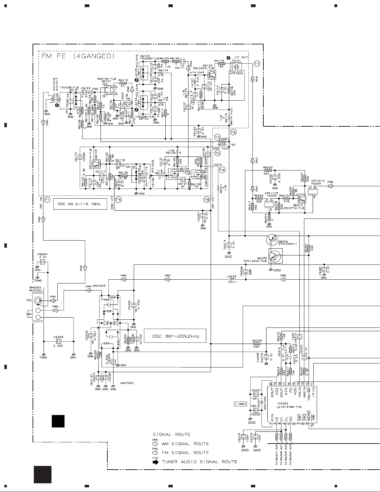
3.2 FM/AM TUNER MODULE
4
A
RF AMP
OSC
B
MIX AMP
BUFFER
IF AMP
FM +B SW
C
AM RF TUNING BLOCK
PLL
FM/AM TUNER MODULE
D
A
(AXQ7077)
14
A
1234
5
678
XC-L5
A
AF AMP
B
CN5101
2/2
B
AF AMP
REGULATOR
C
D
A
5
6
7
8
15
1
XC-L5
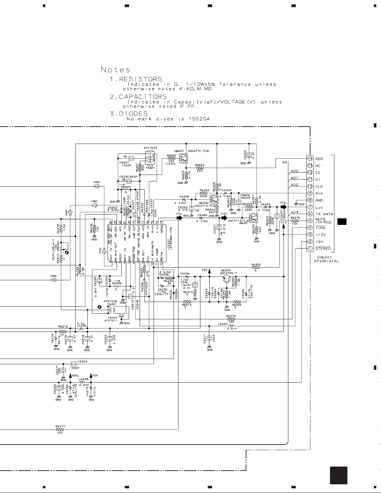
3.3 CD MAIN UNIT(1/2)
A
B
(FS)
(FS)
23
CD MAIN UNIT (1/2)
1/2
(AWU7090)
4
4.54V
5.70V
(SM)
(CM)
(CM)
(TS)
(TS)
(FS)
(FS)
(FS)
(TS)
(CM)
(LM)
(CM)
(SM)
(SM)
(CM)
(LM)
(LM)
(CM)
2.30V
(FS)
(FS)
B
(TS)
(TS)
2.37V
(LM)
(LM)
(SM)
(SM)
C
(CM)
(CM)
(TS)
(TS)
4.54V
2.30V
4.54V
CD MECHANISM ASSY
1
D
16
(FS)
(TS)
(TS)
(FS)
1/2B
2
VC
1234
(FS)
(TS)
5
678
XC-L5
SIGNAL ROUTE
(CD)
:CD AUDIO SIGNAL ROUTE
(FS)
: FOCUS SERVO LOOP LINE
(TS)
: TRACKING SERVO LOOP LINE
4.54V
(SM)
: SPINDLE MOTOR ROUTE
(CM)
: CARRIAGE MOTOR ROUTE
(LM)
: LOADING MOTOR ROUTE
A
2/2
B
(CD)
(CD)
DIGITAL OUT (OPT.)
Note: The encircled numbers denote measuring point in the schematic diagram.
B
C
IC1101- Pin 16:
1
PLAY MODE (RF)
H : 500nsec/div
1.2Vp-p
VC
IC1101- Pin 13 :
2
TEST MODE,
Tracking Open (TRER)
H : 5msec/div
3.5Vp-p
VC
D
VC : IC1101- Pin12
1/2B
5
6
7
8
17
1
23
XC-L5
3.4 CD MAIN (2/2) AND CD REM UNITS
A
CN5401
J
C
CD REM UNIT
(AWU7130)
B
B
4
1/2
J21
H
C
J22
5.57V
-5.95V
13.11V
13.38V
-13.78V
5.78V
H
4.57V
5.33V
9.08V
B
2/2
CD MAIN UNIT
D
18
(AWU7090)
5.63V
2/2B
1234
C
10.21V
D
AC 5.33V
J1
 Loading...