

Page 1
AUDIO/VIDEO MULTI-CHANNEL
RECEIVER
SINTOAMPLIFICATORE
AUDIO/VIDEO MULTICANALE
VSX-D712
VSX-D812
VSX-D912
Operating Instructions
Istruzioni per l’uso
Page 2
This product is for general household purposes.
Any failure due to use for other than household
purposes (such as long-term use for business
purposes in a restaurant or use in a car or ship) and
which requires repair will be charged for even
during the warranty period. K041_En
Installing the Receiver
VENTILATION: When installing this unit,
make sure to leave space around the unit for
ventilation to improve heat radiation (at least 60 cm
at top, 10 cm at rear, and 30 cm at each side).
WARNING: Slot and openings in the cabinet
are provided for ventilation and to ensure reliable
operation of the product and to protect it from
overheating, to prevent fire hazard, the openings
should never be blocked and covered with items,
such as newspapers, tablecloths, curtains, etc. Also
do not put the apparatus on the thick carpet, bed,
sofa, or fabric having a thick pile.
Operating Environment H045 En
Operating environment temperature and humidity:
+5°C – +35°C (+41°F – +95°F); less than 85%RH
(cooling vents not blocked)
Do not install in the following locations
• Location exposed to direct sunlight or strong
artificial light
• Location exposed to high humidity, or poorly
ventilated location
H040 En
Page 3

Thank you for buying this Pioneer product.
Please read through these operating instructions so that you will know how to operate your
model properly. After you have finished reading the instructions, put them in a safe place for
future reference.
01 Before you start
Checking what’s in the box
Installing the receiver
Making cable connections
Loading the batteries
Operating range of remote control unit
. . . . . . . . . . . . 5
. . . . . . . . . . . . . . . . . 5
. . . . . . . . . . . . . 5
. . . . . . . . . . . . . . . . . 5
. . . 6
02 5 minute guide
Introduction to home theater
Listening to Surround Sound
Using the Quick Setup
03 Quick surround sound setup
. . . . . . . . . . . 7
. . . . . . . . . . . 8
. . . . . . . . . . . . . . . 12
(VSX-D912 only)
Automatically calibrating your
listening area (MCACC)
. . . . . . . . . . . . . . 14
04 Connecting up
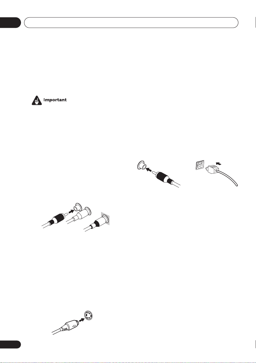
Audio/Video cords
S-video cables
Digital audio coaxial cords/
Optical cables
Connecting digital components
Connecting audio components
Connecting DVD multi-channel
components
Connecting video components
Connecting to the front panel
video terminal
Connecting antennas
FM wire antenna
AM loop antenna
Using external antennas
Connecting the speakers (VSX-D712)
Connecting the speakers
(VSX-D812/D912)
Speaker terminals
A and B speaker systems
Hints on speaker placement
Connecting additional amplifiers
Power cord caution
. . . . . . . . . . . . . . . . . . 16
. . . . . . . . . . . . . . . . . . . . . 16
. . . . . . . . . . . . . . . . . . . . . 16
. . . . . . . . 17
. . . . . . . . 18
. . . . . . . . . . . . . . . . . . . . . . . 19
. . . . . . . . . 20
. . . . . . . . . . . . . . . . . . . . 20
. . . . . . . . . . . . . . . . 21
. . . . . . . . . . . . . . . . . . 21
. . . . . . . . . . . . . . . . . . 21
. . . . . . . . . . . . 21
. . . . 22
. . . . . . . . . . . . . . . . . . . 23
. . . . . . . . . . . . . . . . . 24
. . . . . . . . . . . . 24
. . . . . . . . . 24
. . . . . . . 26
. . . . . . . . . . . . . . . . 27
Operating other Pioneer components
. . . .27
05 Controls and displays
Front panel
Display
Remote control
. . . . . . . . . . . . . . . . . . . . . . . .28
. . . . . . . . . . . . . . . . . . . . . . . . . . .30
. . . . . . . . . . . . . . . . . . . . .32
06 Playing sources
Introduction to Sound Modes
Stereo/Direct
Standard mode
Advanced Surround modes
Choosing the input signal . . . . . . . . . . . . . 36
Listening to multi-channel playback . . . . .37
Using Stereo/Direct. . . . . . . . . . . . . . . . . .38
Using Advanced Surround . . . . . . . . . . . .38
Using the Surround Back Channel
(SB CH) . . . . . . . . . . . . . . . . . . . . . . . . . . .39
Using the Virtual Surround Back
mode (VSB) . . . . . . . . . . . . . . . . . . . . . . . .40
Using Midnight and Loudness listening . .41
Using the tone controls . . . . . . . . . . . . . . .41
Playing other sources . . . . . . . . . . . . . . . .41
Selecting the multi-channel
analog inputs . . . . . . . . . . . . . . . . . . . . . .42
Using the sleep timer . . . . . . . . . . . . . . . .42
. . . . . . . . . . . . . . . . . . . . . .35
. . . . . . . . . . . . . . . . . . . .35
. . . . . . . . . .35
. . . . . . . . . . .36
07 Setting up
Choosing your receiver setup . . . . . . . . . .43
Speaker setting . . . . . . . . . . . . . . . . . . . . 44
Surround back speaker setting . . . . . . . .45
Subwoofer setting . . . . . . . . . . . . . . . . . .45
Crossover frequency setting . . . . . . . . . .45
LFE attenuator setting. . . . . . . . . . . . . . .46
Front left speaker distance setting . . . . .46
Center speaker distance setting . . . . . . .46
Front right speaker distance setting . . . .47
Surround right speaker distance
setting. . . . . . . . . . . . . . . . . . . . . . . . . . . 47
Surround back speaker distance
setting. . . . . . . . . . . . . . . . . . . . . . . . . . . 47
English Italiano Français
Nederlands
EspañolDeutsch
Page 4
Surround left speaker distance
. . . . . . . . . . . . . . . . . . . . . . . . . . 47
setting
Subwoofer distance setting
Dynamic range control setting
Dual mono setting
Surround back channel input
setting (VSX-D812/D912 only)
Digital input settings
Manually calibrating your listening
area (MCACC)
Setting separate channel levels for
listening modes
. . . . . . . . . . . . . . . . . 48
. . . . . . . . . . . . . . . . . . . . . 49
. . . . . . . . . . . . . . . . . . . . 51
. . . . . . . . . . 47
. . . . . . . . 48
. . . . . . . . 48
. . . . . . . . . . . . . . . 48
08 Using the tuner
Listening to the radio
Improving FM stereo sound
Using the RF attenuator
Tuning directly to a station
Saving station presets
Naming station presets
Listening to station presets
An introduction to RDS
Displaying RDS information
Searching for RDS programs
An introduction to EON
Using EON
Clearing all stations from the
RDS and EON searches
. . . . . . . . . . . . . . . . . . . . . . . 57
. . . . . . . . . . . . . . . . 52
. . . . . . . . . . 52
. . . . . . . . . . . . . 52
. . . . . . . . . . . 52
. . . . . . . . . . . . . . . 53
. . . . . . . . . . . . . 54
. . . . . . . . . . 55
. . . . . . . . . . . . . . 55
. . . . . . . . . 56
. . . . . . . . . 56
. . . . . . . . . . . . . . 57
. . . . . . . . . . . . . 58
09 Making recordings
Making an audio or a video recording
. . . 59
Programming signals from other
remote controls (VSX-D812/D912 only)
Erasing all of your programmed
settings (VSX-D812/D912 only)
Clearing all the remote control
settings
Direct function
Controls for TVs
Controls for other components
Preset Code List (VSX-D712 only)
Preset Code List (VSX-D812/D912 only)
. . . . . . . . . . . . . . . . . . . . . . . . . . .62
. . . . . . . . . . . . . . . . . . . . .62
. . . . . . . . . . . . . . . . . . . . .63
. . . . . . . . .62
. . . . . . . . .64
. . . . . . . .67
11 Additional information
Troubleshooting
Resetting the main unit
Specifications
Amplifier section
Video Section
FM Tuner Section
AM Tuner Section
Miscellaneous
Cleaning the unit
"DTS" ,"DTS-ES Extended Surround" and
"Neo:6" are trademarks of Digital Theater
Systems, Inc.
Manufactured under license from Dolby
Laboratories. "Dolby", "Pro Logic",
"Surround EX", and the double-D symbol
are trademarks of Dolby Laboratories.
. . . . . . . . . . . . . . . . . . . .70
. . . . . . . . . . . . . . .72
. . . . . . . . . . . . . . . . . . . . . .73
. . . . . . . . . . . . . . . . . . .73
. . . . . . . . . . . . . . . . . . . . .73
. . . . . . . . . . . . . . . . . .73
. . . . . . . . . . . . . . . . . .73
. . . . . . . . . . . . . . . . . . . . .74
. . . . . . . . . . . . . . . . . . .74
. . .61
. . .68
10 Controlling the rest of your
system
Setting the remote to control other
components
Selecting preset codes directly
. . . . . . . . . . . . . . . . . . . . . . . 60
. . . . . . . . . 60
Page 5
Before you start
01
Chapter 1:
Before you start
Checking what’s in the box
Please check that you've received the
following supplied accessories:
• AM loop antenna
• FM wire antenna
• Dry cell batteries (AA size IEC R6) x2
• Remote control
• Microphone (VSX-D912 only)
• Microphone stand (VSX-D912 only)
• These operating instructions
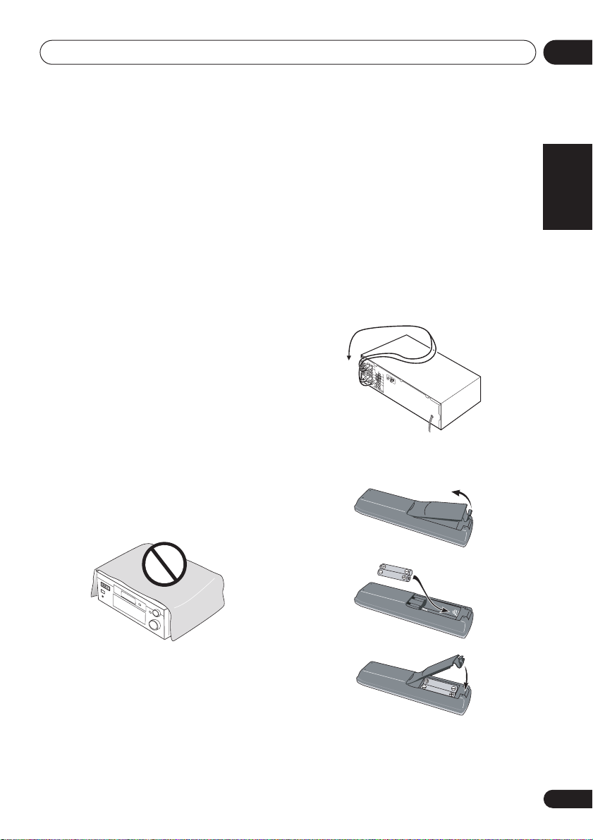
Installing the receiver
Please note the following points:
• Do not place objects directly on top of this
unit. This prevents proper heat dispersal.
• When installing on a rack, shelf, etc., be
sure to leave more than 20 cm. of space
above the receiver.
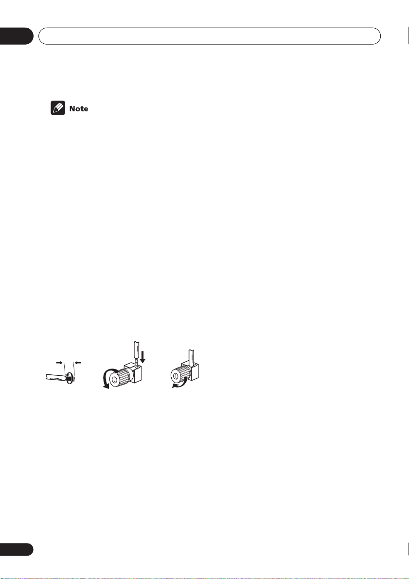
Making cable connections
Make sure not to bend the cables over the top
of this unit (as shown in the illustration). If this
happens, the magnetic field produced by the
transformers in this unit may cause a
humming noise from the speakers.
Loading the batteries
English Italiano Français
Nederlands
EspañolDeutsch
5
En
Page 6
01
Before you start
Incorrect use of batteries may result in such
hazards as leakage and bursting. Observe the
following precautions:
• Never use new and old batteries together.
• Insert the plus and minus sides of the
batteries properly according to the marks
in the battery case.
• Batteries with the same shape may have
different voltages. Do not use different
batteries together.
• When disposing of used batteries, please
comply with governmental regulations or
environmental public instruction’s rules
that apply in your country or area.
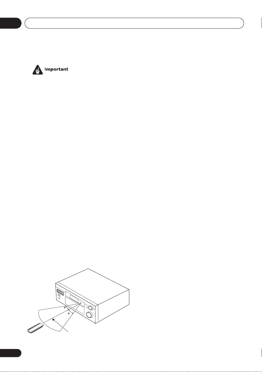
Operating range of remote
control unit
The remote control may not work properly if:
• There are obstacles between the remote
control and the receiver's remote sensor.
• Direct sunlight or fluorescent light is
shining onto the remote sensor.
• The receiver is located near a device that
is emitting infrared rays.
• The receiver is operated simultaneously
with another infrared remote control unit.
6
En
30
30
7m
Page 7

5 minute guide
02
Chapter 2:
5 minute guide
Introduction to home theater
You are probably used to using stereo equipment to listen to music, but may not be used to
home theater systems that give you many more options (such as surround sound) when
listening to soundtracks.
Home theater refers to the use of multiple audio tracks to create a surround sound effect,
making you feel like you're in the middle of the action or concert. The surround sound you get
from a home theater system depends not only on the speakers you have set up in your room, but
also on the source and the sound settings of the receiver.
DVD-Video has become the basic source material for home theater due to its size, quality, and
ease of use. Depending on the DVD, you can have up to seven different audio tracks coming
from one disc, all of them being sent to different speakers in your system. This is what creates
a surround sound effect and gives you the feeling of ‘being there’.
This receiver will automatically decode Dolby Digital, DTS, or Dolby Surround DVD-Video discs,
according to your speaker setup. In most cases, you won’t have to make changes for realistic
surround sound, but other possibilities (like listening to a CD with multi-channel surround
sound) are explained in
Playing sources
on page 35.
English Italiano Français
Nederlands
EspañolDeutsch
7
En
Page 8
02
5 minute guide
Listening to Surround Sound
This receiver was designed with the easiest possible setup in mind, so with the following quick
setup guide, you should have your system hooked up for surround sound in no time at all. In
most cases, you can simply leave the receiver in the default settings.
Be sure to complete all connections before connecting this unit to the AC power source.
1 Hook up your DVD player.
For surround sound, you’ll want to hook up using a digital connection from the DVD player to
the receiver. You can do this with either a coaxial, or an optical connection (you don’t need to
connect both). If you hook up using an optical cable, you should refer to
on page 48 to assign the optical input to
DVD
.
Use a video cord to connect the video output on your DVD player to the receiver using the jacks
shown below.
2 Hook up your TV.
Use a video cord to connect your receiver to the TV using the jacks as shown below.
Digital input settings
Optical cable
DIGITAL OUT
STANDBY/ON
0
DVD player
TV
DIGITAL
OUT
OPT
Coaxial
cable
DVD PLAYER
Î
8
¡¢41
7
3
VIDEO OUT
S
(CD-R/TAPE/MD)
ASSIGNABLE
DIGITAL
IN
COAX
COAX
OPT
2
OPT
1
(TV /
SA T)
2
(CD)
1
(DVD
/LD)
DIGITAL
(CD-R/TAPE/MD)
ASSIGNABLE
DIGITAL
IN
IN
OUT
IN
OPT
OPT
OUT
2
IN
OPT
1
(TV/
IN
SAT)
COAX
2
IN
(CD)
COAX
1
OUT
(DVD
/LD)
IN
R
DVD
/ LD
FRONT
REC
CD-R
/ TAPE
/ MD
AUDIO
D V D
7.1CH
INPUT
VIDEO IN
AM
FM UNBAL
LOOP
75
Ω
AUX
CD
ANTENNA
MONITOR OUT
VCR/
OUT IN
DVR
CONTROL
VIDEO
IN
TV/
OUT
SAT
IN
DVD
MONITOR
/ LD
OUT
FRONT
D V D
7.1CH
SUB
INPUT
REC
WOOFER
IN
CD-R
PREOUT
/ TAPE
/ MD
S-VIDEO
PLAY
L
IN
Video cord
CEN-
SUB WOOFER
TER
SURROUND
LR
SURROUND
BACK
LR
DVD 7.1CH INPUT
OUT
VCR/
FRONT
RL R
DVR
S
IN
VIDEO
P
E
TV/
SAT
A
IN
A
K
DVD/
LD
E
IN
IN
R
S
This receiver*
LL
RR
FRONT CENTER
SURROUND BACK
RL
OUT
SINGLE
SEE INSTRUCTION
MANUAL
MONITOR
OUT
SUB
WOOFER
PREOUT
SURROUND
IN
Video cord
*
The illustration shows the VSX-D812/D912, but connections for the VSX-D712 are the same.
PREOUT
SURROUND
BACK
FRONTCENTER SURROUND
LR L
B
8
En
Page 9
5 minute guide
OOP
UNBAL
OUT
ed
subwoofer
SW
02
3 Connect your speakers.
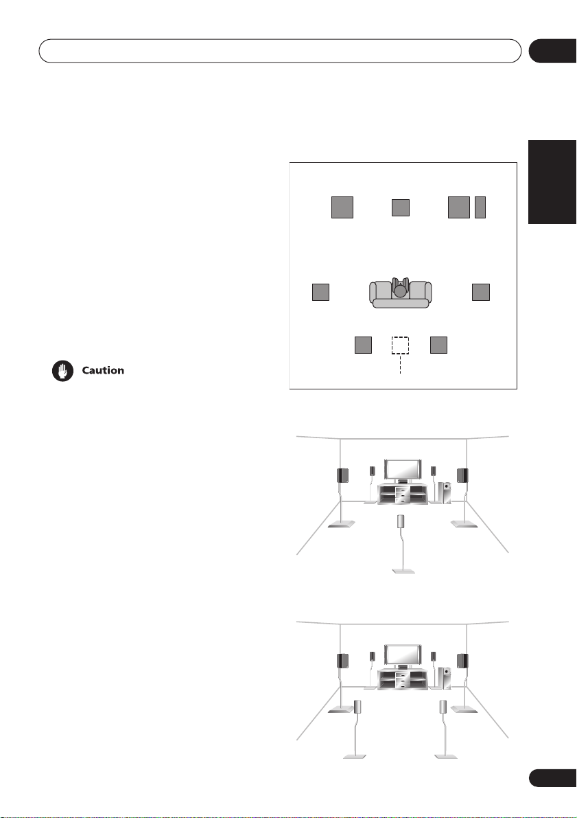
A complete setup of speakers is shown here (six speakers for the VSX-D712, and eight for the
VSX-D812/D912), but everyone’s home setup will vary. Simply connect the speakers you have in
the manner shown below. The receiver will work with just two stereo speakers (the front
speakers in the diagram) but using at least three speakers is recommended, and a complete
setup is best.
Make sure you connect the speaker on the right to the right terminal and the speaker on the left
to the left terminal. Also make sure the positive and negative (
+/–
) terminals on the receiver
match those on the speakers.
• Use speakers with a nominal impedance of 8
• If you’re not using a subwoofer, change the front speaker setting (see
Ω
to 16 Ω.
Speaker setting
on
page 44) to large.
Front speakers
LR C LSRS
L
MONITOR OUT
SURROUND
CONTROL
OUT
MONITOR
OUT
SUB
WOOFER
PREOUT
SURROUND
BACK
S-VIDEO
DVD 5.1CH INPUT
OUT
VCR/
FRONT
RL R LRL
DVR
S
IN
P
E
TV/
SAT
A
IN
A
K
DVD/
LD
E
IN
R
S
ASSIGNABLE
DIGITAL
IN
VCR/
OUT
OUT IN
DVR
IN
OPT
1
(TV/
IN
SAT )
COAX
2
IN
(CD)
COAX
1
OUT
(DVD
/LD)
IN
R
VIDEO
IN
TV/
SAT
IN
DVD
/ LD
FRONT
D V D
5.1CH
INPUT
REC
IN
CD-R
/ TAPE
/ MD
PLAY
L
AUDIO
Surround speakersCenter speaker
FRONTCENTER SURROUND
B
VSX-D712
Power
English Italiano Français
Nederlands
EspañolDeutsch
9
En
Page 10
02
S
R
CEN-
UX
OUT
SURROUND
INPUT
ed
subwoofer
SW
surround
bac
r
5 minute guide
Front speakers
Center speaker
Surround speakers
LR C LSRS
S-VIDEO
UB WOOFE
SURROUND
LR
SURROUND
BACK
LR
DVD 7.1CH INPUT
OUT
VCR/
FRONT
RL R
DVR
S
IN
P
E
TV/
SAT
A
IN
A
K
DVD/
LD
E
IN
R
S
BACK
RR
FRONT CENTER
SURROUND
SURROUND BACK
RL
SINGLE
SEE INSTRUCTION
MANUAL
LR L
DIGITAL
OUT
(CD-R/TAPE/MD)
ASSIGNABLE
DIGITAL
IN
A
CD
IN
OPT
OPT
OUT
2
IN
OPT
1
(TV/
IN
SAT)
COAX
2
IN
(CD)
COAX
1
OUT
(DVD
/LD)
IN
ANTENNA
OUT IN
VIDEO
IN
IN
D V D
7.1CH
INPUT
IN
CONTROL
OUT
MONITOR
OUT
SUB
WOOFER
PREOUT
MONITOR OUT
VCR/
DVR
TV/
SAT
DVD
/ LD
FRONT
REC
CD-R
/ TAPE
/ MD
PLAY
R
L
AUDIO
Surround back speakers
SBL SBR
FRONTCENTER SURROUND
B
VSX-D812/D912
Passive
Power
subwoofer
or single
TV
k
speake
VSX-D812/D912 only
• To use the speaker on your TV as the center speaker (C), connect the
CENTER PREOUT
on this unit to the audio input jack on your TV. In this case the center speaker shown is
unnecessary.
jack
10
En
Page 11
5 minute guide
02
• If you are using only one surround back speaker, connect the positive wire to the right
channel (
• If you select subwoofer (
hook up a subwoofer instead of speakers to the surround back speaker terminals. Connect
the wires just as above (and as shown below), connecting the positive wire to the right
channel (
4 Plug in the receiver and switch it on, followed by your DVD player, your subwoofer
and the TV.
Make sure you’ve set the video input on your TV to this receiver. Check the manual that came
with the TV if you don’t know how to do this.
Also make sure that
is selected. If it isn’t, press
5 Press QUICK SETUP on the front panel to specify your speaker setup, room size and
listening position.
Use the
Setup
VSX-D912 only
• For a more complete surround sound setup, we recommend using the automatic MCACC
setup in the
6 Play a DVD, and adjust the volume to your liking.
There are several other sound options you can select. See
page 35 for more on this. See also
options.
+
) terminal, and the negative wire to the left channel (–) terminal (shown below).
SB SW
) in the
Surround back speaker setting
+
) terminal, and the negative wire to the left channel (–) terminal.
Surround back
speaker (or
subwoofer)
VSX-D812/D912
SURROUND BACK
RL
DVD/LD
MULTI JOG
on page 12 if you’re unsure about the settings.
dial to select and
Quick surround sound setup
is showing in the receiver’s display, indicating that the DVD input
DVD
on the remote control to set the receiver to the DVD input.
ENTER
to confirm your selection. See
on page 14.
Choosing your receiver setup
on page 45 you can
Using the Quick
Introduction to Sound Modes
on page 43 for more setup
on
English Italiano Français
Nederlands
EspañolDeutsch
• Depending on your DVD player or source discs, you may only get digital 2 channel stereo
and analog sound. In this case, the listening mode must be set to
already be set—see
you want multi-channel surround sound.
Listening to multi-channel playback
on page 37 if you need to do this) if
STANDARD
(it should
11
En
Page 12
02
5 minute guide
Using the Quick Setup
You can use the Quick Setup to get your
system up and running with just a few button
presses. The receiver automatically makes
the necessary settings after you have selected
your speaker setup, room size and listening
position.
Note that with the VSX-D912 you don’t have to
make these settings if you use the automatic
MCACC setup instead (in this case, go
straight to the
page 14).
If you want to make more specific settings,
refer to
page 43.
Use the front panel controls for the steps
below.
STEREO/
DVANCED
URROUND
DIRECT
ENING MODE
L DIMMER
Quick surround sound setup
Choosing your receiver setup
ENTER
SIGNAL
MIDNIGHT/
LOUDNESS
SPEAKERS
DIGITAL IN
MONITOR T ONE QUICK SETUP
MULTI JOG
VIDEO INPUT
S-VIDEO VIDEO L AUDIO R
DOWN UP
SELECT
on
on
MULTI JOG
MASTER VOLUME
R
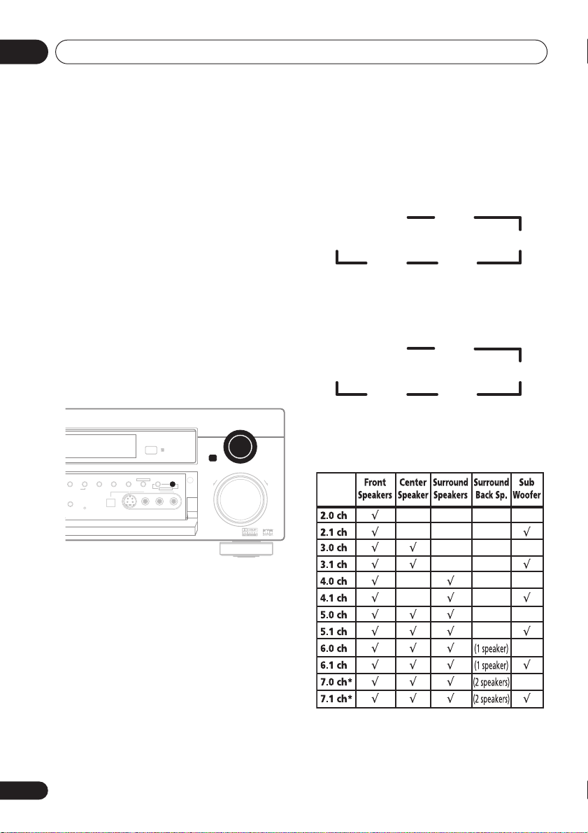
3 Use the MULTI JOG dial to choose your
speaker setup.
When a subwoofer was detected in step 2, you
can cycle between the following choices:
2.1ch 3.1ch
7.1ch*
4.1ch
6.1ch 5.1ch
*
VSX-D812/D912 only
If a subwoofer wasn’t detected in step 2, you
can cycle between the following choices:
2.0ch 3.0ch
7.0ch*
4.0ch
6.0ch 5.0ch
*
VSX-D812/D912 only
• Check the table below to find the speaker
setup that corresponds with your system.
1 If the receiver is off, press
STANDBY/ON to turn the power on.
The
STANDBY
indicator goes out.
2 Press QUICK SETUP.
SW DET
flashes in the display while the
receiver checks your setup for a subwoofer.
SW YES
or
SW NO
confirms the subwoofer
check, then the display prompts you to select
your speaker setup.
12
En
*
VSX-D812/D912 only
Page 13

5 minute guide
02
4 Press ENTER.
5 Use the MULTI JOG dial to choose your
room size.
Depending on the distance of your speakers
from the listening position, choose between
small, medium, or large (
an average-sized room.
6 Press ENTER.
7 Use the MULTI JOG dial to choose your
listening position.
You can cycle between the following choices:
FWD
BACK
FWD
– If you are nearer to the front
speakers than the surround speakers
MID
– If you are equal distance from the
front and surround speakers
BACK
– If you are nearer to the surround
speakers than the front speakers
8 Press ENTER to confirm your setup.
The display shows the speaker setup, room
size and listening position that you have
selected.
S, M
or L), M being
MID
English Italiano Français
Nederlands
EspañolDeutsch
13
En
Page 14
03
Quick surround sound setup
Chapter 3:
Quick surround sound setup
VSX-D912 only
Automatically calibrating
your listening area (MCACC)
The Multi-Channel Acoustic Calibration
(MCACC) system measures the acoustic
characteristics of your listening area, taking
into account ambient noise, speaker size and
distance, and tests for both channel delay and
channel level. After you have set up the
microphone provided with your system, the
receiver uses the information from a series of
test tones to optimize the speaker settings
and equalization for your particular room.
RECEIVER
ENTER
MCACC
SETUP
• These test tones can be loud, so take care
that there is no one in the room who will
be startled by the noise.
• Make sure the mic and speakers are not
moved during the MCACC setup.
14
En
1 Connect the microphone to the SETUP
MIC jack on the front panel.
2 Place the microphone at your normal
listening position.
Place the mic about ear level at your normal
listening position using the supplied microphone stand on a table or chair.
Make sure there are no obstacles between the
speakers and the microphone.
3 If the receiver is off, press
STANDBY/ON to turn the power on.
The
STANDBY
4 If you have a subwoofer, turn it on.
5 Press RECEIVER.
6 Press MCACC SETUP.
Try to be as quiet as possible after pressing
MCACC SETUP
of test tones to establish the ambient noise
level.
If the noise level is too high,
the display for five seconds. To exit and check
the noise levels again, press
(see the notes regarding ambient noise levels
below) or press
to
GO NEXT?
The system now checks the microphone and
your speaker setup.
If you see an
there may be a problem with your mic or the
speaker connections.
Turn off the power, and check the problem
indicated by the
then try the auto surround setup again.
•
ERR MIC
connection.
indicator goes out.
. The system outputs a series
NOISY!
blinks in
MCACC SETUP
ENTER
when you’re prompted
ERR
message in the display,
ERR
message (see below),
– Check the microphone
Page 15
Quick surround sound setup
•
ERR Fch
connections.
•
ERR Sch
surround back speaker connections.
•
ERR SW
been switched on and volume on the
subwoofer is turned up.
7 Use and to select the speaker
system that corresponds to your setup.
Cycle between the following choices:
7.1ch*
7.0ch
* Indicates a subwoofer is included in your
speaker setup
See the table on page 12 if you’re unsure
which speaker system to select.
8 If you selected a speaker system that
includes a subwoofer, press ENTER to
check the subwoofer output level.
If the subwoofer output level is too high/low,
SW.VOL.UP/SW.VOL.DWN
display for five seconds. To exit and check
your subwoofer output level, press
SETUP
below) or simply turn the subwoofer volume
up or down (as indicated), then press
when you’re prompted to
9 Press ENTER to finish the auto
surround setup.
The system checks for speaker size, channel
delay and channel level. If you have
connected a subwoofer, it will check for
ambient noise once again.
When the auto surround setup is complete,
the volume level returns to normal and
COMPLETE
display.
– Check the front speaker
– Check the surround or
– Make sure the subwoofer has
2.0ch 2.1ch* 3.1ch*3.0ch
4.0ch
4.1ch*
6.1ch* 6.0ch 5.0ch5.1ch*
blinks in the
MCACC
(see the notes regarding noise levels
ENTER
GO NEXT?
, then
RESUME
shows in the
• If the room environment is not optimal for
the auto surround setup (too much
ambient noise, echo off the walls, obstacles blocking the speakers from the
microphone) the final settings may be
incorrect. Check for household appliances (air conditioner, fridge, fan, etc.),
that may be affecting the environment
and switch them off if necessary.
• Some older TVs may interfere with the
operation of the mic. If this seems to be
happening, switch off the TV when doing
the auto surround setup.
• Using the MCACC system to set up your
speaker system overwrites any previous
settings you had for the
ADVANCED SURROUND
• When the
SURROUND
check the settings made with MCACC by
using
levels) or by going through the steps in
Choosing your receiver setup
to check other settings.
• Depending on the the characteristics of
your room, sometimes identical speakers
with cone sizes of around 12cm will end
up with different size settings. You can
correct the setting manually using the
receiver setup on page 43.
STANDARD
mode is selected, you can
CH SELECT
STANDARD
modes.
or
ADVANCED
(to check channel
03
English Italiano Français
or
on page 43
Nederlands
EspañolDeutsch
15
En
Page 16
04
Connecting up
Chapter 4:
Connecting up
• Before making or changing any
connections, switch off the power and
disconnect the power cord from the AC
outlet.
Audio/Video cords
Use audio/video cords (not supplied) to
connect the audio/video components and a
video cord to connect the monitor TV.
Connect red plugs to R (right), white plugs to
L (left), and the yellow plugs to
Be sure to insert completely.
R
VIDEO
L
VIDEO
Digital audio coaxial cords/
Optical cables
Commercially available digital audio coaxial
cords (standard video cords can also be used)
or optical cables (not supplied) are used to
connect digital components to this receiver.
Be sure to insert completely.
Digital audio coaxial cord
(or standard video cord)
.
Optical cable
S-video cables
Use S-video cables (not supplied) to get
clearer picture reproduction than regular
video cords.
Connect from an S-video jack on the rear of
the receiver to an S-video jack on the video
component you are hooking up.
Be sure to insert completely.
S VIDEO
16
En
Page 17
Connecting up
04
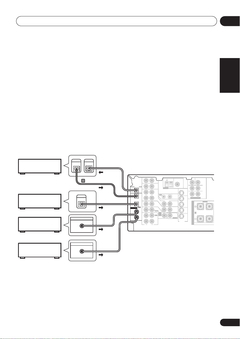
Connecting digital components
The easiest way to hook up this receiver for surround sound is to use a digital input. You can do
this by either coaxial or optical connections (you do not need to do both). The quality of these
two types of connections is the same but since some digital components only have one type of
digital terminal, it is a matter of matching like with like (for example, the coaxial output from the
component to coaxial input on the receiver). The VSX-D712 has three digital inputs on the rear
panel (two coaxial inputs and an optical input) and both the VSX-D812 and VSX-D912 have four
(two coaxial inputs and two optical inputs). Connect your digital components to the rear panel
as shown below.
There is one digital output jack which is marked
input on a digital recorder (currently these include MD, DAT and CD-R) you can make direct
digital recordings with this unit.
When connecting your equipment, always make sure the power is turned off and the power cord
is disconnected from the AC outlet.
• The arrows indicate the direction of the digital audio signal.
DIGITAL
CD recorder
Satellite tuner
CD player
DIGITAL
IN
OUT
VSX-D912/D812 only
DIGITAL
OUT
DIGITAL OUT
COAX
DIGITAL OUT
This receiver*
DIGITAL
OUT
OPT
OPT
2
(CD-R/TAPE/MD)
OPT
1
(TV/
SAT)
ASSIGNABLE
COAX
DIGITAL
2
IN
(CD)
COAX
1
(DVD
/LD)
. If you connect this to the optical
CEN-
OUT
VCR/
DVR
IN
TV/
SAT
IN
DVD/
LD
IN
SUB WOOFER
TER
SURROUND
LR
SURROUND
BACK
LR
DVD 7.1CH INPUT
RL
S
P
E
A
A
K
E
R
S
FRONT
AM
FM UNBAL
LOOP
Ω
ANTENNA
OUT IN
VIDEO
IN
IN
D V D
7.1CH
INPUT
IN
75
CONTROL
OUT
MONITOR
OUT
SUB
WOOFER
PREOUT
MONITOR OUT
S-VIDEO
AUX
IN
CD
IN
VCR/
OUT
DVR
IN
TV/
SAT
IN
DVD
/ LD
FRONT
IN
REC
CD-R
OUT
/ TAPE
/ MD
IN
PLAY
R
L
AUDIO
English Italiano Français
Nederlands
DVD player
*
The illustration shows the VSX-D812/D912, but connections for the VSX-D712 are the same.
DIGITAL OUT
COAX
EspañolDeutsch
17
En
Page 18
04
L
Connecting up
• If you have an LD player, you need to make special connections to ensure you can play 2
RF format LDs on your system. If this is the case, hook up your DVD or LD player directly to
an RF demodulator using both the
2
RF output and either a coaxial or optical digital
connection. We also recommend hooking up your digital components to analog audio jacks
as well. Make sure the RF demodulator digital in switch is set correctly (optical or coaxial
depending on the connection). See the component's instruction manual if you are unsure
about its input and output jacks.
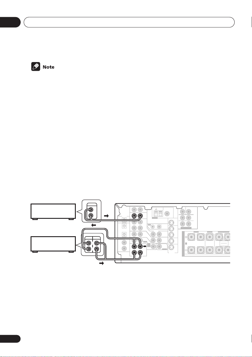
Connecting audio components
To begin set up, connect your analog audio components (such as a cassette deck) to the jacks.
For components you want to record with, you need to hook up four plugs to the receiver (a set
of stereo inputs and a set of stereo outputs), but for components that only play, you only need
to hook up one set of stereo plugs. You must also hook up your digital components to analog
audio jacks if you want to record to/from digital components (like an MD) to/from analog
components. See page 17 for more on digital connections.
When connecting your equipment, always make sure the power is turned off and the power cord
is disconnected from the AC outlet.
• The arrows indicate the direction of the audio signal.
18
En
CD player
OUTPUT
L
R
PLAY
CD-R/Tape/MD deck
REC
L
R
*
The illustration shows the VSX-D812/D912, but connections for the VSX-D712 are the same.
This receiver*
IN
DIGITAL
OUT
IN
OPT
OPT
OUT
2
(CD-R/TAPE/MD)
IN
OPT
1
(TV/
IN
SAT)
ASSIGNABLE
COAX
DIGITAL
2
IN
IN
(CD)
COAX
1
OUT
(DVD
/LD)
IN
R
AUDIO
AUX
CD
VCR/
DVR
TV/
SAT
DVD
/ LD
FRONT
REC
CD-R
/ TAPE
/ MD
PLAY
L
ANTENNA
OUT IN
VIDEO
IN
IN
D V D
7.1CH
INPUT
IN
CEN-
OUT
VCR/
DVR
IN
TV/
SAT
IN
DVD/
LD
IN
SUB WOOFER
TER
SURROUND
LR
SURROUND
BACK
LR
DVD 7.1CH INPUT
RL
S
P
E
A
A
K
E
R
S
FRONT
CENTER
AM
FM UNBAL
LOOP
Ω
75
MONITOR OUT
CONTROL
OUT
MONITOR
OUT
SUB
WOOFER
PREOUT
S-VIDEO
SURROUND BACK
R
SINGLE
SEE INSTRUCTION
MANUAL
Page 19
Connecting up
04
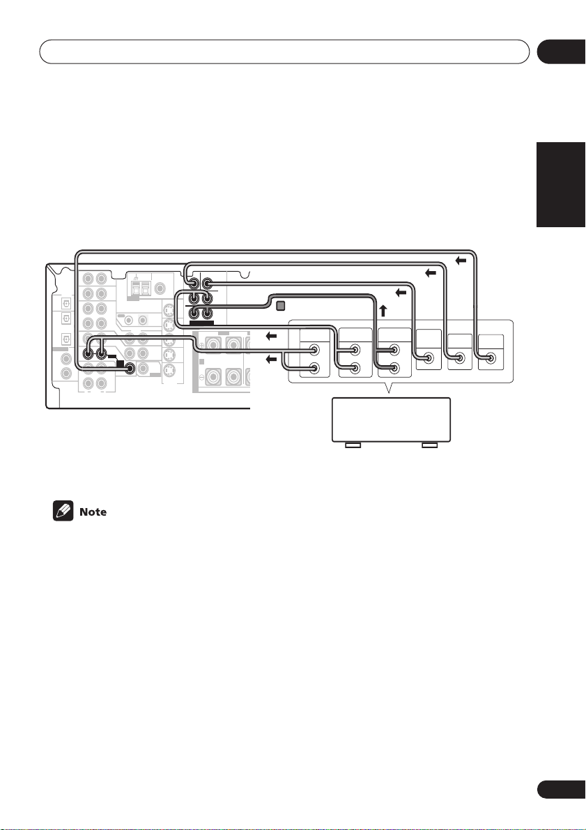
Connecting DVD multi-channel components
If you prefer to use a seperate component for decoding DVDs, you can connect a decoder or a
DVD player with multi-channel analog outputs to the multi-channel inputs of this receiver.
When connecting your equipment, always make sure the power is turned off and the power cord
is disconnected from the AC outlet.
• The arrows indicate the direction of the signal.
CEN-
AM
FM UNBAL
LOOP
75
DIGITAL
OUT
(CD-R/TAPE/MD)
ASSIGNABLE
COAX
DIGITAL
IN
COAX
AUX
IN
CD
IN
OPT
OPT
VCR /
OUT
DVR
2
IN
OPT
1
TV /
SAT
(TV /
IN
SAT )
DVD
/ LD
2
FRONT
IN
(CD)
REC
1
CD-R
OUT
(DVD
/ TAPE
/LD)
/ MD
IN
PLAY
R
L
AUDIO
ANTENNA
OUT IN
VIDEO
IN
IN
D V D
7.1CH
INPUT
IN
CONTROL
OUT
MONITOR
OUT
SUB
WOOFER
PREOUT
Ω
MONITOR OUT
S-VIDEO
This receiver*
* The illustration shows the VSX-D812/D912, but connections for the VSX-D712 are the same.
• The multi-channel input can only be used when DVD 5.1 ch (VSX-D712) or DVD 7.1 ch (VSXD812/D912) is selected (see page 42).
VSX-D812/D-912 only
• If the component you are connecting only has one surround back channel output, change
the Surround back channel input setting (page 48) to SB 1ch IN.
SUB WOOFER
TER
SURROUND
LR
SURROUND
BACK
LR
DVD 7.1CH INPUT
OUT
VCR/
DVR
DVD/
LD
FRONT
RL R
S
IN
P
E
TV/
SAT
A
IN
A
K
E
IN
R
S
PREOUT
SURROUND
LL
BACK
VSX-D812/D912 only
RR
SURROUND
FRONT CENTER
SURROUND BACK
RL
SINGLE
SEE INSTRUCTION
MANUAL
FRONT
OUTPUT
L
R
SURROUND
LR L
OUTPUT
DVD/multi-channel decoder
with multi-channel analog
output jacks
FRONTCENTER SURROUND
L
R
SURROUND
BACK OUTPUT
B
SUB
CENTER
WOOFER
OUTPUT
L
OUTPUT
VIDEO
OUTPUT
R
English Italiano Français
Nederlands
EspañolDeutsch
19
En
Page 20
04
C
Connecting up
Connecting video components
Connect your video components to the jacks as shown below. With digital video components
(like a DVD player), you must use the connections shown on this page for the video signal, but
in order to hear a digital source (like a DVD) you should hook up the audio to a digital input (see
page 17). It is also a good idea to hook up your digital components with analog audio
connections (see page 18).
For better quality video, you can hook up using the S-video jacks on the rear of the receiver
instead of the regular video jacks. Make sure they are connected to the video component using
the same kind of connection.
When connecting your equipment, always make sure the power is turned off and the power cord
is disconnected from the AC outlet.
• The arrows indicate the direction of the signal
Video deck
INPUT
VIDEO
L
R
LR
BACK
LR
CENTER SURROUND
FRONT
INPUT
VIDEO
TV tuner
(or Satellite tuner)
DVD or LD player
OUTPUT
VIDEO
OUTPUT
VIDEO
This receiver*
CEN-
AM
FM UNBAL
LOOP
Ω
ANTENNA
OUT IN
VIDEO
IN
IN
D V D
7.1CH
INPUT
IN
CONTROL
OUT
MONITOR
OUT
SUB
WOOFER
PREOUT
75
MONITOR OUT
S-VIDEO
L
R
L
DIGITAL
OUT
(CD-R/TAPE/MD)
ASSIGNABLE
DIGITAL
IN
CD
IN
OPT
OPT
VCR/
OUT
DVR
2
IN
OPT
1
TV/
SAT
(TV/
IN
SAT )
COAX
DVD
/ LD
2
FRONT
IN
(CD)
COAX
REC
1
CD-R
OUT
(DVD
/ TAPE
/LD)
/ MD
IN
PLAY
R
L
AUDIO
AUX
IN
R
SUB WOOFER
TER
SURROUND
SURROUND
DVD 7.1CH INPUT
OUT
VCR/
RL R
DVR
S
IN
P
E
TV/
SAT
A
IN
A
K
DVD/
LD
E
IN
R
S
OUTPUT
VIDEO
L
R
SURROUND BACK
RL
SINGLE
SEE INSTRUCTION
MANUAL
LL
RR
SURROUND
FRONT CENTER
PREOUT
SURROUND
BACK
L
TV (monitor)
*
The illustration shows the VSX-D812/D912, but connections for the VSX-D712 are the same.
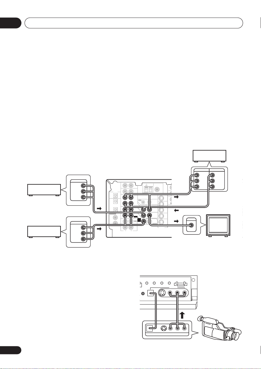
Connecting to the front panel video
terminal
Front video connections are accessed via the
front panel using the
standard audio/video jacks as well as an
S-video jack (the VSX-D912 also has an optical
VIDEO
button. There are
O/
SIGNAL
MIDNIGHT/
SPEAKERS
T
SELECT
LOUDNESS
SETUP
DIGITAL IN
MIC
S-VIDEO VIDEO L AUDIO R
input). Hook them up the same way you made
the rear panel connections.
DIGITAL OUT
SB CH
TONE
MODE
MULTI JOG
VIDEO INPUT
LV
VIDEO OUTPUT
QUICK
SETUP
Video
camera
(etc.)
R
20
En
Page 21
Connecting up
04
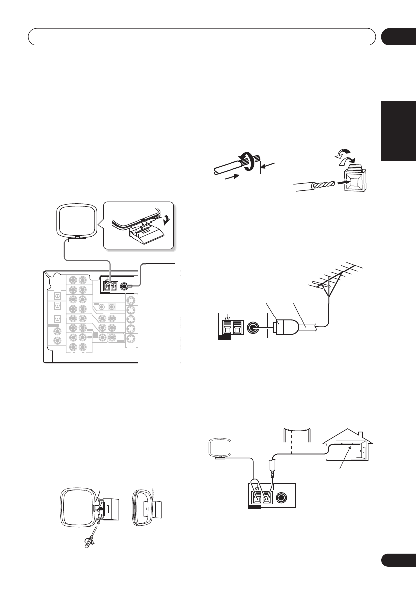
Connecting antennas
Connect the AM loop antenna and the FM
wire antenna as shown below. To improve
reception and sound quality, connect external
antennas (see
below). Always make sure that the receiver is
switched off and unplugged from the wall
outlet before making or changing any
connections.
(CD-R/TAPE/MD)
ASSIGNABLE
DIGITAL
IN
FM wire antenna
Connect the FM wire antenna and fully extend
vertically along a window frame or another
suitable place that gives good reception.
AM loop antenna
Assemble the antenna and connect to the
receiver. Attach (if necessary) and face in the
direction that gives the best reception.
Using external antennas
AM loop
antenna
AUX
IN
DIGITAL
OUT
CD
IN
OPT
OPT
OUT
2
IN
OPT
1
(TV/
IN
SAT)
COAX
2
IN
(CD)
COAX
1
OUT
(DVD
/LD)
IN
ANTENNA
VCR/
OUT IN
DVR
VIDEO
IN
TV/
SAT
IN
DVD
/ LD
FRONT
D V D
7.1CH
INPUT
REC
IN
CD-R
/ TAPE
/ MD
PLAY
R
L
AUDIO
FM wire
CEN-
OUT
VCR/
DVR
IN
TV/
SAT
IN
DVD/
LD
IN
SUB WOOFER
TER
antenna
SURROUND
LR
SURROUND
LR
DVD 7.1CH INPUT
RL
S
P
E
A
A
K
E
R
S
BACK
FRONT
AM
FM UNBAL
LOOP
75
Ω
MONITOR OUT
CONTROL
OUT
MONITOR
OUT
SUB
WOOFER
PREOUT
S-VIDEO
Antenna snap connectors
Twist the exposed wire strands together and
insert into the hole, then snap the connector
shut.
10mm
Using external antennas
To improve FM reception
Connect an external FM antenna.
FM UNBAL
75
Ω
Outdoor
antenna
75Ω coaxial
cable
AM
FM UNBAL
LOOP
75
Ω
5–6m
Indoor antenna
(vinyl-coated wire)
One-touch
PAL connector
AM
LOOP
ANTENNA
To improve AM reception
Connect a 5–6 metre length of vinyl-coated
wire to the AM antenna terminal without
disconnecting the supplied AM loop antenna.
For the best possible reception, suspend
horizontally outdoors.
English Italiano Français
Nederlands
EspañolDeutsch
ANTENNA
21
En
Page 22
04
OOP
UNBAL
OUT
edwoofer
Connecting up
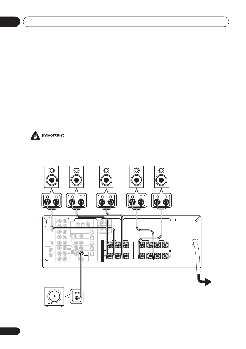
Connecting the speakers (VSX-D712)
A complete setup of six speakers (including the subwoofer) is shown below, but everyone’s
home setup will vary. Simply connect the speakers you have in the manner shown below. The
receiver will work with just two stereo speakers (the front speakers in the diagram) but using at
least three speakers is recommended, and a complete setup is best. If you’re not using a
subwoofer, change the front speaker setting (see
Make sure you connect the speaker on the right to the right terminal and the speaker on the left
to the left terminal. Also make sure the positive and negative (
match those on the speakers.
Be sure to complete all connections before connecting this unit to the AC power source.
Speaker setting
+/–
on page 44) to large.
) terminals on the receiver
• Use speakers with a nominal impedance of 8
Front speakers
LR C LSRS
L
MONITOR OUT
SURROUND
CONTROL
OUT
MONITOR
OUT
SUB
WOOFER
PREOUT
SURROUND
BACK
S-VIDEO
DVD 5.1CH INPUT
OUT
VCR/
DVR
DVD/
LD
FRONT
RL R LRL
S
IN
P
E
TV/
SAT
A
IN
A
K
E
IN
R
S
ASSIGNABLE
DIGITAL
IN
VCR/
OUT
OUT IN
DVR
IN
OPT
1
(TV/
IN
SAT )
COAX
2
IN
(CD)
COAX
1
OUT
(DVD
/LD)
IN
R
VIDEO
IN
TV/
SAT
IN
DVD
/ LD
FRONT
D V D
5.1CH
INPUT
REC
IN
CD-R
/ TAPE
/ MD
PLAY
L
AUDIO
Power
Ω
to 16 Ω.
Surround speakersCenter speaker
FRONTCENTER SURROUND
B
VSX-D712
22
En
Page 23
Connecting up
S
R
CEN-
UX
OUT
SURROUND
edwoofer
g
d
r
04
Connecting the speakers (VSX-D812/D912)
A complete setup of eight speakers (including the subwoofer) is shown below, but everyone’s
home setup will vary. Simply connect the speakers you have in the manner shown below. The
receiver will work with just two stereo speakers (the front speakers in the diagram) but using at
least three speakers is recommended, and a complete setup is best for surround sound. If
you’re not using a subwoofer, change the front speaker setting (see
to large.
Make sure you connect the speaker on the right to the right terminal and the speaker on the left
to the left terminal. Also make sure the positive and negative (
match those on the speakers.
Be sure to complete all connections before connecting this unit to the AC power source.
• Use speakers with a nominal impedance of 8
Front speakers
LR C LSRS
DIGITAL
(CD-R/TAPE/MD)
ASSIGNABLE
DIGITAL
IN
A
OUT
CD
IN
OPT
OPT
VCR/
OUT
OUT IN
DVR
2
IN
OPT
(TV/
SAT)
COAX
(CD)
COAX
(DVD
/LD)
IN
1
TV/
SAT
IN
IN
DVD
/ LD
2
FRONT
IN
D V D
7.1CH
INPUT
REC
1
IN
CD-R
OUT
/ TAPE
/ MD
IN
PLAY
R
L
AUDIO
ANTENNA
CONTROL
VIDEO
OUT
MONITOR
OUT
SUB
WOOFER
PREOUT
Center speaker
UB WOOFE
SURROUND
MONITOR OUT
S-VIDEO
LR
SURROUND
BACK
LR
DVD 7.1CH INPUT
OUT
VCR/
FRONT
RL R
DVR
S
IN
P
E
TV/
SAT
A
IN
A
K
DVD/
LD
E
IN
R
S
Ω
to 16 Ω.
Surround speakers
BACK
RR
FRONT CENTER
SURROUND
SURROUND BACK
RL
SINGLE
SEE INSTRUCTION
MANUAL
LR L
VSX-D812/D912
Passive
Power
subwoofer
or sin
le
rroun
TV
k
speake
Speaker setting
+/–
) terminals on the receiver
on page 44)
Surround back speakers
SBL SBR
FRONTCENTER SURROUND
B
English Italiano Français
Nederlands
EspañolDeutsch
23
En
Page 24
04
Connecting up
• When using the speaker on your TV as the
center speaker (
PREOUT
input jack on your TV. In this case the
center speaker shown is unnecessary.
• If you are using only one surround back
speaker, connect the positive wire to the
right channel (
negative wire to the left channel (
terminal (see illustration on page 11).
• If you select subwoofer (
Surround back speaker setting
you can hook up a subwoofer instead of
speakers to the surround back speaker
terminals. Connect the positive wire to the
right channel (
negative wire to the left channel (
terminal (see illustration on page 11).
C
), connect the
jack on this unit to the audio
+
) terminal, and the
+
) terminal, and the
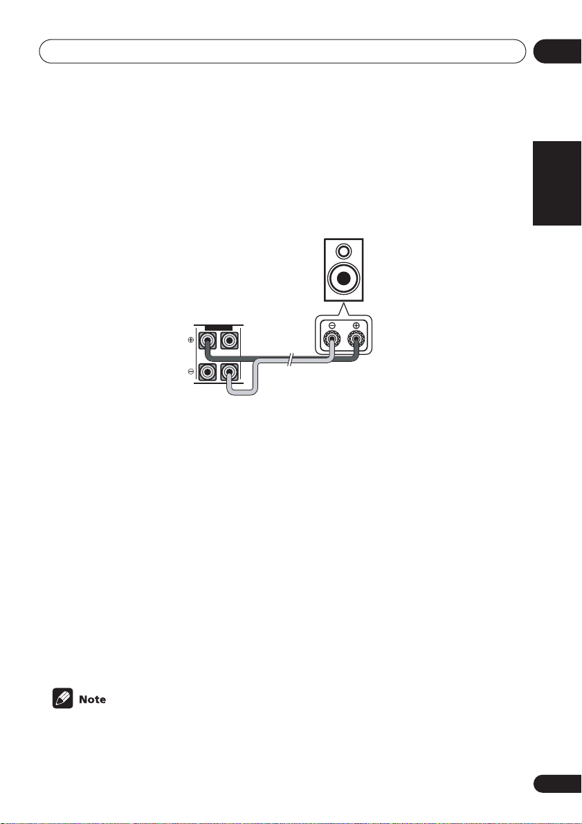
Speaker terminals
12 3
10mm
1 Twist exposed wire strands together.
2 Loosen speaker terminal and insert
exposed wire.
Make sure that all the bare speaker wire is
twisted together and inserted fully into the
speaker terminal. If any of the bare speaker
wire is touching the back panel when you
switch the unit on, the power may cut off as a
safety measure. Use good quality speaker
wire to connect the speakers to the receiver.
3 Tighten terminal.
SB SW
on page 45
CENTER
–
)
) in the
–
)
A and B speaker systems
The receiver has two speaker systems: A and
B. A is the main system supporting the full
speaker setup. If you switch on both A and B
speaker systems, only the front speakers and
the (active) subwoofer will be audible. No
sound will come from the center, surround, or
surround back speakers, but multi-channel
sources will be down-mixed to the active
speakers so no sound will be lost. Similarly, if
you choose just the B system you‘ll only hear
the front speakers connected to the B system
and multi channel sources will be downmixed to these two speakers.
• Press the SPEAKERS button on the
front panel to switch between speaker
systems (A, B or both).
Hints on speaker placement
Speakers are usually designed with a
particular placement in mind. Some are
designed to be floorstanding, while others
should be placed on stands to sound their
best. Some should be placed near a wall;
others should be placed away from walls. We
have provided a few tips on getting the best
sound from your speakers (following), but you
should also follow the guidelines on
placement that the speaker manufacturer
provided with your particular speakers to get
the most out of them.
• Place the front left and right speakers at
equal distances from the TV.
• When placing speakers near the TV, we
recommend using magnetically shielded
speakers to prevent possible interference,
such as discoloration of the picture when
the TV is switched on. If you do not have
magnetically shielded speakers and
notice discoloration of the TV picture,
move the speakers farther away from the
TV.
24
En
Page 25
Connecting up
04
• Place the center speaker above or below
the TV so that the sound of the center
channel is localized at the TV screen.
• If possible, place the surround speakers
slightly above ear level.
• Try not to place the surround speakers
further away from the listening position
than the front and center speakers. Doing
so can weaken the surround sound effect.
• To achieve the best possible surround
sound, install your speakers as shown
below. Be sure all speakers are installed
securely to prevent accidents and
improve sound quality.
• If you choose to install the center speaker
on top of the TV, be sure to secure it with
putty, or by other suitable means, to
reduce the risk of damage or injury
resulting from the speaker falling from the
TV in the event of external shocks such as
earthquakes.
Overhead view of speaker setup
Front
Left
Surround
Left
Listening Position
Surround Back Surround Back
3-D view of
Left Right
Single Surround Back Speaker
6.1 channel
Front
RightCenter
Subwoofer
Surround
Right
speaker setup
English Italiano Français
Nederlands
3-D view of
7.1 channel
speaker setup
EspañolDeutsch
25
En
Page 26
04
Connecting up
Connecting additional amplifiers
This receiver has more than sufficient power for any home use, however it is possible to add
additional amplifiers to every channel on the VSX-D812/D912 or the surround back channel of
the VSX-D712. Make the connections shown below to add amplifiers to power your speakers.
Always make sure that the receiver is switched off and unplugged from the wall outlet before
making or changing any connections.
• The arrows indicate the direction of the audio signal.
VSX-D712
CEN-
MONITOR OUT
S-VIDEO
SUB WOOFER
TER
LR
SURROUND
DVD 5.1CH INPUT
OUT
VCR/
DVR
IN
TV/
SAT
IN
DVD/
LD
IN
FRONT
RL R LRL
S
P
E
A
A
K
E
R
S
INPUT
ANALOG IN
FRONTCENTER SURROUND
B
Surround back
channel amplifier
or powered speaker
ASSIGNABLE
DIGITAL
IN
DIGITAL
OUT
AM
FM UNBAL
LOOP
Ω
ANTENNA
OUT IN
VIDEO
IN
IN
D V D
5.1CH
INPUT
IN
75
CONTROL
OUT
MONITOR
OUT
SUB
WOOFER
PREOUT
SURROUND
BACK
AUX
IN
CD
IN
OPT
VCR/
OUT
DVR
IN
OPT
1
TV/
SAT
(TV/
IN
SAT )
COAX
DVD
/ LD
2
FRONT
IN
(CD)
COAX
REC
1
CD-R
OUT
(DVD
/ TAPE
/LD)
/ MD
IN
PLAY
R
L
AUDIO
Powered
subwoofer
26
En
VSX-D812/D912
OPT OPT
AUX
IN
DIGITAL
(
(
CD-R/
TV/
OUT
¥
ø
)
CD
SAT
IN
/ TAPE
OPT
)
/ MD
OPT
VCR/
OUT
DVR
2
(CD-R/TAPE/MD)
IN
OPT
RL
S
1
TV/
SAT
(TV/
P
IN
SAT)
ASSIGNABLE
DIGITAL
IN
E
COAX
DVD
/ LD
2
A
FRONT
IN
(CD)
A
K
COAX
REC
1
E
CD-R
OUT
(DVD
/ TAPE
/LD)
R
/ MD
S
IN
PLAY
R
L
AUDIO
AM
FM UNBAL
LOOP
75
Ω
COMPONENT
ASSIGNABLE
ASSIGNABLE
VIDEO
COMPONENT
12
VIDEO
MONITOR OUT
DIGITAL OUT
ANTENNA
MONITOR OUT
MONITOR OUT
OUT IN
YPBPRYP
BPR
YP
P
CONTROL
VIDEO
FRONT
CENTER
SURROUND BACK
R
OUT
MONITOR
OUT
SUB
WOOFER
PREOUT
R
S-VIDEO
IN
IN
D V D
7.1CH
INPUT
IN
LL
B
B
RR
FRONT CENTER
SURROUND
OUT
VCR/
R
RL
DVR
IN
TV/
SAT
SINGLE
IN
IN
SEE INSTRUCTION
MANUAL
DVD/
LD
IN
PREOUT
SURROUND
BACK
FRONTSURROUND
LR L
B
ANALOG IN
L R
ANALOG IN
R
L
ANALOG IN
ANALOG IN
INPUT
Powered
subwoofer
Front channel
amplifier
Surround channel
amplifier
Surround back
channel amplifier
Center channel
amplifier
Page 27
Connecting up
04
• To hear sound only from the pre-outs,
disconnect any speakers that are
connected directly to the receiver.
• If you’re not using a subwoofer, change
the front speaker setting (see
setting
on page 44) to large.
•
VSX-D712 only –
If you connect to a
Speaker
surround back speaker, make sure the
Surround back speaker setting
on page 45
is switched on and set to the proper
speaker size.
• These speaker terminals are hazardous
when live. To prevent the risk of electric
shock when connecting or disconnecting
the speaker cables, disconnect the power
cord.
Power cord caution
Handle the power cord by the plug. Do not
pull out the plug by tugging the cord and
never touch the power cord when your hands
are wet as this could cause a short circuit or
an electric shock. Do not place the unit, a
piece of furniture, etc., on the power cord, or
pinch the cord. Never make a knot in the cord
or tie it with other cords. The power cords
should be routed such that they are not likely
to be stepped on. A damaged power cord can
cause a fire or give you an electrical shock.
Check the power cord once in a while. When
you find it damaged, ask your nearest Pioneer
authorized service center or your dealer for a
replacement.
Operating other Pioneer
components
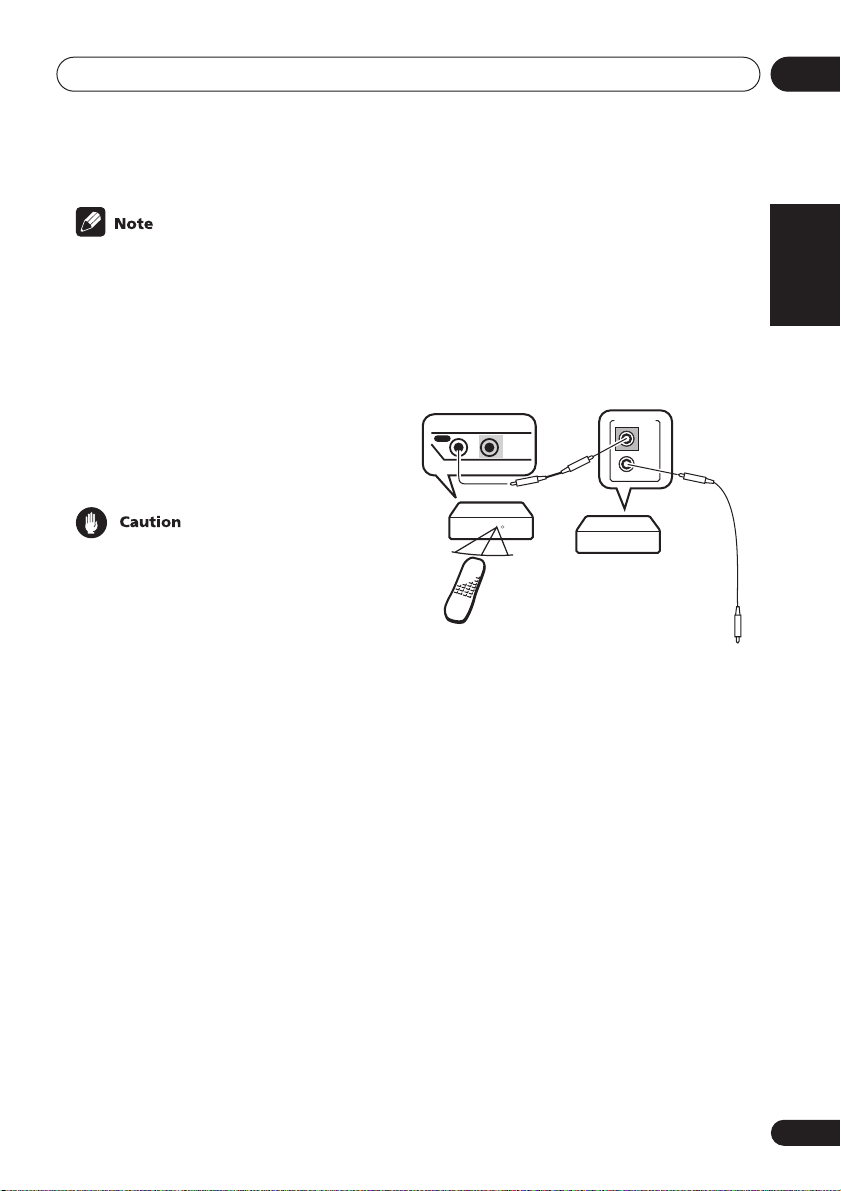
By connecting a control cord (optional), you
can point the remote controls of other Pioneer
components at the receiver’s remote sensor.
The remote control signals are received by the
remote sensor of this unit, and sent to the
other devices via the
of the receiver.
OUT IN
CONTROL
Receiver
Remote
control
unit
CONTROL OUT
CONTROL
IN
OUT
Other Pioneer products
with CONTROL terminals
Connect to CONTROL
terminal of other
compatible Pioneer products
terminal
English Italiano Français
Nederlands
EspañolDeutsch
27
En
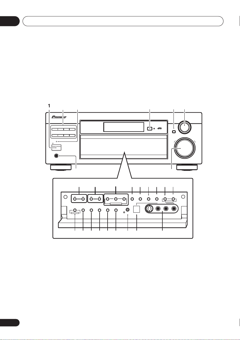
Page 28
05
O
Controls and displays
Chapter 5:
Controls and displays
Front panel
DVD/LDTV/SATVCR/DVRVIDE
CD-R/
CD
AUX
TAPE/MD
TUNER
STANDBY
STANDBY/ON
PHONES
8
10 11 12 13 14 15 16 17
9
STATION STANDARD SPEAKERS
TUNING
TUNER EDIT
MULTI JOG
BAND
CLASS
ADVANCED
SURROUND
PHONES SURR.
LISTENING MODE
PTY
EON
MPX
SEARCH
MODE
26 25 24 23 22 21 18
1 STANDBY/ON
Switches the receiver between on and
standby.
2 Input select buttons
Press to select an input source.
3 STANDBY indicator
Lights when the receiver is in standby.
4 Remote sensor
Receives the signals from the remote control.
4
5 6
ENTER
DOWN UP
MULTI JOG
MASTER VOLUME
7
STEREO/
SIGNAL
MIDNIGHT/
DIRECT
SELECT
LOUDNESS
SETUP
DIGITAL IN
MIC
SB CH
TONE
MODE
MULTI JOG
VIDEO INPUT
S-VIDEO VIDEO L AUDIO R
QUICK
SETUP
1920
5 ENTER
6 MULTI JOG dial
The
MULTI JOG
dial performs a number of
tasks. Use it to select options after pressing
TONE, QUICK SETUP
or
TUNER EDIT
7 MASTER VOLUME
8 PHONES jack
Use to connect headphones. When the
headphones are connected, there is no sound
output from the speakers.
.
28
En
Page 29

Controls and displays
05
9 STATION +/– buttons
Selects station presets when using the tuner
(page 55).
10 TUNING +/– buttons
Selects the frequency when using the tuner
(page 52).
11 LISTENING MODE buttons
STANDARD
Press for Standard decoding and to
switch between the various Pro Logic II
and Neo:6 options (page 37).
ADVANCED SURROUND
Use to switch between the various
surround modes
STEREO/DIRECT
Switches between direct and stereo
playback. Direct playback bypasses the
tone controls and channel levels for the
most accurate reproduction of a source
(page 38).
12 SIGNAL SELECT
Use to select an input signal (page 36).
13 MIDNIGHT/LOUDNESS
Use Midnight when listening to movie
soundtracks at low volume. Use Loudness to
boost the bass and treble at low volume
(page 41).
14 SPEAKERS
Use to cycle through the speaker system:
A B A+B
15 SB CH MODE
Selects the Surround back channel mode
(page 39) and the Virtual Surround Back
(VSB) mode (page 40).
16 TONE
Press this button to access the bass and
treble controls, which you can then adjust
with the
(page 24)
MULTI JOG
(page 38).
dial (page 41).
17 QUICK SETUP
See
Using the Quick Setup
18 VIDEO INPUT
See
Connecting to the front panel video
terminal
19 DIGITAL IN
VSX-D912 only
See
terminal
20 SETUP MIC
VSX-D912 only
Connect the microphone supplied with your
system to the
auto surround setup (MCACC)
21 EON MODE
Use to search for different programs that are
transmitting traffic or news information (this
search method is called EON) (page 57).
22 PTY SEARCH
Use to search for different program types in
RDS mode (page 56).
23 MPX
Press to receive a radio broadcast in mono
(page 52).
24 BAND
Switches between AM and FM radio bands
(page 52).
25 CLASS
Switches between the three banks (classes)
of station presets
26 TUNER EDIT
Press to memorize and name a station for
recall
on page 20.
Connecting to the front panel video
on page 20.
SETUP MIC
(page 53).
(page 53).
on page 12.
jack when using the
(page 14).
English Italiano Français
Nederlands
EspañolDeutsch
29
En
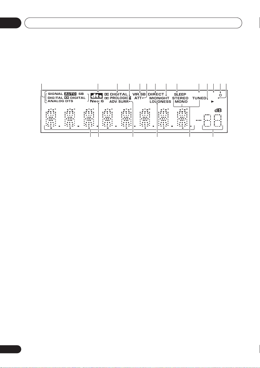
Page 30
05
4
Controls and displays
Display
1234576 1
15
16 19
1 SIGNAL SELECT indicators
Lights to indicate the type of input signal
assigned for the current component:
AUTO
Lights when
AUTO
signal select is on.
SB
Depending on the source, this lights
when a signal with surround back
channel encoding is detected.
DIGITAL
Lights when a digital audio signal is
detected.
2
DIGITAL
Lights when a Dolby Digital encoded
signal is detected.
ANALOG
Lights when an analog signal is detected.
DTS
Lights when a source with DTS encoded
audio signals is detected.
2 DTS
When the
STANDARD
mode of the receiver is
on, this lights to indicate decoding of a DTS
signal.
17
3
When the
on, this lights to indicate decoding of a Dolby
Digital signal.
4
When the (
the receiver is on, this lights to indicate Pro
Logic II decoding.
5 VIR.SB
Lights during Virtual surround back
processing.
6 ATT
Lights when
(reduce) the level of the analog input signal.
7 DIRECT
Lights when source direct playback is in use.
Direct playback bypasses the tone controls
and channel levels for the most accurate
reproduction of a source.
8 MIDNIGHT
Lights during Midnight listening.
9 SLEEP
Lights when the receiver is in sleep mode.
10 RF ATT
89 10 12 1311
2
DIGITAL
STANDARD
2
PRO LOGIC II
STANDARD
INPUT ATT
RFATT EON
mode of the receiver is
) Pro Logic II mode of
is used to attenuate
Lights when the RF attenuator is on (page 52).
RDS
SP A B
2018
30
En
Page 31

Controls and displays
05
11 Speaker indicator
Shows the speaker system currently in use.
12 EON
When the EON mode is set. the
lights, but during actual reception of an EON
broadcast the
13 indicator
The indicator lights to inform you that the
currently tuned station carries the EON data
service.
14 RDS
Lights when an RDS broadcast is received.
15 Character display
16 Neo:6
When the (
receiver is on, this lights to indicate NEO:6
processing.
17 ADV.SURR. (Advanced Surround)
Lights when one of the Advanced Surround
modes has been selected.
18 LOUDNESS
Lights when
19 TUNER indicators
STEREO
Lights when a stereo FM broadcast is
being received in auto stereo mode.
MONO
Lights when the mono mode is set using
the
TUNED
Lights when a broadcast is being
received.
20 Master volume level
Shows the overall volume level.
indicates the minimum level, and
indicates the maximum level.
STANDARD
LOUDNESS
MPX
button.
EON
indicator will flash.
EON
indicator
) NEO:6 mode of the
has been selected.
---dB
- 0 dB
Depending on your level settings for each
channel, the maximum volume can range
between –10 dB and –0 dB.
English Italiano Français
Nederlands
EspañolDeutsch
31
En
Page 32

05
0
4
Controls and displays
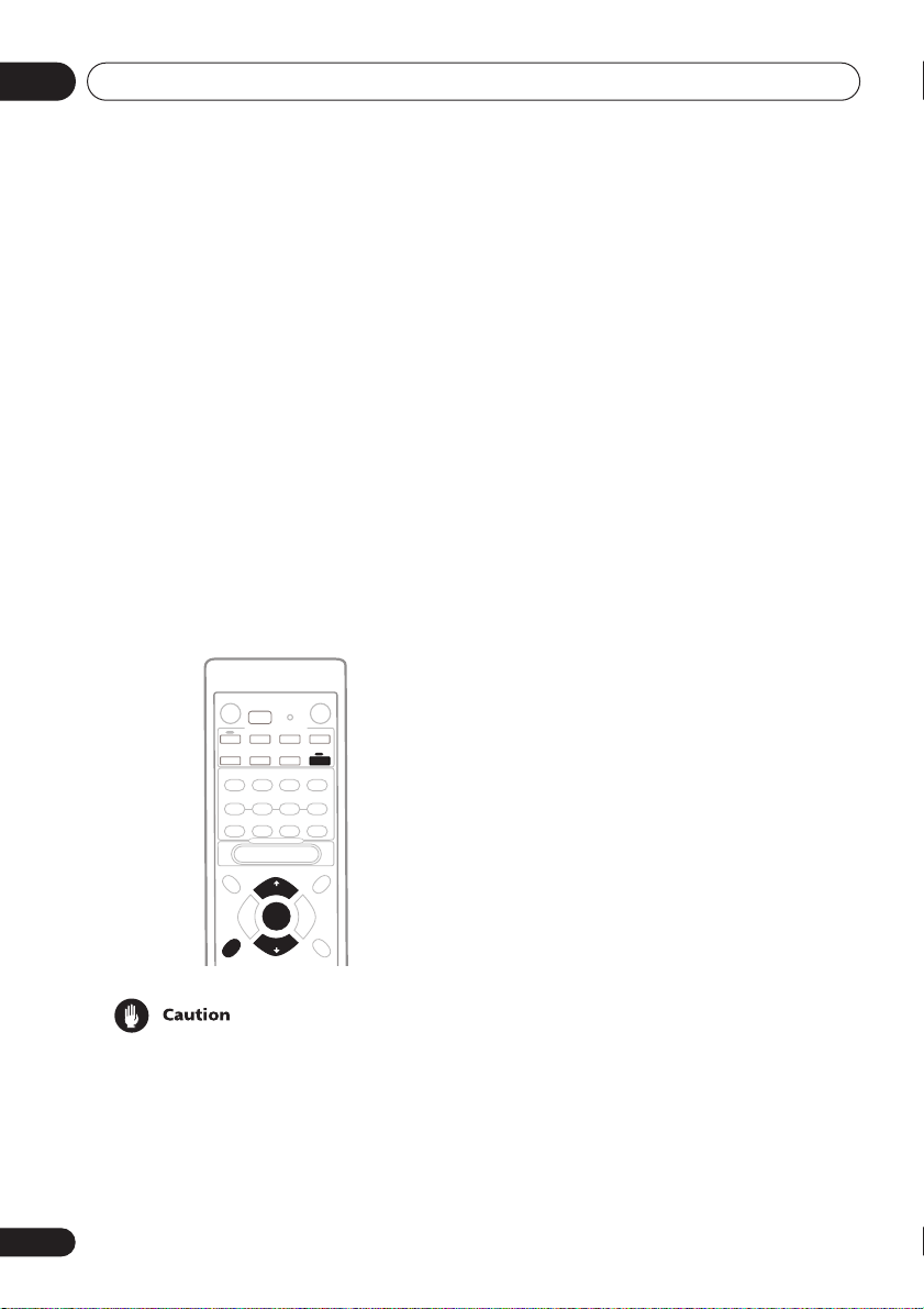
Remote control
1
RECEIVER
TEST
TONE
FL
INPUT ATT
T.EDIT
GUIDE
SUBTITLE
RF ATT
DISC
ENTER
+
10
11
12
5
13
1
on
RECEIVER
1
DVD/LD
2
STANDARD
3
4
TOP MENU MENU
5
6
AUDIO
DISPLAY CLASS MPX D.ACCESS
7
CD
CH
SELECT
MUTE
INPUT SELECT
TV/SAT
CD-R/TAPE
ADVANCED
SURROUND
ST
MCACC
SETUP
MULTI CONTROL
RECEIVER CONTROL
LEVEL
EFFECT
MASTER
VOLUME
SETUP
TUNE
ENTER
TUNE
BANDRETURN
SOURCE
VCR/DVR TV CONT
TUNER
STEREO/
MIDNIGHT/
DIRECT
LOUDNESS
DIMMER
ST
SLEEP
A
EDCB
123
8
9
456
7890
TV CONTROL
INPUT
ECT
SEL
RECEIVER
CHANNEL VOLUME
CHANNEL
1 RECEIVER
This switches between standby and on for this
receiver.
2 MULTI CONTROL buttons
Press to select control of other components
(see
Controlling the rest of your system
page 60).
RECEIVER
Switches the remote to control the
receiver (used to select the features such
as
SLEEP, MCACC SETUP
, etc). Also use
this button to set up surround sound
(page 43, page 49).
3 RECEIVER CONTROL buttons
STANDARD
Press for Standard decoding and to
switch between the various Pro Logic II
and Neo:6 options (page 37).
ADVANCED SURROUND
Use to switch between the various
surround modes
(page 38).
STEREO/DIRECT
Switches between direct and stereo
playback. Direct playback bypasses the
tone controls and channel levels for the
most accurate reproduction of a source
(page 38).
MIDNIGHT/LOUDNESS
Switches to Midnight or Loudness
listening
(page 41).
CH SELECT
Selects a speaker when setting up the
surround sound of the receiver
(page 51).
LEVEL +/–
Adjusts the levels of the surround sound
of the receiver
(page 51).
TEST TONE
Sounds the test tone when setting up the
surround sound of the receiver
(page 51).
MUTE
Mutes the sound (or restores the sound if
it has been muted).
EFFECT +/–
Adds or subtracts the amount of effect
with different advanced surround modes
(page 38).
32
En
Page 33

Controls and displays
05
FL DIMMER
Dims or brightens the display.
4 MASTER VOLUME +/–
Use to set the listening volume.
5 Receiver and component control
buttons
CONTROL
These controls function according to the
component you’ve selected.
(Press the corresponding
button first to access).
TOP MENU
Displays the disc ‘top’ menu of a DVD.
AUDIO
Changes the audio language or channel
with DVD discs.
MCACC SETUP
Use to setup your speaker system using
the multi-channel acoustic calibration
system.
MENU
Displays the disc menu of DVD-Video
discs. It also displays TV and DTV menus.
INPUT ATT
Attenuates (lowers) the level of an analog
input signal to prevent distortion.
T.EDIT
Use to memorize and name a station for
recall using the
(page 53).
GUIDE
Displays the guides on a digital TV.
SUBTITLE
Displays/changes the subtitles included
in multilingual DVD-Video discs.
SLEEP
Use to put the receiver in sleep mode and
select the amount of time before the
receiver turns off.
STATION +/–
MULTI
buttons
6
Use the arrow buttons when setting up
your surround sound system (see
page 43). Also used to control DVD
menus/options and for deck 1 of a double
cassette deck player. Use the
buttons to find radio frequencies and use
ST +/–
7 Component/Tuner control buttons
The main buttons (, , etc.) are used to
control a component after you have selected
it using the
tuner/DTV controls above these buttons can
be accessed after you have selected the
corresponding
(
TUNER
DTV)).
RETURN
Returns to the last screen selected when
using a digital TV tuner.
BAND
Switches between the tuner AM and FM
bands
RF ATT
Use to lower the input level of a radio
signal that is too powerful or contains
interference that causes the sound to
distort (page 52).
DISPLAY
Use to switch the display between the
station preset name, frequency and RDS
data when using the tuner.
CLASS
Switches between the three banks
(classes) of radio station presets
(page 53).
MPX
Switches between stereo and mono
reception of FM broadcasts. If the signal
is weak then switching to mono will
improve the sound quality
(TUNE +/–, ST +/–) /ENTER
to find preset stations (page 55).
MULTI CONTROL
MULTI CONTROL
or
TV/SAT
(when connected to
(page 52).
TUNE +/–
buttons. The
button
(page 52).
English Italiano Français
Nederlands
EspañolDeutsch
33
En
Page 34

05
Controls and displays
D.ACCESS
After pressing, you can access a radio
station directly using the number buttons
(page 52).
8 Number buttons
Use the number buttons to directly select a
radio frequency (page 52) or the tracks on a
CD, DVD, etc.
9 CHANNEL +/–
Use to select channels when using a VCR,
DVR, etc.
10 INPUT SELECT
Use to select the input source.
11 LED
This lights when a command is sent from the
remote control.
12 SOURCE
Press to turn on/off other components
connected to the receiver.
13 DISC (ENTER)
The button’s use depends on the component
selected. It can be used to enter commands
for TV or DTV, and can also be used to select
a disc in a multi-CD player.
14 TV CONTROL buttons
These buttons are dedicated to control the TV
assigned to the
only have one TV to hook up to this system
assign it to the
button. If you have two TVs, assign the main
TV to the
Use to turn on/off the power of the TV.
(TV CONTROL) INPUT SELECT
Use select the TV function.
CHANNEL +/–
Use to select channels.
VOLUME +/–
Use to adjust the volume on your TV.
TV CONT
TV CONT MULTI CONTROL
TV CONT
button. Thus if you
button.
34
En
Page 35

Playing sources
06
Chapter 6:
Playing sources
Introduction to Sound Modes
There are three basic sound options: Stereo/
Direct (
STEREO/DIRECT
DARD
) or Advanced Surround (
SURROUND
).
Stereo/Direct
When you select
hear the source through just the front left and
right speakers (and possibly your subwoofer
depending on your speaker settings). Dolby
Digital and DTS multichannel sources are
downmixed to stereo.
In
STEREO
surround settings and you can still use the
Midnight, Loudness, and Tone control functions.
With
surround settings so that the audio remains
as close to the source audio signal as
possible.
• If you switch on Midnight listening, Loud-
, you’ll hear the audio with your
DIRECT
, you will bypass all effects and
ness, or the Tone controls when
selected, the receiver automatically
switches to
STEREO
Standard mode
The Standard mode can be used to decode
Dolby Digital, DTS, and Dolby Surround
sources.
The other surround sound options (next
column) can add multi-channel sound to
regular stereo sources.
STEREO
), Standard (
ADVANCED
or
DIRECT
.
STAN-
, you will
DIRECT
You can identify Dolby Digital software by the
1
Surround software is marked
unmarked software may also incorporate
Dolby Surround. Depending on the source
and the sound mode you have selected, you
may not get sound from the surround back
speakers in your setup. For more on this, refer
to
on page 40 and
Channel (SB CH)
Choose one of the following to add depth to a
2 channel source:
Pro Logic II Movie (MOVIE)
This mode gives 5.1 channel surround sound.
It is suitable for movies, especially those
recorded in Dolby Surround. The channel
separation and movement of surround effects
is comparable to Dolby Digital 5.1.
Pro Logic II Music (MUSIC)
This mode gives 5.1 channel surround sound
and is suitable for music. The surround effect
is more enveloping than Pro Logic II Movie.
is
Pro Logic (PROLOGIC)
This mode gives 4.1 channel surround sound.
It is less sensitive to the quality of the source
material, so may be useful when Pro Logic II
Movie/ Music modes don’t give good results.
Neo:6 Cinema (CINEMA)
This mode gives 6.1 channel surround sound
and is suitable for movies. The Neo:6 Cinema
mode delivers good channel separation for
movie soundtracks.
or marks. Most Dolby
3
Using the Virtual Surround Back mode (VSB)
Using the Surround Back
on page 39.
, but
English Italiano Français
Nederlands
EspañolDeutsch
35
En
Page 36

06
Playing sources
Neo:6 Music (MUSIC)
This mode gives 6.1 channel surround sound
and is suitable for music. The Neo:6 Music
mode plays the stereo source as is through
the front left/right speakers, and generates a
natural, ambient surround and center sound.
Advanced Surround modes
These are designed to be used with multichannel surround sound audio/visual
sources (like DVDs and LDs). Most Advanced
Surround modes are designed to be used with
film soundtracks, but some modes are also
suited for music sources. Try different
settings with various soundtracks to see
which you like.
• Depending on the source and the sound
mode you have selected, you may not get
sound from the surround back speakers
in your setup. For more on this, refer to
Using the Virtual Surround Back mode
(VSB)
on page 40 and
Back Channel (SB CH)
Advanced Movie (ADV. MOVIE)
Simulates the relaxed environment of a movie
theater, and is suitable for watching movies.
Advanced Music (ADV. MUSIC)
Simulates the acoustic environment of a large
concert hall and is suitable for music or
musical sources.
TV Surround (TV. SURR.)
This mode produces surround sound for both
mono and stereo TV sources. It is useful for
older movies recorded with mono
soundtracks.
Using the Surround
on page 39.
Sports (SPORTS)
This is designed for sports programs with alot
of action, adding to the excitement by
bringing background action to the forefront.
Game (GAME)
Useful when playing video games. It works
especially well with sound moving from left to
right in game software with alot of movement.
Expanded (EXPANDED)
This mode is especially designed to give
sound depth to stereo sources, and lets you
hear two-channel (stereo) signals as simulated multi-channel surround sound. Use with
Dolby Pro Logic for a stereo surround effect.
You can also use with Dolby Digital sources
for a wider stereo field than the
STANDARD
modes.
6-Channel Stereo (6-STEREO)
This can be selected to give multi-channel
sound to a stereo source, using all of the
speakers in your setup.
Phones Surround (PHONES SURROUND)
When listening through headphones, you can
still get the effect of overall surround.
Choosing the input signal
• Default setting:
You need to hook up a component to both
analog and digital inputs on the rear of the
receiver to select between input signals.
ADVANCED
STEREO/
SURROUND
STANDARD SPEAKERS
PHONES SURR.
LISTENING MODE
PTY
EON
SEARCH
MODE
AUTO
SIGNAL
MIDNIGHT/
DIRECT
SELECT
LOUDNESS
VIDEO INPUT
SETUP
DIGITAL IN
MIC
S-VIDEO VIDEO L AUDIO R
QUICK
SB CH
TONE
SETUP
MODE
MULTI JOG
36
En
Page 37

Playing sources
06
• Press SIGNAL SELECT (front panel) to
select the input signal corresponding to
the source component.
Each press cycles through the options as
follows:
AUTO
DIGITAL
DVD 5.1 ch/
DVD 7.1 ch
ANALOG
The
AUTO
setting automatically switches to
DIGITAL
wise the signal select will be
DVD 5.1ch
D812/D912) will only appear when
if a digital source is detected, other-
(VSX-D712) and
ANALOG
DVD 7.1ch
.
(VSX-
DVD/LD
selected.
When set to
DIGITAL
or
AUTO, 2 DIGITAL
lights when a Dolby Digital signal is input,
and
DTS
lights when a DTS signal is input.
• This receiver can only play back Dolby
Digital, PCM (32kHz–96 kHz) and DTS
digital signal formats (however, only the
VSX-D812 and VSX-D912 can decode DTS
96kHz/24 bit signal formats). With other
digital signal formats, set to
ANALOG
.
• You may get digital noise when a LD or CD
player compatible with DTS is playing an
analog signal. To prevent noise, make the
proper digital connections (page 17) and
set the signal input to
DIGITAL
.
• Some DVD players don’t output DTS
signals. For more details, refer to the
instruction manual supplied with your
DVD player.
Listening to multi-channel
playback
RECEIVER
INPUT SELECT
MULTI CONTROL
VCR/DVR TV CONT
DVD/LD
TV/SAT
CD
TUNER
CD-R/TAPE
STANDARD
is
1 Switch on the playback component.
2 Turn on the power of the receiver.
3 Select the source you want to play-
back.
Use the
SELECT
4 Press STANDARD.
If the source is Dolby Digital, DTS, or Dolby
Surround encoded, the proper decoding
format will automatically be selected and
shows in the display.
If you are listening to a two channel source,
each press changes the display as follows:
MULTI CONTROL
).
MUSIC
(Neo:6)
MOVIE
(2 Pro Logic II)
CINEMA
(Neo:6)
buttons (or
PROLOGIC
INPUT
MUSIC
(2 Pro Logic II)
English Italiano Français
Nederlands
EspañolDeutsch
Refer to page 35 for more details about each
mode.
37
En
Page 38

06
Playing sources
5 Start playback of the component you
selected in step 1.
• You can’t use the
96kHz PCM or DTS 96kHz/24-bit stereo
sources.
STANDARD
mode with
Using Stereo/Direct
When you select
hear the source through just the front left and
right speakers (and possibly your subwoofer
depending on your speaker settings). Dolby
Digital and DTS multichannel sources are
downmixed to stereo. See page 35 for more
on these modes.
• Press STEREO/DIRECT repeatedly to
switch between the two options.
• If you switch on Midnight listening, Loudness, or the Tone controls when
selected, the receiver automatically
switches to
STEREO
STEREO
or
.
DIRECT
, you will
DIRECT
is
Using Advanced Surround
When you select one of the Advanced
Surround options, Dolby Pro Logic, Dolby
Digital and DTS decoding is done automatically corresponding to the input signal. Use
Advanced Surround to add effects to the
surround sound.
• Press ADVANCED SURROUND repeatedly to cycle the sound options.
Each press changes the display as follows:
ADV.
MOVIE
6-STEREO
EXPANDED
Refer to page 36 for more details about each
surround effect.
• If you press
when the headphones are connected, the
PHONES SURROUND
ically be selected.
• You can’t use the Advanced Surround
listening modes with 96kHz PCM or DTS
96kHz/24 bit signal formats.
• The Advanced Surround effects can be
adjusted in the range of 10 to 90 by
pressing
be set for each Advanced Surround mode.
The Standard (
be changed.
ADV.
MUSIC
TV SURR.
GAME
ADVANCED SURROUND
mode will automat-
EFFECT +/–
. The effect level can
STANDARD
) mode cannot
SPORTS
38
En
Page 39

Playing sources
06
Using the Surround Back
Channel (SB CH)
• Default setting:
SB OFF
(VSX-D712)
You can have the receiver automatically
switch to Dolby Digital EX or DTS-ES
decoding for 6.1 encoded sources (
AUTO
), or you can choose to listen to other
kinds of sources (for example, 5.1 encoded
material) with 6.1 encoding (
encoded sources, a surround back channel
will be generated, but the material may sound
better in the 5.1 format for which it was originally encoded, in which case you can simply
switch the surround back channel off (
OFF
).
The table indicates when you will hear the
surround back channel.
Type of source
DTS-ES/Dolby Digital
Matrix encoded
multi-channel sources
with 6.1 surround
SB ON
(VSX-D812/D912),
SB ON
SB CH
MODE
ON
AUTO
SB
). With 5.1
SB
STANDARD
decoding
• Press SB CH MODE (front panel)
repeatedly to cycle the surround back
channel options.
Each press cycles through the options as
follows:
SB ON
SB OFF
SB AUTO
• You can’t use the surround back channel
if the
Surround back speaker setting
SB
.or
page 45 is set to
D812/D912 only).
• You can’t hear the surround back channel
with DTS 96kHz/24 bit sources.
STANDARD
PL ll MOVIE/
PL ll MUSIC/
PRO LOGIC
NEO:6 CINEMA/
NEO:6 MUSIC
SB SW
ADVANCED SURROUND
All modes
English Italiano Français
on
(VSX-
Nederlands
Dolby Digital/DTS
encoded multi-channel
sources
Dolby Digital/DTS
encoded stereo sources,
Stereo sources
Analog 2-channel
(stereo) source
ON
AUTO
ON
AUTO
ON
AUTO
EspañolDeutsch
39
En
Page 40

06
Playing sources
Using the Virtual Surround
Back mode (VSB)
Selecting this mode allows you to hear a
virtual back channel through your surround
speakers. For example, you can choose to
listen to sources with no surround back
channel information (for example, 5.1
encoded material) with emulated 6.1
encoding (
may sound better in the 5.1 format for which
it was originally encoded. In this case you can
have the receiver only apply this effect to 6.1
encoded sources like Dolby Digital EX or DTSES (
off (
The table indicates when you will hear the
virtual surround back channel.
• Press SB CH MODE (front panel)
repeatedly to cycle the virtual surround
back channel options.
DTS-ES/Dolby Digital
Matrix encoded
multi-channel sources
with 6.1 surround
VSB ON
VSB AUTO
VSB OFF
Type of source
).
). Sometimes the material
), or you can simply switch it
Virtual
Surround
Back mode
ON
AUTO
STANDARD
decoding
Each press cycles through the options as
follows:
VSB ON
VSB OFF
VSB AUTO
• You can’t use the Virtual Surround Back
mode if the
set to
Speaker setting
S
.
on page 44 is
• You can only use the Virtual Surround
Back mode if the
on page 45 is set to SB or
setting
Surround back speaker
(VSX-D812/D912 only).
• You can’t adjust the surround back
channel level when you’re listening to the
virtual surround back channel.
STANDARD
PL ll MOVIE/
PL ll MUSIC/
PRO LOGIC
NEO:6 CINEMA/
NEO:6 MUSIC
ADVANCED SURROUND
All modes
SB SW
40
En
Dolby Digital/DTS
encoded multi-channel
sources
Dolby Digital/DTS
encoded stereo sources,
Stereo sources
Analog 2-channel
(stereo) source
ON
AUTO
ON
AUTO
ON
AUTO
Page 41

Playing sources
06
Using Midnight and Loudness
listening
The Midnight listening feature allows you to
hear effective surround sound of movies at
low volume levels. The effect automatically
adjusts according to the volume at which
you’re listening.
The Loudness listening feature can be used to
get good bass and treble from music sources
at low volume levels.
• Press MIDNIGHT/LOUDNESS.
Each press cycles through the effects as
follows:
MIDNIGHT
Off
LOUDNESS
• You can’t use
when
DVD 5.1 ch/DVD 7.1 ch
MIDNIGHT/LOUDNESS
has been
selected, or when listening to a DTS
96kHz/24 bit source.
Using the tone controls
Depending on what you are listening to, you
may want to adjust the bass or treble using
the front panel tone control.
1 Press TONE to select the frequency you
want to adjust.
Each press switches between
TREBLE
.
BASS
and
2 Use the MULTI JOG dial to change the
amount of bass or treble as necessary.
Wait about five seconds for your changes to
be input automatically.
• You can only use the tone controls when
STEREO/DIRECT
switch to
STEREO
is selected.
DIRECT
will
when the tone controls
are used.
• The tone controls affect
They can’t be used when
SPEAKER A
SPEAKER A
only.
is
switched off.
Playing other sources
RECEIVER
INPUT SELECT
MULTI CONTROL
DVD/LD
VCR/DVR TV CONT
TV/SAT
CD
TUNER
CD-R/TAPE
English Italiano Français
Nederlands
SETUP
MIC
SIGNAL
SELECT
DIGITAL IN
MIDNIGHT/
LOUDNESS
SPEAKERS
S-VIDEO VIDEO L AUDIO R
VIDEO INPUT
EspañolDeutsch
MASTER VOLUME
MULTI JOG
1 Turn on the power of the playback
component.
ENTER
QUICK
SB CH
TONE
SETUP
MODE
MULTI JOG
DOWN UP
2 Turn on the power of the receiver.
3 Select the source you want to play-
back.
Use the
SELECT
MULTI CONTROL
).
buttons (or
INPUT
41
En
Page 42

06
Playing sources
4 Start playback of the component you
selected in step 1.
Selecting the multi-channel
analog inputs
If you have connected a decoder or a DVD
player with multi-channel analog outputs to
this receiver (page 19), you must select the
analog multi-channel inputs for surround
sound playback.
• When playback from the multi-channel
inputs is selected, you can’t use the
INPUT ATT, TONE
LOUDNESS
DARD
,
ADVANCED SURROUND
STEREO/DIRECT
, and
MIDNIGHT/
buttons, as well as the
sound modes.
STAN-
, and
• When playback from the multi-channel
inputs is selected, only the volume and
channel levels can be set.
DVD/LD TV/SAT VCR/DVR VIDEO
CD-R/
CD
STANDBY
STANDBY/ON
PHONES
STANDARD SPEAKERS
PHONES SURR.
LISTENING MODE
PTY
SEARCH
ADVANCED
SURROUND
MODE
AUX
TAPE/MD
TUNER
STATION
TUNER EDIT
BAND
CLASS
MULTI JOG
STEREO/
SIGNAL
MIDNIGHT/
DIRECT
SELECT
LOUDNESS
EON
SETUP
DIGITAL IN
MIC
SB CH
MODE
VIDEO INPUT
S-VIDEO VIDEO L AUDIO R
ADVANCED
TUNING
TONE
MULTI JOG
STEREO/
SURROUND
DIRECT
STANDARD
PHONES SURR.
LISTENING MODE
EON
PTY
MODE
SEARCH
MPX
QUICK
SETUP
1 Press DVD/LD.
2 Press SIGNAL SELECT repeatedly to
select DVD 5.1ch/DVD 7.1ch.
To cancel playback from the multi-channel
inputs, use the
SIGNAL SELECT
button to
select a different input signal.
Using the sleep timer
The sleep timer switches the receiver into
standby after a specified amount of time so
you can fall asleep without worrying about the
receiver being left on all night. Use the remote
control to set the sleep timer.
1 Press RECEIVER.
2 Press SLEEP repeatedly to set the sleep
time.
90 min 60 min
Off
• You can check the remaning sleep time at
any time by pressing
Pressing repeatedly will cycle through the
sleep options again.
• You can also switch off the sleep timer
simply by switching off the receiver.
30 min
SLEEP
once.
42
En
Page 43

Setting up
07
Chapter 7:
Setting up
Choosing your receiver setup
To ensure the best possible surround sound,
be sure to complete the following set up
operations. This is particularly important
when using DTS and Dolby surround. You
only need to make these settings once (unless
you change the placement of your current
speaker system or add new speakers, etc.).
Refer to the following pages for details on
each of the settings.
RECEIVER
RECEIVER
ENTER
1 Press RECEIVER to turn the power
on.
The
STANDBY
2 Press RECEIVER.
3 Use
want to adjust.
It will be easiest to adjust each of the settings
in turn, following the order below (and on the
following pages). The current setting is shown
for each option as you cycle through the
display.
indicator goes out.
or to choose the option you
Speaker setting
Specify the number and type of speakers
you have connected.
Surround back speaker setting
(page 45)
Specify your surround back speaker/
surround back subwoofer setup.
Subwoofer setting
Specify how the subwoofer is used.
Crossover frequency setting
Determine which frequencies will be sent
to the subwoofer (or large speakers).
LFE attenuator setting
Choose the attenuator level for the LFE
channel.
Front left speaker distance setting
(page 46)
Specify the distance from your listening
position to your front left speaker.
Center speaker distance setting
(page 46)
Specify the distance from your listening
position to your center speaker.
Front right speaker distance setting
(page 47)
Specify the distance from your listening
position to your front right speaker.
Surround right speaker distance
setting
Specify the distance from your listening
position to your surround right speaker.
(page 47)
(page 44)
(page 45)
(page 45)
(page 46)
English Italiano Français
Nederlands
EspañolDeutsch
43
En
Page 44

07
Setting up
Surround back speaker distance
setting
(page 47)
Specifies the distance from your listening
position to your surround back speakers.
Surround left speaker distance setting
(page 47)
Specify the distance from your listening
position to your surround left speaker.
Subwoofer distance setting
Specify the distance from your listening
position to your subwoofer.
Dynamic range control setting
(page 48)
Compress the dynamic range of the
sound track.
Dual mono setting
Isolate one channel when listening to
discs with dual mono encoding.
Surround back channel input setting
(VSX-D812/D912 only)
Specify the number of surround back
analog inputs you have connected.
Digital input settings
Specify the components to be assigned to
the digital inputs (below).
• Coaxial digital input 1 setting
• Coaxial digital input 2 setting
• Optical digital input 1 setting
• Optical digital input 2 setting
D812/D912 only)
4 Use or to adjust the setting.
The setting is entered automatically.
(page 48)
(page 48)
(page 47)
(page 48)
(VSX-
5 Repeat steps 3 and 4 to adjust other
setup options.
6 When you’re done, press ENTER to
exit.
• The setting display is automatically exited
after 3 minutes of inactivity.
Speaker setting
• Default setting:
is detected when you turn the receiver on,
the default is
You must let the receiver know how many
speakers you have, and how big they are. The
size you choose (large or small) determines
how much bass is sent from the receiver to
the speakers.
In the display,
and surround speakers respectively. Speaker
size is denoted as
small speakers, and (asterisk) if no speaker
is connected.
• If the cone size (diameter) of the speaker
is larger than 15 cm, set the speaker size
to
L
.
• If you’re not using a subwoofer, we
recommend setting the front speakers to
L
.
• Cycle through the available choices
using
that matches your speaker setup.
or and choose a configuration
FL-CS-SS
FS-CS-SS
F, C
, and S refer to front, center,
L
for large speakers, S for
(If a subwoofer
.)
44
En
Page 45

Setting up
07
One of the following configurations should
match your setup:
FS-CS-SS
FL-C -S
FL-C -SS
FL-C -SL
FL-CS-S
FL-CS-SS
FL-CS-SL
FS-CS-S
FS-C -SS
FS-C -S
FL-CL-SL
FL-CL-SS
FL-CL-S
Surround back speaker setting
• Default setting: S (VSX-D812/D912),
(VSX-D712)
You must let the receiver know if surround
back speaker(s) have been connected, and
how big they are. The size you choose (large or
small) determines how much bass is sent
from the receiver to the speakers. If you have
connected a surround back subwoofer (VSXD812/D912), you should select the surround
back subwoofer setting (
options. Choose (asterisk) if no speaker is
connected.
• Use or to select SB S, SB , SB SW
or SB L.
SB S SB
SB L
* VSX-D812/D912 only
SB SW
SB SW*
) from the
• To select
in the
SB L
, you must have SL selected
Speaker setting
.
Subwoofer setting
You can choose whether the subwoofer is
used or not. Use the plus (
extra bass.
• Use or to select subwoofer YES,
PLUS or NO.
PLUS
) setting for
YES PLUS
NO
• If you chose the small front speaker
setting,
SW YES
locked.
• When you select the
will get the bass sounds from the
subwoofer even if the front speakers are
set to
L
.
is automatically set and
PLUS
setting, you
Crossover frequency setting
• Default setting:
Crossover frequency is the point where the
receiver divides the high and low sounds (the
frequencies) between the speakers. Since
most smaller speakers can’t handle deep
bass tones, you can send these sounds to the
subwoofer (or if you don’t have a subwoofer,
the large (
of the speakers set to small (
Choose the point at which you want the
frequency routed to the subwoofer (or
speakers).
L
) speakers in your system) instead
100 Hz
S
) in your setup.
L
English Italiano Français
Nederlands
EspañolDeutsch
45
En
Page 46

07
Setting up
We recommend setting this to
S
speakers are smaller bookshelf-type
speakers.
• Use or to specify the crossover
frequency for your small speakers (100 Hz,
150 Hz or 200 Hz).
200Hz
if your
100Hz 150Hz
200Hz
100Hz
Sends bass frequencies below 100 Hz to
the subwoofer (or
150Hz
Sends bass frequencies below 150 Hz to
the subwoofer (or
200Hz
Sends bass frequencies below 200 Hz to
the subwoofer (or
• If all speakers (front, center, and
surround) are set to
frequency can’t be set because there are
S
speakers ( appears in the
no
display).
L
speakers).
L
speakers).
L
speakers).
L
, the crossover
LFE attenuator setting
• Default setting:
Dolby Digital and DTS audio sources include
ultra-low bass tones. Set the LFE attenuator
as necessary to prevent the ultra-low bass
tones from distorting the sound from the
speakers.
0 dB
• Use or to set the attenuation
level (0 dB, 10 dB or
dB(∞)).
0 dB 10 dB
∞
(displays )
• When ∞ is selected ( appears in the
display), LFE cannot be heard.
Front left speaker distance setting
• Default setting:
Sets the distance from the front left speaker to
the listening position.
• Use or to set the distance of the
front left speaker from the main listening
position (within the range of 0.1 m to 9.0
m).
2 m
Center speaker distance setting
• Default setting:
The center speaker is normally placed directly
in the front of the listening room and closer to
the listening position than the front speakers.
This means that the sound from the center
speaker will be heard before the front
speakers. To prevent this, set the center
speaker distance setting to delay the sound
from the center speaker so that the sound
from the front and center speakers will be
heard at the same time.
2 m
46
En
Page 47

Setting up
07
• Use or to set the distance of the
center speaker from the main listening
position (within the range of 0.1 m to 9.0
m).
• When C is selected in the speaker
setting, the center speaker distance can’t
be set.
Front right speaker distance setting
• Default setting:
Sets the distance from the front right speaker
to the listening position.
• Use or to set the distance of the
front right speaker from the main
listening position (within the range of 0.1
m to 9.0 m).
2 m
Surround right speaker distance
setting
• Default setting:
You should set the distance of the surround
speakers accurately to hear sounds coming
from all speakers at the same time.
• Use or to set the distance of the
surround right speaker from the main
listening position (within the range of 0.1
m to 9.0 m).
2 m
Surround back speaker distance
setting
• Default setting:
You should set the distance of the surround
back speakers accurately to hear sounds
coming from all speakers at the same time.
• Use or to set the distance of the
surround back speakers from the main
listening position (within the range of 0.1
m to 9.0 m).
• When
SB SW
SB
is selected in the surround back
speaker setting, the surround back
speaker distance can’t be set.
2 m
(VSX-D812/D912 only) or
Surround left speaker distance
setting
• Default setting:
You should set the distance of the surround
speakers accurately to hear sounds coming
from all speakers at the same time.
• Use or to set the distance of the
surround left speaker from the main
listening position (within the range of 0.1
m to 9.0 m).
2 m
English Italiano Français
Nederlands
• When S is selected in the speaker
setting, the surround speaker distance
can’t be set.
• When S is selected in the speaker
setting, the surround speaker distance
can’t be set.
Subwoofer distance setting
• Default setting:
Like your speakers, you should set the
distance of the subwoofer accurately to hear
sounds from all speakers at the same time.
2 m
EspañolDeutsch
47
En
Page 48

07
Setting up
• Use or to set the distance of the
subwoofer from the main listening position (within the range of 0.1 m to 9.0 m).
• When
SW NO
subwoofer setting, the subwoofer
distance can’t be set.
is selected in the
Dynamic range control setting
• Default setting:
Dynamic range is the difference between the
loudest and softest sounds in any given
signal. With this setting, you can compress
the dynamic range, so that low level sounds
can be heard more easily (sounding relatively
louder) yet louder sounds won’t be too overbearing.
• Use or to set the dynamic range
control (OFF, MAX, or MID).
• When listening at low volumes, set to
MAX
for maximum dynamic range
compression.
• Dynamic range control is effective only
when a Dolby Digital or DTS signal is
being played back.
OFF
Dual mono setting
• Default setting:
The dual mono setting can only be used when
listening to Dolby Digital and DTS signals
with dual mono encoding. It is sometimes
used when it is necessary to have one
language on one channel and a different
language on the other. With this setting you
can choose which channel in the dual mono
setting you want to listen to.
ch1
If Dolby Digital mode is switched on, you will
hear the channel you have selected (either
ch1
or
ch2
Dolby Digital mode off, or if you don’t have a
center speaker, you will hear the channel you
have selected through both front speakers. In
the
will play channel 1 and the right front speaker
will play channel 2.
• Use or to cycle through the
possible dual mono settings.
) through your center speaker. With
L ch 1.R ch2
setting, the left front speaker
Lch 1.R ch2
ch2
ch1
Surround back channel input
setting
(VSX-D812/D912 only)
• Default setting:
You only have to make this setting if you are
using a seperate component for decoding
DVDs, and the component has only one
surround back channel output. If this is the
case, select
to
SB 2ch IN
• Use or to select SB 2ch IN or SB
1ch IN.
SB 2ch IN
SB 1ch IN
.
, otherwise leave it set
Digital input settings
Here you tell the receiver what components
you have hooked up to the coaxial and optical
DIGITAL IN
After you assign a component to a digital jack,
whenever you select that component, (for
example, a DVD player) the receiver
automatically changes to the digital input
setting and
jacks on the back of the receiver.
DIGITAL
shows in the display.
48
En
Page 49

Setting up
07
Coaxial digital 1:
• Default settings:
• Use
digital 1 input (DVD, TV, CD, CDR, VCR or
OFF).
or to assign the coaxial
DVD
Coaxial digital 2:
• Default setting:
• Use
digital 2 input (DVD, TV, CD, CDR, VCR or
OFF).
or to assign the coaxial
CD
Optical digital 1:
• Default settings:
• Use
1 input (DVD, TV, CD, CDR, VCR or OFF).
or to assign the optical digital
TV
Optical digital 2
(VSX-D812/D912 only)
• Default setting:
• Use
2 input (DVD, TV, CD, CDR, VCR or OFF).
• You can’t assign two inputs to the same
or to assign the optical digital
function. For example, assigning input 1
to the default setting of input 2
automatically switches input 2 to
CDR
OFF
.
Manually calibrating your
listening area (MCACC)
You can use the Multi-Channel Acoustic Calibration (MCACC) system to fine tune your
speaker levels and channel delay. These are
calibrated according to the distance from
your left front speaker to the listening position. You will hear a series of test tones that
will allow you to set the speaker levels and
channel delay to your liking. The advantage of
doing this is that you can achieve an overall
balance defined by the front speakers (the
main speakers for home theater).
• You must complete the
page 44 before using the MCACC setup.
MCACC
SETUP
Speaker setting
RECEIVER
ENTER
on
English Italiano Français
Nederlands
• These test tones can be loud, so take care
that there is no one in the room who will
be startled by the noise.
EspañolDeutsch
49
En
Page 50

07
Setting up
1 Press RECEIVER.
2 Press MCACC SETUP.
The MCACC system uses the left front
speaker as a reference point to calibrate the
speaker level and channel delay.
The front left speaker tone and the target
speaker (the one that you’re trying to adjust)
tone will sound in turns, so you can judge
which needs to be louder.
3 Use and to adjust each channel
level in turn, pressing ENTER to go to the
next channel when you’re done.
The test tone is output in the following order
(depending on the speaker setting):
RCRSLS
SW SB
4 Specify the distance from the front left
speaker to your listening position using
and
then press ENTER.
5 Use
each channel in turn, pressing ENTER to go
to the next channel when you’re done.
Listen to the reference channel and use it to
measure the target channel. Stand facing the
two speakers with your arms outstretched
pointing at each speaker. Try to make the two
tones sound as if they are arriving simultaneously at a position slightly in front of you
and between your arm span.
and to adjust the delay for
The test tone for channel delay is output in the
same order as step 5:
RCRSLS
SW SB
After you have completed all the channels in
your speaker setup, the volume level returns
to normal and
shows in the display.
• Using the MCACC system to set up your
speaker system will overwrite any
previous settings you had for the
STANDARD
modes.
COMPLETE
or
, then
RESUME
ADVANCED SURROUND
50
En
Page 51

Setting up
07
Setting separate channel
levels for listening modes
• Default setting:
In addition to the MCACC setup, you can also
set relative channel levels from the listening
position using the method below. Using
SELECT
(see tip below), it is also possible to
set separate channel levels for each of the
listening modes.
1 Press STANDARD or ADVANCED
SURROUND.
2 Press TEST TONE to output the test
tone.
The test tone is output in the following order
(depending on the speaker setting):
• If you don’t hear a test tone from one of
your speakers, please refer to
setting
on page 44 and
speaker setting
you have correctly specified your speaker
setup.
0 dB
ADVANCED
STANDARD
SURROUND
LEVEL
MASTER
VOLUME
TEST
TONE
CH
SELECT
LCRSR
SW SB
LS
Surround back
on page 45 to make sure
CH
Speaker
3 Press MASTER VOLUME +/– to adjust
the volume to an appropriate level.
4 Use LEVEL +/– to adjust the speaker
levels in turn.
You should hear the test tone at the same
volume from each speaker when seated in the
main listening position. The channel level
range is ± 10 dB.
5 When you’re done, press TEST TONE to
turn off the test tone.
The receiver returns to the Standard mode.
• The speaker volume can be adjusted
without outputting the test tone by
pressing
LEVEL +/–
CH SELECT
and then using
. However, you can only adjust
the level of the speakers currently active
in the mode you’re listening to. You can
set separate levels for the
STEREO
and
DVD 5.1 ch/DVD 7.1 ch
modes, as well as for each
SURROUND
mode.
• Test tone is only output in
ADVANCED SURROUND
STANDARD
ADVANCED
STANDARD
mode.
,
or
• Since the subwoofer transmits an ultralow frequency its sound may seem quieter
than it actually is.
• Using test tones to set up your speaker
system will overwrite any previous
settings you had for the
ADVANCED SURROUND
STANDARD
modes.
or
English Italiano Français
Nederlands
EspañolDeutsch
51
En
Page 52

08
Using the tuner
Chapter 8:
Using the tuner
Listening to the radio
The following steps show you how to tune in
to FM and AM radio broadcasts using the
automatic (search) and manual (step) tuning
functions. If you already know the frequency
of the station you want, see Tuning directly to
a station below. Once you are tuned to a
station you can memorize the frequency for
recall later—see
page 53 for more on how to do this.
1 Press the TUNER button to select the
tuner.
2 Use the BAND button to change the
band (FM or AM), if necessary.
Each press switches the band between FM
and AM.
3 Tune to a station.
There are three ways to do this:
Saving station presets
TUNER
MASTER
VOLUME
TUNE
TUNE
BAND RF ATT
MPX
on
Automatic tuning
To search for stations in the currently
selected band, press and hold
TUNE +/–
for about a second. The receiver will start
searching for the next station, stopping
when it has found one. Repeat to search
for other stations.
Manual tuning
To change the frequency one step at a
time, press
TUNE +/–
.
High speed tuning
Press and hold
TUNE +/–
for high speed
tuning. Release the button at the
frequency you want.
Improving FM stereo sound
If the
TUNED
or
STEREO
indicators don't light
when tuning to an FM station because the
signal is weak, press the
MPX
button to
switch the receiver into mono reception
mode. This should improve the sound quality
and allow you to enjoy the broadcast.
Using the RF attenuator
If the radio signal is too strong and/or the
sound is distorting, press the
RF ATT
button
to attenuate (lower) the radio signal input and
reduce the distortion (for FM stations only).
Tuning directly to a station
Sometimes, you'll already know the frequency
of the station you want to listen to. In this
case, you can simply enter the frequency
directly using the number buttons on the
remote control.
52
En
Page 53

Using the tuner
H
S
08
1 Press the TUNER button to select the
tuner.
2 Use the BAND button to change the
band (FM or AM), if necessary.
Each press switches the band between FM
and AM.
3 Press D.ACCESS (Direct Access).
4 Use the number buttons to enter the
frequency of the radio station.
For example, to tune to
0, 6, 0, 0
.
106.00
STEREO
(FM), press 1,
TUNED
A
SP
FM 106.00
If you make a mistake halfway through, press
D.ACCESS
start over.
Saving station presets
If you often listen to a particular radio station,
it's convenient to have the receiver store the
frequency for easy recall whenever you want
to listen to that station. This saves the effort of
manually tuning in each time. This unit can
memorize up to 30 stations, stored in three
banks, or classes, (A, B and C) of 10 stations
each. When saving an FM frequency, the
MPX
the front panel controls to store station
presets.
twice to cancel the frequency and
setting (see page 52) is also stored. Use
SETUP
MIC
SIGNAL
SELECT
DIGITAL IN
MIDNIGHT/
LOUDNESS
SPEAKERS
S-VIDEO VIDEO L AUDIO R
TUNER EDIT
MULTI JOG
VIDEO INPUT
STATION
SB CH
MODE
CLASS
QUICK
TONE
SETUP
MULTI JOG
TUNING
BAND
ST ST
MASTER
VOLUME
CLASS
MPX
TUNER
TUNE
ENTER
TUNE
BAND
MPX
ENTER
MASTER VOLUME
DOWN UP
ADVANCED
STEREO/
SURROUND
DIRECT
STANDARD
PHONES SURR.
LISTENING MODE
EON
PTY
MODE
SEARCH
INPUT ATT
SETUP
T.ED I T
MULTI JOG
SIGNAL
SELECT
MIC
DIGITAL IN
MIDNIG
LOUDNE
English Italiano Français
Nederlands
EspañolDeutsch
1 Tune to a station you want to
memorize.
See
Listening to the radio
on page 52 for more
on this.
53
En
Page 54

08
Using the tuner
2 Press T.EDIT (TUNER EDIT).
The display shows
ST. MEMORY
blinking memory class.
A - 99.50
3 Press CLASS to select one of the three
classes then press ST +/– (STATION +/–) to
select the station preset you want.
You can also use the the
(front panel) to select a station preset.
4 Press ENTER.
After pressing
ENTER
number stop blinking and the receiver stores
the station.
Naming station presets
For easier identification, you can name your
station presets.
1 Choose the station preset you want to
name.
See
Listening to station presets
to do this.
2 Press T.EDIT (TUNER EDIT).
The display shows
cursor at the first character position.
3 Input the name you want.
Names can be up to four characters long.
• Use the
the
characters.
• Press
character is input, a space is input.
• The name is stored when
pressed after choosing the fourth
character.
MULTI JOG
ST +/–
buttons (remote) to select
ENTER
MULTI JOG
, the preset class and
ST. NAME
dial (front panel) or
to confirm a character. If no
, then a
TUNED
STEREO
A
SP
dial
below for how
, then a blinking
ENTER
is
• To erase a station name, simply repeat
steps 1-3 and input four spaces instead of
a name.
• Once you have named a station preset,
you can press
DISPLAY
when listening to
a station to switch the display between
the name and the frequency.
54
En
Page 55

Using the tuner
08
Listening to station presets
You will need to have some presets stored to
do this. See
if you haven’t done this already.
1 Press TUNER to select the tuner.
2 Press CLASS to select the class in which
the station is stored.
Press repeatedly to cycle through classes A,
B and C.
3 Press ST +/– (STATION +/–) to select
the station preset you want.
• If the receiver is left disconnected from
the AC power outlet for an extended
period, the station memories will be lost
and will have to be reprogrammed.
Saving station presets
on page 53
An introduction to RDS
Radio Data System, or RDS as it’s usually
known, is a system used by FM radio stations
to provide listeners with various kinds of
information—the name of the station and the
kind of show they’re broadcasting, for
example. This information shows up as text
on the display, and you can switch between
the kind of information shown. Although you
don’t get RDS information from all FM radio
stations, you do with most.
Probably the best feature of RDS is that you
can search automatically by type of program.
So, if you felt like listening to jazz, you could
search for a station that’s broadcasting a
show with the program type,
around 30 such program types, including
various genres of music, news, sport, talk
shows, financial information, and so on.
The receiver lets you display three different
kinds of RDS information: Radio Text,
Program Service Name, and Program Type.
JAZZ
. There are
Radio Text (
station. These can be anything the
broadcaster chooses—a talk radio station
might give out it telephone number as RT, for
example.
Program Service Name (
the radio station.
Program Type (
program currently being broadcast.
The receiver can search for and display the
following program types:
RT
) is messages sent by the radio
PS
) is the name of
PTY
) indicates the kind of
NEWS
– News
AFFAIRS
INFO
SPORT
EDUCATE
DRAMA
CULTURE
theatre, etc.
SCIENCE
VARIED
such as quiz shows or interviews.
POP M
ROCK M
EASY M
called soft rock
LIGHT M
CLASSICS
OTHER M
the above categories
WEATHER
FINANCE
commerce, trading, etc.
CHILDREN
SOCIAL
RELIGION
religion
– Current affairs
– General information
– Sport
– Educational material
– Radio plays or serials
– National or regional culture,
– Science and technology
– Usually talk-based material,
– Pop music
– Rock music
– “Middle of the road” music also
– ‘Light’ classical music
– ‘Serious’ classical music
– Other music not fitting any of
– Weather reports
– Stock market reports,
– Programs for children
– Social affairs
– Programs concerning
English Italiano Français
Nederlands
EspañolDeutsch
55
En
Page 56

08
Using the tuner
PHONE IN
– Public expressing their views
by phone
TRAVEL
– Holiday-type travel rather than
traffic announcements
LEISURE
JAZZ
COUNTRY
NATION M
– Leisure interests and hobbies
– Jazz
– Country music
– Popular music in a
language other than English
OLDIES
– Popular music from the ’50s
and ’60s
FOLK M
DOCUMENT
– Folk music
– Documentaries
In addition, there are two other program
types,
ALARM
, and
NO DATA. ALARM
is
used for emergency announcements. You
can’t search for this, but the tuner will switch
automatically to this RDS broadcast signal.
NO DATA
appears when a program type
cannot be found.
Displaying RDS information
Use the
different types of RDS information available
(
• Press DISPLAY to select the RDS
information display.
Each press changes the display as follows:
DISPLAY
RT, PS
and
RT
– Radio Text display
•
•
PS
– Program Service display
PTY
– Program Type display
•
button to display the
PTY
).
• Current tuner frequency
• If any noise is picked up while displaying
the RT scroll, some characters may be
displayed incorrectly.
• If you see
NO RADIO TEXT DATA
in the
RT display, it means no RT data is
transmitted from the broadcast station. If
you have entered a name for the station, it
is broadcast instead of RT data. If you
haven’t, the display will automatically
switch to the PS data display. If no PS
data is transmitted from the station, the
frequency will be displayed.
• In the PTY display, there are cases where
NO DATA
is shown. If this happens, the
PS display is shown after a few seconds.
• This unit converts lower case characters
transmitted by broadcast stations to
upper case characters.
• If reception conditions are strong but the
RDS data is displayed incorrectly, press
RF ATT
.
Searching for RDS programs
One of the most useful features of RDS is the
ability to search for a particular kind of radio
program. You can search for any of the
program types listed on the previous page.
ADVANCED
STEREO/
SIGNAL
MIDNIGHT/
DIRECT
SELECT
LOUDNESS
SETUP
DIGITAL IN
MIC
MULTI JOG
SETUP
MIC
SIGNAL
SELECT
DIGITAL IN
TUNER EDIT
MULTI JOG
MIDNIGHT/
LOUDNESS
SPEAKERS
S-VIDEO VIDEO L AUDIO R
STATION
VIDEO INPUT
TUNING
BAND
CLASS
QUICK
SB CH
TONE
SETUP
MODE
MULTI JOG
SURROUND
STANDARD
PHONES SURR.
LISTENING MODE
PTY
MPX
SEARCH
ENTER
DOWN UP
EON
MODE
MASTER VOLUME
56
En
Page 57

Using the tuner
08
1 Press the BAND button to select the
FM band.
RDS is only possible in the FM band.
2 Press the PTY SEARCH button.
SEARCH
shows in the display.
3 Use the MULTI JOG dial to select the
program type you want to hear.
4 Press ENTER to search for the program
type.
The system starts searching through the
station presets for a match. When it finds one,
the search stops and the station plays for five
seconds.
5 If you want to keep listening to the
station, press ENTER within the 5 seconds.
If you don’t press
If
NO PTY
ENTER
, searching resumes.
is displayed it means the tuner
couldn’t find that program type at the time of
the search.
• RDS searches station presets only. If no
stations have been preset, or if the
program type could not be found among
the station presets
FINISH
means the search is complete.
NO PTY
is displayed.
An introduction to EON
When EON (Enhanced Other Network
information) is turned on, the receiver jumps
to an EON-linked broadcast when it begins,
even if a receiver function other than the tuner
is being used. It can’t be used in areas that
EON information isn’t transmitted and when
FM broadcast stations don’t transmit PTY
data. When the broadcast ends, the tuner
returns to the original frequency or function.
Using EON
ADVANCED
STEREO/
SIGNAL
TUNING
TUNER EDIT
MULTI JOG
STATION
BAND
CLASS
SURROUND
STANDARD
PHONES SURR.
LISTENING MODE
PTY
EON
MPX
SEARCH
MODE
1 Press the BAND button to select the
FM band.
EON is only possible in the FM band.
2 Press EON MODE to select one of the
possible modes.
Press repeatedly to switch between:
•
TA
(Traffic Announcement) – Sets the
tuner to pick up traffic information when it
is broadcast.
•
NEWS
– Sets the tuner to pick up news
when it is broadcast.
•
OFF
– Switches off the EON feature.
When set to
in the display lights. The
TA
or
NEWS
, the
EON
EON
indicator blinks
when the receiver switches automatically to
an EON broadcast.
• The EON function does not work when
listening to AM reception.
• You can’t search for traffic
announcements and news at the same
time.
• You cannot operate the
SEARCH
buttons while the
T.EDIT
EON
in the display is lit.
• The indicator lights to inform you that
the currently tuned station carries the
EON data service.
• You can’t change to a different function
(for example,
DVD/LD
) during an EON
search.
DIRECT
SELECT
SETUP
MIC
indicator
and
indicator
DIGITAL IN
MIDNIGHT/
LOUDNESS
English Italiano Français
Nederlands
EspañolDeutsch
57
En
Page 58

08
Using the tuner
Clearing all stations from the RDS
and EON searches
The receiver will automatically register an
identifying marker (called a PI code) for any
station you input into the memory classes
which can receive RDS or EON data. If you
want to remove the currently memorized
stations from RDS and EON searches, you
can do it by erasing the PI codes.
1 Press and hold EON MODE for about
two seconds.
ERASE PI
2 Press ENTER.
ERASE PI
the PI codes have been erased.
is displayed.
flashes for two seconds to indicate
58
En
Page 59

Making recordings
O
C
/
09
Chapter 9:
Making recordings
Making an audio or a video
recording
You can make an audio or a video recording
from the built-in tuner, or from an audio or
video source connected to the receiver (such
as a CD player or TV).
Keep in mind you can’t make a digital
recording from an analog source or viceversa, so make sure the components you are
recording to/from are hooked up in the same
way (see
on connections).
If you want to record a video source, you also
need use the same type of connection for the
source as for the recorder. For example, you
can’t record a component hooked up to Svideo jacks with a recorder hooked up to the
video outputs (see page 20 for more on video
connections).
Connecting up
INPUT SELECT
MULTI CONTROL
DVD/LD
TV/SAT
CD
CD-R/TAPE
VCR/DVR TV CONT
TUNER
on page 16 for more
DVD/LDTV/SATVCR/DVRVIDE
D-R
AUX
CD
TAPE/MD
STANDBY
STANDBY/ON
PHONES
TUNER
TUNER EDIT
MULTI JOG
STATION
1 Select the source you want to record.
Use the
SELECT
MULTI CONTROL
).
2 Select the input signal (if necessary).
Press
SIGNAL SELECT
the input signal corresponding to the source
component (see page 36 for more on this).
3 Prepare the source you want to record.
Tune to the radio station, load the CD, video,
DVD etc.
4 Prepare the recorder.
Insert a blank tape, MD, video etc. into the
recording device and set the recording levels.
Refer to the instructions that came with the
recorder if you are unsure how to do this.
Most video recorders set the audio recording
level automatically—check the component’s
instruction manual if you’re unsure.
5 Start recording, then start playback of
the source component.
CLASS
• The receiver's volume, balance, tone
(bass, treble, loudness), and surround
effects have no effect on the recorded
signal.
buttons (or
INPUT
(front panel) to select
English Italiano Français
Nederlands
EspañolDeutsch
ADVANCED
STEREO/
SIGNAL
SURROUND
STANDARD SPEAKERS
PHONES SURR.
LISTENING MODE
PTY
EON
SEARCH
MODE
MIDNIGHT/
DIRECT
SELECT
LOUDNESS
SETUP
DIGITAL IN
MIC
S-VIDEO VIDEO L AUDIO R
VIDEO INPUT
QUICK
SB CH
TONE
SETUP
MODE
MULTI JOG
59
En
Page 60

10
Controlling the rest of your system
Chapter 10:
Controlling the rest of your
system
Setting the remote to control
other components
There are several ways to set your remote to
control the other components in your system.
The easiest way to do this is to assign the
component’s manufacturer preset code
(starting on page 67) to one of the
CONTROL
buttons on the remote control.
The buttons can be set to control the following
components:
Button
DVD/LD:
TV/SAT:
VCR/DVR:
CD:
CD-R/TAPE:
Controllable Components
DVD or LD player
TV or Satellite tuner
VCR or Digital Video Recorder
CD player
CD Recorder, Tape deck
or MD player
TV CONT:
TUNER:
TV or Cable TV tuner
FM/AM tuner
If you can’t find a preset code that matches
the component you want to control, you can
still teach the remote individual commands
from another remote control (page 61).
• The remote control will exit an operation
after 1 minute of inactivity.
MULTI
Selecting preset codes
directly
MULTI CONTROL
DVD/LD
VCR/DVR TV CONT
TV/SAT
CD
TUNER
CD-R/TAPE
RECEIVER
MASTER
VOLUME
TUNE
ST ST
ENTER
TUNE
1 While pressing the RECEIVER button,
press and hold the 1 button.
The LED blinks.
2 Press the MULTI CONTROL button for
the component you want to control.
The LED lights.
60
En
Page 61

Controlling the rest of your system
10
3 Use the number buttons to enter the
preset code.
You can find the preset codes on page 67
(VSX-D712) and page 68 (VSX-D812/912).
The LED blinks again after you enter the code.
If the correct code has been input the power
of the component being input will turn on or
off.
The power of the component being input will
only turn on or off if that component is able to
be turned on directly by remote control.
• You can only input a code for the component type written on each
CONTROL
TUNER
• Even if you don’t input a preset code for
the TV (
you will be able to control your TV using
the dedicated
remote if you have assigned it to the
CONT
• You may not be able to use a particular
code even if it is listed on page 67.
• The remote control buttons will not be
able operate other equipment unless
preset with the method above.
4 Repeat steps 2 through 3 to try a
different code, or to enter a code for
another component you want to control.
5 When you’re done, press RECEIVER.
button (except
).
TV/SAT MULTI CONTROL
TV CONTROL
button.
MULTI
RECEIVER
button)
on the
and
TV
Programming signals from
other remote controls
VSX-D812/D912 only
If the preset code for your component is not
available, or the available preset codes do not
operate correctly, you can program signals
from the remote control of another compo-
nent (for example
buttons). This can also be used to program
additional operations (buttons not covered in
the presets) after assigning a preset code.
1 While pressing the RECEIVER button,
press and hold the 2 button.
The LED blinks.
2 Press the MULTI CONTROL button for
the component you want to control.
The LED lights.
• To exit or cancel press
3 Point the two remote controls
towards each other about 2–5 cm apart
then press the button that will be doing
the learning on this receiver’s remote
control.
The LED blinks rapidly.
4 Press the corresponding button on the
other remote control that is sending
(teaching) the signal to this receiver’s
remote control.
If the operation has been learned successfully, the LED on this receiver’s remote will
blink once then light steadily.
If for some reason the operation hasn’t been
learned the LED will blink for three seconds
and then light steadily. If this happens, keep
pressing the (teaching) button as you vary the
distance between the two remotes, until you
see the the LED light steadily.
If there is not enough memory for this button
to be learned by the remote, the LED will blink
twice and the operation will be canceled.
5 To program additional signals for the
current component repeat steps 3 and 4.
To program operations for another component exit and repeat steps 1 through 5.
,
, or other operation
RECEIVER
2 – 5 cm
.
English Italiano Français
Nederlands
EspañolDeutsch
61
En
Page 62

10
Controlling the rest of your system
6 When you’re done, press RECEIVER to
store the operation(s).
• Some commands from other remote
controls cannot be learned, but in most
cases the remotes just need to be moved
closer together or farther apart.
• Certain buttons represent operations that
cannot be learned from other remote
controls. These include:
MULTI CONTROL
CONTROL
buttons.
and
MASTER VOLUME
RECEIVER ,the
buttons,
RECEIVER
Erasing all of your
programmed settings
VSX-D812/D912 only
This erases all of the buttons you have
programmed (in
other remote controls
button to the factory default.
• While pressing the RECEIVER button,
press and hold the 9 button for three
seconds.
The LED blinks steadily for three seconds and
then goes off.
Programming signals from
, above) and restores the
Clearing all the remote
control settings
You can clear all presets and restore the
factory default settings.
• While pressing the RECEIVER button,
press and hold the 0 button for three
seconds.
The LED blinks three times indicating the
settings have been restored to the factory
presets.
Direct function
• Default setting:
You can use the direct function feature to
control one component using the remote
control while at the same time, using your
receiver to playback a different component.
This could let you, for example, use the
remote control to set up and listen to a CD on
the receiver and then use the remote control
to rewind a tape in your VCR while you
continue to listen to your CD player.
When direct function is on, any component
you select (using the
buttons ) will be selected by both the receiver
and the remote control. When you turn direct
function off, you can operate the remote
control without affecting the receiver.
1 While pressing the RECEIVER button,
press and hold the 4 button.
The LED blinks.
2 Press the MULTI CONTROL button for
the component you want to control.
The LED lights.
3 Use the number buttons to enter
either 1 (direct on) or 2 (direct off).
The LED blinks again.
4 Repeat steps 2 through 3 for the other
components you want to control.
5 When you’re done, press RECEIVER.
• You can’t use direct function for
ON
MULTI CONTROL
TUNER
.
62
En
Page 63

Controlling the rest of your system
10
Controls for TVs
This remote control can control components after entering the proper codes or teaching the
receiver the commands (see
on this). Use the
Button(s)
TV
INPUT
SELECT
CHANNEL
+/–
VOLUME
+/–
TOP MENU
MENU
AUDIO
GUIDE
MULTI CONTROL
Function Components
Switches the DTV on or off. DTV
Switches the TV or CATV between standby and on. Cable TV/Satellite TV/TV
Switches the TV input. (Not possible with all models.) TV
Selects channels. Cable TV/Satellite TV/TV/
Adjust the TV volume. Cable TV/Satellite TV/TV/
Use as the
Select different menus from the DTV functions. DTV
Select the menu screen. Cable TV/Satellite TV/TV
Use as the
Use as the
Use as the
Use to choose the BLUE commands on a DTV menu. DTV
B/RED Satellite TV/TV
Use to choose the GREEN commands on a DTV menu. DTV
C/GREEN Satellite TV/TV
Use to choose the RED commands on a DTV menu. DTV
D/YELLOW Satellite TV/TV
Use to choose the YELLOW commands on a DTV menu. DTV
E/CYAN Satellite TV/TV
Press to get information on DTV programs. DTV
A Satellite TV/TV
Setting the remote to control other components
on page 60 for more
buttons to select the component.
DTV
DTV
TEXT ON
AUDIO
GUIDE
TEXT OFF
button. TV
button. Cable TV/Satellite TV/TV/
DTV
button for navigating. Cable TV/Satellite TV/DTV
button. TV
English Italiano Français
Nederlands
EspañolDeutsch
63
En
Page 64

10
Controlling the rest of your system
Button(s)
Number
Buttons
+10
button Use to add a decimal point when selecting a specific TV
ENTER/
DISC
ENTER
• The four
assigned to the
assign it to the
to the
Function Components
Switches DTV on or off. DTV
Use to select closed captioning with DTV. DTV
Use to select a specific TV channel. Cable TV/Satellite TV/TV/
DTV
DTV
channel.
Use to enter a channel. Cable TV/Satellite TV/TV/
DTV
&
Select or adjust and navigate items on the menu screen.
ENTER
brings up the DTV menus.
Press to select or adjust and navigate items on the menu
screen.
TV CONTROL
TV CONT
buttons on the remote control are dedicated to control the TV
TV CONT
TV CONT MULTI CONTROL
button. Thus if you only have one TV to hook up to this system
button. If you have two TVs, assign the main TV
button.
DTV
Cable TV/Satellite TV/TV/
DTV
Controls for other components
This remote control can control these components after entering the proper codes or teaching
the receiver the commands (see
more on this). Use the
MULTI CONTROL
Setting the remote to control other components
buttons to select the component.
on page 60 for
Button (s)
SOURCEPress to switch the component between standby and on. CD/MD/CD-R/VCR/DVD/LD/
Function Components
DVR player/Cassette deck
Press to return to the start of the current track.
Repeated presses skips to the start of previous tracks.
Play the reverse side of the tape on a reversible deck. Cassette deck
Press to advance to the start of the next track.
Repeated presses skips to the start of following tracks.
Play the forward side of the tape on a reversible deck. Cassette deck
CD/MD/CD-R/DVD/LD
player
CD/MD/CD-R/DVD/LD
player
64
En
Page 65

Controlling the rest of your system
10
Button (s) Function Components
Pause playback or recording. CD/MD/CD-R/VCR/DVD/LD/
DVR player/Cassette deck
Start playback. CD/MD/CD-R/VCR/DVD/LD/
DVR player/Cassette deck
Hold down for fast forward playback. CD/MD/CD-R/VCR/DVD/LD/
DVR player/Cassette deck
Hold down for fast reverse playback. CD/MD/CD-R/VCR/DVD/LD/
DVR player/Cassette deck
Stops playback (on some models, pressing this when the
disc is already stopped will cause the disc tray to open).
Number
buttons
+10 button Selects tracks higher than 10. (For example, press +10
ENTER/
DISC
MENU Displays menus concerning the current DVD or DVR you
Pauses the tape. Cassette deck
Stops the tape. Cassette deck
ENTER Starts playback. Cassette deck
/ Fast rewinds/fast forwards the tape. Cassette deck
&
ENTER
CHANNEL
+/–
Directly access tracks on a program source. CD/MD/CD-R/VCR/LD
Use the number buttons to navigate the on-screen
display.
then 3 to select track 13.)
Changes the search mode. DVD
Chooses the disc. Multiple CD player
Use as the ENTER button. VCR
Displays the setup screen for DVR players. DVR player
Changes sides of the LD. LD player
are using.
Navigates DVD menu/options. DVD/DVR Player
Selects channels. VCR/DVR Player
CD/MD/CD-R/VCR/DVD/LD/
DVR player/Cassette deck
player
DVD/DVR player
CD/MD/CD-R/VCR/LD
player
DVD/DVR player
English Italiano Français
Nederlands
EspañolDeutsch
65
En
Page 66

10
Controlling the rest of your system
Button (s)
TOP MENU
AUDIO
GUIDE
Function Components
Displays the disc ‘top’ menu of a DVD. DVD/DVR Player
Changes the audio language or channel. DVD/DVR Player
Displays/changes the subtitles on multilingual DVDs. DVD/DVR Player
66
En
Page 67

Controlling the rest of your system
10
Preset Code List (VSX-D712 only)
You should have no problem controlling a component if you find the manufacturer in this list,
but please note that there are cases where codes for the manufacturer in the list will not work
for the model that you are using. There are also cases where only certain functions may be
controllable after assigning the proper preset code.
• The
TV CONT
DVD
Manufacturer
TOSHIBA
001
SONY
002
PANASONIC
JVC
004
SAMSUNG
SHARP
006
AKAI
007
RCA
009, 011
DENON
010
HITACHI
012(DVD/CD/
CD-R)
PHILIPS
013
ZENITH
014
THOMSON
SONY
PIONEER
015
016 (video game)
000, 008
LD
Manufacturer
SONY
101, 102
HITACHI
109
DENON
110
PHILIPS
104
PIONEER
100,111(DVD/
LD)
TV
Manufacturer
RCA
618
PHILIPS
607,656
GRUNDIG
NOKIA
FISHER
THOMSON
TELEFUNKEN
ALBA
TANDY
ITT
631, 653
632, 652
635, 638
636
639
641
642
button will only accept preset codes for TV, STB and DTV.
ALBA 447, 452
BUSH 448
THOMSON 449
BAIRD 450
TELEFUNKEN 451
GRUNDIG 453, 454, 455
MAGNAVOX 414
PANASONIC 408 , 432 ,
TOSHIBA 405
JVC 407, 428
HITACHI 406
SONY 416, 417, 457, 458,
459(Digital Video)
MITSUBISHI 409, 424
SANYO 444
SHARP 402
GOLDSTAR 411
GRADIENTE 441
PIONEER 400, 443
DVD Recorder
Manufacturer Code
PIONEER 456
TAPE
Manufacturer Code
PANASONIC 803
LUXMAN 815
NAKAMICHI 816
SHERWOOD 818
TAND BERG 820
PHILIPS 821
SANSUI 824
THOSHIBA 826, 828
AKAI 829
DENON 810, 827
FISHER 813
JVC 802
KENWOOD 804, 807
ONKYO 817, 819
SONY 814, 823
005
003
637
Code
Code
Code
SALORA
643
SAMSUNG
BUSH
FUJITSU
SEI
FINLUX
SONY
PANASONIC
TOSHIBA
SHARP
HITACHI
SANYO 645,
MITSUBISHI 609
GOLDSTAR 650
JVC 613
FUNAI 640
GRANDIENTE 657
PIONEER 600, 651, 231
644, 646
647
648
649
655
604
608, 622
605
602
606, 633, 634,
654
STB (SATELLITE/CATV)
Manufacturer Code
JERROLD 716
S.ATLANTA 706, 708
ZENITH 717
PIONEER 700
On digital STB
ManufacturerCode
PIONEER 200, 204
TUNER
Manufacturer Code
PIONEER 500
VCR
Manufacturer Code
AKAI 442
MATSU 445
AIWA 446
YAMAHA 811, 822
PIONEER 800, 825
CD
Manufacturer Code
GOLDSTAR 330
PANASONIC 304
BUSH 332
HITACHI 334
AKAI 335
ASUKA 337
FISHER 340
LUXMAN 341
SHARP 343
ROADSTAR 344
DENON 309
JVC 331
KENWOOD 310, 311
ONKYO 342
PHILIPS 322, 336
RCA 319
SONY 316, 329
TECHNICS 333
YAMAHA 338, 339
PIONEER 300
MD
Manufacturer Code
SONY 901
KENWOOD 903
SHARP 902
TEAC 904
ONKYO 905
DENON 906
PIONEER 900, 907(DAT)
CD-R
Manufacturer Code
PHILIPS 346
PIONEER 345
English Italiano Français
Nederlands
EspañolDeutsch
67
En
Page 68

10
Controlling the rest of your system
Preset Code List (VSX-D812/D912)
You should have no problem controlling a component if you find the manufacturer in this list,
but please note that there are cases where codes for the manufacturer in the list will not work
for the model that you are using. There are also cases where only certain functions may be
controllable after assigning the proper preset code.
• The
DVD
Manufacturer
TOSHIBA
SONY
1009
SAMSUNG
JVC
1005
RCA
1007
DENON
1004
PHILIPS
1006
TOSHIBA
YAMAHA
PIONEER
LD
Manufacturer
SONY
2008
PHILIPS
2006, 2007
PANASONIC
KENWOOD
DENON
2003
YAMAHA
PIONEER
TV
Manufacturer
PIONEER
5004, 5005, 5006, 5007,
5008, 5009, 5010
ADMIRAL
5013
AIWA
5014, 5015
AKAI
5016
ALBA
5017
AOC
5018
BESTAR
5019
BLAUPUNKT
BLUE SKY
BRANDT
BROCSONIC
BUSH
5024
68
En
TV CONT
1010
1008
1010
1011, 1012
1001, 1002 , 1003
2009
2001, 2002
5001,5002, 5003,
5011, 5012.
5021
5022
button will only accept preset codes for TV, STB and DTV.
2005
2004
5020
5023
Code
Code
Code
CLATRONIC
CRAIG
5029
CROSLEX
CURTIS MATHIS
5031,5032, 5033
DAEWOO
5036, 5037, 5038, 5039
DAYTRON
DUAL
EMERSON
5043,5044,5045, 5046,
5047, 5048
FERGUSON
FIRST
FISHER
FUJITSU
FUNAI
GE
GOLDSTAR 5061, 5062,
5063, 5064
GOODMANS 5065, 5066
HITACHI 5067, 5068, 5069,
5070, 5071
ICE 5072
IRRADIO 5073
ITT/NOKIA 5074,5075
JC PENNY 5076, 5077,
5078, 5079
JVC 5080, 5081
KENDO 5082
KTV 5083, 5084
LOEWE 5085
LXI 5086, 5087, 5088, 5089,
5090
MAGNAVOX 5091
MARK 5092
MATSUI 5093, 5094
MATSUSHITA 5095, 5096
MEDION 5097
MITSUBISHI 5098, 5099
5025
5026, 5027, 5028,
5030
5034, 5035,
5040
5041
5042,
5049, 5050
5051
5052
5053
5054, 5055, 5056
5057, 5058, 5059, 5060
MIVAR 5100
NEC 5101, 5102
NOKIA OCEANIC 5103
NORDMENDE 5104,5105
OKANO 5106
ONWA 5107
PANASONIC 5108, 5109,
5110, 5111
PHILCO 5112, 5113, 5114
PHONOLA 5115
PORTLAND 5116, 5117
PROSCAN 5118
QUASAR 5119, 5120
RADIO 5121, 5122
RADIOSHACK 5123,5124,
5125
RADIOLA 5126
RCA/PROSCAN 5127,
5128, 5129
SABA 5130
SAMSUNG 5131, 5132
SANYO 5133, 5134, 5135
SCHNEIDER 5136
SCOTT 5137, 5138
SHARP 5139, 5140
SIEMENS 5141
SIGNATURE 5142, 5143
SONY 5144, 5145
SYLVANIA 5146, 5147
SYMPHONIC 5148
TATUNG 5149
TELEFUNKEN 5150, 5151
THORN 5152
TOSHIBA 5153, 5154
UNIVERSUM 5155
VIDECH 5156, 5157
W. WHOUSE 5158
WARDS 5159, 5160, 5161
WATSON 5162
ZENITH 5163, 5164
VCR
Manufacturer Code
PIONEER 3001, 3002,
3003, 3004, 3005
ADMIRAL 3006
AIWA 3007, 3008, 3009
AKAI 3010, 3011
ALBA 3012
AUDIO DYNAMIC 3013,
3014
BELL&HOWELL 3015
BLAUPUNKT 3016, 3017
BROCSONIC 3018, 3019
BUSH 3020
CANON 3021
CGM 3022, 3023
CITIZEN 3024
CLATRONIC 3025
CRAIG 3026
CURTIS MATHIS 3027,
3028, 3029
DAEWOO3030, 3031,
3032
DBX 3033, 3034
DIMENSIA 3035
EMERSON 3036,
3037,3038, 3039, 3040,
3041
FERGUSON 3042
FISHER 3043, 3044, 3045,
3046
FUNAI 3047, 3048
GE 3049, 3050, 3051
GOLDSTAR 3052
GOODMANS 3053, 3054
GRUNDIG 3055
HITACHI 3056, 3057, 3058,
3059, 3060
INSTANT REPLAY 3061,
3062
ITT/NOKIA 3063
Page 69

Controlling the rest of your system
10
JC PENNY
JVC
KENDO
KENWOOD
LOEWE
LUXOR
LXI
MARANTZ
MARTA
MATSUI
MEMOREX
MINOLTA
MITSUBISHI
MULTITECH
NEC
NOKIA OCEANIC
NOKIA
NORDMENDE
OKANO
OLYMPIC
ORION
PANASONIC
PENTAX
PHILCO
PHILIPS
PHONOLA
QUASAR
RCA/PROSCAN
REALISTIC
SABA
SAMSUNG
SANSUI
SANYO
SCHNEIDER
3064, 3065,
3066, 3067, 3068, 3069
3070, 3071, 3072
3073
3074, 3075,
3076
3077, 3078
3079
3080, 3081, 3082,
3083, 3084, 3085 , 3086
3087, 3088
3089
3090
3091, 3092
3093, 3094
3095, 3096,
3097,3098, 3099
3100, 3101,
3102
3103
3105, 3106
3107
3108
3109, 3110
3111
3112, 3113,
3114, 3115, 3116, 3117
3118, 3119
3120, 3121
3122
3123
3124, 3125
3126
3127, 3128,
3129, 3130, 3131, 3132
3133
3134, 3135
3136
3137, 3138
3139, 3140
3104
SCOTT
3141, 3142, 3143,
3144, 3145, 3146, 3147
SEG
3148
SELECO
3149
SHARP
3150, 3151, 3152
SIEMENS
SIGNATURE
SONY
SYLVANIA
SYMPHONIC
TANDBERG
TASHIRO
TATUNG
TEAC
TECHNICS
TELEFUNKEN
THORN 3180, 3181
TOSHIBA 3182, 3183, 3184
UNIVERSUM 3185, 3186,
W. WHOUSE 3188
WARDS 3189, 3190, 3191,
YAMAHA 3194, 3195,
ZENITH 3197
3153, 3154, 3155
3156, 3157
3158, 3159, 3160,
3161, 3162, 3163
3164, 3165,
3166, 3167
3168
3169
3170
3171, 3172
3173, 3174, 3175
3176, 3177
3178, 3179
3187
3192, 3193
3196
STB
Manufacturer Code
PIONEER 6001, 6002,
6003, 6004, 6005, 6006
BELL 6049
BLAUPUNKT 6007
ECHOSTAR 6047
GENERAL INSTRUMENT
6008
GOLDSTAR 6009
GRUNDIG 6010, 6011
HAMLIN 6012, 6013
HNS/HUGHES 6014
HITACHI 6015
ITT/NOKIA 6016
JERROLD 6017, 6018,
6019, 6020, 6021
NEC 6022, 6023
OAK 6024, 6025, 6026
PANASONIC 6027, 6028,
6029
PHILIPS 6030, 6031
PRIMESTAR 6048
RADIO SHACK 6032
RCA 6033
SAMSUNG 6034, 6035
SCIENTIFIC ATLANTA
6036 , 6037, 6038
SIEMENS 6039, 6040
SONY 6041
TOSHIBA 6042, 6043
TOCOM 6044
ZENITH 6045, 6046
CD/CD-R
Manufacturer Code
PIONEER 7001, 7002
DENON 7003, 7004, 7005
FISHER 7006, 7007
JVC 7008, 7009, 7010,
7011
KENWOOD 7012, 7013,
7014, 7015, 7016
MAGNAVOX 7017, 7018
MARANTZ 7019
ONKYO 7020, 7021
PANASONIC 7022, 7023
PHILIPS 7024, 7025
RCA 7026, 7027
SANYO 7028
SHARP 7029
SONY 7030
TEAC 7031, 7032, 7033
TECHNICS 7034, 7035
YAMAHA 7036, 7037,
7038, 7039
DENON 7040, 7041
JVC 7042
KENWOOD 7043
PHILIPS 7044
SONY 7045
DVR
Manufacturer Code
PIONEER 4001
MD
Manufacturer Code
PIONEER 8001, 8002, 8003
DENON 8004
JVC 8005
KENWOOD 8006
SONY 8007
YAMAHA 8008, 8009
TAPE
Manufacturer Code
PIONEER 9001, 9002
DENON 9003, 9004
FISHER 9005, 9006
JVC 9007, 9008
KENWOOD 9009, 9010,
9011
NAKAMICHI 9012
ONKYO 9013, 9014, 9015
PHILIPS 9016, 9017
SONY 9018, 9019
TEAC 9020, 9021
TECHNICS 9022
YAMAHA 9023, 9024,
9025 , 9026
English Italiano Français
Nederlands
EspañolDeutsch
69
En
Page 70

11
Additional information
Chapter 11:
Additional information
Troubleshooting
Incorrect operations are often mistaken for trouble and malfunctions. If you think that there is
something wrong with this component, check the points below. Sometimes the trouble may lie
in another component. Investigate the other components and electrical appliances being used.
If the trouble cannot be rectified even after exercising the checks listed below, ask your nearest
Pioneer authorized service center or your dealer to carry out repair work.
Problem Remedy
The power does not turn on. • Connect the power plug to the wall outlet.
• Disconnect the power plug from the outlet, and insert again.
• Make sure there are no loose strands of speaker wire touching the
rear panel. This could cause the receiver to shut off automatically.
• If the
No sound is output when a
function is selected.
No image is output when a
function is selected.
Considerable noise in radio
broadcasts.
STANDBY
automatically, take the unit to your
service center or your dealer for servicing.
• Make sure the component is connected correctly (refer to
Connecting up
• Press
MUTE
• Adjust the
• Make sure the component is connected correctly (refer to
Connecting up
• Select the correct component (use the
• Tune in the correct frequency.
• Connect the antenna (refer to page 21).
• Route any loose cables away from the antenna terminals and
wires.
• Fully extend the FM wire antenna, position for best reception, and
secure to a wall.
• Connect an outdoor FM antenna (refer to page 21).
• Adjust the direction and position for best reception.
• Connect an additional internal or external AM antenna (refer to
page 21).
• Turn off the equipment causing the noise or move it away from the
receiver.
• Move antennas farther away from equipment causing the noise.
indicator blinks and the power shuts off
nearest Pioneer authorized
on page 16).
on the remote control to turn muting off.
MASTER VOLUME
on page 16).
.
MULTI CONTROL
buttons).
70
En
Page 71

Additional information
11
Problem Remedy
Broadcast stations cannot be
selected automatically.
No sound from surround or
center speakers.
No sound from surround
back speakers.
No sound from subwoofer. • Make sure the subwoofer is switched on.
Noise during playback of a
cassette deck.
Sound is produced from
other components, but not
from LD or DVD player.
No sound is output or a noise
is output when software with
DTS is played back.
When a search is performed
by a DTS compatible CD
player during playback, noise
is output.
• Connect an outdoor antenna (refer to page 21).
• Refer to Speaker setting on page 44 to check the speaker settings.
• Refer to Manually calibrating your listening area (MCACC) on
page 49 (with the VSX-D912, you can do this using the Quick
surround sound setup on page 14) to check the speaker levels.
• Connect the speakers properly (refer to page 22).
• Refer to Surround back speaker setting on page 45 to check the
surround back speaker settings.
• Refer to Manually calibrating your listening area (MCACC) on
page 49 (with the VSX-D912, you can do this using the Quick
surround sound setup on page 14) to check the speaker levels.
• Refer to Using the Surround Back Channel (SB CH) on page 39 to
make sure the SB CH MODE and the sound mode are set for
surround back sound.
• If the subwoofer has a volume knob, make sure it’s turned up.
• Switch the Subwoofer setting on page 45 to YES or PLUS.
• Switch the LFE attenuator setting on page 46 to 0 dB or 10 dB.
• The Dolby Digital or DTS source you are listening to does not have
an LFE channel.
• Move the cassette deck further from your receiver, until the noise
disappears.
• Set the SIGNAL SELECT to AUTO, DIGITAL or ANALOG
according to the type of connections made. (refer to page 36).
• Set the digital input settings correctly (refer to page 48).
• Make digital connections (refer to page 17) and set the SIGNAL
SELECT to DIGITAL (refer to page 36).
• Refer to the instruction manual supplied with the DVD player.
• Set the digital volume level of the player to full, or to the neutral
position.
• This is not a malfunction, but be sure to turn the volume down to
prevent the output of loud noise from your speakers.
English Italiano Français
Nederlands
EspañolDeutsch
71
En
Page 72

11
Additional information
Problem
Can’t operate the remote
control.
The display is dark or off. • Press
• If the unit does not operate normally due to external effects such as static electricity
disconnect the power plug from the outlet and insert again to return to normal operating
conditions.
Remedy
• Replace the batteries (refer to page 5).
• Operate within 7 m, 30° of the remote sensor on the front panel
(refer to page 6).
• Remove the obstacle or operate from another position.
• Avoid exposing the remote sensor on the front panel to direct light.
FL DIMMER
the default.
on the remote control repeatedly to return to
Resetting the main unit
Use this procedure to reset all the receiver’s settings to the factory default. Use the front panel
controls to do this.
1 Switch the receiver on.
2 While holding down the TONE button, press and hold the
for about three seconds.
3 When you see RESET? appear in the display, press the TONE button.
OK?
shows in the display.
4 Press TONE once more to confirm.
OK
appears in the display to indicate that the receiver has been reset to the factory default
settings.
STANDBY/ON button
72
En
Page 73

Additional information
11
Specifications
Amplifier section
Continuous power output (stereo)
These specifications are applicable when the
power supply is 230 V.
Front . . . . . . . . . . . . . . . . . . . 100 W per channel
Continuous power output (surround)
These specifications are applicable when the
power supply is 230 V.
Front . . . . . . . . . . . . . . . . . . . 100 W per channel
Center . . . . . . . . . . . . . . . . . . 100 W per channel
Surround . . . . . . . . . . . . . . . 100 W per channel
Surround Back. . . . . . . . . . . 100 W per channel
(VSX-D812/D912 only) (1kHz, 1.0 %, 8
Input (Sensitivity/Impedance)
CD, VCR/DVR, CD-R/TAPE/MD,
DVD/LD, TV/SAT. . . . . . . . . . . . . . 200 mV/47 k
Frequency response
CD, VCR/DVR, CD-R/TAPE/MD, DVD/LD,
TV/SAT . . . . . . . . . . . . 5 Hz to 100,000 Hz dB
Output (Level/Impedance)
VCR/DVR REC, CD-R/TAPE/
MD REC . . . . . . . . . . . . . . . . . . . .200 mV/2.2 k
Tone control
Bass . . . . . . . . . . . . . . . . . . . . . .± 6 dB (100 Hz)
Treble . . . . . . . . . . . . . . . . . . . . . ± 6 dB (10 kHz)
Loudness . . . +6.5 dB/+3 dB (100 Hz/10 kHz)
(DIN 1kHz, THD 1 %, 8
(1kHz, 1.0 %, 8
(1kHz, 1.0 %, 8
(1kHz, 1.0 %, 8
(at volume level -50 dB)
Ω)
Ω)
Ω)
Ω)
Ω)
Ω
Ω
Signal-to-Noise Ratio [DIN (Continuous
rated power output/50 mW)]
CD, VCR/DVR, CD-R/TAPE/MD,
DVD/LD, TV/SAT . . . . . . . . . . . . . . . . . . . . . 96 dB
Video Section
Input (Sensitivity/Impedance)
VCR/DVR, DVD/LD, TV/SAT . . . . . . .1 Vp-p/75
Ω
Output (Level/Impedance)
VCR/DVR, MONITOR OUT . . . . . . . .1 Vp-p/75
Ω
Frequency response
VCR/DVR, DVD/LD,
TV/SAT MONITOR . . . . .5 Hz to 7 MHz dB
Signal-to-Noise Ratio . . . . . . . . . . . . . . . . . 55 dB
FM Tuner Section
Frequency Range . . . . . . .87.5 MHz to 108 MHz
Usable Sensitivity . . . . . . . . Mono:13.2 dBf, IHF
50 dB Quieting Sensitivity . . . . . Mono: 20.2 dB
Signal-to-Noise Ratio . .Mono: 73 dB (at 85 dBf)
Stereo: 70 dB (at 85 dBf)
Distortion. . . . . . . . . . . . . . Stereo: 0.5 % (1 kHz)
Alternate Channel Selectivity . . . . . . . . . .60 dB
Stereo Separation. . . . . . . . . . . . . 40 dB (1 kHz)
Frequency Response . . . . . . . . .30 Hz to 15 kHz
Antenna Input (DIN). . . . . . . . 75
(1.3 µV/ 75
Stereo: 38.6 dBf
Ω unbalanced
Ω)
(400 kHz)
(±1 dB)
AM Tuner Section
Frequency Range . . . . . . . 531 kHz to 1,602 kHz
Sensitivity (IHF, Loop antenna) . . . . . . 350 µV/m
Selectivity . . . . . . . . . . . . . . . . . . . . . . . . . . 25 dB
Signal-to-Noise Ratio . . . . . . . . . . . . . . . . . 50 dB
Antenna. . . . . . . . . . . . . . . . . . . . . Loop antenna
English Italiano Français
Nederlands
EspañolDeutsch
73
En
Page 74

11
Additional information
Miscellaneous
Power Requirements . . .AC 220-230 V, 50/60Hz
Power Consumption
VSX-D712 . . . . . . . . . . . . . . . . . . . . . . . . 250 W
VSX-D812/D912 . . . . . . . . . . . . . . . . . . . 280 W
In standby . . . . . . . . . . . . . . . . . . . . . . . . 0.5 W
Dimensions. . . 420 (W) x 158 (H) x 401 (D) mm
Weight (without package)
VSX-D712 . . . . . . . . . . . . . . . . . . . . . . . . .9.5 kg
VSX-D812/D912 . . . . . . . . . . . . . . . . . . .10.0 kg
Furnished Parts
AM loop antenna . . . . . . . . . . . . . . . . . . . . . . . .1
FM wire antenna. . . . . . . . . . . . . . . . . . . . . . . . .1
Dry cell batteries (AA size IEC R6)
Remote control . . . . . . . . . . . . . . . . . . . . . . . . .1
Microphone (VSX-D912 only) . . . . . . . . . . . . 1
Microphone stand (VSX-D912 only) . . . . . . .1
These operating instructions. . . . . . . . . . . . . . .1
. . . . . . . . .2
• Specifications and the design are subject
to possible modifications without notice,
due to improvements.
Cleaning the unit
• Use a polishing cloth or dry cloth to wipe
off dust and dirt.
• When the surface is dirty, wipe with a soft
cloth dipped in some neutral cleanser
diluted five or six times with water, and
wrung out well, and then wipe again with
a dry cloth. Do not use furniture wax or
cleansers.
• Never use thinners, benzine, insecticide
sprays or other chemicals on or near this
unit, since these will corrode the surface.
74
En
Page 75

Additional information
11
English Italiano Français
Nederlands
EspañolDeutsch
75
En
Page 76

AVVERTENZA:
IMPERMEABILE. NON SISTEMARE VICINO AD ESSO
NESSUN OGGETTO CONTENENTE ACQUA, COME
VASI, CONTENITORI DI PRODOTTI DI BELLEZZA O
FLACONI DI MEDICINALI.
AVVERTENZA:
LA PRIMA VOLTA, LEGGERE LA SEZIONE SEGUENTE
CON ATTENZIONE. IL VOLTAGGIO PER
L’ALIMENTAZIONE È DIVERSO A SECONDO DEI
PAESIE DELLE REGIONI, QUINDI ASSICURATEVI CHE
L’ALIMENTAZIONE ELETTRICA DEL POST DOVE
L’UNITÁ SARÀ UTILIZZA TA POSSIEDE IL VOLTAGGIO
RICHIESTO (E.G., 230 V O 120 V) INDICATO SUL
PANNELLO ANTERIORE.
AVVERTENZA:
OGGETTO CON FIAMMA VIVA, COME CANDELE
ACCESE, VICINO ALL’APPARECCHIO. SE UN TALE
OGGETTO DOVESSE CADERE ACCIDENTALMENTE
SULL’APPARECCHIO, IL FUOCO POTREBBE
ESPANDERSI SULL’APPRECCHIO CON PERICOLO
D’INCENDIO.
Questo prodotto è destinato esclusivamente all’uso
domestico. Eventuali disfunzioni douvute ad usi diversi
(quali uso prolungato a scopi commerciali, in ristoranti, o
uso in auto o su navi) e che richiedano particolari
riparazioni, saranno a carico dell’utente, anche sa nel
corso del periodo di garanzia.
ATTENZIONE:
I TASTI POWER ON/OFF E STANDBY/ON SONO
COLLEGATI AD UN CIRCUITO SECONDARIO E
QUINDI, NELLA POSIZIONE DI ATTESA, NON
SCOLLEGANO L’APPARECCHIO DALLA PRESA, DI
CORRENTE. INSTALLARE, QUINDI, L’APPARECCHIO
IN UN POSTO ADEGUATO IN MODO CHE SIA FACILE
SCOLLEGARE LA SPINA DI ALIMENTAZIONE IN
CASO DI INCIDENTE. LA SPINA DI ALIMENTAZIONE
DELL’APPARECCHIO DOVREBBE ESSERE
SCOLLEGATA DALLA PRESA AL MURO QUANDO
L’APPRECCHIO RIMANE INUTILIZZATO PER UN
CERTO PERIODO DI TEMPO.
QUESTO APPARECCCHIO NON E’
H001A It
PRIMA DI COLLEGARE L’UNITÀ PER
H041 It
NON SISTEMATE NESSUN
H044 It
K041 it
H017B It
Installazione del ricevitore
VENTILAZIONE:
assicuratevi di lasciare uno spazio intorno all’unità per
ottenere una corretta ventilazione della stessa e per
migliorare la dispersione del calore (lasciate uno spazio
minimo di 60 cm in alto, di 10 cm dietro l’unità e di 30 cm ai
lati).
AVVERTENZA:
sono previste solo per la ventilazione e, in modo da
assicurare il buon funzionamento del prodotto, proteggerlo
dal surriscaldamento, dai rischi d’incendio, le aperture non
devono mai essere ostruite o ricoperte da oggetti come
giornali, tovaglie, tende, ecc… Inoltre, non posizionare
l’apparecchio su tappetti spessi, letti, divani o mobili aventi
una spessa imbottitura.
Condizioni ambientali di funzionamento
Umidità e temperatura di funzionamento:
+5ºC – +35ºC (+41ºF – +95ºF); inferiore a 85%RH (feritoie
di raffreddamento non ostruite)
Non posizionare nei seguenti luoghi:
• luoghi esposti alla luce diretta del sole o a forti
sorgenti di luce artificiale
• luoghi esposti a condizioni di alta umidità o scarsa
ventilazione
Questo prodotto è conforme alla direttiva sul basso
voltaggio (73/23/CEE emendata 93/68/CEE), direttive
EMC 89/338/CEE, emendata 92/31/CEE e 93/68/CEE
All’installazione dell’unità,
Feritoie ed aperture nella struttura
H045
H015A It
It
Questi prodotti, VSX-D712 e VSX-D812/D912 sono
conformi al DM 28/8/1995, Nº548, ottemperando alle
prescrizioni di cui al DM 25/6/1985 (par. 3, All. A) e DM
27/8/1987 (All.
I
).
H026 It
Page 77

Grazie per aver acquistato questo prodotto Pioneer.
Leggere attentamente questo manuale di istruzioni per familiarizzarsi con l’uso dell’apparecchio. Conservare poi il manuale per ogni eventuale futuro riferimento.
01 Informazioni preliminari
Controllo degli accessori in dotazione
Installazione del ricevitore
Collegamento dei cavi
Inserimento delle pile
Campo operativo del telecomando
. . . . . . . . . . . . . 5
. . . . . . . . . . . . . . . . 5
. . . . . . . . . . . . . . . . . 5
. . . . 5
. . . . . . . 6
02 Guida in 5 minuti
Introduzione al teatro casalingo
Per ascoltare il suono surround
Per utilizzare la configurazione rapida
. . . . . . . . . 7
. . . . . . . . . 8
. . . 12
03 Impostazione rapida del suono
surround
Regolazione automatica dell'area di ascolto
(MCACC)
(solo per VSX-D912)
. . . . . . . . . . . . . . . . . . . . . . . . . 14
04 Collegamento
Cavi audio/video
Cavi S-video
Cavi coassiali audio digitali/Cavi ottici
Collegamento di componenti digitali
Collegamento di componenti audio
Collegamento di componenti per un
DVD a multicanali
Collegamento di componenti video
Collegamento al terminale video
del pannello anteriore
Collegamento delle antenne
Antenna FM a filo
Antenna AM a telaio
Utilizzo di antenne esterne
Collegamento dei diffusori (VSX-D712)
Collegamento dei diffusori
(VSX-D812/D912)
Terminali dei diffusori
Sistema di diffusori A e B
Suggerimenti per la collocazione
dei diffusori
Collegamento di amplificatori
supplementari
Precauzioni riguardanti il cavo
di alimentazione
. . . . . . . . . . . . . . . . . . . . 16
. . . . . . . . . . . . . . . . . . . . . . . 16
. . . 16
. . . . 17
. . . . . 18
. . . . . . . . . . . . . . . . . . 19
. . . . . 20
. . . . . . . . . . . . . . 20
. . . . . . . . . . . 21
. . . . . . . . . . . . . . . . . 21
. . . . . . . . . . . . . . . 21
. . . . . . . . . . . 21
. . . 22
. . . . . . . . . . . . . . . . . . . 23
. . . . . . . . . . . . . . 24
. . . . . . . . . . . 24
. . . . . . . . . . . . . . . . . . . . . . 24
. . . . . . . . . . . . . . . . . . . . . 26
. . . . . . . . . . . . . . . . . . 27
Funzionamento di altri
componenti Pioneer
. . . . . . . . . . . . . . . . .27
05 Comandi e display
Pannello anteriore
Display
. . . . . . . . . . . . . . . . . . . . . . . . . . .30
Telecomando
. . . . . . . . . . . . . . . . . . .28
. . . . . . . . . . . . . . . . . . . . . . .32
06 Riproduzione delle fonti
Introduzione ai modi audio
Stereo/Diretto
Modo Standard
Modi Advanced Surround
Scelta del segnale di entrata . . . . . . . . . . .37
Ascolto della riproduzione multicanale . . . 37
Utilizzo dei modi Stereo/Diretto . . . . . . . . .38
Utilizzo del modo Advanced Surround. . . .38
Utilizzo del canale surround posteriore
(Surround Back Channel) (SB CH) . . . . . .39
Utilizzo della modalità virtuale
surround posteriore
(Virtual Surround Back) (VSB) . . . . . . . . . .40
Utilizzo del modo di ascolto
Midnight e Loudness. . . . . . . . . . . . . . . . .41
Utilizzo dei comandi dei toni . . . . . . . . . . . 41
Riproduzione di altre fonti . . . . . . . . . . . . .41
Selezione delle entrate analogiche
multicanali . . . . . . . . . . . . . . . . . . . . . . . .42
Utilizzo del timer di autospegnimento . . . .42
. . . . . . . . . . . . . . . . . . . . .35
. . . . . . . . . . . . . . . . . . . .35
. . . . . . . . . . . .35
. . . . . . . . . . . .36
07 Configurazione
Scelta di configurazione per il ricevitore . . 43
Impostazione dei diffusori . . . . . . . . . . . .44
Impostazione di un diffusore
surround posteriore . . . . . . . . . . . . . . . .45
Impostazione del subwoofer . . . . . . . . . . 45
Impostazione della frequenza
di crossover. . . . . . . . . . . . . . . . . . . . . . .45
Impostazione attenuatore di LFE . . . . . . .46
Impostazione della distanza del
diffusore anteriore sinistro . . . . . . . . . . .46
Impostazione della distanza del
diffusore centrale . . . . . . . . . . . . . . . . . .46
English Italiano Français
Nederlands
EspañolDeutsch
Page 78

Impostazione della distanza del
diffusore anteriore destro
Impostazione della distanza del
diffusore surround destro
Impostazione della distanza di un
diffusore surround posteriore
Impostazione della distanza del
diffusore surround sinistro
Impostazione della distanza del
subwoofer
Impostazione del controllo della
gamma dinamica
Impostazione dual mono
Impostazione di una entrata del
canale surround posteriore
(solo per VSX-D812/D912)
Impostazioni dell’entrata digitale
Regolazione manuale dell'area
d'ascolto (MCACC)
Impostazione dei livelli separati dei
canali per le modalità d'ascolto
. . . . . . . . . . . . . . . . . . . . . . . 47
. . . . . . . . . . . . 47
. . . . . . . . . . . 47
. . . . . . . . 47
. . . . . . . . . . . 47
. . . . . . . . . . . . . . . . . . 48
. . . . . . . . . . . . 48
. . . . . . . . . . . 48
. . . . . . 48
. . . . . . . . . . . . . . . . . . 49
. . . . . . . . 51
08 Utilizzo del sintonizzatore
Per ascoltare la radio
Per migliorare l’audio stereo FM
Utilizzo dell’attenuatore RF
Sintonizzare direttamente su
una stazione
Per memorizzare le stazioni
preselezionate
Per assegnare un nome alle
stazioni preselezionate
Per ascoltare le stazioni
preselezionate
Introduzione al sistema RDS
Visualizzazione delle
informazioni RDS
Ricerca di programmi RDS
Introduzione della funzione EON
Utilizzo del sistema EON
Per cancellare la ricerca RDS
ed EON da tutte le stazioni
. . . . . . . . . . . . . . . . 52
. . . . . . 52
. . . . . . . . . . 52
. . . . . . . . . . . . . . . . . . . . . 53
. . . . . . . . . . . . . . . . . . . . . 53
. . . . . . . . . . . . . . 54
. . . . . . . . . . . . . . . . . . . . 55
. . . . . . . . . . 55
. . . . . . . . . . . . . . . . . . 56
. . . . . . . . . . 57
. . . . . . . 57
. . . . . . . . . . . . 58
. . . . . . . . . . . 58
10 Controllo del resto del sistema
Impostare il telecomando per
controllare altri componenti
Per selezionare direttamente dei
codici di preselezione
Programmazione di segnali
provenienti da altri telecomandi
(solo per VSX-D812/D912)
Cancellazione di tutte le impostazioni
programmate (solo per VSX-D812/D912)
Cancellazione di tutte le impostazioni
del telecomando
Funzione diretta
Comandi del televisore
Comandi di altri componenti
Elenco dei codici di preselezione
(solo per VSX-D712)
Elenco dei codici di preselezione
(VSX-D812/D912)
. . . . . . . . . . . . . . . . . . . .62
. . . . . . . . . . . . . . . . . . . . .62
. . . . . . . . . . . . . . . . . .67
. . . . . . . . . . . . . . . . . . . .68
. . . . . . . . . . .60
. . . . . . . . . . . . . . . .60
. . . . . . . . . . . . .61
. .62
. . . . . . . . . . . . . . .63
. . . . . . . . . . .65
11 Altre informazioni
Soluzione dei problemi
Reset dell'unità principale
Caratteristiche tecniche
Sezione dell’amplificatore
Sezione video
Sezione sintonizzatore FM
Sezione sintonizzatore AM . . . . . . . . . . .73
Vari . . . . . . . . . . . . . . . . . . . . . . . . . . . . .74
Pulizia dell’apparecchio . . . . . . . . . . . . .74
"DTS" ,"DTS-ES Extended Surround" e
"Neo:6" sono marchi di fabrica Digital
Theater Systems, Inc.
Pr odotto sotto licenza Dolby Laboratories.
"Dolby", "Pro Logic", "Surround EX", ed il
simbolo doppia D sono marchi registrati
della Dolby Laboratories.
. . . . . . . . . . . . . . .70
. . . . . . . . . . . . .72
. . . . . . . . . . . . . .73
. . . . . . . . . . . .73
. . . . . . . . . . . . . . . . . . . . .73
. . . . . . . . . . . .73
09 Per eseguire una registrazione
Per eseguire una registrazione
audio o video
. . . . . . . . . . . . . . . . . . . . . . 59
Page 79

Informazioni preliminari
01
Capitolo 1:
Informazioni preliminari
Controllo degli accessori in
dotazione
Si prega di controllare di aver ricevuto i
seguenti accessori in dotazione:
• Antenna AM a telaio
• Antenna FM a filo
• Pile a secco (Formato AA/IEC R6) x 2
• Telecomando
• Microfono (solo per VSX-D912)
• Supporto per microfono (solo per VSXD912)
• Qesti istruzioni per l’uso
Installazione del ricevitore
Tenere presente quanto segue:
• Non appoggiare alcun oggetto
direttamente sulla parte superiore
dell'apparecchio, in quando ciò
causerebbe una dispersione di calore.
• Durante l'installazione di un rack, uno
scaffale, ecc., lasciare uno spazio
superiore a 20 cm sopra il ricevitore.
Collegamento dei cavi
Assicurarsi di non disporre i cavi in modo che
questi si ripieghino sulla parte superiore
dell’apparecchio (come mostrato
nell’illustrazione). Se ciò dovesse accadere, il
campo magnetico creato dai trasformatori
contenuti nell’apparecchio potrebbe causare
l’emissione di rumori molesti dai diffusori.
Inserimento delle pile
English Italiano Français
Nederlands
EspañolDeutsch
5
It
Page 80

01
Informazioni preliminari
Importante
L’utilizzo errato delle pile può avere
conseguenze pericolose come perdita di
liquido ed esplosione. Osservare le seguenti
precauzioni:
• Non utilizzare mai una batteria nuova ed
una vecchia allo stesso tempo.
• Inserire le pile con il polo positivo ed il
negativo orientati come indicato dai segni
all’interno del comparto pile.
• Pile della stessa forma possono avere
tensioni differenti. Non utilizzare pile
differenti allo stesso tempo.
• Quando si eliminano le batterie esaurite,
attenersi alle norme governative o delle
istituzioni preposte all’ambiente in vigore
a livello nazionale o di zona.
Campo operativo del
telecomando
Il telecomando potrebbe non funzionare
correttamente se:
• Vi sono ostacoli interposti tra il telecomando
e il sensore remoto del ricevitore.
• Il sensore remoto si trova esposto alla
luce solare diretta o ad una luce
fluorescente.
• Il ricevitore si trova vicino ad un
dispositivo che emette raggi infrarossi.
• Si controlla simultaneamente il ricevitore
con un altro telecomando a raggi
infrarossi.
30
30
7m
6
It
Page 81

Guida in 5 minuti
02
Capitolo 2:
Guida in 5 minuti
Introduzione al teatro casalingo
Se l’utilizzo di un apparato stereo per l’ascolto della musica è probabilmente un’abitudine
quotidiana, ancora non si è familiarizzato con i sistemi di teatro casalingo che offrono un
maggior numero di opzioni (quale il suono surround) per l’ascolto di colonne sonore.
Il teatro casalingo concerne l’utilizzo di varie tracce audio per creare un effetto di suono
surround che fa sentire l’ascoltatore come se fosse nel mezzo dell’azione o del concerto. Il
suono surround così ottenuto dal sistema di teatro casalingo non dipende unicamente dai
diffusori installati nella stanza, ma anche dalla fonte e dall’audio impostato sul ricevitore.
I DVD-Video sono diventati fonte basica per il teatro casalingo grazie alle proprie dimensioni,
alla qualità e alla facilità di utilizzo. A seconda del DVD è possibile l’emissione di sette differenti
tracce audio da un unico disco, tutte inviate a differenti diffusori collegati con l’apparecchio.
Questo sistema crea un effetto di suono surround e offre la sensazione di ‘sentirsi lì’.
Il presente ricevitore decodifica automatica-mente i dischi DVD-Video Dolby Digital, DTS o
Dolby Surround, secondo l’impostazione dei diffusori. Nella maggior parte dei casi non è
necessario effettuare alcun cambio per ottenere un suono surround più realistico, ma nel
capitolo
un CD con l’effetto di suono surround multicanale).
Riproduzione delle fonti
a pagina 35 vengono indicate altre possibilità (come l’ascolto di
English Français
Nederlands
EspañolDeutschItaliano
7
It
Page 82

02
Guida in 5 minuti
Per ascoltare il suono surround
Il presente ricevitore è stato fabbricato utilizzando le impostazioni più semplici in modo da poter
effettuare il collegamento in breve tempo, grazie anche alla seguente guida per la
configurazione rapida. Nella maggior parte dei casi è possibile utilizzare il ricevitore con le
impostazioni implicite.
Assicurarsi di aver completato tutti i collegamenti prima di collegare l’apparecchio alla presa di
corrente alternata.
1 Collegare il ricevitore DVD.
Per ottenere il suono surround, è necessario effettuare il collegamento utilizzando una
connessione digitale tra il lettore DVD e il ricevitore. Questo collegamento può venire effettuato
mediante una connessione coassiale o ottica (non è necessario collegarle entrambe). Se il
collegamento viene effettuato mediante un cavo ottico, è necessario rimettersi a
dell’entrata digitale
Utilizzare un cavo video per collegare l’uscita video del lettore DVD al ricevitore servendosi delle
prese, come mostrato nella pagina successiva.
2 Collegare il televisore.
Utilizzare un cavo video per collegare il ricevitore al televisore servendosi delle prese jack, come
mostrato nella pagina successiva.
a pagina 48 per fissare l’entrata ottica al
DVD
.
Impostazioni
Cavo ottico
DIGITAL OUT
STANDBY/ON
0
Lettore DVD
Te levisore
DIGITAL
OUT
OPT
Cavo
coassiale
DVD PLAYER
Î
8
¡¢41
7
3
VIDEO OUT
S
(CD-R/TAPE/MD)
ASSIGNABLE
DIGITAL
IN
COAX
COAX
OPT
2
OPT
1
(TV /
SA T)
2
(CD)
1
(DVD
/LD)
DIGITAL
(CD-R/TAPE/MD)
ASSIGNABLE
DIGITAL
IN
IN
OUT
IN
OPT
OPT
OUT
2
IN
OPT
1
(TV/
IN
SAT)
COAX
2
IN
(CD)
COAX
1
OUT
(DVD
/LD)
IN
R
DVD
/ LD
FRONT
REC
CD-R
/ TAPE
/ MD
AUDIO
D V D
7.1CH
INPUT
VIDEO IN
AM
FM UNBAL
LOOP
Ω
75
AUX
CD
ANTENNA
MONITOR OUT
VCR/
OUT IN
DVR
CONTROL
VIDEO
IN
TV/
OUT
SAT
IN
DVD
MONITOR
/ LD
OUT
FRONT
D V D
7.1CH
SUB
INPUT
REC
WOOFER
IN
CD-R
PREOUT
/ TAPE
/ MD
S-VIDEO
PLAY
L
IN
IN
Cavo video
CEN-
SUB WOOFER
TER
SURROUND
LR
SURROUND
BACK
LR
DVD 7.1CH INPUT
OUT
VCR/
FRONT
RL R
DVR
S
IN
VIDEO
P
E
TV/
SAT
A
IN
A
K
DVD/
LD
E
IN
IN
R
S
Ricevitore*
LL
RR
FRONT CENTER
SURROUND BACK
RL
OUT
SINGLE
SEE INSTRUCTION
MANUAL
MONITOR
OUT
SUB
WOOFER
PREOUT
PREOUT
SURROUND
BACK
SURROUND
LR L
FRONTCENTER SURROUND
B
Cavo video
*
L’illustrazione mostra il VSX-D812/D912, ma i collegamenti del riguardanti il VSX-D712 sono gli
stessi.
8
It
Page 83

Guida in 5 minuti
OOP
UNBAL
OUT
o
02
3 Collegare i diffusori.
Viene qui illustrata una serie completa di diffusori (sei diffusori per il VSX-D712 e otto per il VSXD812/D912) in ogni caso, la configurazione varia da casa a casa. Basta collegare i diffusori nella
maniera descritta qui in seguito. Il ricevitore potrà funzionare anche solo con due diffusori
stereo (idiffusori anteriori riportati nel diagramma), ma, a garanzia di un suono surround
ottimale, si consiglia di utilizzarne e completamente almento tre.
Assicurarsi di collegare il diffusore sulla destra al terminale destro ed il diffusore sulla sinistra
al terminale sinistro. Assicurarsi inoltre che i teminali positivi e negativi (
+/–
) sul ricevitore
corrispondano a quelli situati sui diffusori.
Importante
• Utilizzare diffusori con impedenza nominale da 8
Ω
a 16 Ω.
• Se non si utilizza un subwoofer, cambiare l’impostazione dei diffusori anteriori (vedere
Impostazione dei diffusori
Diffusori anteriori
LR C LSRS
OUT
IN
OPT
1
(TV/
IN
SAT)
ASSIGNABLE
COAX
DIGITAL
2
IN
IN
(CD)
COAX
1
OUT
(DVD
/LD)
IN
R
AUDIO
a pagina 44) su “large” (grande).
L
MONITOR OUT
SURROUND
CONTROL
OUT
MONITOR
OUT
SUB
WOOFER
PREOUT
SURROUND
BACK
S-VIDEO
DVD 5.1CH INPUT
OUT
VCR/
FRONT
RL R LRL
DVR
S
IN
P
E
TV/
SAT
A
IN
A
K
DVD/
LD
E
IN
R
S
VCR/
DVR
TV/
SAT
DVD
/ LD
FRONT
REC
CD-R
/ TAPE
/ MD
PLAY
L
OUT IN
VIDEO
IN
IN
D V D
5.1CH
INPUT
IN
Diffusori surroundDiffusore centrale
FRONTCENTER SURROUND
B
VSX-D712
ubwoofer alimentat
English Français
Nederlands
EspañolDeutschItaliano
9
It
Page 84

02
S
R
CEN-
UX
OUT
SURROUND
o
o
d
e
e
Guida in 5 minuti
Diffusori anteriori
Diffusore centrale
LR C LSRS
S-VIDEO
UB WOOFE
SURROUND
LR
SURROUND
BACK
LR
DVD 7.1CH INPUT
OUT
VCR/
FRONT
RL R
DVR
S
IN
P
E
TV/
SAT
A
IN
A
K
DVD/
LD
E
IN
R
S
DIGITAL
OUT
(CD-R/TAPE/MD)
ASSIGNABLE
DIGITAL
IN
A
CD
IN
OPT
OPT
OUT
2
IN
OPT
1
(TV/
IN
SAT)
COAX
2
IN
(CD)
COAX
1
OUT
(DVD
/LD)
IN
ANTENNA
OUT IN
VIDEO
IN
IN
D V D
7.1CH
INPUT
IN
CONTROL
OUT
MONITOR
OUT
SUB
WOOFER
PREOUT
MONITOR OUT
VCR/
DVR
TV/
SAT
DVD
/ LD
FRONT
REC
CD-R
/ TAPE
/ MD
PLAY
R
L
AUDIO
Diffusori surround
BACK
RR
FRONT CENTER
SURROUND
SURROUND BACK
RL
SINGLE
SEE INSTRUCTION
MANUAL
LR L
Diffusori surround posteriori
SBL SBR
FRONTCENTER SURROUND
B
VSX-D812/D912
Subwoofer
ubwoofer alimentat
assive o
singol
Televisor
rroun
osterior
Solo per VSX-D812/D912
• Per utilizzare il diffusore sul televisore come diffusore centrale (C), collegare la presa jack
CENTER PREOUT
del presente apparecchio alla presa jack di ingresso audio del televisore.
In questo caso il diffusore centrale illustrato non è necessario.
• Se si sta utilizzando un unico diffusore surround posteriore, collegare il terminale del cavo
positivo al canale destro (
• Se si seleziona subwoofer (
+
) ed il terminale del cavo negativo al canale negativo (–).
SB SW
) durante
Impostazione di un diffusore surround posteriore
pagina 45, è possibile collegare un subwoofer in sostituzione dei diffusori ai terminali del
diffusore surround posteriore. Collegare i cavi come illustrato nella pagina precedente (e
come mostrato di seguito), collegando il cavo positivo al terminale del canale destro (
il cavo negativo al terminale del canale sinistro (
–
).
+
) ed
a
10
It
Page 85

Guida in 5 minuti
02
Diffusori
surround
posteriori (o
subwoofer)
VSX-D812/D912
SURROUND BACK
RL
4 Collegare e accendere successivamente il ricevitore, il lettore DVD, il subwoofer ed il
televisore.
Assicurarsi di aver impostato l’entrata video sul televisore al presente ricevitore. Nel caso in cui
si verifichino delle difficoltà, controllare il manuale fornito in dotazione con il televisore.
Assicurarsi inoltre che venga visualizzato
selezione dell’entrata DVD. In caso contrario, premere
ricevitore all’entrata DVD.
5 Premere QUICK SETUP sul pannello anteriore per determinare l'impostazione dei
diffusori, le dimensioni dell'ambiente e la posizione d'ascolto.
Utilizzare il selettore
selezione. Vedere
impostazioni.
Solo per VSX-D912
•A garanzia di un'impostazione audio surround più completa, raccomandiamo l'utilizzo della
funzione d'impostazione automatica MCACC riportata nel paragrafo
suono surround
6 Riprodurre un DVD, quindi regolare il volume a piacimento.
È possibile selezionare varie altre opzioni di suono. Vedere
per ulteriori informazioni al riguardo. Vedere inoltre
pagina 43 per ulteriori opzioni riguardanti l’installazione.
MULTI JOG
Per utilizzare la configurazione rapida
a pagina 14.
per effettuare la selezione, quindi
DVD/LD
nel display del ricevitore, per indicare la
DVD
sul telecomando per collegare il
ENTER
per confermare la
a pagina 12 se non si è sicuri delle
Impostazione rapida del
Introduzione ai modi audio
Scelta di configurazione per il ricevitore
a pagina 35
a
English Français
Nederlands
Nota
•A seconda del lettore DVD o dei dischi della fonte, si può ottenere un suono digitale ed
analogico a 2 canali. In questo caso, il modo di ascolto deve venire impostato su
(dovrebbe essere già impostato—vedere
necessario) se si desidera un suono surround multicanale.
Ascolto della riproduzione multicanale
STANDARD
a pagina 37 se
EspañolDeutschItaliano
11
It
Page 86

02
Guida in 5 minuti
Per utilizzare la
configurazione rapida
È possibile utilizzare la configurazione rapida
per mettere in funzionamento l’apparecchio
premendo un paio di volte il tasto. Il ricevitore
effettua automaticamente le impostazioni necessarie dopo aver selezionato l'impostazione
dei diffusori, la dimensione dell'ambiente e la
posizione d'ascolto.
Tenere presente che, con il modello VSX-D912,
queste impostazioni non sono necessarie qualora si utilizzi la funzione d'impostazione automatica MCACC (in questo caso, passare
direttamente al paragrafo
del suono surround
Se si desidera effettuare impostare più specifiche, si rimanda a
ricevitore
a pagina 43.
Utilizzare i comandi del pannello anteriore per
i passi indicati in seguito.
STEREO/
SIGNAL
DVANCED
URROUND
ENING MODE
L DIMMER
MIDNIGHT/
LOUDNESS
SPEAKERS
DIGITAL IN
MONITOR T ONE QUICK SETUP
VIDEO INPUT
S-VIDEO VIDEO L AUDIO R
DIRECT
SELECT
Impostazione rapida
a pagina 14).
Scelta di configurazione per il
MULTI JOG
MASTER VOLUME
R
MULTI JOG
ENTER
DOWN UP
3 Utilizzare il selettore MULTI JOG per
scegliere l’impostazione dei diffusori.
Qualora, alla fase 2, sia stato rilevato un
subwoofer, è possibile selezionare una delle
seguenti opzioni:
2.1ch 3.1ch
7.1ch*
4.1ch
6.1ch 5.1ch
*
Solo per VSX-D812/D912
Qualora, alla fase 2, non sia stato rilevato
alcun subwoofer, è possibile selezionare una
delle seguenti opzioni:
2.0ch 3.0ch
7.0ch*
4.0ch
6.0ch 5.0ch
*
Solo per VSX-D812/D912
• Controllare la tabella che segue per
trovare l’impostazione dei diffusori
corrispondente all’apparecchio.
Diffusore
Diffusori
anteriori
centrale
Diffusori
surround
Surround
poster.
Subwoofer
1 Premere STANDBY/ON per
accendere l’apparecchio, se il ricevitore è
spento.
L’indicatore
STANDBY
si spegne.
2 Premere QUICK SETUP.
SW DET
lampeggia sul display mentre il
ricevitore verifica le impostazioni del
subwoofer.
SW YES
o
SW NO
verifica del subwoofer, quindi sul display
viene visualizzato il messaggio di richiesta di
selezione dell'impostazione del diffusore.
12
It
conferma la
*
Solo per VSX-D812/D912
diffusore
diffusore
diffusore
diffusore
Page 87

Guida in 5 minuti
02
4 Premere ENTER.
5 Utilizzare il selettore MULTI JOG per
scegliere le dimensioni dell’ambiente.
In base alla distanza dei diffusori dalla
posizione di ascolto, scegliere tra Piccolo,
Medio o Grande (
corrisponde ad un ambiente di dimensioni
medie.
6 Premere ENTER.
7 Dal quadrante MULTI JOG per
selezionare la posizione d'ascolto.
É possibile selezionare una delle seguenti
opzioni:
FWD
– Qualora siate più vicini ai diffusori
anteriori rispetto ai diffusori surround.
MID
– Qualora siate a pari distanza dai
diffusori anteriori e surround.
BACK
diffusori surround rispetto ai diffusori
anteriori.
8 Premere ENTER per confermare
l’impostazione.
Il display visualizza l'impostazione dei
diffusori, le dimensioni dell'ambiente e la
posizione d'ascolto selezionati.
S, M
o L), dove M
FWD
MID
BACK
– Qualora siate più vicini ai
English Français
Nederlands
EspañolDeutschItaliano
13
It
Page 88

03
Impostazione rapida del suono surround
Capitolo 3:
Impostazione rapida del suono
surround
Solo per VSX-D912
Regolazione automatica
dell'area di ascolto (MCACC)
Il sistema di regolazione acustica multicanale
(Multi-Channel Acoustic Calibration) (MCACC)
misura le caratteristiche audio dell'area
d'ascolto, tenendo in considerazione il rumore
presente nell'area, la dimensione e la distanza
dei diffusori, e prova il livello e il tempo dei canali. Dopo aver impostato il microfono fornito
in dotazione, il ricevitore utilizza le informazioni
provenienti da una serie di toni di prova per ottimizzare le impostazioni dei diffusori e l'equalizzazione dell'ambiente interessato.
RECEIVER
ENTER
MCACC
SETUP
Attenzione
• Questi toni di prova possono essere bassi,
pertanto verificare che nell'area non vi
siano persone che potrebbero spaventarsi
dal tono acustico.
• Verificare che il microfono e I diffusori
14
It
non siano spostati durante l'impostazione
MCACC.
1 Collegare il microfono al jack SETUP
MIC sul pannello anteriore.
2 Posizionare il microfono nella
posizione d'ascolto normale.
Posizionare il microfono a livello delle orecchie, nella posizione d'ascolto normale, utilizzando il relativo supporto fornito in dotazione
appoggiato su un tavolo o una sedia.
Verificare che non vi siano ostacoli presenti
tra I diffusori e il microfono.
3 Nel caso in cui il ricevitore sia spento,
accenderlo premendo
L‘indicatore
4 In caso di utilizzo di un subwoofer,
accenderlo.
5 Premere RECEIVER.
6 Premere MCACC SETUP.
Dopo aver premuto
più possibile silenzio. Il sistema emetterà una
serie di toni di prova per determinare il livello
acustico dovuto a rumori presenti nell'ambiente.
Qualora il livello acustico sia troppo elevato,
NOISY!
secondi. Per riverificare i livelli acustici, premere
MCACC SETUP
seguito riportate, relative ai livelli acustici
dell'ambiente) o premere
richiesto
Il sistema verificherà ora le impostazioni del
microfono e del diffusore.
Qualora sul display sia visualizzato il messaggio
ERR
, potrebbe esservi un problema a livello di
collegamento del microfono o dei diffusori.
STANDBY
lampeggerà sul display per cinque
(fare riferimento alle note qui di
GO NEXT?
STANDBY/ON.
si spegne.
MCACC SETUP
ENTER
(Passare al successivo?).
fare quante
quando viene
Page 89

Impostazione rapida del suono surround
03
Disattivare l'alimentazione e verificare il
problema indicato dal messaggio
seguito), quindi riprovare ad eseguire
l'impostazione automatica del suono surround.
ERR MIC
•
microfono.
ERR Fch
•
diffusore anteriore.
ERR Sch
•
diffusore surround o del diffusore
surround posteriore.
ERR SW
•
stato acceso e che sia stato alzato il volume.
7 Utilizzare e per selezionare il
sistema di diffusori corrispondente alla
propria impostazione.
Selezionare una delle seguenti opzioni:
– Verificare il collegamento del
– Verificare i collegamenti del
– Verificare il collegamento del
– Verificare che il subwoofer sia
ERR
(vedi di
2.0ch 2.1ch* 3.1ch*3.0ch
7.1ch*
7.0ch
4.0ch
4.1ch*
6.1ch* 6.0ch 5.0ch5.1ch*
* Indica che nell'impostazione dei diffusori è
previsto un subwoofer
In caso di dubbio circa il sistema di diffusori
da selezionare, fare riferimento alla tabella
riportata a pagina 12.
8 Qualora sia stato selezionato un
sistema di diffusori includente un
subwoofer, premere ENTER per verificare
il livello di uscita del subwoofer.
Se il livello di uscita del subwoofer è troppo
alto/basso,
lampeggerà sul display per cinque secondi.
Per uscire e verificare il livello di uscita del
subwoofer, premere
riferimento alle note di seguito riportate
inerenti i livelli acustici) o semplicemente
alzare o abbassare il volume del subwoofer
(come indicato), quindi premere
visualizzazione del messaggio
9 Premere ENTER per completare
l'impostazione automatica del suond
surround.
SW.VOL.UP/SW.VOL.DWN
MCACC SETUP
(fare
ENTER
GO NEXT?
alla
.
Il sistema verifica la dimensione dei diffusori,
il livello e il tempo dei canali. Qualora sia stato
collegato un subwoofer, il sistema verificherà
nuovamente il livello acustico dell'ambiente.
Una volta completata l'impostazione
automatica del suono surround, il livello del
volume ritornerà normale e sul display sarà
visualizzato
• Qualora l'ambiente non fosse ottimale per
la configurazione automatica del surround
(rumore ambientale troppo forte, eco dalle
pareti, ostacoli che impediscono il corretto
funzionamento degli altoparlanti del microfono) è possibile che le impostazioni siano
inadeguate. Assicurarsi che se non siano
presenti apparecchi domestici (condizionatore d'aria, frigorifero, ventilatore, ecc.) che
possano pregiudicare l'ambiente di utilizzo,
ed eventualmente spegnerli.
• Alcuni vecchi TV possono interferire col
funzionamento del microfono. In tal caso,
spegnere il TV durante la configurazione
automatica del surround.
• Se si utilizza il sistema MCACC per configurare il sistema di altoparlanti si sovrascrivono le precedenti impostazioni per le
modalità
SURROUND
• Selezionando la modalità
ADVANCED SURROUND
controllare le impostazioni effettuate con
MCACC per mezzo di
trollare i livelli dei canali) o tramite i passaggi descritti nel capitolo relativo
configurazione per il ricevitore
• In base alle caratteristiche della stanza, è
talvolta possibile che altoparlanti con
dimensioni identiche del cono
necessitino di impostazioni differenti per
le dimensioni. È possibile correggere
l'impostazione manualmente tramite la
procedura di configurazione del ricevitore
descritta a pagina 43.
COMPLETE
Nota
STANDARD
, quindi
.
RESUME
o
ADVANCED
STANDARD
, è possibile
CH SELECT
a pagina 43.
(circa 12 cm)
.
o
(per con-
Scelta di
English Italiano Français
Nederlands
EspañolDeutsch
15
It
Page 90

04
Collegamento
Capitolo 4:
Collegamento
Importante
• Prima di effettuare o modificare i
collegamenti, spegnere l’apparecchio o
scollegare il cavo di alimentazione dalla
presa a muro di corrente alternata (CA).
Cavi audio/video
Utilizzare cavi audio/video (non forniti in
dotazione) per collegare i componenti audio/
video e un cavo video per collegare il monitor
del televisore.
Collegare le spine rosse a R (destra), le spine
bianche a L (sinistra) e le spine gialle a
Assicurarsi di effettuare l’inserimento per
intero.
R
L
VIDEO
VIDEO
Cavi S-video
Utilizzare dei cavi S-video (non forniti in
dotazione) per ottenere una riproduzione di
immagine più nitida che con cavi video
normali.
Collegare da una presa S-video situata sulla
parte posteriore del ricevitore alla presa Svideo situata sul componente video che si sta
collegando.
Assicurarsi di effettuare l’inserimento per
intero.
S VIDEO
Cavi coassiali audio digitali/
Cavi ottici
Per collegare componenti digitali al presente
ricevitore vengono utilizzati dei cavi coassiali
.
audio digitali disponibili sul mercato (si
possono inoltre utilizzare cavi video standard)
o cavi ottici (non forniti in dotazione).
Assicurarsi di effettuare l’inserimento per
intero.
Cavo coassiale audio digitale
(o cavo video standard)
Cavo ottico
16
It
Page 91

Collegamento
04
Collegamento di componenti digitali
La maniera più semplice di collegare il presente ricevitore per ottenere un suono surround è di
utilizzare una entrata digitale. Questo collegamento può venire effettuato mediante una
connessione coassiale o ottica (non è necessario utilizzare entrambe). La qualità di questi due
tipi di collegamenti è la stessa, ma poiché alcuni componenti digitali hanno un solo tipo di
terminale digitale, bisogna farle corrispondere (per esempio, l’uscita coassiale del componente
con l’entrata coassiale del ricevitore). Il VSX-D712 possiede tre entrate digitali sul pannello
posteriore (due entrate coassiali ed una ottica), e entrambi i modelli VSX-D812 e VSX-D912
prevedono quattro (due entrate coassiali e due ottiche). Collegare i componenti digitali al
pannello posteriore come mostrato in seguito.
Esiste una presa di entrata digitale contrassegnata con
entrata ottica di un registratore digitale (includendo di fatto MD, DAT e CD-R), è possibile
eseguire delle registrazioni digitali con il presente apparecchio.
Quando si collega l’apparecchio, assicurarsi che questo sia spento e che il cavo di
alimentazione sia scollegato dalla presa a corrente alternata.
• Le frecce indicano la direzione del segnale audio digitale.
DIGITAL
Registratore CD
Sintonizzatore
via satellite
Lettore CD
DIGITAL
IN
OUT
Solo per VSX-D812/D912
DIGITAL
OUT
DIGITAL OUT
COAX
DIGITAL OUT
Ricevitore*
IN
DIGITAL
OUT
IN
OPT
OPT
OUT
2
(CD-R/TAPE/MD)
IN
OPT
1
(TV/
IN
SAT)
ASSIGNABLE
COAX
DIGITAL
2
IN
IN
(CD)
COAX
1
OUT
(DVD
/LD)
IN
R
AUDIO
. Se la si collega alla
AM
FM UNBAL
LOOP
Ω
ANTENNA
OUT IN
VIDEO
IN
IN
D V D
7.1CH
INPUT
IN
75
CONTROL
OUT
MONITOR
OUT
SUB
WOOFER
PREOUT
MONITOR OUT
S-VIDEO
AUX
CD
VCR/
DVR
TV/
SAT
DVD
/ LD
FRONT
REC
CD-R
/ TAPE
/ MD
PLAY
L
OUT
VCR/
DVR
IN
TV/
SAT
IN
DVD/
LD
IN
CEN-
SUB WOOFER
TER
SURROUND
LR
SURROUND
BACK
LR
DVD 7.1CH INPUT
RL
S
P
E
A
A
K
E
R
S
FRONT
English Français
Nederlands
Lettore DVD
*
L’illustrazione mostra il VSX-D812/D912, ma i collegamenti del riguardanti il VSX-D712 sono gli
DIGITAL OUT
COAX
stessi.
EspañolDeutschItaliano
17
It
Page 92

04
L
C
OUTPUT
Collegamento
Nota
• Se si possiede un lettore LD, è necessario eseguire dei collegamenti speciali per garantire
la riproduzione di LD formattati
2
RF sull’apparecchio. In questo caso, collegare
direttamente il lettore DVD o LD ad un demodulatore RF utilizzando una uscita
collegamento digitale coassiale oppure ottico. Si consiglia inoltre di collegare i componenti
digitali alle prese audio analogiche. Assicurarsi di impostare correttamente l’interruttore
dell’entrata digitale del demodulatore RF (ottica o coassiale a seconda del collegamento).
Vedere il manuale di istruzioni del componente se non si è sicuri delle prese di entrata e di
uscita.
Collegamento di componenti audio
Per avviare la configurazione, collegare i componenti audio analogici (come un vano cassette)
alle prese. Per i componenti con i quali si desidera registrare, è necessario collegare quattro
prese al ricevitore (una serie di entrate stereo e una di uscite stereo), ma per quanto riguarda i
componenti che unicamente permettono la riproduzione, è necessario collegare solo una serie
di cavi stereo. Se si desidera registrare su/da componenti digitali (come un lettore MD) su/da
componenti analogici si devono inoltre collegare i componenti digitali alle prese audio
analogiche. Vedere alla pagina 17 per ulteriori dettagli sui collegamenti digitali.
Quando si collega l’apparecchio, assicurarsi che questo sia spento e che il cavo di
alimentazione sia scollegato dalla presa a corrente alternata.
• Le frecce indicano la direzione del segnale audio.
2
RF ed un
18
It
Ricevitore*
CEN-
OUT
VCR/
DVR
IN
TV/
SAT
IN
DVD/
LD
IN
SUB WOOFER
TER
SURROUND
LR
SURROUND
BACK
LR
DVD 7.1CH INPUT
RL
S
P
E
A
A
K
E
R
S
FRONT
CENTER
SURROUND BACK
R
AM
ANTENNA
OUT IN
VIDEO
IN
IN
D V D
7.1CH
INPUT
IN
FM UNBAL
LOOP
Ω
75
MONITOR OUT
CONTROL
OUT
MONITOR
OUT
SUB
WOOFER
PREOUT
S-VIDEO
Lettore CD
DIGITAL
OUT
(CD-R/TAPE/MD)
CD-R/Piastra a
RE
ASSIGNABLE
DIGITAL
IN
cassette/Vano MD
*
L’illustrazione mostra il VSX-D812/D912, ma i collegamenti del riguardanti il VSX-D712 sono gli
AUX
IN
CD
IN
OPT
OPT
VCR/
OUT
DVR
2
IN
OPT
1
TV/
SAT
(TV/
IN
SAT )
COAX
DVD
/ LD
2
FRONT
IN
(CD)
COAX
REC
1
CD-R
OUT
(DVD
/ TAPE
/LD)
/ MD
IN
PLAY
R
L
AUDIO
stessi.
SINGLE
SEE INSTRUCTION
MANUAL
Page 93

Collegamento
04
Collegamento di componenti per un DVD a multicanali
Se si preferisce utilizzare un componente separato per decodificare DVD, è possibile collegare
un decodificatore o un lettore DVD con uscite analogiche multicanali alle entrate multicanali.
Quando si collega l’apparecchio, assicurarsi che questo sia spento e che il cavo di
alimentazione sia scollegato dalla presa a corrente alternata.
• Le frecce indicano la direzione del segnale.
CEN-
AM
FM UNBAL
LOOP
75
DIGITAL
OUT
(CD-R/TAPE/MD)
ASSIGNABLE
COAX
DIGITAL
IN
COAX
AUX
IN
CD
IN
OPT
OPT
VCR /
OUT
DVR
2
IN
OPT
1
TV /
SAT
(TV /
IN
SAT )
DVD
/ LD
2
FRONT
IN
(CD)
REC
1
CD-R
OUT
(DVD
/ TAPE
/LD)
/ MD
IN
PLAY
R
L
AUDIO
ANTENNA
OUT IN
VIDEO
IN
IN
D V D
7.1CH
INPUT
IN
CONTROL
OUT
MONITOR
OUT
SUB
WOOFER
PREOUT
Ω
MONITOR OUT
S-VIDEO
Ricevitore*
*
L’illustrazione mostra il VSX-D812/D912, ma i collegamenti del riguardanti il VSX-D712 sono gli
stessi.
Nota
•È possibile utilizzare l’entrata multicanale unicamente quando viene selezionato
ch
(VSX-D712) o
Solo per VSX-D812/D912
• Se il componente che si sta collegando possiede una sola uscita di canale surround
posteriore, cambiare l’
su
SB 1ch IN
DVD 7.1 ch
.
SUB WOOFER
TER
SURROUND
LR
SURROUND
BACK
LR
DVD 7.1CH INPUT
OUT
VCR/
DVR
TV/
SAT
DVD/
LD
FRONT
RL R
S
IN
P
E
A
IN
A
K
E
IN
R
S
Solo per VSX-D812/D912
SURROUND BACK
RL
SINGLE
SEE INSTRUCTION
MANUAL
SURROUND
LL
RR
SURROUND
FRONT CENTER
FRONT
OUTPUT
L
R
PREOUT
BACK
FRONTCENTER SURROUND
SURROUND
LR L
OUTPUT
SURROUND
BACK OUTPUT
L
B
R
SUB
CENTER
WOOFER
OUTPUT
OUTPUT
L
R
Decodificatore DVD/
multicanale con prese di uscita
analogiche a multicanali
(VSX-D812/D912) (vedere pagina 42).
Impostazione di una entrata del canale surround posteriore
VIDEO
OUTPUT
DVD 5.1
(pagina 48)
English Français
Nederlands
EspañolDeutschItaliano
19
It
Page 94

04
R
Collegamento
Collegamento di componenti video
Collegare i componenti video alle prese come mostrato in seguito. Per quanto riguarda i
componenti video (come un lettore DVD), utilizzare i collegamenti illustrati nella presente
pagina per il segnale video, ma per poter utilizzare una fonte digitale (come un DVD) si deve
collegare l’audio ad una entrata digitale (vedere pagina 17). Inoltre è una buona idea collegare
i componenti digitali mediante collegamenti audio analogici (vedere pagina 18).
Per una migliore qualità video, è possibile effettuare il collegamento utilizzando le prese jack
S-video posizionate sulla parte posteriore del ricevitore in luogo delle prese jack video normali.
Assicurarsi che siano collegate al componente video utilizzando lo stesso tipo di collegamenti.
Quando si collega l’apparecchio, assicurarsi che questo sia spento e che il cavo di
alimentazione sia scollegato dalla presa a corrente alternata.
• Le frecce indicano la direzione del segnale.
Vano video
INPUT
VIDEO
L
R
BACK
FRONT
CENTER SURROUND
INPUT
VIDEO
Televisore (schermo)
Sintonizzatore del
TV (o via satellite)
Lettore DVD
(o lettore LD)
OUTPUT
VIDEO
OUTPUT
VIDEO
Ricevitore*
CEN-
AM
FM UNBAL
LOOP
Ω
ANTENNA
OUT IN
VIDEO
IN
IN
D V D
7.1CH
INPUT
IN
75
CONTROL
OUT
MONITOR
OUT
SUB
WOOFER
PREOUT
MONITOR OUT
S-VIDEO
L
R
L
DIGITAL
OUT
(CD-R/TAPE/MD)
ASSIGNABLE
DIGITAL
IN
CD
IN
OPT
OPT
VCR/
OUT
DVR
2
IN
OPT
1
TV/
SAT
(TV/
IN
SAT )
COAX
DVD
/ LD
2
FRONT
IN
(CD)
COAX
REC
1
CD-R
OUT
(DVD
/ TAPE
/LD)
/ MD
IN
PLAY
R
L
AUDIO
AUX
IN
R
SUB WOOFER
TER
SURROUND
LR
SURROUND
LR
DVD 7.1CH INPUT
OUT
VCR/
RL R
DVR
S
IN
P
E
TV/
SAT
A
IN
A
K
DVD/
LD
E
IN
R
S
OUTPUT
VIDEO
L
R
SURROUND BACK
RL
SINGLE
SEE INSTRUCTION
MANUAL
LL
RR
FRONT CENTER
SURROUND
PREOUT
SURROUND
BACK
L
*
L’illustrazione mostra il VSX-D812/D912, ma i collegamenti del riguardanti il VSX-D712 sono gli
stessi.
Collegamento al terminale video
del pannello anteriore
È possibile accedere ai collegamenti del video
anteriore mediante il pannello anteriore
agendo sul pulsante
prese audio/video e una presa S-video (il VSXD912 possiede inoltre di entrata ottica).
Effettuare i collegamenti seguendo il
procedimento eseguito per la connessione
del pannello posteriore.
20
It
VIDEO
. Esistono delle
/
SIGNAL
SELECT
SETUP
MIC
DIGITAL OUT
DIGITAL IN
MIDNIGHT/
LOUDNESS
SB CH
TONE
SPEAKERS
MODE
MULTI JOG
VIDEO INPUT
S-VIDEO VIDEO L AUDIO R
LV
VIDEO OUTPUT
QUICK
SETUP
Videocamera
(ecc.)
R
Page 95

Collegamento
E
a
o
)
04
Collegamento delle antenne
Collegare l’antenna AM a telaio e l’antenna FM a
filo come illustrato nella pagina successiva. Per
migliorare la ricezione e la qualità del suono,
collegare delle antenne esterne (vedere
di antenne esterne
qui di seguito). Assicurarsi
sempre che il ricevitore sia spento e staccato
dalla presa a muro prima di effettuare o
modificare qualsiasi collegamento.
Antenn
telai
AM
FM UNBAL
LOOP
75
DIGITAL
OUT
(CD-R/TAPE/MD)
ASSIGNABLE
DIGITAL
IN
AUX
IN
CD
IN
OPT
OPT
VCR/
OUT
DVR
2
IN
OPT
1
TV/
SAT
(TV/
IN
SAT )
COAX
DVD
/ LD
2
FRONT
IN
(CD)
COAX
REC
1
CD-R
OUT
(DVD
/ TAPE
/LD)
/ MD
IN
PLAY
R
L
AUDIO
ANTENNA
OUT IN
VIDEO
IN
IN
D V D
7.1CH
INPUT
IN
CONTROL
OUT
MONITOR
OUT
SUB
WOOFER
PREOUT
Ω
MONITOR OUT
S-VIDEO
OUT
VCR/
DVR
IN
TV/
SAT
IN
DVD/
LD
IN
Antenna FM a filo
Collegare l'antenna FM a filo ed estenderla
completamente in senso verticale lungo l'intelaiatura di una finestra o altro luogo appropriato che garantisca una buona ricezione.
Antenna AM a telaio
Montare l’antenna e collegarla al ricevitore.
Effettuare il collegamento (se necessario) e
orientarla nella direzione che consente la
ricezione ottimale.
Antenna
CEN-
SUB WOOFER
TER
FM a filo
SURROUND
LR
SURROUND
BACK
LR
DVD 7.1CH INPUT
FRONT
RL
S
P
E
A
A
K
E
R
S
Utilizzo
C
Connettori a scatto dell’antenna
Avvolgere insieme i conduttori esposti del
cavo e inserire nel foro, quindi chiudere il
connettore facendolo scattare.
10mm
Utilizzo di antenne esterne
Per migliorare la ricezione FM
Collegare un’antenna esterna FM.
Connettore
PAL al tatto
AM
LOOP
ANTENNA
Per migliorare la ricezione AM
Collegare un filo rivestito di vinile lungo 5–6
metri al terminale dell’antenna AM senza
scollegare l’antenna AM a telaio fornita in
dotazione.
Per la migliore ricezione possibile,
sospendere orizzontalmente all’esterno.
FM UNBAL
75
Ω
Antenna
esterna
AM
LOOP
Cavo coassiale
da 75 Ω
5–6m
Antenna interna
(filo rivestito in vinile
FM UNBAL
75
Ω
English Français
Nederlands
EspañolDeutschItaliano
ANTENNA
21
It
Page 96

04
OOP
UNBAL
OUT
o
Collegamento
Collegamento dei diffusori (VSX-D712)
Viene qui di seguito illustrata una serie completa di sei diffusori (subwoofer incluso), ma la
configurazione varia da casa a casa. Basta collegare i diffusori nella maniera descritta qui in
seguito. Il ricevitore potrà funzionare anche solo con due diffusori stereo (i diffusori anteriori
riportati nel diagramma), ma, a garanzia di un suono surround ottimale, si consiglia di
utilizzarne e completamente almento tre. Se non si utilizza un subwoofer, cambiare
l’impostazione dei diffusori anteriori (vedere
(grande).
Assicurarsi di collegare il diffusore sulla destra al terminale destro ed il diffusore sulla sinistra
al terminale sinistro. Assicurarsi inoltre che i teminali positivi e negativi (
corrispondano a quelli situati sui diffusori.
Assicurarsi di aver completato tutti i collegamenti prima di collegare l’apparecchio alla presa di
corrente alternata.
Importante
Impostazione dei diffusori
a pagina 44) su “large”
+/–
) sul ricevitore
22
It
• Utilizzare diffusori con impedenza nominale da 8
Diffusori anteriori
LR C LSRS
L
MONITOR OUT
SURROUND
CONTROL
OUT
MONITOR
OUT
SUB
WOOFER
PREOUT
SURROUND
BACK
S-VIDEO
DVD 5.1CH INPUT
OUT
VCR/
FRONT
RL R LRL
DVR
S
IN
P
E
TV/
SAT
A
IN
A
K
DVD/
LD
E
IN
R
S
ASSIGNABLE
DIGITAL
IN
VCR/
OUT
OUT IN
DVR
IN
OPT
1
(TV/
IN
SAT)
COAX
2
IN
(CD)
COAX
1
OUT
(DVD
/LD)
IN
R
VIDEO
IN
TV/
SAT
IN
DVD
/ LD
FRONT
D V D
5.1CH
INPUT
REC
IN
CD-R
/ TAPE
/ MD
PLAY
L
AUDIO
ubwoofer alimentat
Diffusori surroundDiffusore centrale
Ω
a 16 Ω.
FRONTCENTER SURROUND
B
VSX-D712
Page 97

Collegamento
S
R
CEN-
UX
OUT
SURROUND
o
o
d
e
e
04
Collegamento dei diffusori (VSX-D812/D912)
Viene qui di seguito illustrata una serie completa di otto diffusori (subwoofer incluso), ma la
configurazione varia da casa a casa. Basta collegare i diffusori nella maniera descritta qui in
seguito. Il ricevitore potrà funzionare anche solo con due diffusori stereo (i diffusori anteriori
riportati nel diagramma), ma, a garanzia di un suono surround ottimale, si consiglia di
utilizzarne e completamente almento tre. Se non si utilizza un subwoofer, cambiare
l’impostazione dei diffusori anteriori (vedere
(grande).
Assicurarsi di collegare il diffusore sulla destra al terminale destro ed il diffusore sulla sinistra
al terminale sinistro. Assicurarsi inoltre che i teminali positivi e negativi (
corrispondano a quelli situati sui diffusori.
Assicurarsi di aver completato tutti i collegamenti prima di collegare l’apparecchio alla presa di
corrente alternata.
Importante
• Utilizzare diffusori con impedenza nominale da 8
Diffusori anteriori
LR C LSRS
DIGITAL
(CD-R/TAPE/MD)
ASSIGNABLE
DIGITAL
IN
A
OUT
CD
IN
OPT
OPT
VCR/
OUT
OUT IN
DVR
2
IN
OPT
(TV/
SAT)
COAX
(CD)
COAX
(DVD
/LD)
IN
1
TV/
SAT
IN
IN
DVD
/ LD
2
FRONT
IN
D V D
7.1CH
INPUT
REC
1
IN
CD-R
OUT
/ TAPE
/ MD
IN
PLAY
R
L
AUDIO
ANTENNA
MONITOR OUT
CONTROL
VIDEO
OUT
MONITOR
OUT
SUB
WOOFER
PREOUT
S-VIDEO
Diffusore centrale
UB WOOFE
SURROUND
LR
SURROUND
BACK
LR
DVD 7.1CH INPUT
OUT
VCR/
FRONT
RL R
DVR
S
IN
P
E
TV/
SAT
A
IN
A
K
DVD/
LD
E
IN
R
S
Impostazione dei diffusori
Ω
a 16 Ω.
Diffusori surround
BACK
RR
FRONT CENTER
SURROUND
SURROUND BACK
RL
SINGLE
SEE INSTRUCTION
MANUAL
LR L
Diffusori surround posteriori
FRONTCENTER SURROUND
B
a pagina 44) su “large”
+/–
) sul ricevitore
SBL SBR
English Français
Nederlands
EspañolDeutschItaliano
VSX-D812/D912
Subwoofer
ubwoofer alimentat
assive o
singol
Televisor
rroun
osterior
23
It
Page 98

04
Collegamento
Nota
• Quando si utilizza un diffusore sul televisore
come il diffusore centrale (
CENTER PREOUT
presa
apparecchio alla presa di entrata audio del
televisore. In questo caso il diffusore
centrale illustrato non è necessario.
• Se si sta utilizzando un unico diffusore surround posteriore, collegare il terminale del
cavo positivo al canale destro (
minale del cavo negativo al canale negativo
–
) (vedere l’illustrazione a pagina 11).
(
• Se si seleziona subwoofer (
Impostazione di un diffusore surround
I’
posteriore
un subwoofer in sostituzione dei diffusori ai
terminali del diffusore surround posteriore.
Collegare il terminale del cavo positivo al
canale destro (
negativo al canale negativo (
l’illustrazione a pagina 11).
a pagina 45, è possibile collegare
+
del presente
) ed il terminale del cavo
Terminali dei diffusori
12 3
10mm
1 Avvolgere insieme i conduttori esposti
del cavo.
2 Allentare il terminale dei diffusori e
inserire il cavo.
Assicurarsi che tutti i cavi scoperti dei
diffusori siano avvolti insieme e inserirli per
intero nei terminali dei diffusori. Qualora vi
siano dei cavi scoperti dei diffusori a contatto
con il pannello posteriore al momento
dell'accensione dell'apparecchio, questi
potrebbe spegnersi, quale misura di
sicurezza. Per collegare i diffusori al ricevitore,
utilizzare dei cavi di ottima qualità.
3 Stringere il terminale.
24
It
C
), collegare la
+
) ed il ter-
SB SW
) durante
–
) (vedere
Sistema di diffusori A e B
Il ricevitore ha due sistemi di diffusori: A e B. A è
il sistema di diffusori principale che supporta la
serie completa di diffusori. Se si attivano
entrambi i sistemi diffusori A e B, sarà udibile
soltanto il suono emesso dai diffusori anteriori e
dal subwoofer (attivi). Nessun suono verrà
emesso dal diffusore centrale o dai diffusori
surround o surround posteriori, ma le fonti
multicanale verranno indirizzate ai diffusori attivi
e nessun suono verrà perso. Allo stesso modo,
se si sceglie soltanto il sistema B, sarà udibile
soltanto il suono emesso dai diffusori anteriori
collegati al sistema B e le fonti multicanale
verranno indirizzate a questi due diffusori.
• Premere il pulsante SPEAKERS sul
pannello anteriore per commutare tra I
diversi sistemi di diffusori (A, B o
entrambi).
Suggerimenti per la collocazione dei
diffusori
I diffusori vengono fabbricati solitamente per
un ambiente concreto. Alcuni sono progettati
per la collocazione sul pavimento, mentre altri
vanno posizionati su basamenti per poter funzionare al meglio. Alcuni vanno collocati
vicino ad una parete; altri devono stare lontani
dalle pareti. Qui vengono offerti dei
suggerimenti utili per ottenere il miglior audio
dai diffusori (seguente), ma è inoltre possibile
seguire le linee guida sulla collocazione dei
diffusori fornite dai produttori assieme ai
diffusori per ottenere il meglio della loro
prestazione.
• Sistemare i diffusori anteriori sinistro e
destro ad uguale distanza rispetto al
televisore.
• Quando si installano i diffusori vicino al
televisore, si consiglia di utilizzare
diffusori schermati magneticamente per
evitare possibili interferenze, come la
distorsione del colore dell’immagine
quando il televiso-re si trova acceso. Se
Page 99

Collegamento
04
non si dispone di diffusori schermati
magneticamente e si notano distorsioni
nel colore dell’immagine televisiva,
allontanare i diffusori dal televisore.
• Sistemare il diffusore centrale sopra o sotto
il televisore in modo che il suono del canale
centrale sia localizzato in corrispondenza
dello schermo del televisore.
• Se possibile, sistemare i diffusori
surround leggermente al di sopra del
livello delle orecchie.
• Cercare di mantenere i diffusori surround
e i diffusori anteriori e quello centrale
equidistanti rispetto alla posizione di
ascolto. Diversamente si potrebbe
indebolire l’effetto audio surround.
• Per ottenere il miglior audio surround
possibile, installare i diffusori come illustrato
in seguito. Assicurarsi che tutti i diffusori
siano installati con sicurezza per evitare
incidenti e migliorare la qualità del suono.
Attenzione
• Se si sceglie di installare il diffusore
centrale sopra il televisore, accertarsi di
fissarlo con mastice o altri mezzi idonei,
altrimenti il diffusore potrebbe cadere dal
televisore in seguito a scosse esterne come
in caso di terremoti, causando lesioni alle
persone e riportando danneggiamenti.
Vista dall’alto della configurazione dei
diffusori
Anteriore
sinistro
Surround
sinistro
Surround posteriore
sinistro
Diffusore singolo surround posteriore
Centrale
Posizione di ascolto
Anteriore
destro
Subwoofer
Surround
destro
Surround posteriore
destro
Vista 3-D della configurazione dei
diffusori channel 6.1
English Français
Nederlands
Vista 3-D della configurazione dei
diffusori channel 7.1
EspañolDeutschItaliano
25
It
Page 100

04
Collegamento
Collegamento di amplificatori supplementari
Il presente ricevitore ha una potenza più che sufficiente per qualsiasi uso domestico, tuttavia è
possibile aggiungere amplificatori supplementari a ciascun canale sul VSX-D812/D912 o il
canale surround back del VSX-D712. Eseguire i collegamenti illustrati qui di seguito per
aggiungere amplificatori in modo da alimentare i diffusori. Assicurarsi sempre che il ricevitore
sia spento e staccato dalla presa a muro prima di effettuare o modificare qualsiasi
collegamento.
• Le frecce indicano la direzione del segnale audio.
VSX-D712
CEN-
S-VIDEO
SUB WOOFER
TER
LR
SURROUND
DVD 5.1CH INPUT
OUT
VCR/
DVR
IN
TV/
SAT
DVD/
LD
IN
FRONT
RL R LRL
S
P
E
A
IN
A
K
E
R
S
INPUT
ANALOG IN
FRONTCENTER SURROUND
B
Amplificatore o diffusore
potenziato del canale
surround posteriore
DIGITAL
ASSIGNABLE
DIGITAL
IN
AM
FM UNBAL
LOOP
Ω
ANTENNA
OUT IN
VIDEO
IN
IN
D V D
5.1CH
INPUT
IN
75
CONTROL
OUT
MONITOR
OUT
SUB
WOOFER
PREOUT
SURROUND
BACK
MONITOR OUT
OUT
CD
IN
OPT
VCR/
OUT
DVR
IN
OPT
1
TV/
SAT
(TV/
IN
SAT)
COAX
DVD
/ LD
2
FRONT
IN
(CD)
COAX
REC
1
CD-R
OUT
(DVD
/ TAPE
/LD)
/ MD
IN
PLAY
R
L
AUDIO
AUX
IN
Subwoofer
alimentato
26
It
VSX-D812/D912
OPT OPT
AUX
IN
DIGITAL
(
(
CD-R/
TV/
OUT
¥
ø
)
CD
SAT
IN
/ TAPE
OPT
)
/ MD
OPT
VCR/
OUT
DVR
2
(CD-R/TAPE/MD)
IN
OPT
RL
S
1
TV/
SAT
(TV/
P
IN
SAT)
ASSIGNABLE
DIGITAL
IN
E
COAX
DVD
/ LD
2
A
FRONT
IN
(CD)
A
K
COAX
REC
1
E
CD-R
OUT
(DVD
/ TAPE
/LD)
R
/ MD
S
IN
PLAY
R
L
AUDIO
AM
FM UNBAL
LOOP
75
Ω
COMPONENT
ASSIGNABLE
ASSIGNABLE
VIDEO
COMPONENT
12
VIDEO
MONITOR OUT
DIGITAL OUT
ANTENNA
MONITOR OUT
MONITOR OUT
OUT IN
YPBPRYP
BPR
YP
P
CONTROL
VIDEO
FRONT
CENTER
SURROUND BACK
R
OUT
MONITOR
OUT
SUB
WOOFER
PREOUT
R
S-VIDEO
IN
IN
D V D
7.1CH
INPUT
IN
LL
B
B
RR
FRONT CENTER
SURROUND
OUT
VCR/
R
RL
DVR
IN
TV/
SAT
SINGLE
IN
IN
SEE INSTRUCTION
MANUAL
DVD/
LD
IN
PREOUT
SURROUND
BACK
FRONTSURROUND
LR L
B
ANALOG IN
L R
ANALOG IN
R
L
ANALOG IN
ANALOG IN
INPUT
Subwoofer
alimentato
Ampl. canale
anteriore
Ampl. canale
surround
Ampl. canale
surround posteriore
Ampl. canale
centrale
 Loading...