

Pioneer VSX-D908S Owners Manual

AUDIO/VIDEO
MULTI-CHANNEL RECEIVER
VSX-D908S
Operating Instructions
Thank you for buying this Pioneer product.
Please read through these operating instructions so
you will know how to operate your model properly.
After you have finished reading the instructions, put
them away in a safe place for future reference.
ATTENTION: AFIN DE PREVENIR TOUS
RISQUES DE CHOC ELECTRIQUE OU DE DEBUT
D'ENCENDIE, NE PAS EXPOSER CET APPAREIL A
L'HUMIDITE OU A LA PLUIE.
[For Canadian model]
CAUTION: TO PREVENT ELECTRIC SHOCK DO
NOT USE THIS (POLARIZED) PLUG WITH AN
EXTENSION CORD, RECEPTACLE OR OTHER OUTLET
UNLESS THE BLADES CAN BE FULLY INSERTED TO
PREVENT BLADE EXPOSURE.
ATTENTION: POUR PREVENIR LES CHOCS
ELECTRIQUES NE PAS UTILISER CETTE FICHE
POLARISEE AVEC UN PROLONGATEUR, UNE PRISE
DE COURANT OU UNE AUTRE SORTIE DE COURANT ,
SAUF SI LES LAMES PEUVENT ETRE INSEREES A
FOND SANS EN LAISSER AUCUNE PARTIE A
DECOUVERT.
IMPORTANT NOTICE
The serial number for this equipment is located on
the rear panel. Please write this serial number on your
enclosed warranty card and keep it in a secure area.
This is for your security.
WARNING: TO PREVENT FIRE OR SHOCK
HAZARD, DO NOT EXPOSE THIS APPLIANCE TO RAIN
OR MOISTURE.
This Class B digital apparatus complies with
Canadian ICES-003.
Cet appareil numérique de la classe B est
conforme à la norme NMB-003 du Canada.
L’INTERRUPTEUR EST CONNECTÉ AU
SECONDAIRE, ET NE SÉPARE PAS
L’APPAREIL DE LA SOURCE DE COURANT
PRINCIPAL EN MODE DE MISE EN
ATTENTE.
This equipment has been tested and found to comply with the limits for a Class B digital device, pursuant to
Part 15 of the FCC Rules. These limits are designed to provide reasonable protection against harmful
interference in a residential installation. This equipment generates, uses, and can radiate radio frequency
energy and, if not installed and used in accordance with the instructions, may cause harmful interference to
radio communications. However, there is no guarantee that interference will not occur in a particular
installation. If this equipment does cause harmful interference to radio or television reception, which can be
determined by turning the equipment off and on, the user is encouraged to try to correct the interference by
one or more of the following measures:
THE POWER SWITCH IS SECONDARY CONNECTED
AND THEREFORE DOES NOT SEPARATE THE UNIT
FROM MAINS POWER IN THE STANDBY POSITION.
– Reorient or relocate the receiving antenna.
– Increase the separation between the equipment and receiver.
– Connect the equipment into an outlet on a circuit different from that to which the receiver is connected.
– Consult the dealer or an experienced radio/TV technician for help.
IMPORTANT
CAUTION
RISK OF ELECTRIC SHOCK
DO NOT OPEN
The lightning flash with arrowhead symbol,
within an equilateral triangle, is intended to
alert the user to the presence of uninsulated
"dangerous voltage" within the product's
enclosure that may be of sufficient magnitude
to constitute a risk of electric shock to persons.
CAUTION:
TO PREVENT THE RISK OF ELECTRIC SHOCK,
DO NOT REMOVE COVER (OR BACK). NO
USER-SERVICEABLE PARTS INSIDE. REFER
SERVICING TO QUALIFIED SERVICE PERSONNEL.
2
The exclamation point within an equilateral
triangle is intended to alert the user to the
presence of important operating and
maintenance (servicing) instructions in the
literature accompanying the appliance.
IMPORTANT SAFETY INSTRUCTIONS
READ INSTRUCTIONS — All the safety and
operating instructions should be read before
the product is operated.
RETAIN INSTRUCTIONS — The safety and
operating instructions should be retained for
future reference.
HEED WARNINGS — All warnings on the product
and in the operating instructions should be
adhered to.
FOLLOW INSTRUCTIONS — All operating and
use instructions should be followed.
CLEANING — Unplug this product from the wall
outlet before cleaning. The product should be
cleaned only with a polishing cloth or a soft dry
cloth. Never clean with furniture wax, benzine,
insecticides or other volatile liquids since they
may corrode the cabinet.
ATTACHMENTS — Do not use attachments not
recommended by the product manufacturer
as they may cause hazards.
WATER AND MOISTURE — Do not use this
product near water — for example, near a
bathtub, wash bowl, kitchen sink, or laundry
tub; in a wet basement; or near a swimming
pool; and the like.
ACCESSORIES — Do not place this product on an
unstable cart, stand, tripod, bracket, or table.
The product may fall, causing serious injury to
a child or adult, and serious damage to the
product. Use only with a cart, stand, tripod,
bracket, or table recommended by the
manufacturer, or sold with the product. Any
mounting of the product should follow the
manufacturer’s instructions, and should use a
mounting accessory recommended by the
manufacturer.
CART — A product and cart combination should be
moved with care. Quick stops, excessive force,
and uneven surfaces may cause the product
and cart combination to overturn.
VENTILATION — Slots and openings in the cabinet
are provided for ventilation and to ensure
reliable operation of the product and to protect
it from overheating, and these openings must
not be blocked or covered. The openings should
never be blocked by placing the product on a
bed, sofa, rug, or other similar surface. This
product should not be placed in a built-in
installation such as a bookcase or rack unless
proper ventilation is provided or the
manufacturer’s instructions have been adhered
to.
POWER SOURCES — This product should be
operated only from the type of power source
indicated on the marking label. If you are not
sure of the type of power supply to your home,
consult your product dealer or local power
company.
LOCATION – The appliance should be installed in
a stable location.
NONUSE PERIODS – The power cord of the
appliance should be unplugged from the outlet
when left unused for a long period of time.
GROUNDING OR POLARIZATION
¶ If this product is equipped with a polarized
alternating current line plug (a plug having one
blade wider than the other), it will fit into the
outlet only one way. This is a safety feature. If
you are unable to insert the plug fully into the
outlet, try reversing the plug. If the plug should
still fail to fit, contact your electrician to replace
your obsolete outlet. Do not defeat the safety
purpose of the polarized plug.
¶ If this product is equipped with a three-wire
grounding type plug, a plug having a third
(grounding) pin, it will only fit into a grounding
type power outlet. This is a safety feature. If
you are unable to insert the plug into the
outlet, contact your electrician to replace your
obsolete outlet. Do not defeat the safety
purpose of the grounding type plug.
POWER-CORD PROTECTION — Power-supply
cords should be routed so that they are not
likely to be walked on or pinched by items
placed upon or against them, paying particular
attention to cords at plugs, convenience
receptacles, and the point where they exit
from the product.
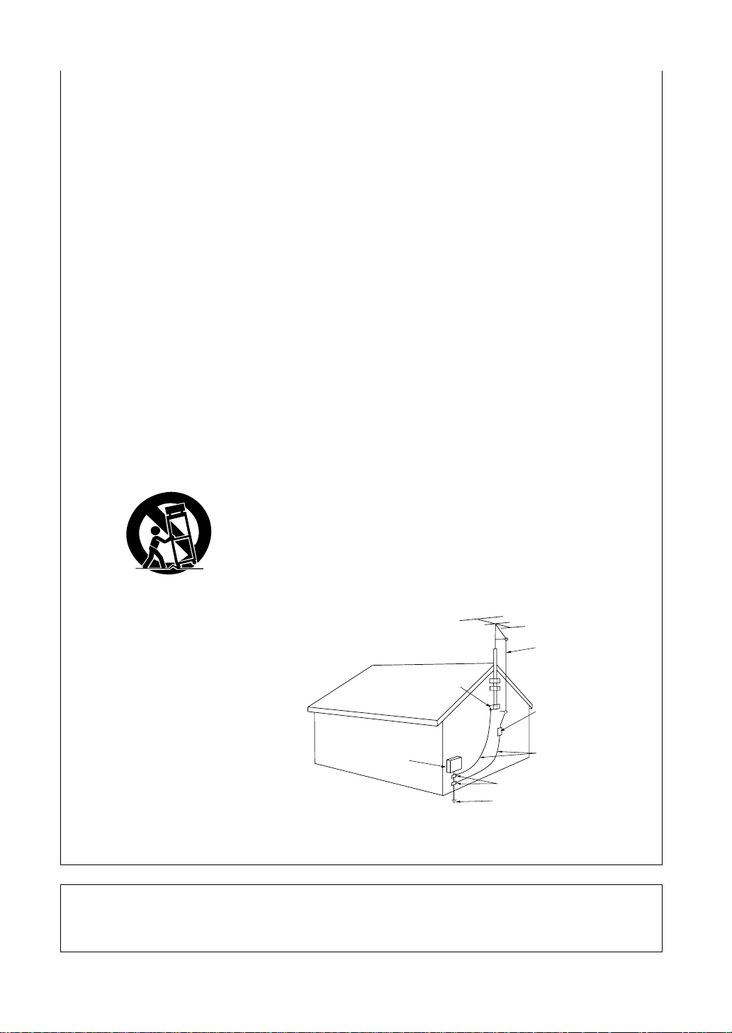
OUTDOOR ANTENNA GROUNDING — If an
outside antenna or cable system is connected
to the product, be sure the antenna or cable
system is grounded so as to provide some
protection against voltage surges and built-up
static charges. Article 810 of the National
Electrical Code, ANSI/NFPA 70, provides
information with regard to proper grounding of
the mast and supporting structure, grounding
of the lead-in wire to an antenna discharge
unit, size of grounding conductors, location of
antenna-discharge unit, connection to
grounding electrodes, and requirements for
the grounding electrode. See Figure A.
LIGHTNING — For added protection for this product
during a lightning storm, or when it is left
unattended and unused for long periods of
time, unplug it from the wall outlet and
disconnect the antenna or cable system. This
will prevent damage to the product due to
lightning and power-line surges.
POWER LINES — An outside antenna system
should not be located in the vicinity of overhead
power lines or other electric light or power
circuits, or where it can fall into such power
lines or circuits. When installing an outside
antenna system, extreme care should be taken
to keep from touching such power lines or
circuits as contact with them might be fatal.
OVERLOADING — Do not overload wall outlets,
extension cords, or integral convenience
receptacles as this can result in a risk of fire or
electric shock.
GROUND
CLAMP
ELECTRIC
SERVICE
EQUIPMENT
Fig. A
OBJECT AND LIQUID ENTRY — Never push
objects of any kind into this product through
openings as they may touch dangerous voltage
points or short-out parts that could result in a
fire or electric shock. Never spill liquid of any
kind on the product.
SERVICING — Do not attempt to service this
product yourself as opening or removing covers
may expose you to dangerous voltage or other
hazards. Refer all servicing to qualified service
personnel.
DAMAGE REQUIRING SERVICE — Unplug this
product from the wall outlet and refer servicing
to qualified service personnel under the
following conditions:
¶ When the power-supply cord or plug is
damaged.
¶ If liquid has been spilled, or objects have fallen
into the product.
¶ If the product has been exposed to rain or
water.
¶ If the product does not operate normally by
following the operating instructions. Adjust
only those controls that are covered by the
operating instructions as an improper
adjustment of other controls may result in
damage and will often require extensive work
by a qualified technician to restore the product
to its normal operation.
¶ If the product has been dropped or damaged in
any way.
¶ When the product exhibits a distinct change in
performance — this indicates a need for
service.
REPLACEMENT PARTS — When replacement
parts are required, be sure the service
technician has used replacement parts
specified by the manufacturer or have the
same characteristics as the original part.
Unauthorized substitutions may result in fire,
electric shock, or other hazards.
SAFETY CHECK — Upon completion of any service
or repairs to this product, ask the service
technician to perform safety checks to
determine that the product is in proper
operating condition.
WALL OR CEILING MOUNTING — The product
should not be mounted to a wall or ceiling.
HEAT — The product should be situated away
from heat sources such as radiators, heat
registers, stoves, or other products (including
amplifiers) that produce heat.
ANTENNA
LEAD IN
WIRE
ANTENNA
DISCHARGE UNIT
(NEC SECTION 810-20)
GROUNDING CONDUCTORS
(NEC SECTION 810-21)
GROUND CLAMPS
POWER SERVICE GROUNDING
ELECTRODE SYSTEM
(NEC ART 250, PART H)
NEC — NATIONAL ELECTRICAL CODE
Information to User
Alteration or modifications carried out without appropriate authorization may invalidate the user's right to
operate the equipment.
3
Features
Decoding of Dolby Digital, Dolby Pro Logic and DTS (Digital Theater Systems)
DTS is the latest and most widely used digital theater system for cinemas throughtout the world. The decoder
has been incorporated into this receiver and is able to achieve high sound quality as well as produce dynamic
surround sound effects. Also, there's no need to worry about program formats. When playing Dolby Digital,
Dolby Pro Logic or Dolby Surround software in the
automatically according to the input signal, all you have to do is enjoy!
“DTS” and “DTS Digital Surround” are trademarks of Digital Theater Systems, Inc.
Manufactured under licence from Digital Theater Systems, Inc.
Manufactured under license from Dolby Laboratories. “Dolby”, “AC-3”, “Pro Logic”, and double-D
symbol are trademarks of Dolby Laboratories. Confidential Unpublished Works. © 1992 - 1997 Dolby
Laboratories, Inc. All rights reserved.
Direct Energy MOS amplifier
This receiver incorporates 5 independent 100 watt power amplifiers, built with high-performance Hex power
MOS FET output transistors. This construction provides improved linearity and accurate reproduction of each
channel for true high fidelity reproduction from even the most demanding Dolby Digital and DTS program
sources.
Advanced Theater Modes
This mode enhances the sound of either film or music so a more dramatic effect can be achieved. The four
modes are each designed to accentuate specific sound qualities, giving the listener a wide range of possibilities.
DSP Surround Modes
(Dolby) Surround mode, decoding switches on
DSP (Digital Signal Processing) surround mode gives you the capability of transforming your living room into six
different sonic environments when listening to music.
Midnight Listening Mode
Midnight Listening mode allows you to obtain excellent surround sound effects even when listening at low
volumes, something that was previously impossible.
Digital Noise Reduction
Digital Noise reduction is the latest technology for filtering out unwanted noise. It produces clear, resonant
tones.
Illuminated Remote Control of Other Components
The supplied remote control can be used to operate a variety of other components simply by recalling the
appropriate preset codes or by using the learning function to teach the remote control new commands. In
addition, the multi-operation functions allow you to perform a variety of operations automatically.
The Energy-saving Design
This unit is designed to use minimal electricity when power is switched OFF (in Standby mode). Regarding the
value of the power consumption in standby mode, refer to “Specifications” on page 82.
4

Table of Contents
Before You Start
Checking the Supplied Accessories ................................................................ 6
How to Use This Manual.................................................................................. 6
Installing the Receiver...................................................................................... 6
Preparing the Remote Control......................................................................... 7
Opening the Front Panel ................................................................................. 7
Connecting Your Equipment
Audio Components .......................................................................................... 8
Video Components ........................................................................................... 9
Digital Connections .........................................................................................10
External Decoder Input .................................................................................. 12
Antennas ..........................................................................................................13
Speakers...........................................................................................................14
Connecting additional amplifiers ...................................................................17
Power connections (AC OUTLETS) ................................................................17
Displays & Controls
Display ..............................................................................................................18
Front Panel .......................................................................................................20
Remote Control............................................................................................... 22
Surround Sound Set Up
On Screen Display .......................................................................................... 24
Setting Up for Surround Sound .................................................................... 24
Basic Playback
Playing Sources with Stereo Sound ..............................................................35
Sound modes...................................................................................................36
Selecting a Sound Mode.................................................................................38
Playing Sources with Dolby Digital or DTS Sound...................................... 39
Switching ANALOG/DIGITAL Signal Input .................................................. 40
Reducing noise during playback (DIGITAL NR Function) .............................41
Listening in MIDNIGHT LISTENING Mode ................................................... 42
External decoder playback............................................................................. 43
96kHz 24Bit Performance ................................................................................43
Listening in LOUDNESS Mode .......................................................................44
Direct playback ............................................................................................... 44
Adjusting bass and treble (Tone Control) ......................................................44
Adjusting the brightness of the display........................................................ 45
.....................................................................................
.................................................................
.............................................................................
......................................................................
......................................................................................
18
24
35
6
PREPARATION
8
SET
UP
OPERATION
Using the Tuner
Automatic and Manual Tuning .......................................................................46
Direct Access Tuning ...................................................................................... 47
Memorizing Frequently Used Stations ..........................................................48
Recalling Memorized Stations........................................................................49
Remote Control of Other component
Setting Up the Remote Control to Control Other Components...................50
Remote Controlling Other Components ........................................................54
Using Other Functions
Recording from Audio Components ..............................................................62
Recording from Digital Audio Components ..................................................63
Recording from Video Components ..............................................................64
Multi Operations ..............................................................................................65
System OFF ......................................................................................................67
Setting up the direct function .........................................................................68
Resetting the Remote Control ........................................................................70
Multi-Room ......................................................................................................72
Techno Tidbits & Problem-solving
Dolby Digital ................................................................................................... 77
DTS ...................................................................................................................78
Preset Code List .............................................................................................. 79
Troubleshooting .............................................................................................. 80
Specifications...................................................................................................82
....................................................................................
................................................
.........................................................................
......................................................
46
50
62
77
5
Before You Start
Checking the Supplied Accessories
Please check that you have received all of the following supplied accessories.
FM wire antenna
AM loop antenna “AA” IEC LR6 batteries × 2 Remote control unit
How to Use This Manual
This manual is for the VSX-D908S Audio/Video Multi-Channel Receiver.
This manual is divided into three main sections which will tell you how to setup and use the unit :
PREPARATION
First carry out the tasks below in this “Before You Start” section to prepare the remote control, then connect
the receiver to your other components as described in “Connecting Your Equipment” (p.8). Take special care to
connect your digital equipment like DVDs and LDs properly to be able to take advantage of the receiver’s
surround sound systems(p.10-11).To learn about a specific button, control, or indicator, see “Displays &
Controls” starting on p.18.
SET UP
Performing the tasks in “Surround Sound Set Up” (p.24) is essential to get proper surround sound.
OPERATION
To play some music or soundtrack refer to “Basic Playback” on p.35. “Using the Tuner” (p.46) explains how to
use the radio of this unit. Doing the operations in “Remote Control of Other Components” (p.50) is highly
recommended so you can use this unit’s remote control for all your components. “Using Other Functions”
(p.62) explain the other possibilities of the receiver.
“Techno Tidbits & Problem-solving” (p.77) provide detailed technical information and a troubleshooting guide.
The following marks and symbols are used throughout the manual:
Provides additional information, precautions, and advice.
Indicates a blinking button, indicator, or display.
Indicates a steadily lit button, indicator, or display.
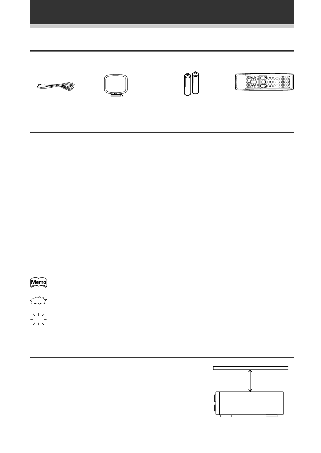
Installing the Receiver
Please note:
• Do not place objects directly on top of this unit.
This would prevent proper heat dispersal.
• When installing in a rack, shelf, etc., be sure to
leave more than 8 inches of space above the
receiver.
6
8 inches (20 cm.)
Receiver
Before You Start
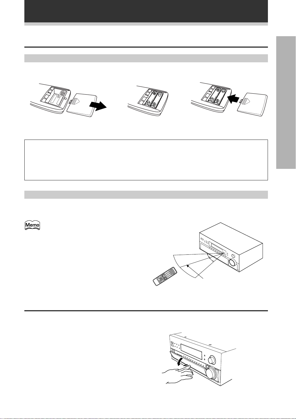
Preparing the Remote Control
Loading the batteries
Load the batteries into the remote control as shown below.Please use alkaline batteries.
12
When you notice a decrease in the operating range of the remote control, replace all batteries with new ones.
CAUTION!
Incorrect use of batteries may result in such hazards as leakage and bursting. Observe the following
precautions.
• Never use new and old batteries together.
• Insert the plus and minus sides of the batteries properly according to the marks in the battery case.
• Batteries with the same shape may have different voltages. Do not use different batteries together.
3
PREPARATION
Operating range of remote control unit
The area in which you can use the remote control to operate the VSX-D908S is fairly large. To use, point the
remote control toward the remote sensor on the front panel of this unit while within the range shown below.
Remote control may not function properly if:
• There are obstacles between the remote
control and the remote sensor.
• Direct sunlight or fluorescent light is
shining onto the remote sensor.
• The receiver located near a device
emitting infrared rays.
• Operated simultaneously with another
remote control which uses infrared rays.
30°
30°
23 feet (7 m)
Opening the Front Panel
To open the front panel push gently on the lower third of the panel with your finger.
7
Connecting Your Equipment
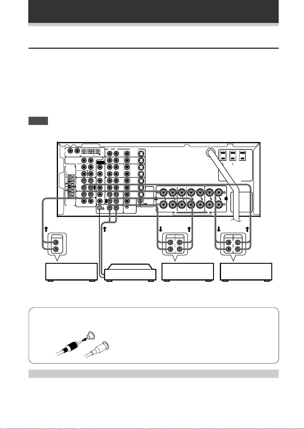
Audio Components
To begin set up connect your audio components to the jacks as shown below. These are all analog connections
and your analog audio components (turntable, cassette deck) use these jacks. Remember that for components
you want to record with you need to hook up four plugs (a set of stereo ins and a set of stereo outs), but for
components that only play (like a turntable) you only need to hook up one set of stereo plugs (two plugs). To use
DTS surround sound features you must hook up your digital components to the digital inputs but it is also a good
idea to hook up your digital components to analog audio jacks. If you want to record to/from digital components
(like an MD) to/from analog components you must hook up your digital equipment with these analog
connections. See p.10,11 for more on digital connections.
When connecting your equipment always make sure the power is turned off and the power cord is
disconnected from the wall outlet.
NOTE
• The arrows indicate the direction of the audio signal.
OUTPUT
DIGI AL
1234
PREOU
FM
AN ENNA
FM UNBAL
75Ω
AM LOOP
AN ENNA
PCM/ /D S IN
S
R
F
R
C
APE2
MONI OR
CD
MUL I
ROOM
&
SOURCE
RL
PCM/ /D S
OU
S
XT A
L
FLF
S
W
P
L
A
Y
R
E
C
I
N
O
U
L
F
R
S
L
S
R
P
L
C
A
Y
R
S
E
W
C
RL
HONO
VIDEO
DVD
S2
LD
N
IN
V/
S2
SA
N
IN
S2
IN
N
VCR1
S2
OU
OU
S2
IN
N
OU
MD/
IN
REMO E
MUL I ROOM
&SOURCE
VIDEO
VIDEO
S2
OU
OU
OU
OU
N
FR FL C SR SL R L
O
MONI OR
V
S2
OU
AB
IN
CON ROL
FRON
SPEAKERS
REC PLAY
L
R
CD player
Turntable
MD recorder
or Cassette deck
If your turntable has a
ground wire, connect it
to the SIGNAL GND
terminal.
7 Audio cords
Use audio cords (not supplied) to connect the audio components.
R
L
Connect red plugs to R (right) and white plugs to L (left).
Be sure to insert completely.
CEN ER
URROUND
PEAKERS
SPEAKERS
T T MA A T A M M
L
R
SWI CHED
100W(0 8A)MAX
AC 120V 60Hz
CAUTION:
A N:
U LE S
CA
AT N:
FRO
SPEAK RS
REC PLAY
L
R
Cassette deck
(with REC monitor)
UNSWI CHED
100W 0 8A)MAX
Cassette deck placement
Depending on where the cassette deck is placed, noise may occur during playback of your cassette deck which
is caused by leakage flux from the transformer in the receiver. If you experience noise, move the cassette deck
farther away from the receiver.
8
Connecting Your Equipment
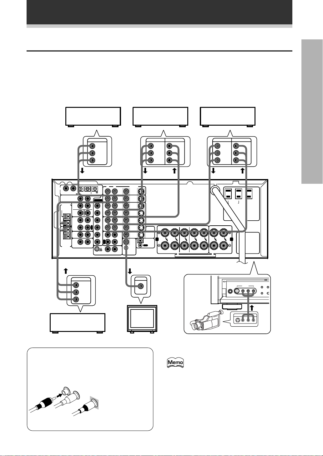
Video Components
Connect your video components to the jacks as shown below. Regarding digital video components (like a DVD),
you must use the analog connections pictured on this page for the video signal but in order to use Dolby Digital
you should hook up their audio to a digital input (see the next page). It is also a good idea to hook up your digital
components with analog audio connections as well (see the previous page). To cover all possible laser discs a
DVD/LD player or LD player requires an analog connection (as shown here) and two digital connections (see the
next page).
When connecting your equipment always make sure the power is turned off and the power cord is
disconnected from the wall outlet.
DVD player
(or LD player)
Video deck (1)
Video deck (2)
PREPARATION
OUTPUT
DIGI AL
1234
PCM/ S IN
PREOU
FM
AN ENNA
FM UNBAL
75Ω
MONI OR
MUL I
ROOM
AM LOOP
SOURCE
AN ENNA
S
R
F
R
C
APE2
CD
&
RL
PCM/ /D S
OU
S
XT A
L
FLF
S
W
P
L
A
Y
R
E
C
I
N
O
U
OUTPUT
VIDEO
L
R
TV tuner
(or Satellite tuner)
VIDEO
L
R
L
F
R
S
L
S
R
C
S
W
RL
P
L
A
Y
R
E
C
APE1
PHONO
DVD
LD
IN
SA
IN
IN
OU
IN
OU
MD/
IN
V/
M I ROOM
VIDEO
S2
N
S2
N
S2
N
S2
OU
S2
N
S2
OU
VIDEO
OU
VIDEO
OU
REMO E
N
SOURCE
INPUT
VIDEO
TV
(monitor)
OUTPUT INPUT
VIDEO
L
L
R
R
FR FL C SR SL R L
AB
FRON
SPEAKERS
SURROUND
CEN ER
SPEAKERS
SPEAKERS
T T MA A T A M M
OU
MONI OR
S2
OU
IN
CON ROL
O
V
VIDEO
7 Front
OUTPUT INPUT
VIDEO
L
R
SWI CHED
100W(0 8A)MAX
AC 120V 0Hz
A N:
FRON
SPEAKERS
- A A W T T
V
VIDEO
L
R
CAUT N:
U LE
CA
AT N:
V T
V
NSWI CHED
1 W 0 8A)MAX
A
V
XT A
T
AK
Video
camera
(etc.)
VIDE
V
7 Audio/Video cords
Use audio/video cords (not supplied) to connect
the video components and a video cord to
connect the monitor TV.
R
L
Connect red
plugs to R (right),
white plugs to L
VIDEO
(left), and the
yellow plugs to
VIDEO.
Be sure to insert
completely.
Front video connections are accessed via the front
panel input selector as “VIDEO.”
If your video components have S-video
jacks, you could use S-video cords (not
supplied) to connect them on the back of
the receiver. These jacks are labeled by the
Japanese designation “S2” on the VSXD908S but they are simply S-video jacks.
However, if you use S-video cords for your
video hook ups you must also hook up your
TV with S-video connections. Conversely, if
you use regular composite video cords for
video hook ups, you should use them for
your TV as well.
9
Connecting Your Equipment
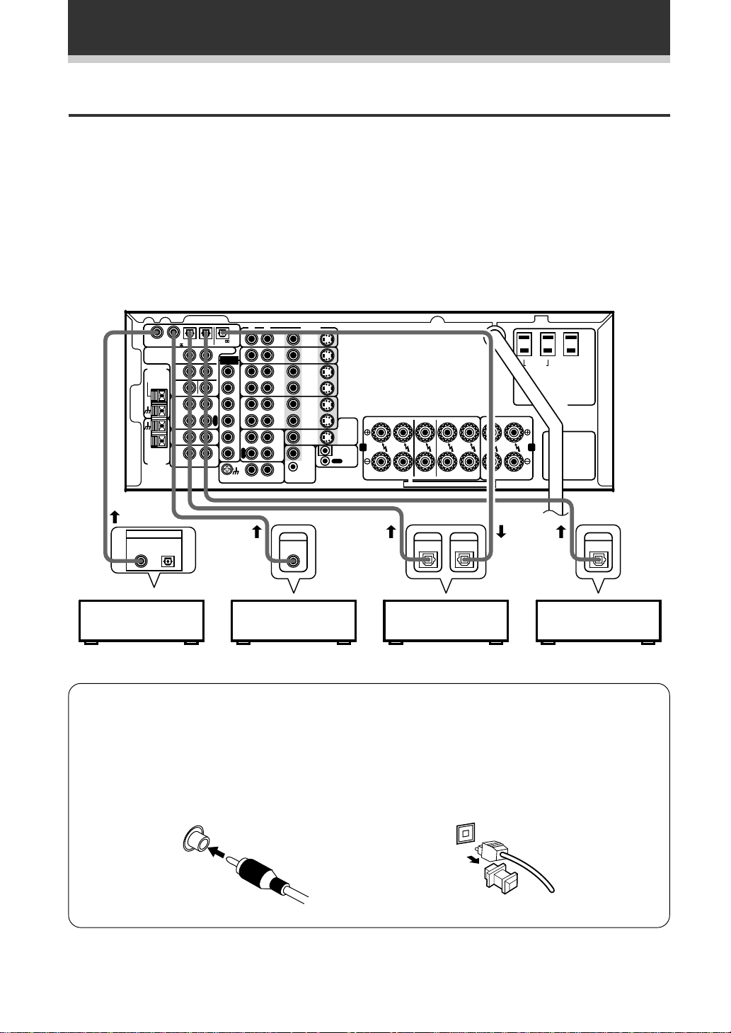
Digital Connections
In order to use Dolby Digital/DTS soundtracks you need to make digital audio connections. You can do this by
either coaxial or optical connections (you don’t need to do both). The quality of these two types of connections
is the same but since some digital components only have one type of digital terminal, it is a matter of matching
like with like (for example, the coaxial out from the component to coaxial in on the receiver). The VSX-D908S has
two coaxial and two optical inputs for a total of four digital inputs. Connect your digital components as shown
below. There is one digital out jack which is marked PCM/2/DTS OUT. If you connect this to the optical input
on a digital recorder (currently these include MD, DAT and CD-R) you can make direct digital recordings with this
unit.
When connecting your equipment always make sure the power is turned off and the power cord is
disconnected from the wall outlet.
1
PREOU
FM
AN ENNA
FM UNBAL
75Ω
AM LOOP
AN ENNA
DIGITAL OUT
OPT
P M/ /D S IN
S
R
F
R
C
PE2
NI OR
CD
UL I
OM
&
URCE
.
PCM/ /D S
OU
S
XT A
L
FLF
S
W
P
L
A
Y
R
E
C
I
N
O
U
L
F
R
S
L
S
R
P
L
C
A
Y
R
S
E
W
C
RL
DVD player CD player MD recorder
PHONO
DVD
/LD
IN
V/
SA
IN
IN
VCR1
OU
IN
VCR2
OU
MD/
APE1
IN
REMO E
MUL I ROOM
&SOURCE
DIGITAL
OUT
VIDEO
VIDEO
OU
VIDEO
OU
IN
S2
IN
S2
IN
S2
IN
S2
OU
S2
IN
S2
OU
IN
OU
FR FL C SR SL L
O
MONI OR
V
S2
OU
AB
CON ROL
FRON
CEN ER
SPEAKERS
SURROUND
SPEAKERS
SPEAKERS
T T A A T A M
DIGITALINDIGITAL
OUT
FRON
PEAKERS
SWI CHED
100W(0 8A)MAX
AC 120V 60Hz
A N:
C
A ON:
CAUTION:
U LE S
UNSWI CHED
100W(0 8A)MAX
DIGITAL
OUT
TV tuner
(or Satellite tuner)
7 Digital audio cords/Optical cables
Commercially available digital audio coaxial cords (standard video cords can also be used) or optical cables
(not supplied) are used to connect digital components to this receiver.
When you use optical digital input or output terminals, pull off the caps and insert the plugs. Be sure to
insert completely.
10
Digital audio cord
(or standard video cord)
Optical cable

Connecting Your Equipment
Example of Connection Using a DVD/LD or LD player
When playing LD recorded in Dolby Digital
To connect a DVD/LD player or LD player with it’s AC-3 RF output, a commercially available RF demodulator
(RFD-1) is required. The RF demodulator changes the RF signal to a digital signal which is then processed by the
VSX-D908S model through their digital input jacks. For more details, refer to the instruction manual supplied
with the RFD-1.
PREPARATION
DIGI AL
1234
PREOU
FM
AN ENNA
FM UNBAL
75Ω
AM LOOP
AN ENNA
PCM/
(OP )
PCM/ /D S IN
S
R
F
R
C
APE2
MONI OR
CD
MUL I
ROOM
&
SOURCE
DIGI AL OU
RL
PCM/ D S
OU
S
XT A
L
FLF
L
F
S
R
W
P
S
L
A
L
Y
R
S
E
R
C
P
I
L
C
A
N
Y
R
O
S
E
U
W
PCM/
(OP )
C
DIGI AL IN
PHONO
PCM/
RL
PCM/
RF demodulator RFD-1
DVD
/LD
IN
SA
IN
IN
VCR1
OU
IN
VCR2
OU
MD/
APE1
IN
V/
MUL I ROOM
RF IN
(AC 3)(LD)
&SOURCE
VIDEO
OU
OU
V DEO
OU
V DEO
OU
REMO E
IN
OPTICAL
S2
IN
S2
IN
S2
IN
S2
S2
IN
S2
DIGITAL IN
SWI CHED
100W(0 8A)MAX
A N:
FR FL C SR SL R L
O
MONI OR
V
S2
OU
AB
IN
CON ROL
OU
FRON
CEN ER
SPEAKERS
SPEAKERS
T T A A T A M M
SURROUND
SPEAKERS
RF OU
(AC 3)(LD)
DIGI AL OU
PCM (OP )
1
23
FRON
SPEAKERS
UNSWI CHED
100W(0 8A)MAX
AC 120V 60Hz
CAUTION:
U LE S
CA
AT ON:
VIDEO
OUTPUT
L
R
DVD/LD player
COAXIAL
or LD player
Make sure the RF demodulator digital in
switch is set correctly (optical or coaxial
depending on the connection).
11
Connecting Your Equipment
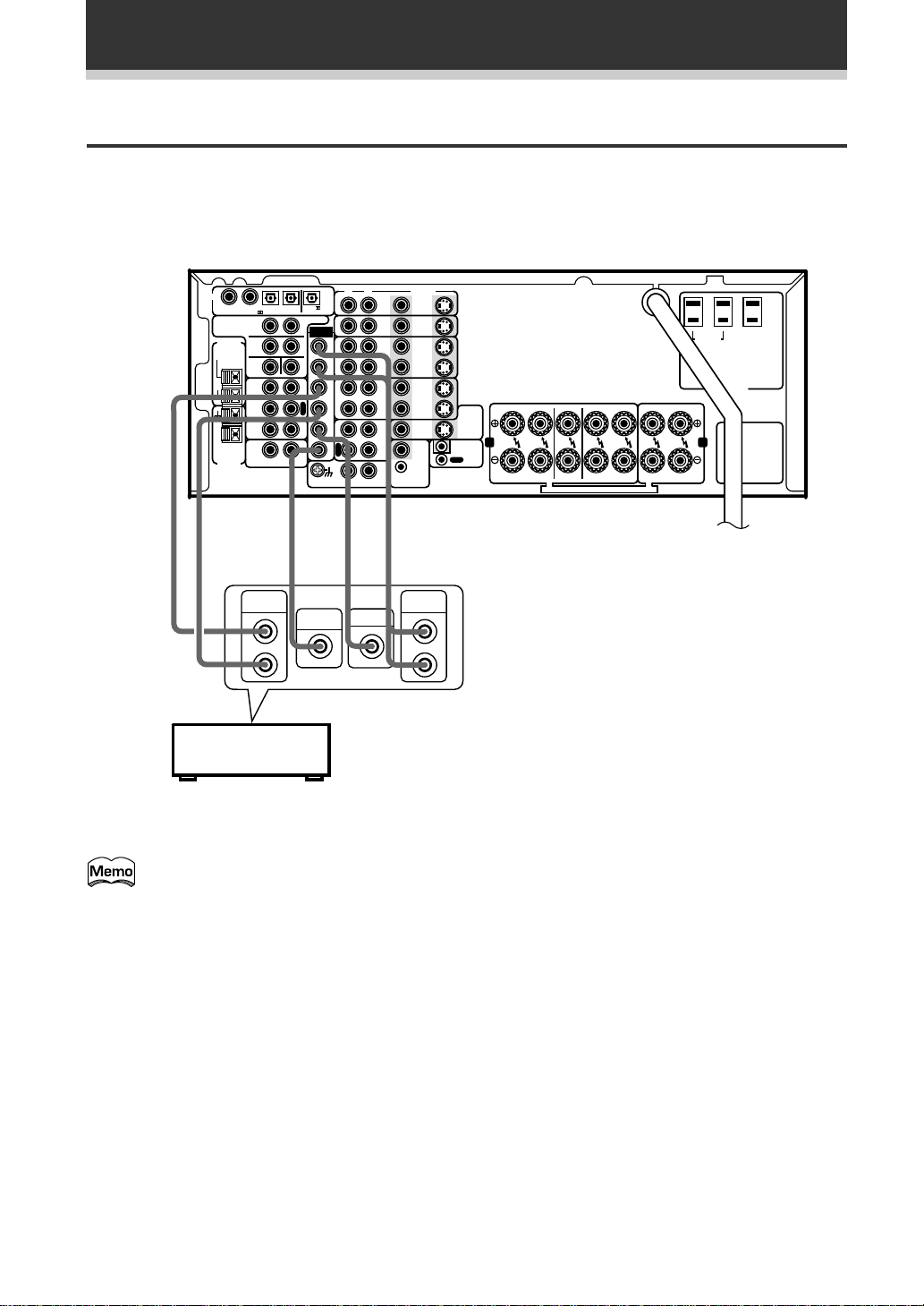
External Decoder Input
In some cases you may need an external decoder to play special analog or DVD sources. If you find you need an
external decoder hook one up as shown below, but for most people this component is unnecessary. (See p.43)
When connecting your equipment always make sure the power is turned off and the power cord is
disconnected from the wall outlet.
DIGI AL
1234
PCM/ /D S IN
PREOU
FM
AN ENNA
FM UNBAL
75Ω
AM LOOP
AN ENNA
»
SURROUND
S
R
F
R
C
APE2
MONI OR
CD
MUL I
ROOM
&
SOURCE
OUTPUT
RL
L
PCM/ D S
OU
S
XT A
L
FLF
S
W
P
L
A
Y
R
E
C
I
N
O
»
SUB
WOOFER
L
F
R
S
L
S
R
P
L
C
A
Y
R
S
E
W
C
RL
CENTER
R
Components equipped with 5.1
channel analog output jacks
»
PHONO
VIDEO
DVD
S2
/LD
IN
IN
V/
S2
SA
IN
IN
S2
IN
IN
S2
OU
OU
S2
IN
IN
VCR
S2
OU
OU
V DEO
OU
MD
APE
V DEO
OU
OU
REMO E
IN
IN
MUL I ROOM
&SOURCE
FR FL C SR SL R L
O
MONI OR
V
S2
OU
AB
IN
CON ROL
FRON
SPEAKERS
SURROUND
CEN ER
SPEAKERS
SPEAKERS
T T A A T A M M
FRON
SPEAKERS
SWI CHED
100W(0 8A)MAX
AC 120V 60Hz
A N:
CA
AT ON:
100W(0 8A)MAX
CAUTION:
U LE S
UNSWI CHED
»
FRONT
OUTPUT
L
R
12
You can’t use the tuner and phono functions
with an external decoder input.
Connecting Your Equipment
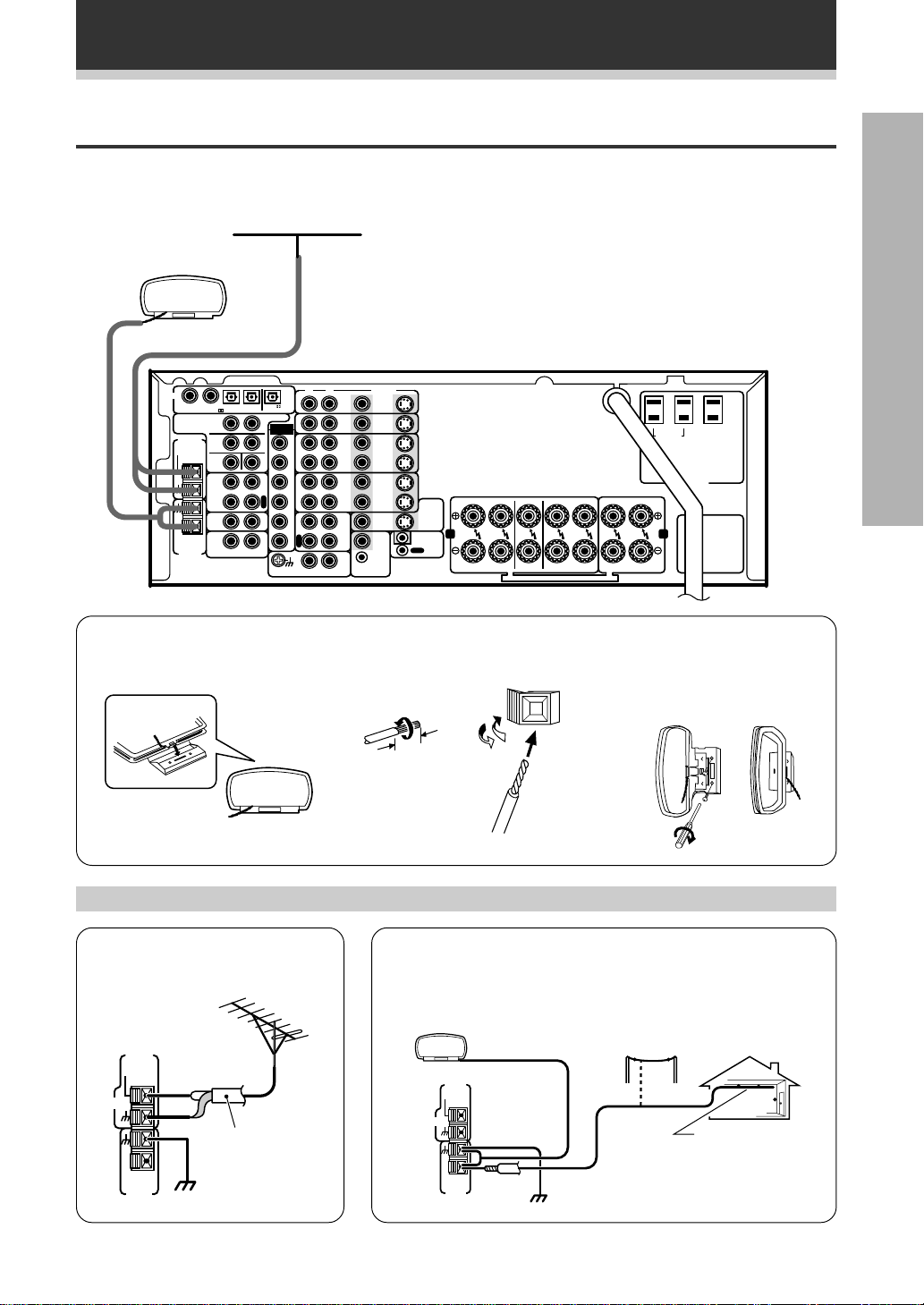
Antennas
Hook up the supplied radio antennas as shown below. When connecting your equipment always make sure the
power is turned off and the power cord is disconnected from the wall outlet.
FM wire antenna
AM loop antenna
(See below)
Connect the FM wire antenna and fully extend to the “T” shape.
(For best reception, attach horizontally analog a window frame, etc.)
PREPARATION
DIGI AL
1234
PREOU
FM
AN ENNA
FM UNBAL
75Ω
AM LOOP
AN ENNA
PCM/ /D S IN
S
R
F
R
C
APE2
MONI OR
CD
MUL I
ROOM
&
SOURCE
RL
PCM/ D S
OU
S
XT A
L
FLF
S
W
P
L
A
Y
R
E
C
I
N
O
U
L
F
R
S
L
S
R
C
S
W
RL
P
L
A
Y
R
E
C
PHONO
VIDEO
DVD
S2
/LD
IN
IN
V/
S2
SA
IN
IN
S2
IN
IN
VCR1
S2
OU
OU
S2
IN
IN
VCR2
S2
OU
OU
V DEO
OU
MD/
APE1
N
MUL I ROOM
&SOURCE
V DEO
REMO E
IN
OU
OU
IN
FR FL C SR SL R L
O
MONI OR
V
S2
OU
AB
CON ROL
FRON
SPEAKERS
7 AM loop antenna
1 Assemble the antenna. 2 Twist exposed wire strands
together and insert.
3/8 in. (10 mm)
Using external antennas
SURROUND
CEN ER
SPEAKERS
SPEAKERS
T T A A T A M M
SWI CHED
100W(0 8A)MAX
AC 120V 60Hz
CAUTION:
U LE S
CA
AT ON:
UNSWI CHED
FRON
SPEAKERS
100W(0 8A)MAX
A N:
3 Attach to a wall, etc. (if
desired) and face toward the
direction providing the best
reception.
7 To improve FM reception
Connect an external FM antenna.
FM
AN ENNA
FM UNBAL
75Ω
FM
AN ENNA
75 Ω coaxial
cable
AM LOOP
AN ENNA
ground
7 To improve AM reception
Connect a 15 to 18 feet (5~6 meter) length of vinyl-coated wire
to the AM antenna terminal in addition to the supplied AM loop
antenna.
For the best possible reception, suspend horizontally outdoors.
Outdoor antenna
FM
AN ENNA
M A
7 Ω
A T A
M
AM
A T A
ground
15~18 feet
(5~6 m)
Indoor antenna
(Vinyl-coated
wire)
13
Connecting Your Equipment
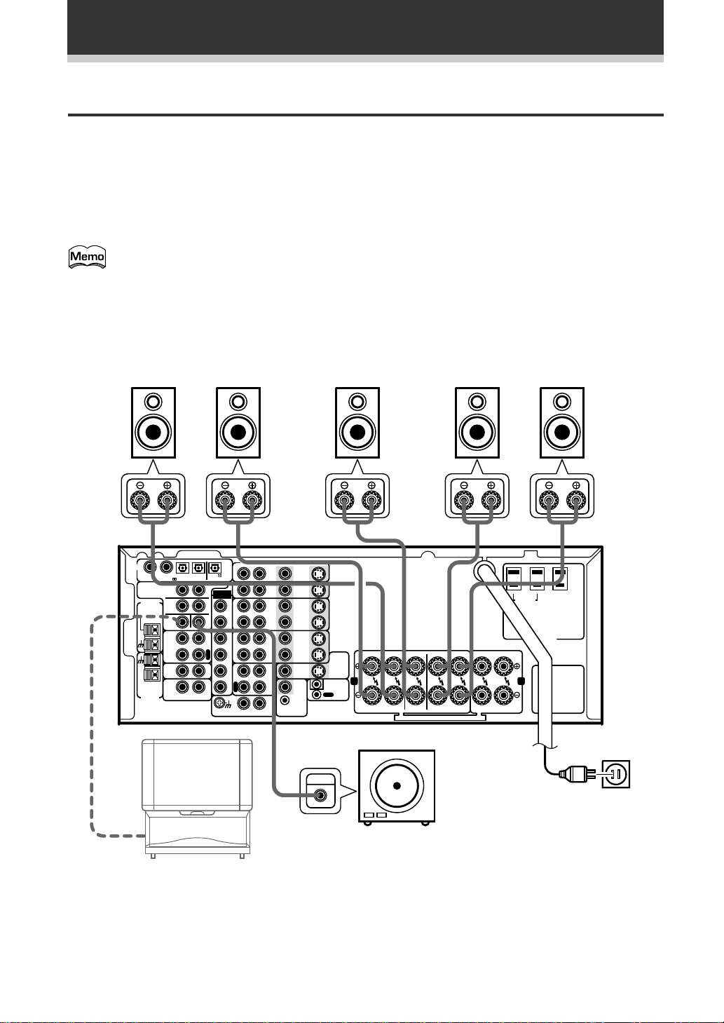
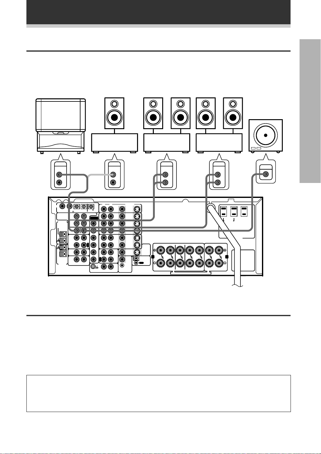
Speakers
A full complement of six speakers is shown here but, naturally, everyone’s home set up will vary. Simply
connect the speakers you have in the manner described below. The VSX-D908S will work with just two stereo
speakers (called “front” speakers in the diagram) but the receiver is designed to be used with at least three
speakers.
Make sure you connect the speaker on the right to the right terminal and the speaker on the left to the left
terminal. Also make sure the positive and negative (+/–) terminals on the receiver match those on the speakers.
When connecting your equipment always make sure the power is turned off and the power cord is
disconnected from the wall outlet.
The VSX-D908S has two speaker systems, A & B. A is the main system supporting the full complement
of surround sound speakers. If you switch on both A & B speaker systems, only front speakers and the
sub-woofer will be audible. No sound will come from the center or surround speakers but multi channel
sources will be down-mixed to the active speakers so no sound will be lost. Similarly, if you choose just
the B system you‘ll only hear the front speakers connected to the B system and multi channel sources
will be down-mixed to these two speakers.
Front Speakers (A) Center Speaker
L
DIGI AL
1234
PCM/ /D S IN
PREOU
FM
AN ENNA
FM UNBAL
75Ω
AM LOOP
AN ENNA
APE2
MONI OR
CD
MUL I
ROOM
&
SOURCE
S
R
F
R
C
RL
PCM/ D S
OU
S
L
FLF
S
W
P
L
A
Y
R
E
C
I
N
O
U
XT A
R
DVD
S2
/LD
IN
IN
V/
S2
SA
IN
IN
S2
L
F
R
S
W
IN
IN
VCR1
S2
OU
OU
S2
IN
L
S
R
P
L
C
A
Y
R
S
E
C
PHONO
IN
VCR
S2
OU
OU
V DEO
OU
MD
APE
N
MUL I ROOM
&SOURCE
V DEO
REMO E
IN
OU
OU
IN
FR FL C SR SL R L
O
MONI OR
V
S2
OU
AB
CON ROL
Powered sub woofer
TV
(To be used as
the center
INPUT
speaker)
FRON
CEN ER
SPEAKERS
SPEAKERS
T T A A T A M M
Rear Speakers
SURROUND
SPEAKERS
SR
FRON
SPEAKERS
SWI CHED
L 100W(0 8A)MAX
A N:
UNSWI CHED
100W(0 8A)MAX
AC 120V 60Hz
CAUT ON:
U LE S
CA
AT ON:
SLRC
Be sure to complete all other
connections before connecting
this unit to the AC power source.
14
When using the speaker on your TV as the center
speaker, connect the CENTER PREOUT jack on this
unit to the audio input jack on your TV. In this case,
the center speaker shown is unnecessary.
Connecting Your Equipment
dB
SIGNAL
SELECT
ANALOG
SP
A
VOLUME
P
N
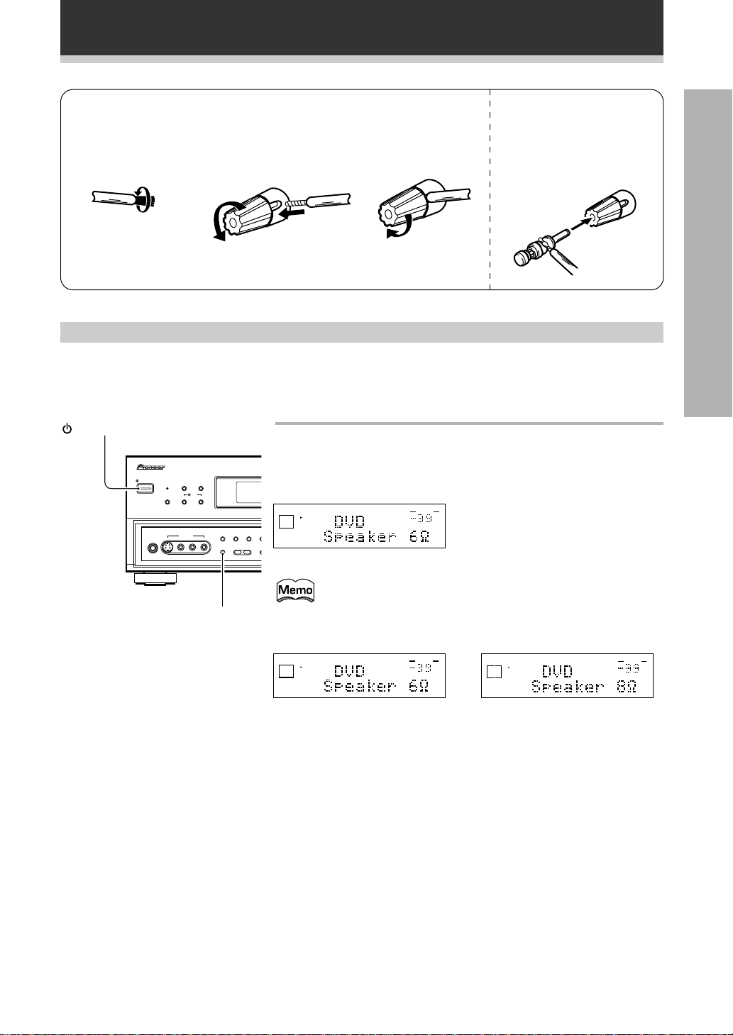
7 Speaker terminals
1 Twist exposed wire
strands together.
3/8 in.(10 mm)
2 Loosen speaker
terminal and insert
exposed wire.
3 Tighten terminal. The speaker terminals also
accept single banana
plugs.
(Refer to speaker manual
for details.)
Speaker impedance
You can change the speaker impedance to suit the kind of speakers you have in your home system but we
recommend using speakers with an impedance of 8 Ω -16 Ω (the default setting). If you are using 6 Ω less than
8 Ω impedance speakers, you need to change the impedance setting.
PREPARATION
STANDBY/ON
STANDBY/ON
AUDIO/VIDEO MULT-CHANNEL RECEIVER
STANDBY
SGNAL SELECT ADVANCED STANDARD
5CHANNEL EQUAL POWER OUTPUT
SV DEO
PHONES
DSP
STEREO
MODE
DTS
EXTERNAL
DECODER IN DIRECT LOUDNESS MID
VDEO INPUT
VDEO
L AUDIO R
SPEAKERS BASS +
SPEAKERS
N∫m /?˘∫
First turn the receiver off, then press the power button
while holding down the SPEAKERS button.
Digital Signa
Choose the impedance setting by pressing the SPEAKERS button again.
You can choose the 8 Ω-16 Ω setting or the 6 Ω-8 Ω setting.
SGNAL
SELECT
A
ANALOG
SP
To check which impedance the amp is set to hold down the
SPEAKERS button for 2-3 seconds. You’ll get a display like the
one shown below right telling you the speaker impedance
setting.
SGNAL
SELECT
A
ANALOG
SP
(This display indicates a 6 Ω less
than 8 Ω impedance setting)
VOLUME
(This display indicates an 6 Ω less than
dB
8 Ω impedance setting)
VOLUME
dB
or
(This display indicates an 8 Ω-16 Ω
impedance setting)
15
Connecting Your Equipment
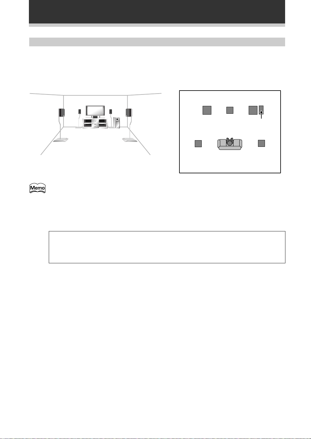
Speaker placement
If you have a multiple speaker arrangement the placement of the speakers is extremely important. To achieve
the best possible surround sound, install your speakers as shown below. Make sure all speakers are installed
securely to prevent accidents and improve sound quality. Be sure to consult your speaker manuals for the best
placement of the speakers. Some speakers are designed to be floor-standing but others benefit greatly from
speakers stands which raise them off the floor.
Front
Left
Surround
Left
• Install the left and right front speakers at equal distances from the TV.
• When installing speakers near the TV, we recommend using magnetically shielded speakers to
prevent possible interference such as distortion in the color of the TV screen. If you do not have
magnetically shielded speakers and notice discoloration of the TV screen, place the speakers farther
away from the TV.
• Install the center speaker above or below the TV so that the sound of the center channel is localized
at the TV screen.
Center
Listening
Position
Front
Right
Sub
Woofer
Surround
Right
CAUTION:
When installing the center speaker on top of the TV, be sure to secure it with tape or some other
suitable means. Otherwise, the speaker may fall from the TV due to external shocks such as
earthquakes, and it may lead to endangering those nearby or damaging the speaker.
• If possible, install the surround speakers slightly above ear level.
• It may be difficult to obtain a cohesive surround effect if the surround speakers are installed farther
away from the listening position than the front and center speakers.
16
Connecting Your Equipment
Connecting additional amplifiers
Although the VSX-D908S has more than sufficient power for any home use, it is possible to add additional
amplifiers to your system. If you want to use separate amplifiers to power your speakers, make the
connections shown below.
When connecting your equipment always make sure the power is turned off and the power cord is
disconnected from the wall outlet for all the eqiuipment.
PREPARATION
L-Audio
(MONO)
PIONEER
projection TV
(for center
channel)
AUDIO
IN
L
R
D GI AL
1234
CM/ D S N
S
PREOU
R
FM
AN ENNA
F
R
FM UNBAL
75Ω
APE2
MONI OR
CD
MUL I
ROOM
&
AM LOOP
SOURCE
AN ENNA
(or)
RL
PCM/ /D S
OU
S
XT A
L
FLF
W
P
L
A
Y
R
E
C
I
N
O
U
Amplifier
(for center
channel)
AUDIO
IN
RL
L
F
R
S
L
S
R
P
L
C
A
Y
R
S
E
W
C
PHONO
VCR2
APE1
DVD
/LD
IN
SA
IN
IN
IN
OU
MD/
N
L
R
V/
REMO E
MUL I ROOM
&SOURCE
VIDEO
V DEO
OU
V DEO
OU
IN
Amplified
sub woofer
Amplifier
(for surround
channels)
AUDIO
IN
L
R
S2
IN
S2
IN
S2
IN
S2
OU
S2
IN
S2
OU
OU
FR FL C SR SL R L
O
MONI OR
V
S2
OU
AB
IN
CON ROL
FRON
CEN ER
SPEAKERS
SPEAKERS
T T A A T A M M
SURROUND
SPEAKERS
Amplifier
(for front
channels)
AUDIO
IN
L
R
SWI CHED
100W(0 8A MAX
A N
FRON
SPEAKERS
UNSWI CHED
100W(0 8A)MA
AC 120V 60Hz
CAUT ON
U LE S
CA
AT ON:
INPUT
Power connections (AC OUTLETS)
[SWITCHED TOTAL 100 W (0.8 A) MAX]
Power supplied through these outlets is turned on and off by the receiver’s POWER switch. Total electrical
power consumption of connected equipment should not exceed 100 W (0.8 A).
[UNSWITCHED 100 W (0.8 A) MAX]
Power flows continually to this outlet, regardless of whether the receiver is switched ON or OFF. Electrical
power consumption of the connected equipment should not exceed 100 W (0.8 A).
CAUTION!
• To avoid overheating, fire risk, and possible malfunction do not connect high-wattage appliances such as
heaters, irons, monitors, or TV sets to the AC OUTLETS.
• Remove the power plug from the wall socket to disconnect this unit from the AC power source when not
in regular use, for example, when on vacation.
17
Displays & Controls
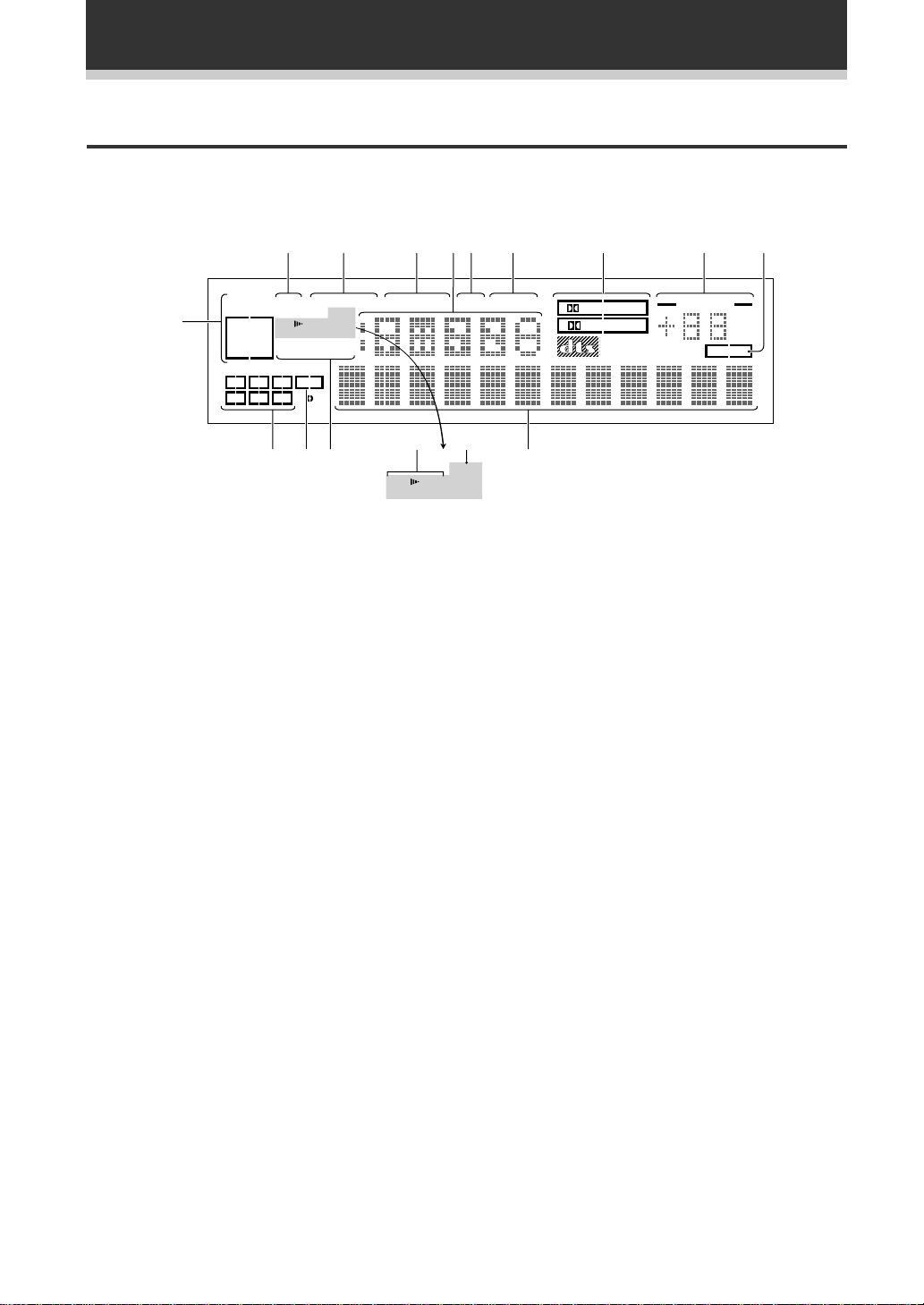
Display
All the display information is explained and/or referenced here.
23 4567 9
1
ANALOG
DIGITAL
AC-3DTS
C
L
LSSRS
-
OVER
SP AB
MONO STEREO
H.P
TUNED AMFM
LFE
R
=~ !
SELECT
1 SIGNAL SELECT indicators
Light to indicate the type of input signal assigned
for the current component (see “Front Panel”, %,
SIGNAL SELECT).
ANALOG : Lights when an analog signal is
selected.
DIGITAL : Lights when a digital audio signal is
selected (DVD/LD, CD, MD/TAPE1, TV/SAT,
VCR1, VCR 2).
AC-3 : Lights when a source with Dolby Digital
signals is played.
DTS : Lights when a source with DTS audio
signals is played.
2 Analog level indicators
OVER : If “ANALOG” is selected in SIGNAL
SELECT, this indicator lights to show that an
excessively strong signal is being processed.
When this occurs, press INPUT ATT on the front
panel to attenuate (lower) the signal. Also, when
“DIGITAL” is selected in SIGNAL SELECT, this
indicator lights to show that a source containing
an excessive amount of information is being
processed. If this occurs, see p. 38.
ATT : Lights when INPUT ATT is used to reduce
the level of the input signal (available in ANALOG
mode only).
3 LOUDNESS indicator (See p.44)
Lights when the LOUDNESS mode is on.
4 MIDNIGHT indicator (See p.42)
Lights when the MIDNIGHT LISTENING mode is
on.
5 Radio Frequency/Function indicator
Displays the function or the frequency of the
current radio station.
MIDNIGHTLOUDNESSATTSIGNAL
SP AB
DSP
STEREO
@#
H.P
6 DSP indicator (See p.37, 38)
7 STEREO indicator (See p.37, 38)
8 2 Surround/dts mode indcators
9 MASTER VOLUME indication
0 TAPE 2 indicator
- Program Format indicator
80
PRO LOGIC
DIGITAL
Light when a DSP or Advanced Theater mode is
selected.
Lights when a STEREO mode is selected.
2 DIGITAL : When the 2 Surround/dts mode
on the receiver is on, this indicator lights to
indicate playback of a Dolby Digital signal.
However, 2 PRO LOGIC lights during 2 channel
playback of Dolby Digital.
2 PRO LOGIC : When the 2 Surround/dts
mode on the receiver is on, this indicator lights
during 2 channel playback. ( Both B or A+B
speaker systems turn off automatically when
headphones are plugged in.)
DTS : Lights when DTS signals are input.
Displays current level of master volume.
Lights when the TAPE 2 monitor is on.
When a Dolby Digital or DTS signal is input, he
following indicators light to show the channels
being played back.
L : Left front*
1*2
, C : Center*1, R : Right front*1*2,
LS : Left surround*
RS : Right surround*
*1: Indicates 5.1ch Dolby Digital or DTS playback.
*2: Indicates Dolby Pro Logic playback.
VOLUME
dB
TAPE 2
1
, S : Surround (mono)*2,
1
18

= LFE indicator
LFE (Low Frequency Effects) indicator lights to
indicate that the program source contains an LFE
channel. The indicator under the LFE lights during
actual playback of the LFE signals (LFE signals
are not present in all parts of the soundtrack).
Displays & Controls
~ Tuner indicators
MONO : Lights when the tuner is set to receive
FM broadcasts and when selected MPX mode.
STEREO : Lights when a FM stereo broadcast is
received in the auto stereo mode.
TUNED : Lights when a broadcast is received.
AM/FM : Light to indicate the current band (FM
or AM).
! Character display
Displays sound modes, general information, etc.
@ Speaker indicators
Light to indicate the current speaker system (see
“Front Panel”, £, SPEAKERS (A/B)).
SP # A : Lights when speaker system A is
selected.
SP # B : Lights when speaker system B is
selected.
SP # AB : Lights when speaker systems A & B
are both selected.
# H.P (headphones)
Lights when headphones are connected to the
PHONES jack (speakers A and B turn off
automatically).
PREPARATION
19
Displays & Controls
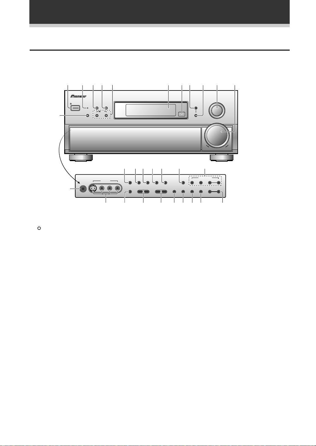
Front Panel
All the controls on the front panel are explained and/or referenced here. To open the front panel push gently on
the lower third of the panel.
12456 7890- =
3
AUDO/ DEO MULTI HANNEL RECE VER
STANDBY/ON
DSP
STANDBY
SGNAL SELECT ADVANCED STANDARD CONTROL
STEREO
MODE
DTS
N∫m /?˘∫
Digital S gnal Processor
~ !@#$ %
5CHANNEL EQUAL POWER OUTPUT
S-VIDEO
PHONES
VIDEO INPUT
VIDEO
L AUDO R
EXTERNAL
DECODER N
¢
1 STANDBY/ON button
Press to switch the receiver ON or into STANDBY
mode.
2 STANDBY indicator
Lights when the receiver is in STANDBY mode.
(Please note that this receiver consumes a small
amount of power (1.0 W) during the standby
mode.)
3 SIGNAL SELECT button (See p.40)
Use to select the signal from the digital
components.
SIGNAL SELECT repeatedly to select one of the
following:
ANALOG : To select an analog signal.
DIGITAL : To select a optical or electrical digital
signal.
4 DSP MODE button (See p.37-38)
Press repeatedly to select a DSP sound mode.
(HALL 1, HALL 2, JAZZ, DANCE, THEATER 1, or
THEATER 2). Use these modes to produce
surround sound from standard (two channel)
stereo sources and create different listening
environments.
DIRECT OUDNESS MIDN GHT
–
BASS +
MULTIROOM
& SOURCE
DOWN UP
NPUT
SELECTOR
MASTER
VOLUME
^
TUNER CONTROL
DIGTAL
– TREBLE +
FL
DMMER
NR CLASS FM/AM
TAPE 2
MONTOR
MEMORYMPXINPUT ATTSPEAKERS
– TUNNG +
– STATION +
&*()_+¡™£
6 2/DTS buttons (See p. 36, 38 & 77-78)
ADVANCED THEATER : Press to select one of
the four Advanced Theater modes.
STANDARD : Press for pure decoding of multi
channel sources.
7 Display (See page 18)
8 Remote sensor
Point the remote control toward the remote
sensor to operate the receiver.
9 MULTI-ROOM & SOURCE button (See
p.72-76)
Press to enable multi room operation (requires an
optional PIONEER Multi-Room Remote Sensor
Unit MR-100 or other IR receiver).
0 CONTROL button (See p.72-76)
Use to select the function or volume of the
MULTI ROOM system.
20
5 STEREO button (See p.37-38)
Press to select the STEREO sound mode. In this
mode, sound comes from the front (left and right)
speakers only.

Displays & Controls
- INPUT SELECTOR dial
Turn to select a source component. The source
indicators show the current component:
DVD/LD : DVD player or Laser Disc player.
TV/SAT : TV tuner or satellite tuner.
CD : Compact Disc player.
MD/TAPE 1 : Tape deck or Mini Disc recorder
connected to MD/TAPE 1 inputs/outputs.
TUNER : The built-in tuner.
PHONO : Turntable.
VIDEO : Video camera (etc.) connected to the
VIDEO INPUT on the front panel.
VCR 1 : Video cassette recorder connected to
VCR 1 inputs.
VCR 2 : Video cassette recorder or other
component connected to VCR 2 inputs.
= MASTER VOLUME
Adjusts the overall receiver volume.
~ EXTERNAL DECODER IN (See p.43)
Use to hook up an external component that can
decode other types of signals and input them into
the VSX-D908S.
! DIRECT button
Switches DIRECT playback on or off. Use to
bypass the tone controls and channel level for the
most accurate reproduction of a program source.
It will automatically put the receiver in STEREO
mode for the function being used for DIRECT
playback.
@ LOUDNESS button (See p.44)
Switches the LOUDNESS mode on or off.
( MPX button (See p.46)
Press to switch between auto stereo and MONO
reception of FM broadcasts. When the broadcast
signal is weak, selecting MONO will improve the
sound quality.
) TAPE 2 MONITOR button (See p.62)
Selects the tape deck (MD recorder, etc.)
connected to the TAPE 2 MOINTOR inputs/
outputs. Allows monitoring of a recording as it’s
being made.
_ INPUT ATT button
Use to lower the input level of an analog signal
that is too powerful, thus causing the receiver to
distort (the overload indicator will light furiously).
+ TREBLE (–/+) button (See p.44)
Use to adjust the high frequencies.
¡ BASS (–/+) button (See p.44)
Use to adjust low frequencies.
™ SPEAKERS (A/B) buttons
A is the primary setting. It plays all speakers
hooked up to the A system. A & B setting only
plays the front speakers and the sub-woofer,
multi channel sources will be down-mixed to
these speakers so no sound will be lost. B setting
only plays the front speakers connected to the B
system and multi channel sources will be downmixed to these two speakers.
A A+B OFFB
PREPARATION
# MIDNIGHT button (See p.42)
Switches the MIDNIGHT LISTENING mode on or
off.
$ DIGITAL NR button (See p.41)
Switches the DIGITAL NR on or off (STEREO
mode only).
% FL DIMMER button (See p.45)
Use to adjust the brightness of the main display.
^ TUNER CONTROL button (See p.46-49)
CLASS : Press repeatedly to switch the preset
station classes.
FM/AM : Press to select the AM or FM band.
TUNING –/+ : Use to manually tune to radio
stations.
& STATION –/+ buttons (See p.48-49)
Use to choose programmed radio stations.
* MEMORY button (See p.48)
Press to start the memorization of a preset
station.
£ VIDEO INPUT jacks (See p.9)
S-VIDEO : Video input for connecting a video
camera (etc.), that has an S-Video out.
VIDEO / AUDIO (L/R) : Video input for
connecting a video camera, etc. that has standard
video/audio outputs.
¢ PHONES jack
Connect headphones for private listening (no
sound will be heard through the speakers)
21
Displays & Controls
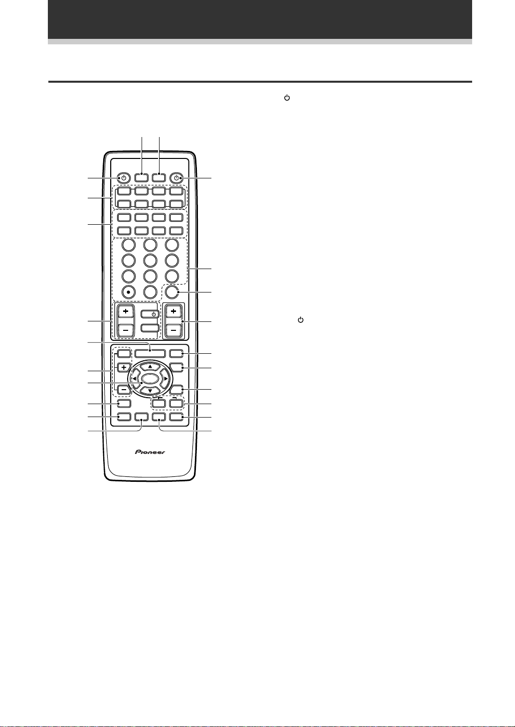
Remote Control
These pages describe the buttons on the remote
control used to operate the receiver.
-=
Î
RECEIVER
SYSTEM
OFF
VCR1 VCR2
TUNER
TV CONT
DIRECT ACCESS
BAND
8
STATION
-
+
CHANNEL
-
+
EX T
ENTER
DISC+10
VOLUME
MUTE
FUNCTION
SIGNAL
SELECT
2/dts
ADVANCED STANDARD
STEREO
DSP
DIGITAL NR
~
!
@
#
$
%
^
&
*
(
1
2
3
4
5
6
7
8
9
0
S0URCE
MULTI
OPERATION
DVD/LD TV/SAT
MULTI CONTROL
MD/
CD
TAPE1
CLASS MPX
73
TUNING
-
+
1¡4¢
DTV ON/OFF DTV MENU
GU DE
/CH SEL
23
1
56
4
89
7
0
TV
TV CONTROL
TV VOL
TV FUNC
EFFECT
MENU
ENTER
SYSTEM
SETUP
REMOTE
M DNIGHT
SETUP
D GITAL MULTI PROCESSING AMPLIFER
REMOTE CONTROL UN T
1 SOURCE button (See p.54-61)
Use to turn on the power of your other
components after you have recalled or taught the
signals to this remote control.
2 MULTI CONTROL buttons
Use these to select a source and the
corresponding remote operation mode.
For example, pressing TUNER selects the built in
tuner and sets the remote operation to the tuner
functions.
3 Component Control buttons
Use to control specific components, like a CD
player or DVD player, after you have programmed
the remote control to do these operations (see
p.54-61) and the remote is put in that operation
mode.
4 TV CONTROL buttons
The following buttons are used to control the TV
only and can be used no matter what function the
remote control is set to.
TV
: Press to turn the power of the TV on/off.
TV FUNC : Press TV FUNC to select the TV for
remote control operation.
TV VOL +/– : Press to control the volume of the
TV.
5 MENU button
Use to get the various menus for your TV or DVD.
6 EFFECT/CH SEL +/– buttons (See p.38)
EFFECT : Use these buttons to increase or
decrease the amount of effect applied in a DSP or
Advanced Theater mode. When the amount of
effect is increased in a DSP/Advanced Theater
mode the characteristics of that mode become
stronger and more noticeable. The scale ranges
from 10-90 with 70 as the default setting. First
turn on the DSP/Advanced Theater you want (by
pressing the DSP/Advanced Theater button until
you get the mode) and then increase or decrease
the amount of effect.
CH SEL : You may want to adjust the channels
when listening to some sound sources. Use this
button to select the channel you want to adjust.
+/– : Use these buttons to select the amount of
effect in a sound mode and to adjust the channel
level when making surround sound settings.
22
7 5/∞/2/3/ENTER buttons
Use to operate the on-screen menu on your TV
screen and enter commands when setting up
surround sound, speakers levels & settings, and
other set up features see p.24-34). Specific use
of these buttons is described in conjunction with
the operations they perform. For more
information see each individual section.

Displays & Controls
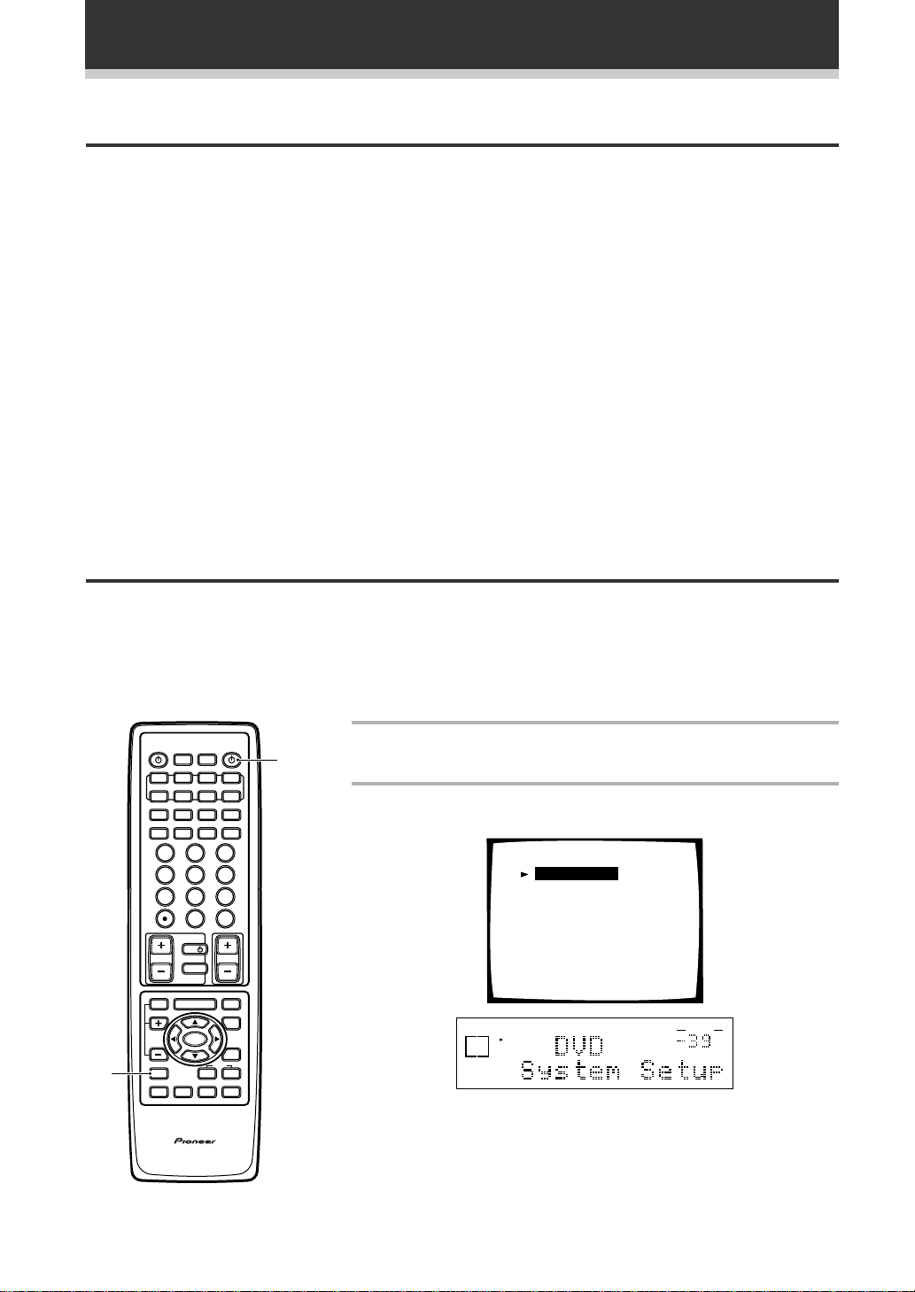
8 SYSTEM SET UP button
Use to set up the speaker and sound systems.
For more information see “Surround Sound
Setup” starting on p. 24.
9 REMOTE SETUP button.
Use to customize the remote control functions
and the remote control itself. (See “Setting Up
the Remote Control to Control Other
Components” starting on p.50, “Multi
Operation” starting on p. 65.)
To access the EXTERNAL DECODER option,
press the REMOTE SETUP button and the
SIGNAL SELECT button simultaneously.
0 MIDNIGHT button (See p. 42)
Switches the MIDNIGHT LISTENING mode on or
off.
- MULTI OPERATION button
Use this button to start the MULTI OPERATION
mode. See p. 65 for how to program and use the
MULTI OPERATION mode.
= SYSTEM OFF button
This button turns off components in two ways.
First, when pressed it will turn off all PIONEER
components. Secondly, any component that has
programmed into the MULTI OPERATIONS
settings will also be turned off. (see p. 67).
For example : If you programmed power on for
your TV and VCR, pressing the SYSTEM OFF
button will turn off these components even if
they are not PIONEER products.
^ SIGNAL SELECT button
Press SIGNAL SELECT repeatedly to select one
of the following:
ANALOG : To select an analog signal.
DIGITAL : To select a digital signal (DVD/LD,
TV/SAT, CD, MD/TAPE 1, VCR 1, VCR 2).
Press the SIGNAL SELECT and REMOTE SETUP
buttons simultaneously to switch from the
SIGNAL SELECT operation to EXTERNAL
DECODER operation. Then press the button to
get the EXTERNAL DECODER function. To get
back to the SIGNAL SELECT control, press the
REMOTE SETUP button and the SIGNAL SELECT
button simultaneously once again.
& 2/dts buttons (See p.38)
Press these buttons to put the receiver in the
selected sound mode. For more information on
the modes .
* STEREO/DIGITAL NR button
STEREO : Press this button to put the receiver
into stereo mode when it’s in a different sound
mode. For more information on the sound modes
see p.38.
DIGITAL NR : Switches the DIGITAL NR on or off
(see p.41).
( DSP button (See p.38)
Press repeatedly to select a DSP sound mode.
PREPARATION
~ RECEIVER button
Press to turn power of the receiver on or to
STANDBY (off).
! Number buttons
These buttons can perform a variety of different
functions depending on the remote operation
mode. They are most useful for CD and tuner
operations.
@ ENTER/EXIT/DISC button
These buttons can perform a variety of different
functions depending on the remote operation
mode.
# MASTER VOLUME button
Use to raise or lower the volume of the receiver.
$ MUTE button
Press to mute or restore the volume.
% FUNCTION button
Press to select a source. The button will cycle
through all the possible sources.
23
Surround Sound Set Up
On Screen Display
There are a number of possible ways to hook up the receiver to your video components, like a DVD player, and
hook up to your receiver to your TV, but some of them won't allow you to use the on-screen display of this unit.
To avoid this one simply needs to follow two rules.
1 Always use the same type of video cords to hook up your video components to the receiver as you use to
hook up the receiver and your TV. For example, if you use composite video cords to hook up your DVD and
the receiver, use composite video cords to hook up the receiver to your TV. If you use S video cords to hook
up your DVD and the receiver, use S video cords to hook up the receiver to your TV.
2 Always make sure your TV is set to the appropriate input channel (for example, video 1). Your TV may have a
number of input channels and if you don't select the proper one you won't be able to use this receiver's onscreen display, or, in fact, see any picture from this receiver at all. If you are unsure how to choose an input
channel for your TV, refer to the manual which came with your TV.
You might, for example, use both composite and S video cords to hook up your video components with this
receiver and then use composite video cords to hook up this receiver to your TV. This arrangement would still
NOT let you see the on screen displays from this receiver on your TV. The best idea is just to use one type of
video cord for all your video component and TV hook ups.
Setting Up for Surround Sound
To ensure the best possible surround sound, be sure to complete the following set up operations. This is
particularly important when using the DTS, 2 (Dolby) Surround sound modes. You only need to make these
settings once (unless you change the placement of your current speaker system or add new speakers, etc.).
These set up operations use your TV to display the settings and choices so be sure your TV and receiver are
properly hooked up.
2
S0URCE
DVD/LD TV/SAT
CD
CLASS MPX
TUNING
-
1¡4¢
DTV ON/OFF DTV MENU
1
4
7
GUIDE
TV VOL
EFFECT
/CH SEL
SYSTEM
SETUP
REMOTE
SETUP
DIGITAL MULTI PROCESSING AMPLFIER
MU TI
SYSTEM
OPERATON
VCR1 VCR2
MULTI CONTROL
MD/
TUNER
TAPE1
BAND
73
+
23
56
89
0
TV
TV CONTROL
TV FUNC
MENU
ENTER
ADVANCED STANDARD
M DN GH
DSP
REMOTE CONTROL UNT
OFF
-
-
RECEIVER
DRECT ACCESS
STATION
CHANNEL
ENTER
VOLUME
2/dts
DIGITAL NR
TV CONT
8
+
+
MUTE
FUNCTON
SGNAL
SELECT
STEREO
Î
1
EXT
DSC+10
1
Turn on the receiver and your TV.
Make sure your TV is set to the receiver.
2
Press SYSTEM SETUP button.
The SYSTEM SETUP MENU appears on your TV screen.
System Setup
[Speaker Setting]
[Channel Delay]
[Channel Level]
[Crossover Network]
[Bass Peak Level Manager]
[D-Range Control]
[Digital-In Select]
[Multi-Room]
SIGNAL
SELECT
ANALOG
AUTO
A
SP
STEREO
VOLUME
dB
* You can escape from this screen at any time by pressing the
SYSTEM SETUP button again. None of the settings you made will
be entered in this case.
24
Surround Sound Set Up
3
S0URCE
DVD/LD TV/SAT
CD
SS
TUNNG
-
1¡4¢
DTV ON/OFF DTV MENU
1
4
7
GUIDE
TV VOL
EFFECT
CH SEL
SYSTEM
SETUP
REMOTE
SETUP
DIGITAL MULTI PROCESSING AMPLIFIER
MULTI
SYSTEM
OPERATON
VCR1 VCR2
MULTI CONTROL
MD/
TUNER
TAPE1
73
+
23
56
89
0
TV
TV CONTROL
TV FUNC
MENU
ENTER
DVANCED STANDAR
M DN GHT
DSP
REMOTE CONTROL UNT
OFF
-
-
RECEIVER
DR ESS
STATION
CHANNEL
ENTER
VOLUME
2/dts
D GITAL NR
TV CONT
8
+
+
MUTE
FUNCTON
SGNAL
SELECT
STEREO
Î
3
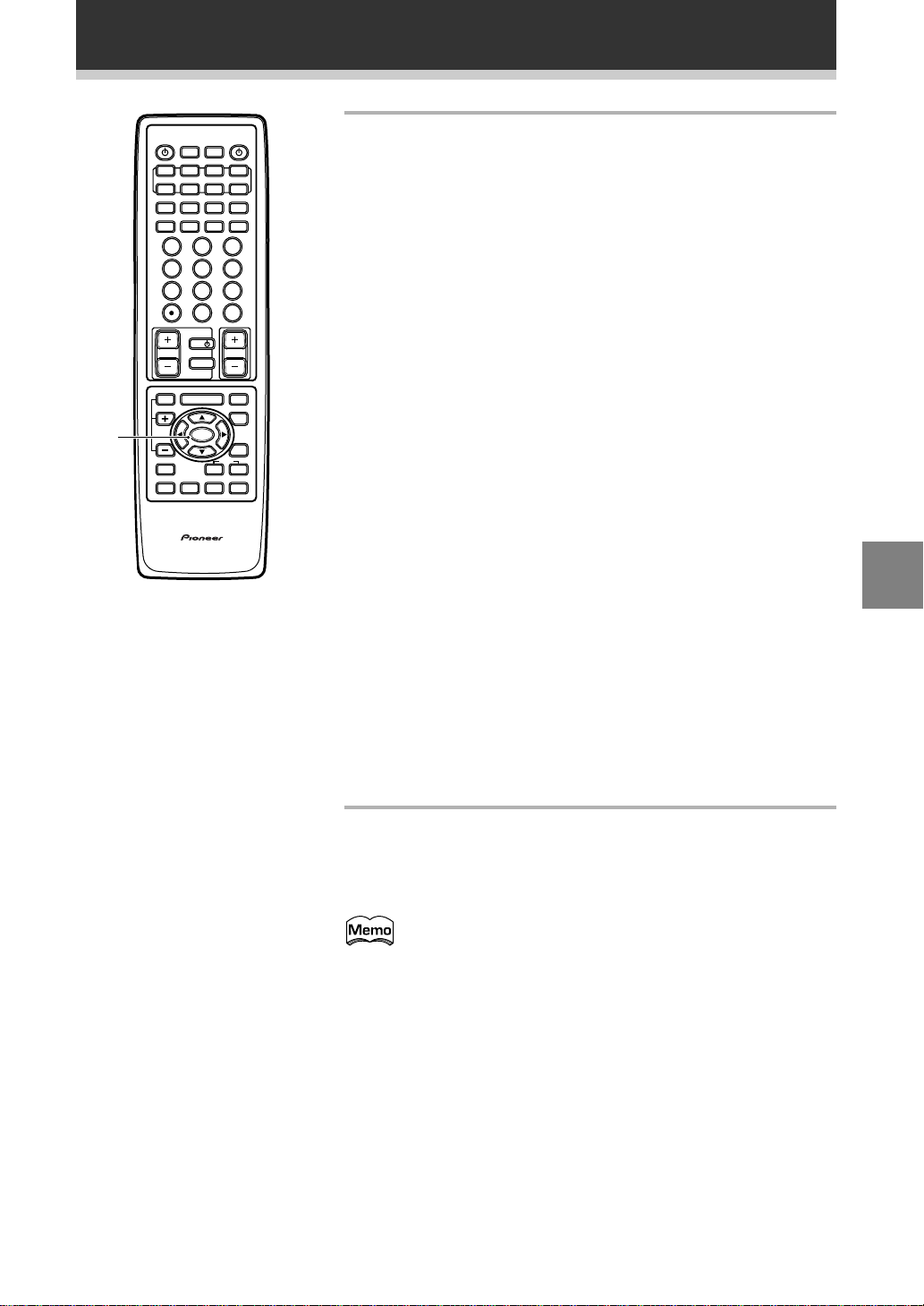
Press the 5 or ∞ arrow buttons to move the hand to
the mode you want. Then press ENTER.
In each mode, the current settings are displayed automatically. We
suggest you adjust all these settings when you first hook up the
receiver. That gets them out of the way and you won’t need to
return to this setting mode unless you change your home set up by
adding new speakers (etc.). The sound set up modes explained
here are:
EXT
DISC+10
Speaker Setting (See p.26-27)
Use to specify the type and number of speakers you connected.
Channel Delay (See p.28)
Set up all your speakers for the most realistic surround sound.
Adding a slight delay to some speakers enhances sound separation
and is particularly important for achieving a surround sound effect.
You need to figure out the distance from your listening position to
your speakers to add the proper delay.
CHannel Level (See p.29-30)
Use to balance the volumes of your different speakers.
Crossover Network (See p.31)
This feature lets you select which bass frequencies will be sent to
the sub woofer or front speakers.
Bass Peak Level Manager (See p.32)
Dolby Digital and DTS audio sources include ultra-low bass tones.
Set the bass peak level as needed to prevent the ultra-low bass
tones from distorting the sound from the speakers.
D-Range Control (See p.33)
This feature makes possible excellent surround sound effects
when listening to Dolby Digital sources at low volumes.
Digital-In Select (See p.34)
In order to use your digital components you must match the
numbered digital input buttons with the numbered digital jacks
used by your digital components.
Multi-Room (See p.72-76)
You can set up this unit to power systems in different rooms.
UP
SET
4
Go on to the next page to continue set up.
To exit the SYSTEM SETUP MENU and on-screen display press
SYSTEM SET UP button again.
After you complete one of the SYSTEM SETUP menus and
return to the basic SYSTEM SETUP screen (shown in the
diagram directly above labeled 4), the receiver automatically
moves the cursor to the next SYSTEM SETUP menu. For
example, if you’ve completed SPEAKER SETTING and returned
to the basic SYSTEM SETUP screen, CHANNEL DELAY will be
selected automatically. You can notice this on your TV screen.
25
Surround Sound Set Up
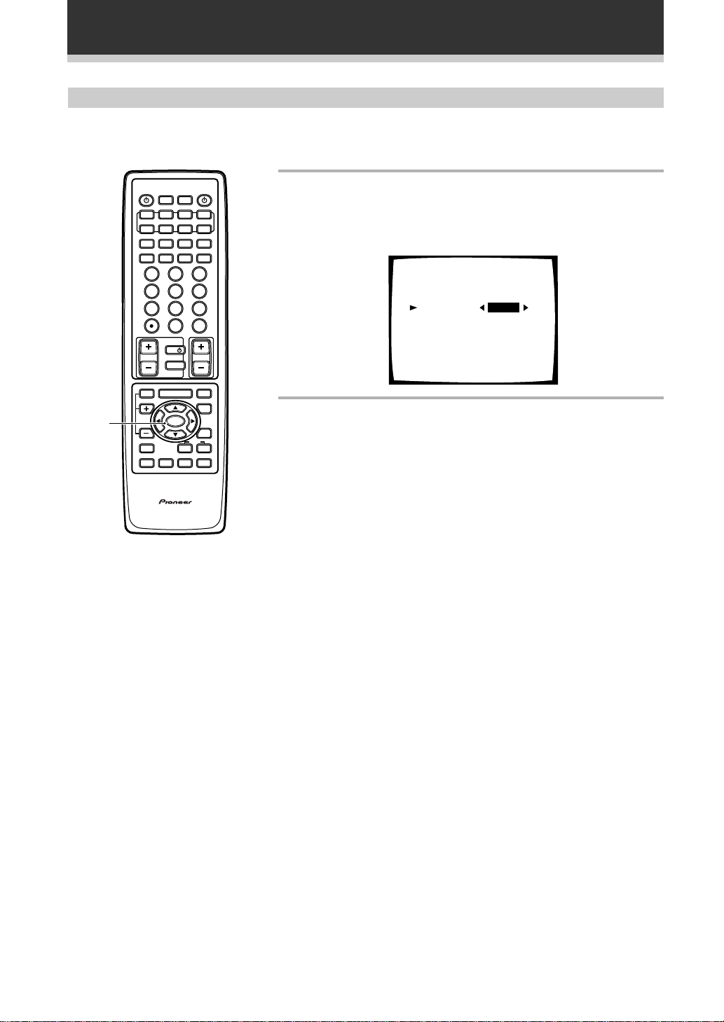
Speaker Setting
The following steps show you how to specify the type of speakers you connected. Use the 5¥∞ and 2¥3 arrow
buttons to make a selection within the on-screen menus, and use the enter to register the information.
1,2
S0URCE
DVD/LD TV/SAT
CD
CLASS MPX
TUNING
-
1¡4¢
DTV ON/OFF DTV MENU
1
4
7
GUIDE
TV VOL
EFFECT
/CH SEL
SYSTEM
SETUP
REMOTE
SETUP
DIGITAL MULTI PROCESSING AMPLFIER
MU TI
SYSTEM
OPERATO
VCR1 VCR2
MULTI CONTROL
MD/
TUNER
TAPE1
BAND
73
+
23
56
89
0
TV
TV CONTROL
TV FUNC
MENU
ENTER
ADVANCED TANDARD
M DN GH
DSP
REMOTE CONTROL UNT
OFF
-
-
RECEIVER
DIRECT ACCESS
STATON
CHANNEL
ENTER
VOLUME
2/dts
DIGITAL NR
TV CONT
8
+
+
MUTE
UNCTON
SGNAL
SELECT
STEREO
Î
1
Select SPEAKER SETTING with the 5¥∞ buttons.
See “Setting Up for Surround Sound” on page 24 if you are unsure
how to do this.
Press ENTER.
Speaker Setting
EXIT
DSC+10
Front
Center
Surround
Subwoofer
[LARGE]
[LARGE]
[LARGE]
[ YES ]
[EXIT]
2
Select a speaker setting mode with the 2¥3 buttons.
Press the ∞ button.
26
 Loading...