

Pioneer VSXD-510 Service manual
TONE
DOWN UP
1
R
MULTI JOG
MASTER
VOLUME
N∫m-Û.,? Digital Signal Processor
STATION
STANDBY
STANDBY/ON
PHONES
TUNING
CLASS MEMORY BAND MPX SPEAKERS MIDNIGHT
SIGNAL
DVD
DSP
DIRECT
MONITOR
/DTS
SELECT
5.1CH
MODE
AUDIO/VIDEO MULTI-CHANNEL RECEIVER
VSX-D510
THIS MANUAL IS APPLICABLE TO THE FOLLOWING MODEL(S) AND TYPE(S).
Type
MYXJIEW AC220-230V
MYXJIGR AC220-230V
MVXJI AC230V
Model
VSX-D510
Power Requirement Remarks
ORDER NO.
RRV2439
CONTENTS
1. SAFETY INFORMATION
2. EXPLODED VIEWS AND PARTS LIST
3. BLOCK DIAGRAM AND SCHEMATIC DIAGRAM
4. PCB CONNECTION DIAGRAM
5. PCB PARTS LIST
6. ADJUSTMENT
...............................................
....................................................
PIONEER CORPORATION 4-1, Meguro 1-chome, Meguro-ku, Tokyo 153-8654, Japan
PIONEER ELECTRONICS SERVICE, INC. P.O. Box 1760, Long Beach, CA 90801-1760, U.S.A.
PIONEER EUROPE NV Haven 1087, Keetberglaan 1, 9120 Melsele, Belgium
PIONEER ELECTRONICS ASIACENTRE PTE. LTD. 253 Alexandra Road, #04-01, Singapore 159936
c
PIONEER CORPORATION 2001
......................................
...............
.....
.........................
26
39
46
2
3
8
7. GENERAL INFORMATION
7.1 DISASSEMBLY and DIAGNOSIS
7.2 PARTS
7.2.1 IC
7.2.2 DISPLAY
..........................................................
............................................................
.................................................
8. PANEL FACILITIES AND SPECIFICATIONS
................................
................
47
47
49
49
54
.......
56
T – ZZR MAR. 2001 Printed in Japan
VSX-D510
1. SAFETY INFORMATION
This service manual is intended for qualified service technicians ; it is not meant for the casual do-ityourselfer. Qualified technicians have the necessary test equipment and tools, and have been trained
to properly and safely repair complex products such as those covered by this manual.
Improperly performed repairs can adversely affect the safety and reliability of the product and may
void the warranty. If you are not qualified to perform the repair of this product properly and safely, you
should not risk trying to do so and refer the repair to a qualified service technician.
WARNING
This product contains lead in solder and certain electrical parts contain chemicals which are known to the state of California to cause
cancer, birth defects or other reproductive harm.
NOTICE
(FOR CANADIAN MODEL ONLY)
Fuse symbols (fast operating fuse) and/or (slow operating fuse) on PCB indicate that replacement parts must
be of identical designation.
REMARQUE
(POUR MODÈLE CANADIEN SEULEMENT)
Les symboles de fusible (fusible de type rapide) et/ou (fusible de type lent) sur CCI indiquent que les pièces
de remplacement doivent avoir la même désignation.
Health & Safety Code Section 25249.6 – Proposition 65
(FOR USA MODEL ONLY)
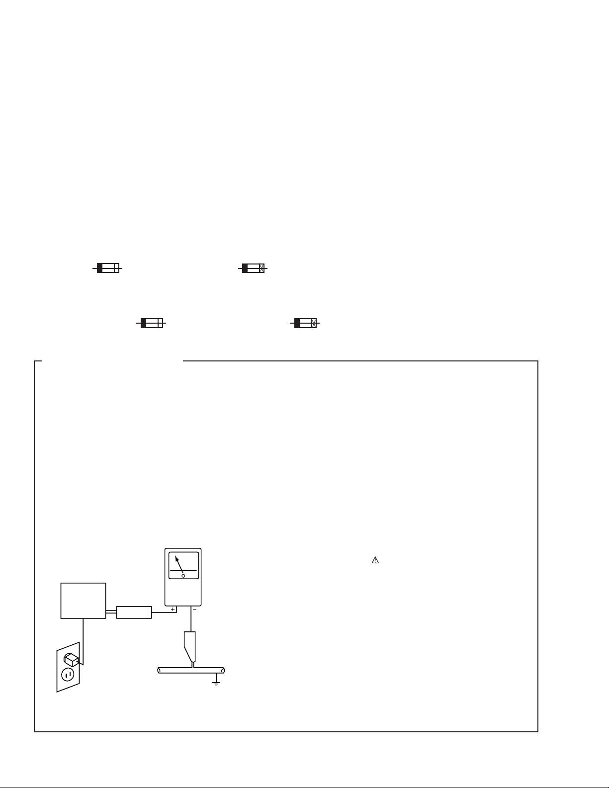
1. SAFETY PRECAUTIONS
The following check should be performed for the
continued protection of the customer and service
technician.
LEAKAGE CURRENT CHECK
Measure leakage current to a known earth ground (water
pipe, conduit, etc.) by connecting a leakage current tester
such as Simpson Model 229-2 or equivalent between the
earth ground and all exposed metal parts of the appliance
(input/output terminals, screwheads, metal overlays, control
shaft, etc.). Plug the AC line cord of the appliance directly
into a 120V AC 60Hz outlet and turn the AC power switch
on. Any current measured must not exceed 0.5mA.
Reading should
not be above
0.5mA
Earth
ground
Device
under
test
Also test with
plug reversed
(Using AC adapter
plug as required)
Test all
exposed metal
surfaces
Leakage
current
tester
ANY MEASUREMENTS NOT WITHIN THE LIMITS
OUTLINED ABOVE ARE INDICATIVE OF A POTENTIAL
SHOCK HAZARD AND MUST BE CORRECTED BEFORE
RETURNING THE APPLIANCE TO THE CUSTOMER.
2. PRODUCT SAFETY NOTICE
Many electrical and mechanical parts in the appliance
have special safety related characteristics. These are
often not evident from visual inspection nor the protection
afforded by them necessarily can be obtained by using
replacement components rated for voltage, wattage, etc.
Replacement parts which have these special safety
characteristics are identified in this Service Manual.
Electrical components having such features are identified
by marking with a
in this Service Manual.
The use of a substitute replacement component which does
not have the same safety characteristics as the PIONEER
recommended replacement one, shown in the parts list in
this Service Manual, may create shock, fire, or other hazards.
Product Safety is continuously under review and new
instructions are issued from time to time. For the latest
information, always consult the current PIONEER Service
Manual. A subscription to, or additional copies of, PIONEER
Service Manual may be obtained at a nominal charge from
PIONEER.
on the schematics and on the parts list
AC Leakage Test
2
2. EXPLODED VIEWS AND PARTS LIST
NOTES:• Parts marked by "NSP" are generally unavailable because they are not in our Master Spare Parts List.
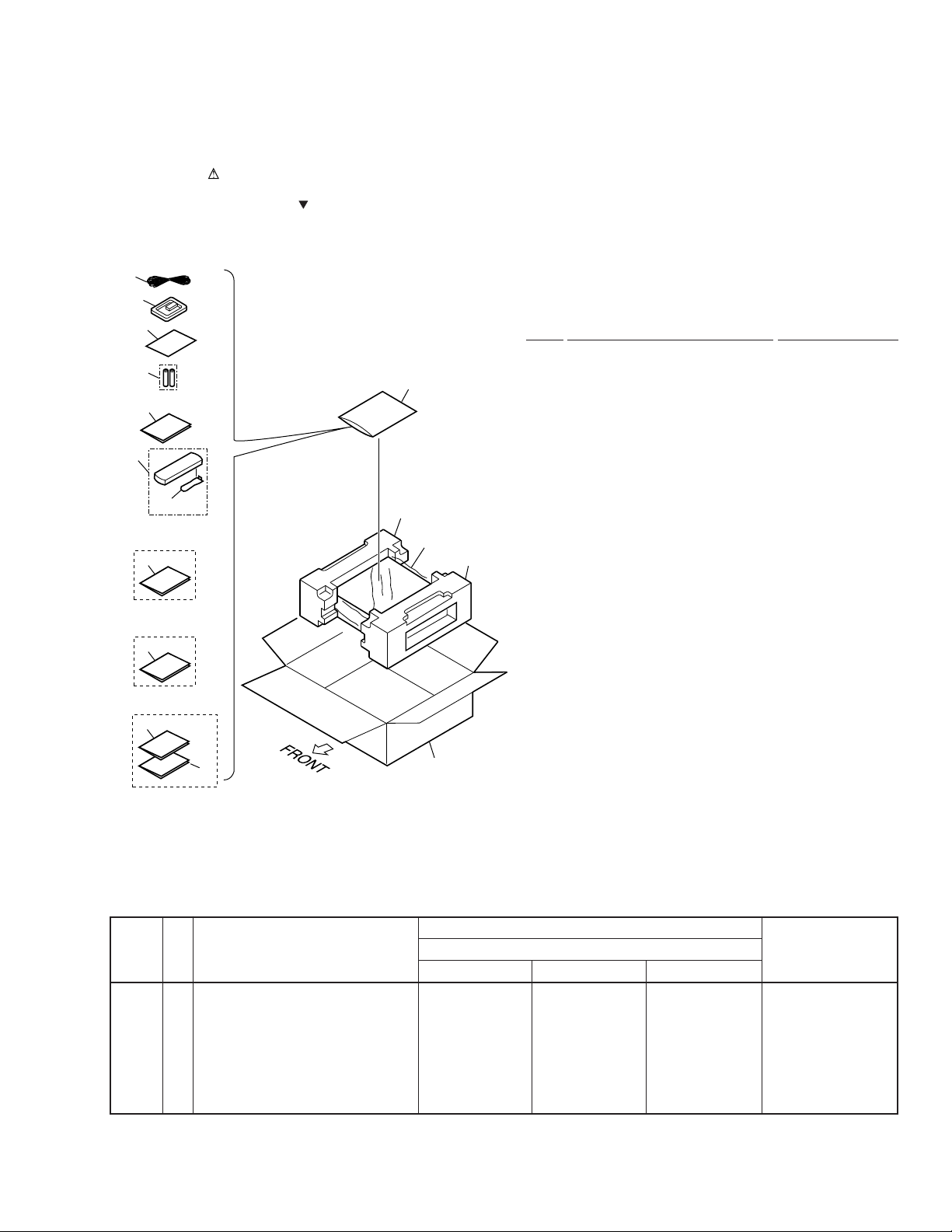
2.1 PACKING
1
The mark found on some component parts indicates the importance of the safety factor of the part.
•
Therefore, when replacing, be sure to use parts of identical designation.
Screws adjacent to mark on the product are used for disassembly.
•
2
4
(1) PACKING PARTS LIST
Mark No. Description Part No.
VSX-D510
7
12
5
6
MYXJIEW and
MVXJI Types Only
12
MYXJIEW and
MYXJIGR Types Only
13
MYXJIEW Type Only
14
15
1 FM Wire Antenna ADH7005
3
8
10
9
11
NSP 3 Polyethylene Bag Z21-038
NSP 4 Warranty Card ARY7022
NSP 7 Dry Cell Battery (R6P, AA) VEM1011
2 AM Loop Antenna ATB7009
(0.03 × 230 × 340)
5 Remote Control Unit AXD7247
6 Battery Cover AZA7378
8 Left Pad XHA3024
9 Right Pad XHA3025
10 Packing Sheet AHG7069
11 Packing Case XHD3149
12 Operating Instructions See Contrast table (2)
(English)
13 Operating Instructions See Contrast table (2)
(German)
14 Operating Instructions See Contrast table (2)
(Dutch/Swedish/Portuguese)
15 Operating Instructions See Contrast table (2)
(French/Italian/Spanish)
(2) CONTRAST TABLE
VSX-D510/MYXJIEW, /MYXJIGR and VSX-D510/MVXJI are constructed the same except for the following:
Part No.
Mark
No.
12 Operating Instructions (English) XRB3003 Not used XRB3003
13 Operating Instructions (German) XRC30027 XRC3027 Not used
14 Operating Instructions XRC3028 Not used Not used
15 Operating Instructions XRC3029 Not used Not used
Symbol and Description
(Dutch/Swedish/Portuguese)
(French/Italian/Spanish)
VSX-D510
/MYXJIEW /MYXJIGR /MVXJI
Remarks
3
VSX-D510
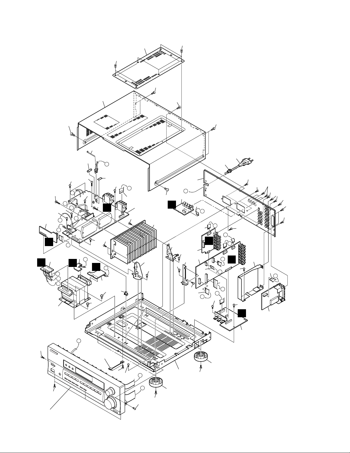
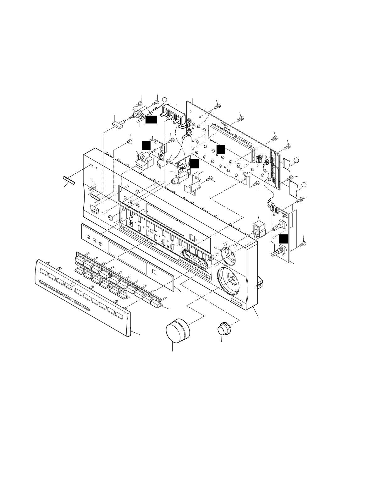
2.2 EXTERIOR SECTION
25
39
43
D
11
37
36
38
36
3
F
9
J
36
G
H
37
M
K
L
D
8
J
G
M
L
K
10
C
39
38
36
I
35
B
36
H
6
39
22
36
34
17
J
29
36
36
41
36
22
26
36
19
18
36
36
36
E
36
27
36
36
15
36
7
36
36
36
36
F
24
I
42
N
E
36
16
14
H
2
1
13
D
36
N
F
E
A
A
12
B
C
31
36
C
39
4
36
30
28
36
5
G
36
36
Refer to
"2.3 FRONT PANEL SECTION".
Accessory of
Front Panel
36
36
36
32
A
B
36
23
32
36
4
VSX-D510
(1) EXTERIOR SECTION PARTS LIST
Mark No. Description Part No. Mark No. Description Part No.
1 D.D & INPUT Assy XWX3025
2 VIDEO&6CH IN Assy XWZ3333
NSP 3 AMP INPUT Assy AWX7382
4 AMP&PRIMARY Assy XWZ3373
5 REGULATOR Assy AWX7493
6 TRANS 2 Assy AWX7468
7 FM/AM TUNER Unit AXX7048
NSP 8 TRANS 1 Assy AWX7390
NSP 9 TRANS 3 Assy AWX7392
10 Power Transformer (AC230V) ATS7259
11 Fuse (FU1 : T2.5A) REK1026
12 FFC (J31 : 31P/180 BD 60V) XDD3055
(D.D & INPUT CN102
↔ FRONT CN402)
13 FFC (J32 : 19P/180 BD 60V) XDD3054
(D.D & INPUT CN103
↔ FRONT CN401)
14 FFC (J33 : 14P/200 BD 60V) XDD3060
(D.D & INPUT CN104
↔ VIDEO&6CH IN CN303)
15 FFC (J34 : 13P/100 BD 60V) XDD3059
(D.D & INPUT CN105
↔ FM/AM TUNER CN1)
16 FFC (J35 : 17P/90 BD 60V) XDD3072
(D.D & INPUT CN106
↔ AMP INPUT CN290)
17 FFC (J36 : 22P/80 BD 60V) XDD3057
(REGULATOR CN801
↔ AMP&PRIMARY CN53)
18 Strain Relief CM-22B
19 AC Power Cord See Contrast table (2)
20 • • • • •
NSP 23 Under Base 409 ANA7094
NSP 30 Heat Sink Assy 0.8 ANH7118
NSP 35 Fuse Card AAX7277
21 • • • • •
22 Push Rivet AEC7025
24 Rear Panel XNC3080
25 Bonnet Case XZN3111
26 PCB Angle ANG7253
27 Shield R3 ANG7277
28 Heat Sink Angle F ANG7251
29 Heat Sink Angle R ANG7252
31 Top Cover XME3001
32 Insulator PNW2766
33 • • • • •
34 PCB Mold AMR2533
36 Screw BBZ30P080FMC
37 Screw BBZ30P200FMC
38 Screw (3x23) ABA7043
39 Screw FBT40P080FZK
40 • • • • •
41 DIGITAL IN Assy XWZ3361
42 FFC (J37 : 6P/130 BD 60V) XDD3058
(D.D & INPUT CN1501
↔ DIGITAL IN CN1901)
43 Binder ZCA–BK1
(2) CONTRAST TABLE
VSX-D510/MYXJIEW, /MYXJIGR and VSX-D510/MVXJI are constructed the same except for the following:
Part No.
No.
Mark Remarks
19 AC Power Cord VDG1077 VDG1077 VDG1076
Symbol and Description
VSX-D510
/MYXJIEW /MYXJIGR /MVXJI
5
VSX-D510
2.3 FRONT PANEL SECTION
19
10
13
9
16
5
M
GA
2
16
G
16
17
1
20
I
4
16
16
16
16
K
A
8
16
16
16
B
16
14
15
16
L
3
18
7
6
11
12
6

FRONT PANEL SECTION PARTS LIST
•
Mark No. Description Part No.
1 FRONT Assy XWZ3337
NSP 3 R. ENCODER Assy XWZ3353
NSP 4 H.P. Assy XWZ3356
2 POWER SW Assy XWZ3352
5 MECHA SW Assy XWZ3358
6 Front Panel XMB3035
7 Sub Button XAD3068
8 Earth Plate A XNG3044
9 Name Plate PAM1776
10 LED Lens PNW2019
11 Select Knob XAB3008
12 Volume Knob XAB3011
13 Power Button XAD3062
14 Sub Panel XAK3169
15 Jog Button XAD3065
VSX-D510
16 Screw PPZ30P080FMC
17 Screw BBZ30P080FMC
18 Display Panel XAK3171
19 Power Button M AAD7442
20 RDS Button XAD3072
7
1
23
VSX-D510
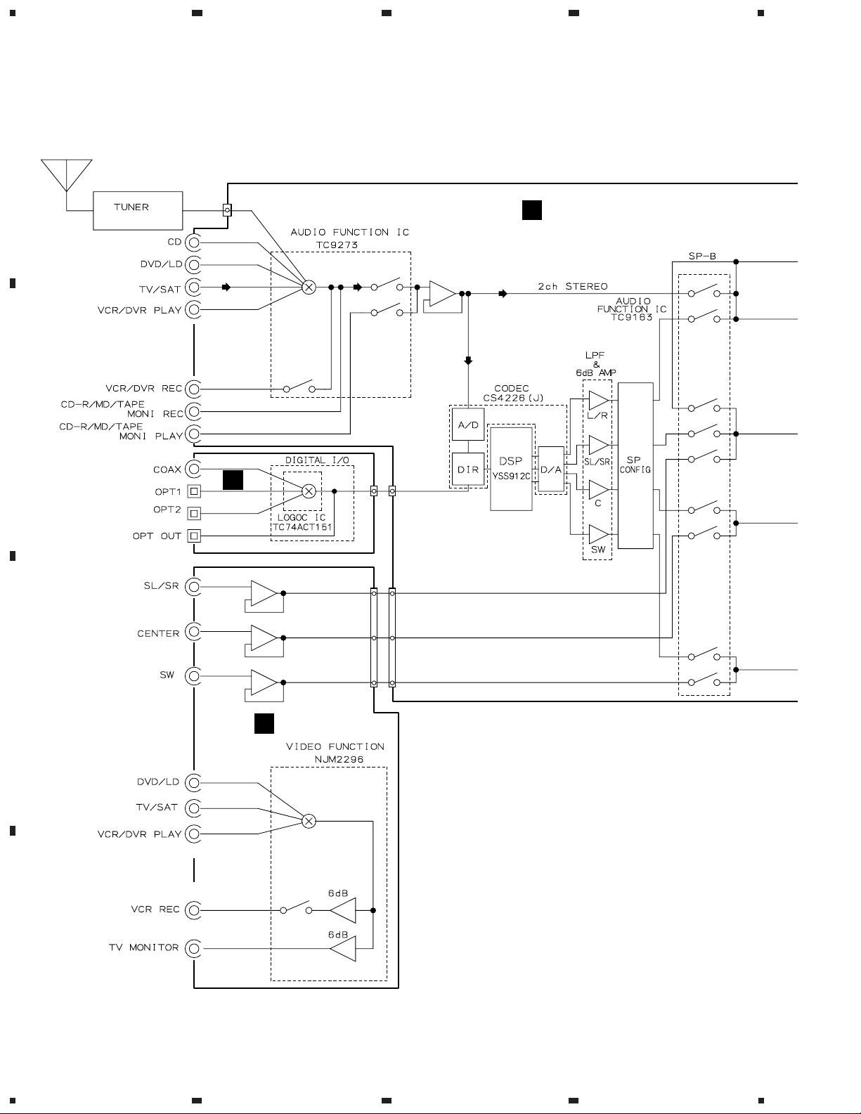
3. BLOCK DIAGRAM AND SCHEMATIC DIAGRAM
A
3.1 BLOCK DIAGRAM
4
UNIT
AXX7048
B
CN105
6
J
DIGITAL
IN ASSY
5
IC101
5
7
2
3
4
11
910
3
25
IC303
7
IC1901
CN19012CN1501
CN305
7
2
CN104
7
D.D & INPUT ASSY
A
IC104
12
3
1
14
42
IC1101
IC1201
DTS DECODER
21
26
67
67
23
25
67
21
IC102
IC1701
IC1703
IC1705
IC1705
3
4
6
8
7
18
19
5
9
17
IC302
5
3
7
IC302
1
11
11
11
9
9
10
12
C
VIDEO & 6CH IN ASSY
H
7
5
9
11
1
IC301
D
8
1234

5
678
VSX-D510
IC108
CN102
57
3
K
J43
551
4
H.P. ASSY
I
A
IC103
Q105
Q551
FRONT ASSY
17
IC105
31
57
15
4
CN106
601
1
Q603
IC601
22
B
15
AMP & PRIMARY ASSY
RY751
(FRONT L)
F
Q601
9
11
IC106
34
57
33
IC107
5 7
10 5
AMP INPUT ASSY
69
Q653
Q651
IC602
24
18
26
IC602
14
RY753
RY752
B
Q632
6
36
Q631
C
VSX-D510
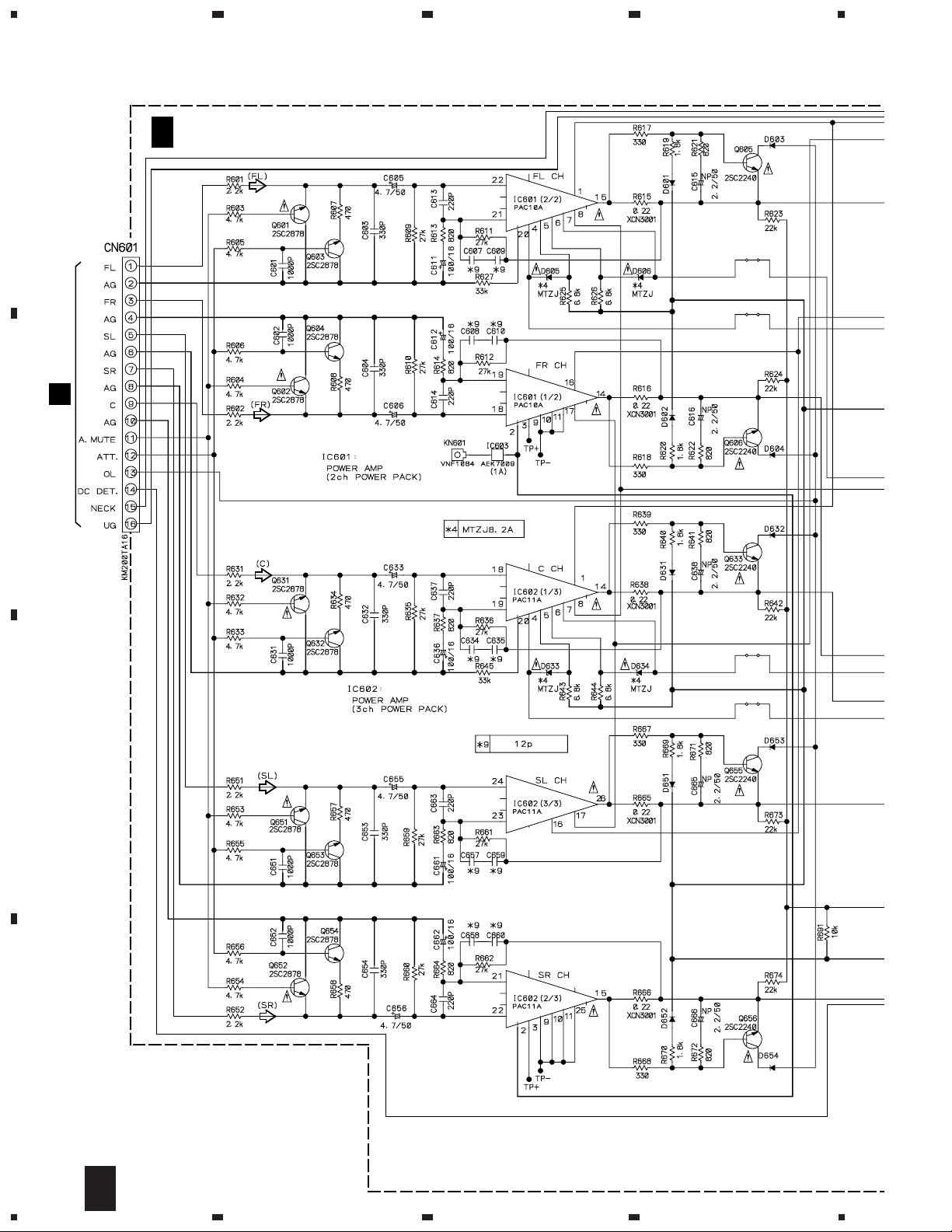
AMP & PRIMARY ASSY
B
POWER AMP
IC601, IC602
CN402
K
CN101
A
CN101
A
+BVH
-BVH
NECK+B
NECK-B
+BVL
-BVL
FL AC
FL AC
+12V
-12V
D+5V
A+5V
Q701
Q702
IC801
IC802
IC803
IC804
31
IC107
Q112
D701
D702
D801–D804
D805–D808
REGULATOR ASSY
E
CN1041CN305
CN101
A
U+5V
T1
POWER
TRANSFORMER
IC51
RY51
1
VIDEO &
H
6CH IN ASSY
Q303
D51-D54
T51
AMP & PRIMARY ASSY
B
AC IN
D
9
5
6
7
8
1
23
4
VSX-D510
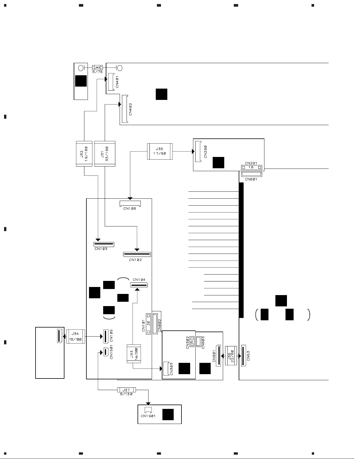
3.2 OVERALL WIRING CONNECTION DIAGRAM and AMP INPUT ASSY
A
R.ENCODER
D15A06-075-2651
511
404
ASSY
(XWZ3353)
L
FRONT ASSY
K
(XWZ3337)
XDD3054
B
XDD3055
XDD3072
F
AMP INPUT ASSY
(AWX7382)
C
A
D.D & INPUT ASSY
(XWX3025)
A 3/3
A 1/3, A 2/3,
B
B 1/2, B 2/2
AMP&PRIMARY ASSY
(XWZ3373)
XDD3057
FM/AM
TUNER
UNIT
(AXX7048)
D
10
1234
XDD3059
XDD3060
XDD3058
H
VIDEO&
6CH IN ASSY
(XWZ3333)
DIGITAL IN ASSY
J
(XWZ3361)
E
REGULATOR ASSY
(AWX7493)
5
678
VSX-D510
Note : When ordering service parts, be sure to refer to "EXPLODED VIEWS and PAR TS LIST" or "PCB PARTS LIST".
A
403
471
D15A04-125-2651
D15A04-070-2651
501
GA
1551
POWER SW ASSY
M
(XWZ3352)
MECHA SW ASSY
(XWZ3358)
I
H.P.
ASSY
(XWZ3356)
D
TRANS3
ASSY
B
(AWX7392)
J7J6
J3
AMP INPUT ASSY
F
(AWX7382)
TRANS2
ASSY
C
(AWX7468)
851
J4J5
D20PYY0715E
701
G
J1J2
TRANS1 ASSY
(AWX7390)
52
CN106
A 1/3
CN601
C
B 1/2
D
AC CORD
F
5
6
7
8
11
1
23
VSX-D510
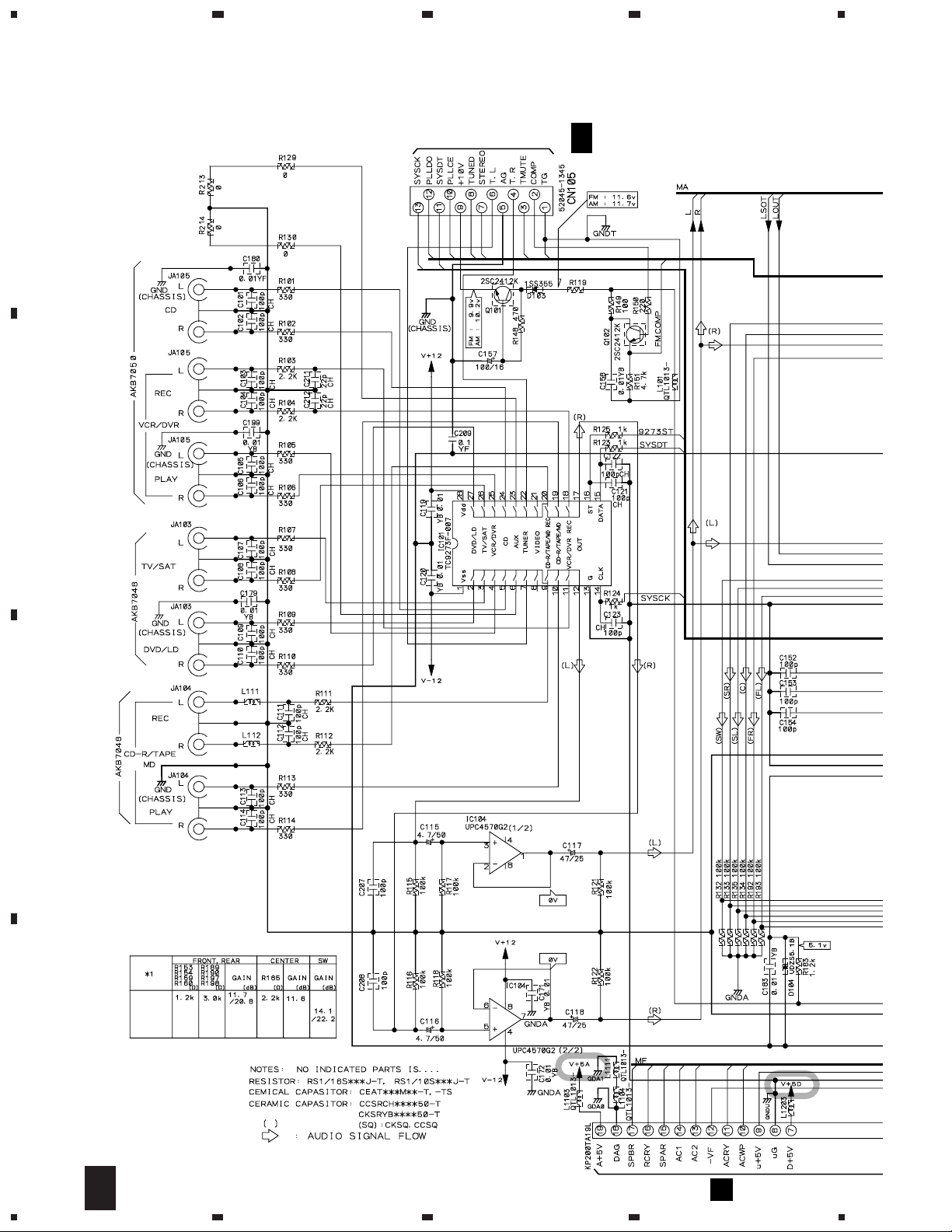
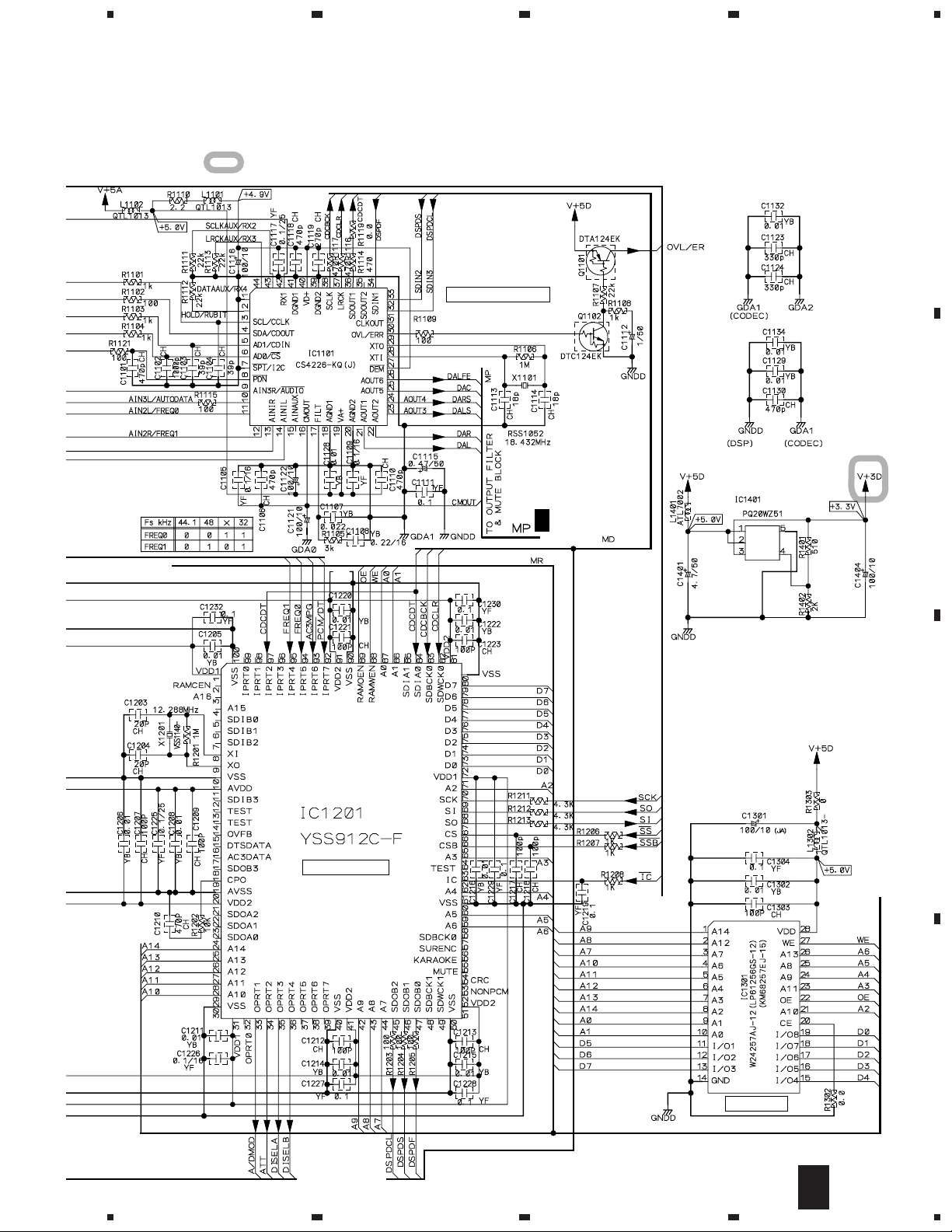
3.3 D.D & INPUT ASSY (1/3)
4
FM/AM TUNER UNIT
A
B
A 1/3
D.D & INPUT ASSY
(XWX3025)
QTL1013
QTL1013
C
VSX-D510
D
12
CN802
1/3
A
1234
E
5
678
VSX-D510
: The power supply is shown with the marked box.
CN303
H
A 3/3
A 2/3
A 3/3
A
CN401
K
B
CN290
F
C
E-VR IC
CN402
K
D
A 2/3
A 3/3
1/3
A
5
6
7
8
13
1
VSX-D510
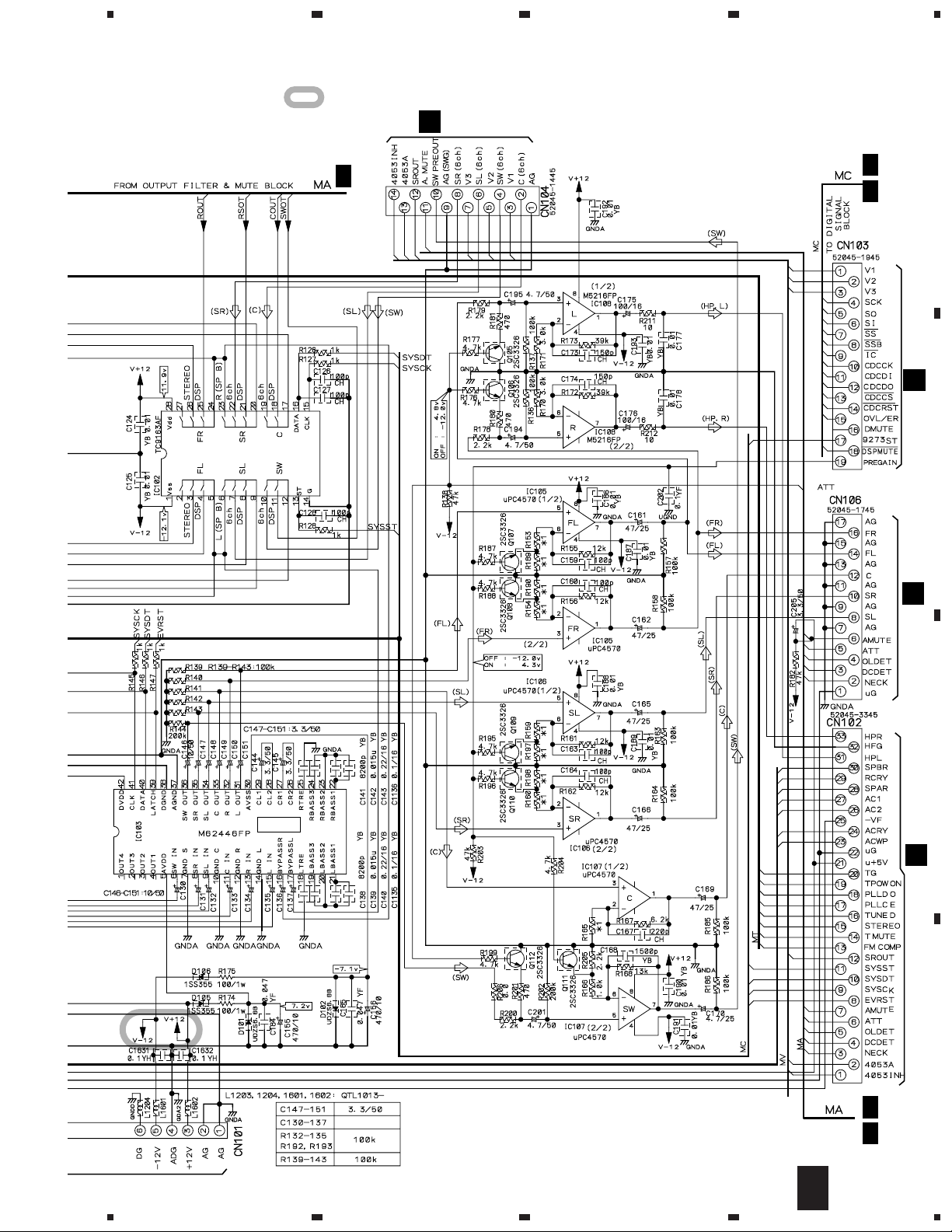
3.4 D.D & INPUT ASSY (2/3)
A
A 1/3
B
23
A 3/3
A
1/3
4
A 2/3
D.D & INPUT ASSY
(XWX3025)
CN1901
J
C
D
14
2/3
A
1234
5
678
VSX-D510
: The power supply is shown with the marked box.
MULTI CH CODEC IC
A 3/3
A
B
C
DTS DECODER IC
D
SRAM(256K)
2/3
A
5
6
7
8
15
1
VSX-D510
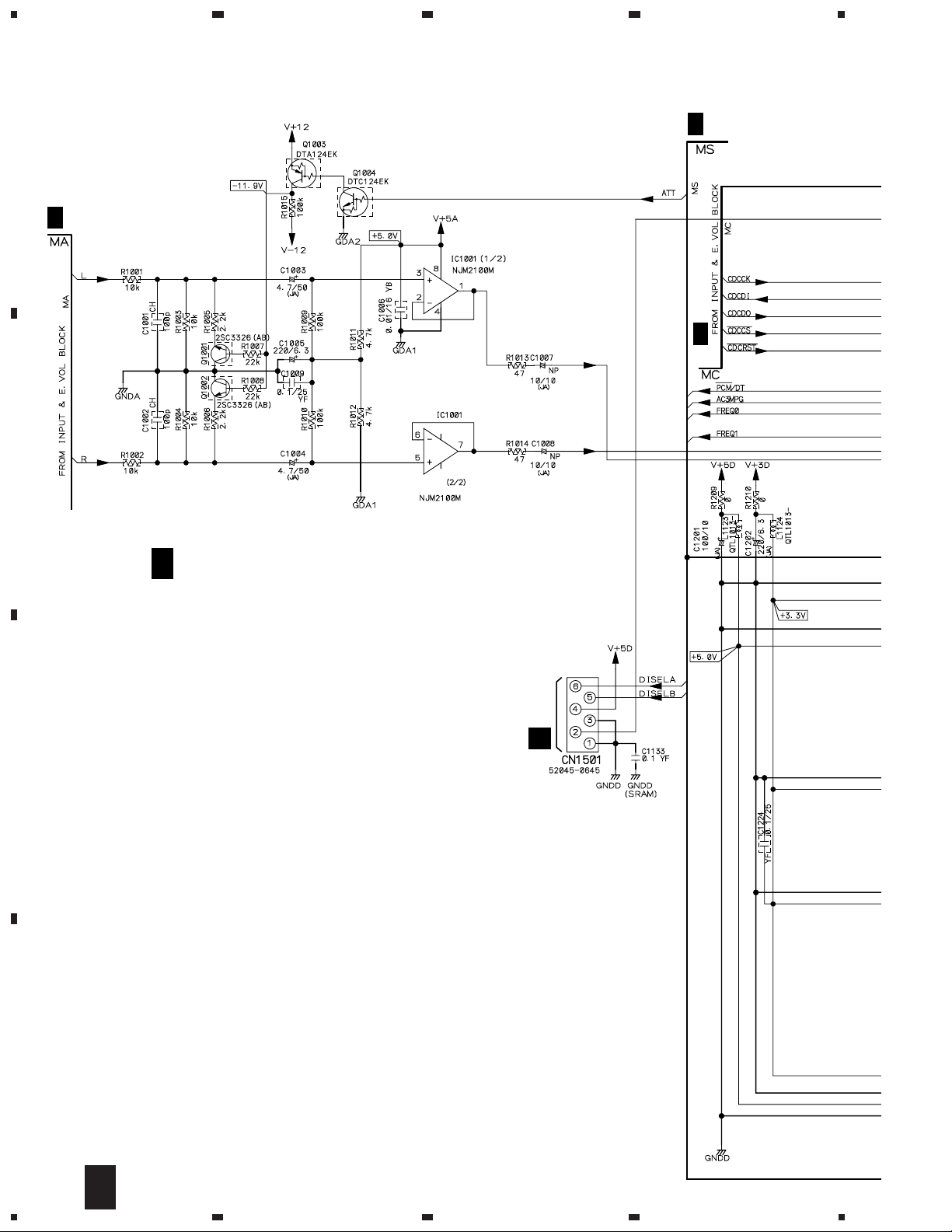
3.5 D.D & INPUT ASSY (3/3)
A 2/3
A
B
23
A 3/3
D.D & INPUT ASSY
(XWX3025)
4
E-SW IC
C
A 2/3
A 1/3
D
16
3/3
A
1234
5
678
VSX-D510
A 1/3
A
B
C
D
3/3
A
5
6
7
8
17
1
23
VSX-D510
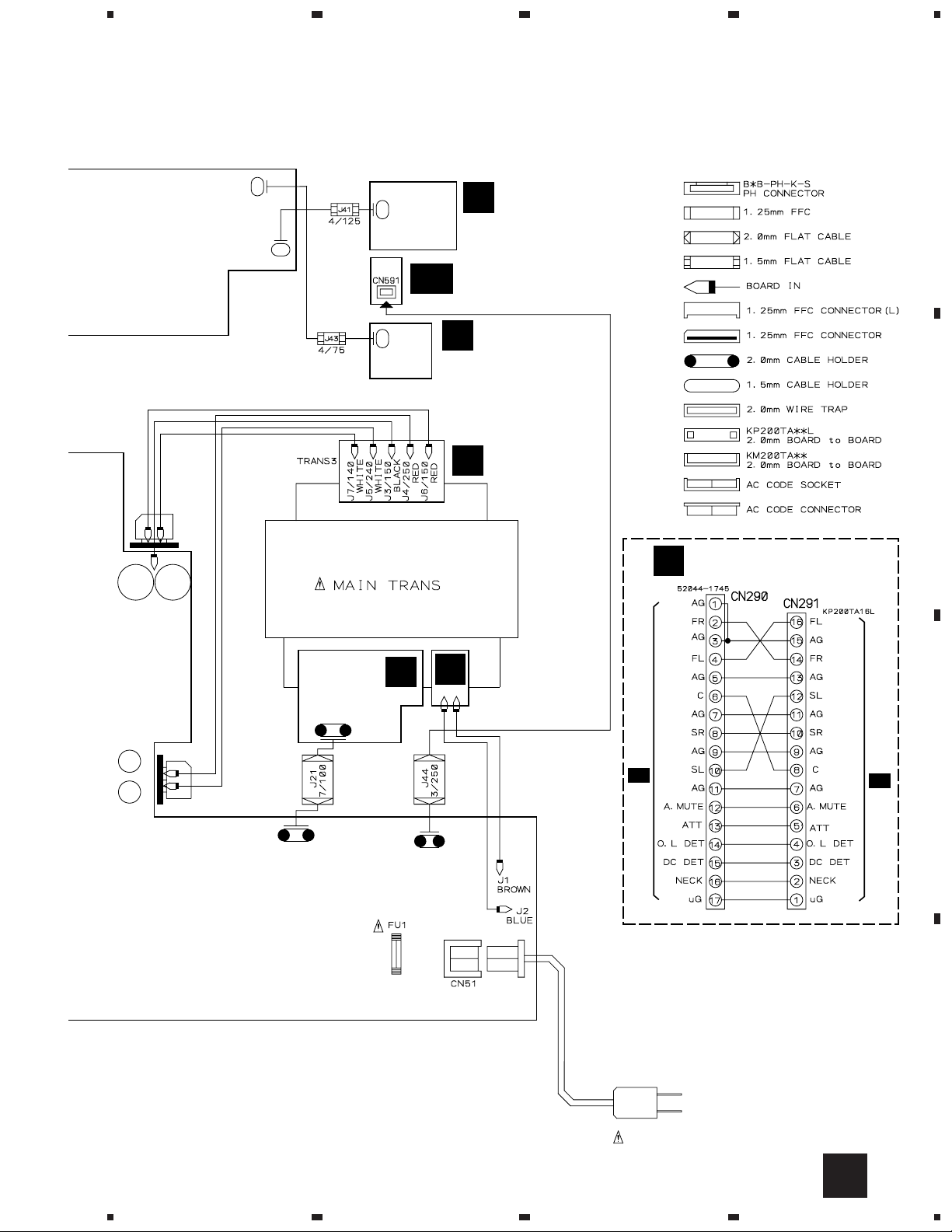
3.6 AMP&PRIMARY (1/2), TRANS2 and TRANS3 ASSYS
4
B 1/2
A
CN291
AMP&PRIMARY ASSY
(XWZ3373)
F
B
C
D
18
1/2
B
1234
 Loading...