

Pioneer VSX-D510 User Manual [en, es]

AUDIO/VIDEO
MULTI-CHAÑNEL RECEIVER
RECEPTOR DE CANALES
MÚLTIPLES DE AUDIO/VÍDEO
^/SÚ-tí5^0
vsx^él 0-G
Operating Instructions
Manuai de instrucciones

WARNING : THE APPARATUS IS NOT WATERPROOFS, TO
PREVENT FIRE OR SHOCK HAZARD, DO NOT EXPOSE THIS
APPLIANCE TO RAIN OR MOISTURE AND DO NOT PUT ANY
WATER SOURCE NEAR THIS APPARATUS, SUCH AS VASE,
FLOWER POT, COSMETICS CONTAINER AND MEDICINE BOTTLE
ETC. HOOIAEn
ADVERTENCIA: EL APARATO NO ES IMPERMEABLE.
NO PONER ALGUNA FUENTE DE AGUA CERCA DEL APARATO,
COMO VASO DE FLORES, RECIPIENTES COSMÉTICOS Y
MEDICINALES, ETC. hooiasp
IMPORTANT
CAUTION
RISK OF ELECTRIC SHOCK
A
The lightning flash with arrowhead symbol, within an
equilateral triangle, is intended to alert the user to the
presence of uninsulated "dangerous voltage" within the
product's enclosure that may be of sufficient magnitude
to constitute a risk of electric shock to persons.
CAUTION:
TO PREVENT THE RISK OF ELECTRIC SHOCK, DO NOT
REMOVE COVER (OR BACK). NO USER-SERVICEABLE
PARTS INSIDE. REFER SERVICING TO QUALIFIED
SERVICE PERSONNEL.
DO NOT OPEN
IMPORTANTE
CAUTION
RISK OF ELECTRIC SHOCK
A
La luz intermitente com el símbolo de punta de flecha
dentro un triángulo equilátero. Está convenido para avisar
el usuario de la presencia de "voltaje peligrosa" no
aislada dentro el producto que podría constituir un peligro
de choque eléctrico para las personas.
ATENCIÓN:
PARA PREVENIR EL PELIGRO DE CHOQUE ELÉCTRICO
NO REMOVER LA TAPA NI LAS PARTES DENTRO NO
UTILIZADAS, LLAMAR UNA PERSONA CUALIFICADA
DO NOT OPEN
Ши : о’ тшшт
° HOOIAChH
CAUTION:
This product satisfies FCC regulations when shielded
cables and connectors are used to connect the unit to
other equipment. To prevent electromagnetic
interference with electric appliances such as radios and
televisions, use shielded cables and connectors for
connections. Hoi2En
' шшшштп > ш > шшш
A
The exclamation point within an equilateral triangle is
intended to alert the user to the presence of important
operating and maintenance (servicing) instructions in the
literature accompanying the appliance. H002_En
A
El punto exclamativo dentro un triángulo equilátero
convenido para avisar el usuàrio de la presencia de
importantes instruciones sobre el funcionamento y la
H002BSP
CAUTION
A
DO NOT OPEN
/^Ш :
А
RISK OF ELECTRIC SHOCK
' шшттшш тш
тш “штш" > °
штшштшп ^ шшшшш'шшм
шш тт тштшт ° ноо2аснн
NOTE: This equipment has been tested and found to comply with the limits for a Class B digital device, pursuant to Part 15 of
the FCC Rules. These limits are designed to provide reasonable protection against harmful interference in a residential
installation. This equipment generates, uses, and can radiate radio frequency energy and, if not installed and used in
accordance with the instructions, may cause harmful interference to radio communications. However, there is no guarantee that
interference will not occur in a particular installation. If this equipment does cause harmful interference to radio or television
reception, which can be determined by turning the equipment off and on, the user is encouraged to try to correct the interference
by one or more of the following measures:
-Reorient or relocate the receiving antenna.
-Increase the separation between the equipment and receiver.
-Connect the equipment into an outlet on a circuit different from that to which the receiver is connected.
-Consult the dealer or an experienced radio/TV technician for help. hoioep
Information to User
Alteration or modifications carried out without appropriate authorization may invalidate the user's right to operate the equipment.
En/Sp/ChH

CAUTION:
THE STANDBY/ON BUTTON IS SECONDARY CONNECTED
AND THEREFORE DOES NOT SEPARATE THE UNIT FROM
MAINS POWER IN STANDBY POSITION. THEREFORE INSTALL
THE UNIT SUITABLE PLACES EASY TO DISCONNECT THE
MAINS PLUG IN CASE OF THE ACCIDENT. THE MAINS PLUG
OFUNITSHOULDBEUNPLUGGEDFROMTHEWALLSOCKET
WHEN LEFT UNUSED FOR A LONG PERIOD OF TIME.
ATENCIÓN:
EL INTERRUPTOR DE ENCENDIDO/EN (STANDBY/ON)
ESPERA ESTÁ CONECTADO EN SECUNDARIO Y POR LO
TANTO NO DESCONECTA AL APARATO DE LA RED CUANDO
ESTE EN LA POSICION DE ESPERA (STANDBY). POR ESO
INSTALE EL APARATO EN LUGARES APROPIADOS FÁCIL DE
DESCONECTAR EL ENCHUFE DE RED EN CASO DE
ACCIDENTE. EL ENCHUFE DE RED DEL APARATO DEBERIA
SER DESCONECTADO DE LA TOMA CUANDO NON VEN
USADO POR UN LARGO PERÍODO DE TIEMPO. hoitbsp
VTS" and VTS Digital Surround" are trademarks of Digital
Theater Systems, Inc. Manufactured under license from Digital
Theater Systems, Inc.
Manufactured under license from Dolby Laboratories. "Dolby", "Pro
Logic" and the double-D symbol are trademarks of Dolby Labora
tories. Confidential Unpublished Works. © 1992-1997 Dolby Labo
ratories, Inc. All rights reserved.
"DTS" y "DTS Digital Surround" son marcas comerciales de
Digital Theater Systems Ine. Fabricado bajo licencia de
Digital Theater Systems Ine.
Fabricado bajo licencia de Dolby Laboratories. "Dolby", "Pro
Logic" y el símbolo con una doble D son marcas comerciales
de Dolby Laboratories. Trabajos confidenciales no publicados.
© 1992 - 1997 Dolby Laboratories. Todos los derechos quedan
reservados.
“DTS”fP“DTS Digital Surround" (DTS
Digital Theater System Inc
$I^^MDigital Theater System Inc ^2:°
° ^ “Dolby” > “pro Logic”
^ ° ©t±
J:W-1^1992-1997£^ o MUm ’ °
TWO VOLTAGE SELECTOR
SWITCHES (multi
voltage model only)
Only multi-voltage model is
provided with these switches.
Mains voltages in Saudi Arabia are
127 V and 220 V only. Never use
this model with the 110 V setting
in Saudi Arabia.
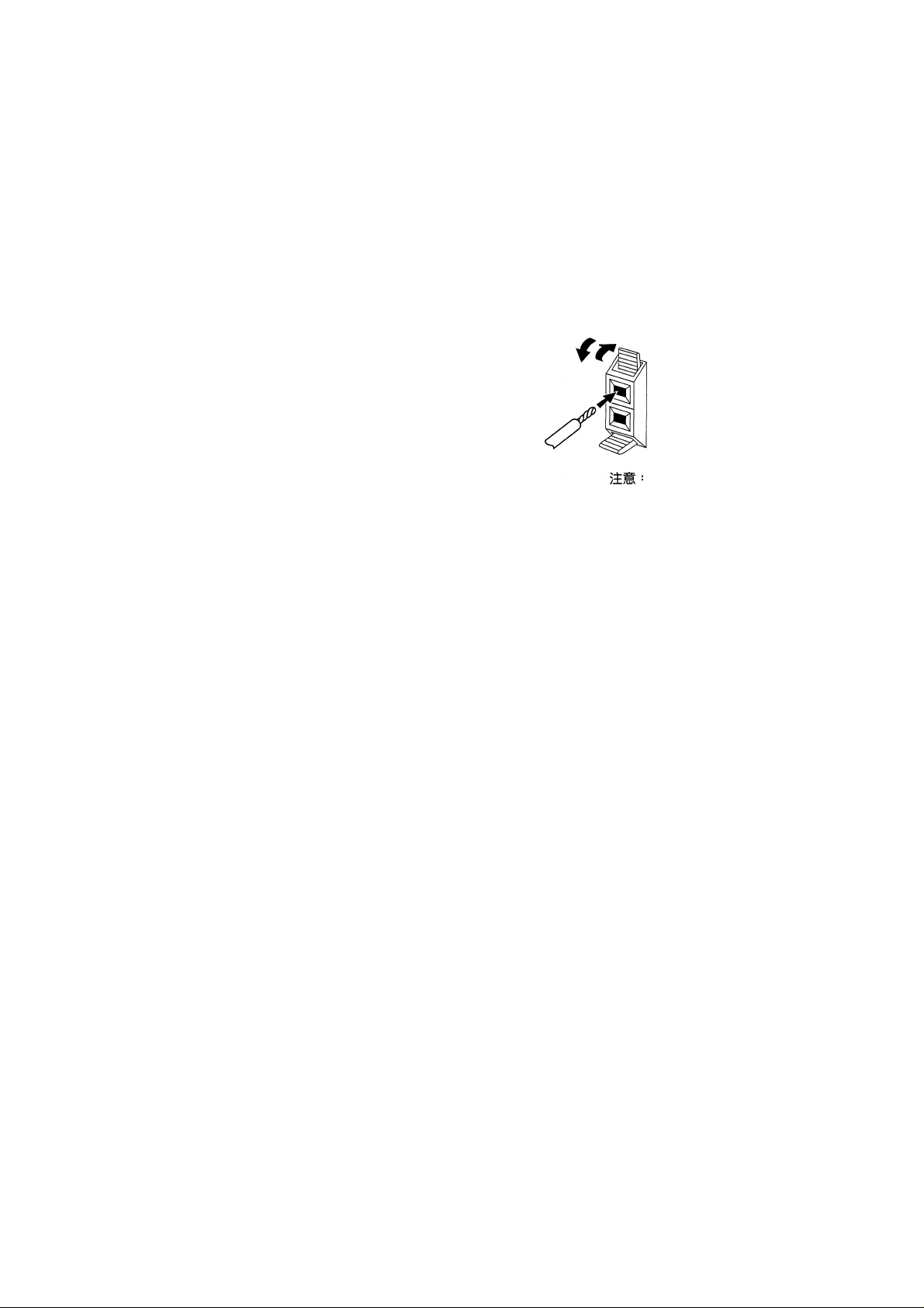
The line voltage selector switches are
on the rear panel. Check that they are
set properly before plugging the
power cord into the household wall
socket. If the voltage is not properly
set or if you move to an area where
the voltage requirements differ, adjust
the selector switches as follows.
1. Use a medium-size screwdriver.
2. First, insert the screwdriver in the
groove of the voltage selector at the
right, and adjust so that the tip of the
groove points to the voltage value of
your area.
3. Next, insert the screwdriver in the
groove of the voltage selector at the
left and adjust until the voltage is the
same as at the right.
DOS CONMUTADORES
SELECTORES DE TENSIÓN
(sólo el modelo
multivoltaje)
La tensión de la red en Arabia
Saudita es de 127 V y 220 V. Nunca
utilice este modelo en Arabia
Saudita con el ajuste para 110 V.
Los conmutadores selectores de la
tensión de línea se encuentran en el
panel trasero. Compruebe que éstos
se encuentren en las posiciones
correctas antes de conectar el cable de
alimentación a una toma de corriente.
Si la tensión está mal ajustada o usted
se desplaza a un área donde los
requerimientos de tensión son
diferentes, ajuste los conmutadores
selectores como se indica a
continuación.
1. Utilice un destornillador de
tamaño medio.
2. Inserte primero el destornillador
en la ranura del selector de tensión de
la derecha y ajústelo de forma que la
punta de la ranura indique hacia el
valor de la tensión utilizada en su
área.
3. A continuación, inserte el
destornillador en la ranura del
selector de tensión de la izquierda y
ajústelo hasta que la tensión sea la
misma que la del selector de tensión
de la derecha.
1Éfl5Í^ail^l27<;^S220f:^ « Sltt.
<■ ;'J>!tSPlÍÍZ
fifi >
B# ’ ÍfgT5lj77ÍÉÜSa}iP#ll ”
2. ’ mmnmmmxiaii
3.
Medium-size screwdriver
Destorniilador de tamaño medio
TWO VOLTAGE SELECTORS
3
En/Sp/ChH

Contents
Congratulations on buying this fine Pioneer product.
Please read through these operating instructions so you will know how to operate your model properly After you have
finished reading the instructions, put them away in a safe place for future reference.
01 Contents 4 07 02 Introductory Information 7
Checking the Supplied Accessories 7
Using this Manual 7
Installing the Receiver 7
Loading the Batteries 8
Operating Range of Remote Control Unit 8 08
When Making Cable Connections 8
03 Connecting Your Equipment 9
Connecting Digital Components 10 09
Connecting Audio Components 11
Connecting DVD 5.1 Channel Components 12
Connecting Video Components 13
Connecting Antennas 14
Using External Antennas 15
Connecting Speakers 16
Hints on speaker placement 17
Operating Other Pioneer Components 19
04 Preparations 20
Setting Up for Surround Sound 20
Setting the Volume Level of Each Channel 30
Using the Tuner 47
Finding a Station 47
Channel Step Setting 48
Tuning Directly to a Station 49
Memorizing Stations 50
Recalling Memorized Stations 51
Making a Recording 52
Making an Audio or a Video Recording 52
Record MONITOR 53
Controlling the Rest of Your System 53
Setting Up the Remote Control 53
Clearing All the Remote Control Settings 56
Direct Function (MULTI CONTROL) 57
CD/MD/CD-RWCR/DVD/LD/DVR Player/
Cassette Deck Controls 58
Cable TV/Satellite TV/TV/DTV Controls
Preset Code List 64
Additional Information
Troubleshooting 65
Specifications 68
65
59
05 Displays & Controls 31
Front Panel 31
Display 34
Remote Control 36
06 Sound Modes 40
Learning about the Sound Modes 40
Switching ANALOG/DIGITAL Signal Input 42
Playing Sources with Dolby Digital or DTS Sound
43
Selecting a Sound Mode 44
MIDNIGHT Listening Mode 45
ADVANCED THEATER Mode ( Dolby/DTS mode)
45
Playing Other Sources 46
4
En

Indice
Enhorabuena por su adquisición de este excelente producto Pioneer.
Para saber cómo utilizar correctamente su modelo lea detenidamente este manual de instrucciones. Después de haber
finalizado su lectura, guárdelo en un lugar seguro para futuras referencias.
Utilización del sintonizador 47
01 Indice 5 02 Información de introducción 7
Confirmación de los accesorios incluidos 7
Uso de este manual 7
Instalación del receptor 7
Inserción de las pilas 8
Alcance del mando a distancia 8
Cuando haga las conexiones de cable 8
03 Conexión de su equipo 9
Conexión de componentes digitales 10
Equipos de audio 11
Conexión de componentes DVD de 5,1 canales 12
Equipos de video 13
Conexión de las antenas 14
Utilización de antenas externas 15
Conexión de altavoces 16
Consejos para la instalación de los altavoces 17
Euncionamiento de otros equipos de Pioneer 19
04 Preparativos 20
Ajustes para sonido ambiental 20
Ajuste del nivel de volumen de cada canal 30
05 Indicaciones y controles 31
Panel delantero 31
Indicaciones 34
Mando a distancia 36
07
Búsqueda de una emisora 47
Ajuste de intervalo entre canales 48
Sintonización directa de una emisora 49
Memorización de emisora 50
Llamado de emisoras memorizadas 51
Para hacer una grabación 52
08
Para hacer una grabación de audio o video 52
MONITOR de grabación 53
Control del resto de su sistema 53
09
Ajuste del mando a distancia 53
Borrado de todos los ajustes del mando a
distancia 56
Punción directa (MULTI CONTROL) 57
Controles del tocadiscos de discos compactos/
minidiscos/CD-R/videograbadora/DVD/discos láser/
reproductor de DVR/platina de casetes 60
Controles de TV cable/TV satélite/TV/DTV 61
Lista de códigos prefijados 64
Información adicional
10
Loclaización de averías 65
Especificaciones 69
65
06 Modos de sonido 40
Aprendizaje de los modos de sonido 40
Cambio de entrada de señal analógica/digital 42
Reproducción de fuentes con sonido Dolby Digital o
DTS 43
Selección de un modo de sonido 44
Utilización en el modo de escucha de
medianoche 45
Modo de cine de avanzada
(modo Dolby/DTS) 45
Reproducción de otras fuentes 46
5
Sp

шяф{йй!1й0ч* ’
ттмшшщшшшшш
»
шшштшш
•
шштш
>
01 аш 6
02
mmmi^
шшш
ШАШШ
^е§1йШ№«5и
03
BXïBjæi 9
Ш#ШД# Il
jlfgDVDS.l^ìiìfflft
ашшм# 13
шшштш 16
тшшшшшшш
04 íliHf
07 47
Я5ва 47
7
8
10
12
CHANNEL STEP SETTING (ЩЛ
шшттт
50
ÜtHiBtlWf
08
09
^ 52
шпштшшшш
«WSêilJfg 53
ЙЙ1§1ЙВ 53
»PÂiieti±È^mwfSB 56
49
51
52
ÎsSIÈ)
53
48
ШШР]Ш 57
14
15
17
19
20
20
30
CD / MD / CD-R / VCR / DVD / LD / DVRfflftfi /
ЩШШт 62
Ш йШ Ш / Ш Ш / Ш Ш / DTvgfiJ 63
asÆf-tes» 64
10
шштш
65
65
70
05
06 mmmiz
6
ChH
31
1ЕШ® 31
ШжИ 34
36
40
40
ANALOG/DIGITAL {ШШ/Ш^)
ÄiÄIIA 42
44
MIDNIGHT (4^íí|Í) tlÄ 45
(Dolby/DTSflÿÇ) 45
ШШЖШШШ 46
тшштю т
43

Introductory
Information
Checking the Supplied Accessories
Please check that you've received the
following supplied accessories:
• AM loop antenna
• FM wire antenna
• Dry cell batteries (AA size lEC
R6P) X 2
• Remote control
• Operating instructions
Using this Manual
This manual is for the VSX-D510/
VSX-D510-G audio/video multi
channel receivers.
It is divided into two main sections:
Set up
This section covers installing your
receiver and connecting up all the
other components in your home
theater system to it. It also describes
how to set up a multi-channel
speaker system to take full advantage
of the great surround sound features
of your receiver.
Operation
This section shows you how to use
every feature of the receiver and its
remote control unit. It also covers
using the supplied remote control to
operate your other home theater
components. To find out more about
a specific button, control or indicator,
see Displays & Controls starting on
page 31. This will point you to the
relevant chapter in the manual.
In the Additional Information section
(p.65-68) you'll find a troubleshoot
ing section and specifications.
Installing the Receiver
Ventilation
• When installing this unit, make
sure to leave space around the unit
for ventilation to improve heat
radiation (at least 60 cm at the top,
10 cm at the rear, and 30 cm at each
side). If not enough space is provided
between the unit and walls or other
equipment, heat will build up inside,
interfering with performance or
causing malfunctions.
• Do not place on a thick carpet,
bed, sofa or fabric having a thick pile.
Do not cover with fabric or other
covering. Anything that blocks
ventilation will cause the internal
temperature to rise, which may lead
to breakdown or fire hazard.
Información de introducción
Confirmación de los
accesorios incluidos
Confirme que se han recibido los
siguientes accesorios incluidos:
• Antena de cuadro de AM
• Antena de cable de FM
• Pilas (R6P lEC de tamaño AA) x 2
• Mando a distancia
• Manual de instrucciones
Uso de este manual
Este manual fue escrito para los
sintoamplificadores multicanales de
audio/video VSX-D510/VSX-D510-C.
Está dividido en dos secciones
principales:
Instalación
Esta sección muestra la instalación de
su sintoamplificador y la conexión de
todos los demás equipos de sus sistema
de cine en el hogar. También describe
cómo instalar un sistema de altavoces
multicanal para aprovechar todas las
ventajas de sus importantes funciones
de sonido ambiental de su
sintoamplificador.
Funcionamiento
Esta sección muestra cómo utilizar todas
las funciones de su sintoamplificador y
su mando a distancia. También describe
el uso del mando a distancia incluido
para hacer funcionar sus otros equipos
de cine en el hogar. Para buscar
información detallada sobre un botón,
control o indicador específico, consulte
las Indicaciones y Controles a partir de la
página 31. Encontrará referencias al
capítulo correspondiente de este manual.
La sección de Información adicional
(página 65-69) incluye una sección de
localización de averías y las
especificaciones.
Instalación del receptor
Ventilación
• Cuando instale esta unidad,
asegúrese de dejar suficiente espacio
alrededor de la unidad como para que
circule el aire y se disperse el calor (por
lo menos 60 cm arriba, 10 cm detrás,
30 cm en cada lado). Si no hay
suficiente espacio entre la unidad y las
paredes u otros equipos, el calor se
acumulará en el interior, interfiriendo
con el funcionamiento y provocando
averías.
• No coloque sobre una alfombra
mullida, sofá o tela de hebras largas. No
cubra con tela u otra cubierta.
Si se tapan las salidas de aire,
aumentará la temperatura en el interior
y puede romperse o provocar un
incendio.
<3
mmmv^
(AARTf-/IEC R6P)x2
• mimmt
í Í®fW#ÍÍÍVSX-D510/VSX-D510-G
mm
» íe “Sííjait-m
(H65-70H).
(iisr
> Í^ÜjlOcm ’
30cm) ■>
Pi “
• «««№ Wteíi± ' '
»mm
mmmmM'smmma ° pim
7
En/Sp/ChH

Dry cell batteries (AA size lEC R6P) x 2
Loading the batteries Inserción de las pilas
CAUTION:
Incorrect use of batteries may result
in such hazards as leakage and
bursting. Observe the following
precautions:
• Never use new and old batteries
together.
• Insert the plus and minus sides of
the batteries properly according to
the marks in the battery case.
• Batteries with the same shape may
have different voltages. Do not use
different batteries together.
• When disposing of used batteries,
please comply with governmental
regulations or environmental public
instruction’s rules that apply in your
country or area.
¡PRECAUCION!
El uso incorrecto de las pilas puede
provocar situaciones peligrosas tales
como fugas o explosión. Tenga en
cuenta las siguientes precauciones:
• No utilice nunca pilas nuevas y
viejas al mismo tiempo.
• Inserte correctamente los lados
positivo y negativo de las pilas de
acuerdo con las marcas en la caja de
pilas.
• Hay pilas que tienen la misma
forma pero con distintos voltajes. No
utilice pilas diferentes al mismo tiempo.
• Cuando tiene que desembarazarte
de las baterías usadas, por favor se
adapte a los reglamentos govemamentales o a las desposiciones en materia
ambiental en vigor en su país o área.
Operating Range of Remote Control Unit
The remote control may not work
properly if;
® There are obstacles between the
remote control and the receiver's
remote sensor.
• Direct sunlight or fluorescent light
is shining onto the remote sensor.
• The receiver is located near a
device that is emitting infrared rays.
• The receiver is operated simulta
neously with another infrared remote
control unit.
When Making Cable Connections
Be careful not to arrange cables in a
manner that bends the cables over
the top of this unit as shown in the
illustration. If the cables are brought
over this unit, the magnetic field
produced by the transformers in this
unit may cause a humming noise to
8 come from the speakers.
En/Sp/ChH
Alcance del mando a distancia
El mando a distancia no funcionará
correctamente cuando:
• Hay obstáculos entre el mando a
distancia y el sensor a distancia del
sintoamplificador.
• Los rayos del sol o la luz
fluorescente se reflejan directamente
en el sensor a distancia.
• El sintoamplificador está instalado
cerca de un aparato caliente que está
emitiendo rayos infrarrojos.
• El sintoamplificador se utiliza
simultáneamente con otro mando a
distancia por infrarrojos.
Cuando haga las conexiones de cable
No coloque los cables de tal forma que
se curven sobre este aparato, como en la
figura. Si los cables se dejan encima de
este aparato, el campo electromagnético
producido por los transformadores en el
aparato puede hacer que se escuchen
zumbidos por los altavoces.
“ + ” tifJJíP ” ti
fi»
• > «Er-sts
^ »
tiiij »
Pf»»
±»
lií »
«»
’ mi ’ tai^i
Connecting Your
Equipment
Conexión de su
equipo
d
Before making or changing the
connections, switch off the power
and disconnect the power cord
from the AC outlet.
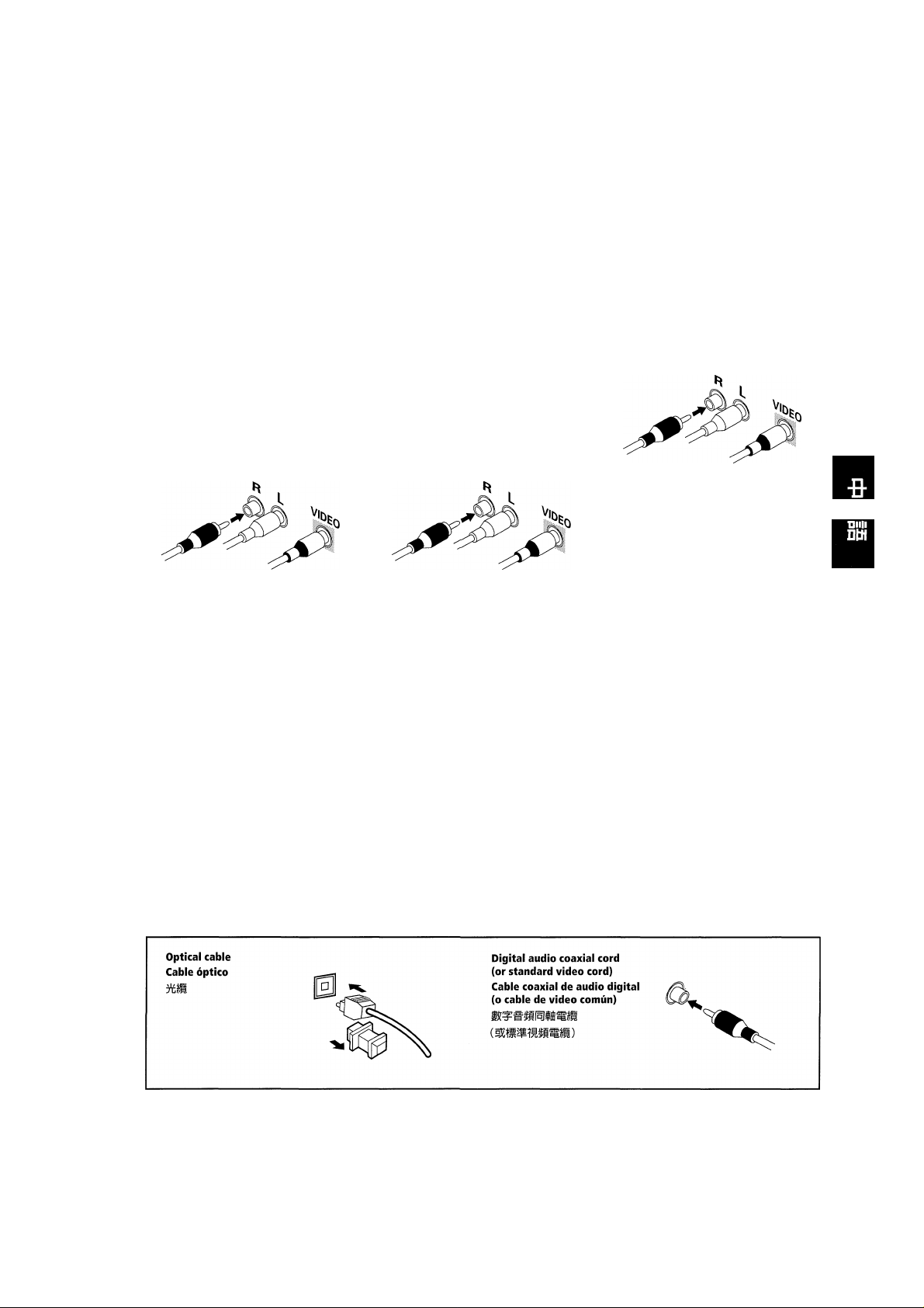
Audio/Video Cords
Use audioMdeo cords (not supplied)
to connect the video components and
a video cord to connect the monitor
TV
Connect red plugs to R (right), white
plugs to L (left), and the yellow plugs
to VIDEO.
Be sure to insert completely.
Digital Audio Cords/Optical
Cables
Commercially available digital audio
coaxial cords (standard video cords
can also be used) or optical cables
(not supplied) are used to connect
digital components to this receiver.
When you use optical digital input or
output terminals, pull off the caps
and insert the plugs. Be sure to insert
completely.
Antes de hacer o cambiar las
conexiones, desconecte el
interruptor y desenchufe el cable
eléctrico del tomacorriente.
Cables de audio/video
Utilice los cables de entrada de audio/
video suministrados para conectar los
equipos de video y un cable de video,
para conectar el monitor de TV
Conecte las clavijas rojas en R
(derecha), las clavijas blancas en L
(izquierda) y las clavijas amarillas en
VIDEO.
Inserte completamente.
Cables de audio digital/ cables ópticos
Hay cables coaxiales de audio digital
de venta en los comercios (también
pueden utilizarse cables de video
comunes) o cables ópticos (no
suministrados) para conectar los
equipos digitales a este
sintoamplificador.
Cuando utilice terminales de entrada
o salida digital óptica, retire las tapas
e inserte los enchufes. Inserte
completamente.
r (*) ± ’
glíSiiJ L ( & ) ± ’ Äfeif
VIDEO± “ A °
«a
(mímmmwMmm
m
(Aia««)
üf gfuT >
wmmmmx
°
En/Sp/ChH
9
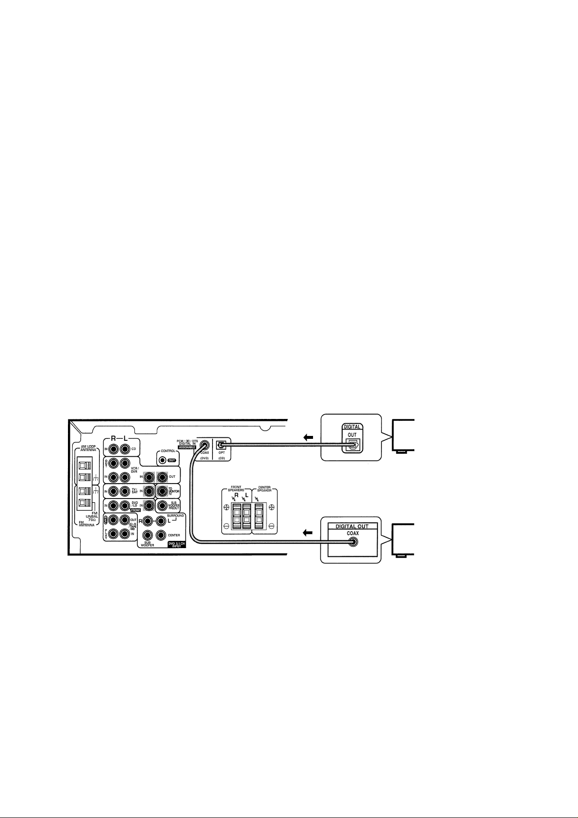
Connecting Digital
Components
In order to use PCM/DD Digital/
DTS soundtracks, you need to
make digital audio connections. You
can do this by either coaxial or optical
connections (you do not need to do
both). The quality of these two types
of connections is the same but since
some digital components only have
one type of digital terminal, it is a
matter of matching like with like (for
example, the coaxial out from the
component to coaxial in on the
receiver). The VSX-D510/VSX-D510G has a coaxial and an optical input
for a total of two digital inputs.
Connect your digital components as
shown below.
When connecting your equipment,
always make sure the power is turned
off and the power cord is discon
nected from the wall outlet.
Conexión de componentes digitales
Para escuchar las pistas de sonido
PCM/DD Digital/DTS, es necesario
hacer conexiones de audio digital.
Puede hacerlo con conexiones
coaxiales u ópticas (no necesita hacer
ambas). La calidad de estos dos tipos
de conexiones es la misma pero como
algunos componentes digitales sólo
tienen un tipo de terminal digital,
seleccione el correspondiente a su
equipo (por ejemplo, la salida coaxial
del componente a la entrada coaxial
del sintoamplificador). Conecte sus
equipos digitales como se indica a
continuación. Hay una toma de salida
digital (sólo para VSX-D510/VSXD510-G). Al conectar su equipo
asegúrese siempre de que la
alimentación está apagada y de que el
cable de alimentación está
desenchufado del tomacorriente.
/üam
?:/DTS igí
iHiiira (í?ijíp
°vsx-
D510/VSX-D510-GM^-*f g |W1
^mxim °
rnrnimihmmmmyjñ °
The arrows indicate the direction of the
audio signal.
Las flechas indican el sentido de la señal
de audio.
DVD player
Tocadiscos
de DVD
üMdmm
CD player
Tocadiscos
de discos
compactos
□
□
10
En/Sp/ChH
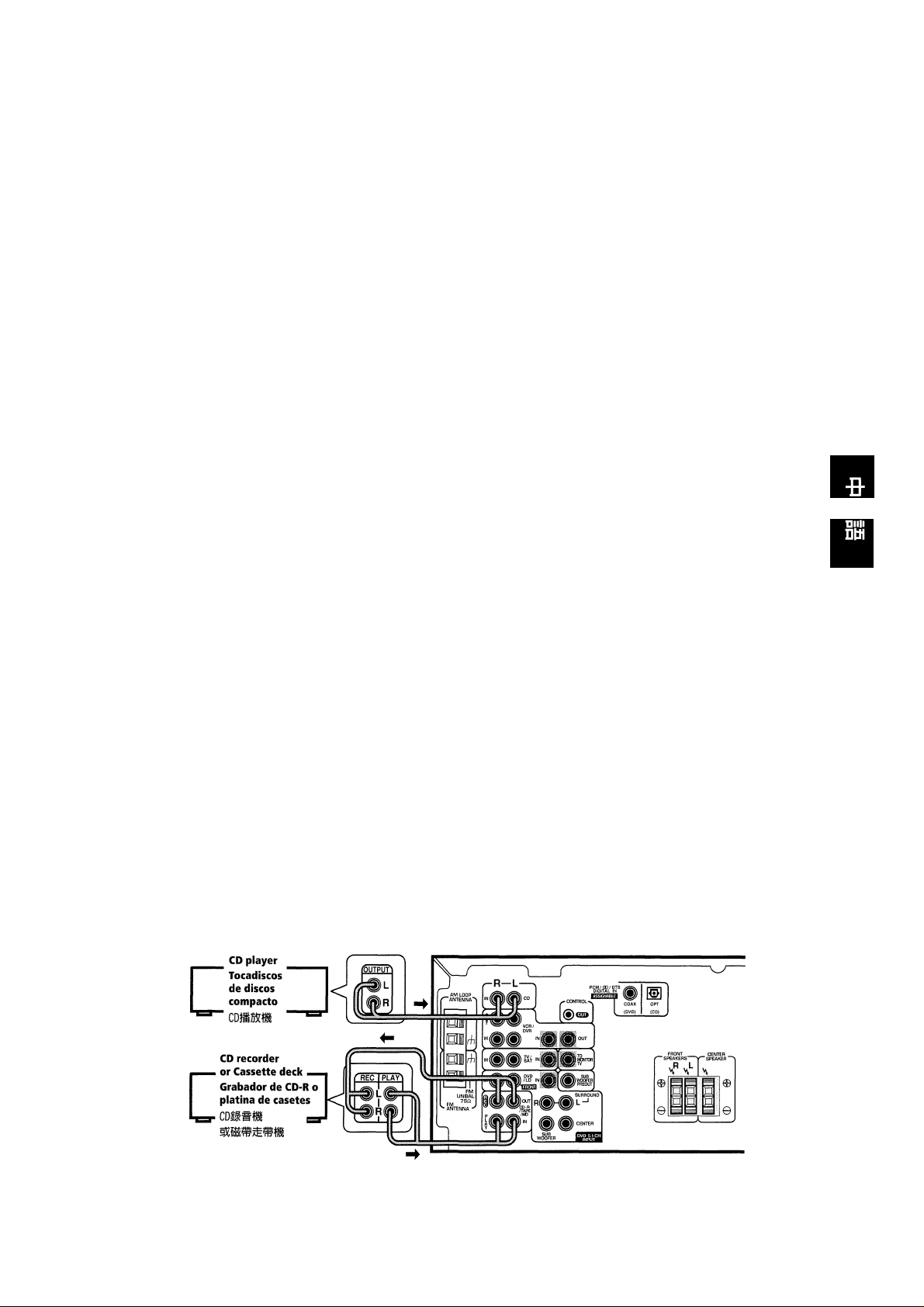
Connecting Audio
Components
To begin set up, connect your audio
components to the jacks as shown
below. These are all analog connec
tions and your analog audio compo
nents (like a cassette deck) use these
jacks. Remember that for components
you want to record with, you need to
hook up four plugs (a set of stereo ins
and a set of stereo outs), but for
components that only play, you only
need to hook up one set of stereo
plugs (two plugs). To use Digital
source features you must hook up
your digital components to the digital
inputs but it is also a good idea to
hook up your digital components to
analog audio jacks. If you want to
record to/from digital components
(like an MD) to/from analog compo
nents, you must hook up your digital
equipment with these analog
connections. See page 10 for more on
digital connections.
When connecting your equipment,
always make sure the power is turned
off and the power cord is discon
nected from the wall outlet.
Cassette deck placement
Depending on where the cassette
deck is placed, noise may occur
during playback of your cassette deck
which is caused by leakage flux from
the transformer in the receiver. If you
experience noise, move the cassette
deck farther away from the receiver.
The arrows indicate the direction of the
audio signal.
Equipos de audio
Empiece la instalación conectando sus
equipos de audio a las tomas tal como
se indica a continuación. Todas estas
conexiones son analógicas y sus
equipos de audio analógicos (platina
de casetes, etc) utilizan estas tomas.
Tenga en cuenta que los equipos con
los que desea grabar deben conectarse
las cuatro clavijas (un juego de clavijas
de entrada estéreo y un juego de
clavijas de salida estéreo), pero para los
equipos que sólo se utilizan para
reproducir, sólo es necesario conectar
un juego de clavijas estéreo (dos
clavijas). Para utilizar las funciones de
fuentes digitales debe conectar sus
equipos digitales en las entradas
digitales pero también es conveniente
conectar sus equipos digitales a las
tomas de audio analógico. Si desea
grabar de/a un equipo digital (como un
minidisco) a/de un equipo analógico,
debe conectar su equipo digital con
estas conexiones analógicas. Consulte
la página 10 para más detalles sobre las
conexiones digitales.
Al conectar su equipo asegúrese
siempre de que la alimentación está
apagada y de que el cable de
alimentación está desenchufado del
tomacorriente.
Instalación de la platina de casetes
Según el lugar donde se coloca la
platina de casetes, puede escucharse
ruido durante la reproducción de su
platina de casetes, debido a las fugas
eléctricas del transformador en el
sintoamplificador. Si se escuchan
ruidos, aleje la platina de casetes del
sintoamplificador.
’ íSTiim^ ’
#iiígíij«n± °
«) íífflaífcfip o tTjia ’
m
4
lAÍSsl
íüíisi) ’í№
m) »
mmmmmmmnmm p
ft (®MD) ±íi#.
ft (№d) ±fttIMft±»# - gt
IgioH»
-lA“
ISSI}Í5^víiJ«iHÍ5É750»
rntsm
(-*
{2mm
±»> m
C2
> fl»
Las flechas indican el sentido de la señal
de audio.
11
En/Sp/ChH
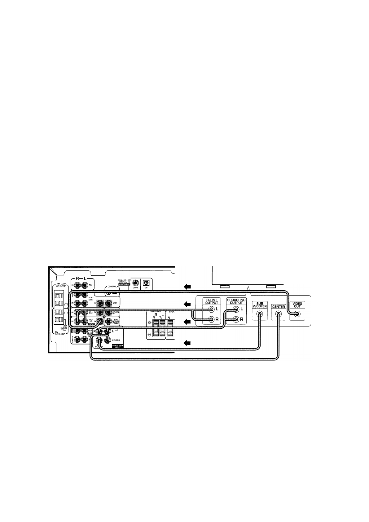
Connecting DVD 5.1
Channel Components
DVD and LD discs are compatible
with both 2 channel and 5.1 channel
audio output formats. Connections
can be made from a DVD, multi
channel decoder equipped with 5.1
analog outputs to the 5.1 analog
inputs on this unit. Always make sure
that the receiver is switched off and
unplugged from the wall outlet before
making or changing any connections.
MEMO:
• The 5.1 channel input can only be
used when DVD 5.1 CH is selected.
Conexión de componentes DVD de 5,1 canales
Los discos láser y discos DVD son
compatibles con formatos de salida de
audio tanto de 2 canales como de 5,1
canales. Las conexiones pueden
hacerse desde un decodificador
multicanal/DVD equipado con salidas
analógicas 5,1 a las entradas
analógicas 5,1 de este aparato.
Asegúrese siempre de que el
sintoamplificador está desconectado y
desenchufado del tomacorriente antes
de realizar o cambiar las conexiones.
MEMO:
• La entrada de 5,1 canales sólo
puede utilizarse cuando se ha
seleccionado DVD 5,1 CH.
MgDVD5.1^5imff
DVDSffiLDggfffl 2
§ o ñJUÍIfSEW5.ltI}SfÍIttilfiP№VD
. i
iiíSfiAfflp»
m ’ míi!iSE«±ispffiíii»
MEMO:
• RWílíÍ7DVD5.1CH7f-#gffiffl5.1
DVD/multi channel
decoder with 5.1 channel
analog output jacks
Decodificador
multicanal/DVD con
tomas de salida
analógicas de 5,1 canales
DVD/Píií5.1^iÍIÍMthíÍ
12
En/Sp/ChH
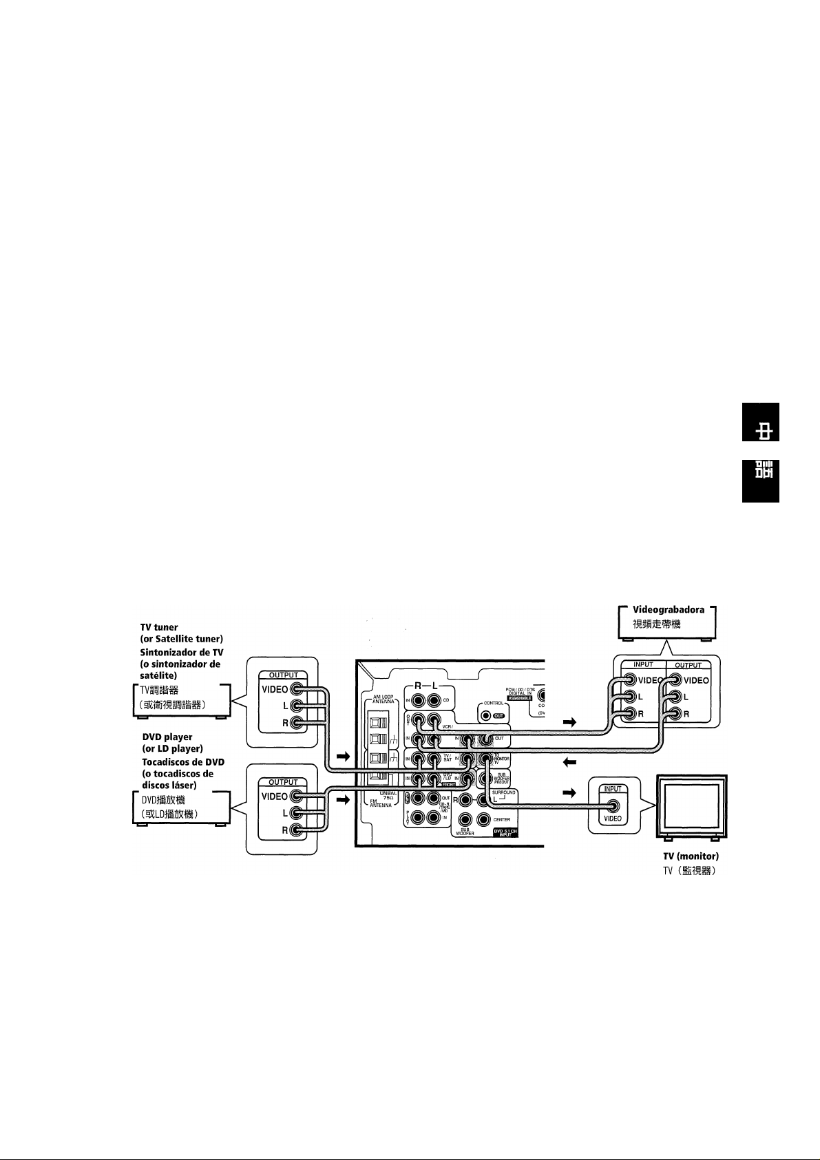
Connecting Video
Components
Connect your video components to
the jacks as shown below. Regarding
digital video components (like a DVD
player), you must use the analog
connections pictured on this page for
the video signal but in order to hear a
digital source (like a DVD) you
should hook up their audio to a
digital input (see page 10). It is also a
good idea to hook up your digital
components with analog audio
connections as well (see page 11).
When connecting your equipment,
always make sure the power is turned
off and the power cord is discon
nected from the wall outlet.
Equipos de video
Conecte sus equipos de video en las
tomas, tal como en la figura a
continuación. Con respecto a los
equipos de video (como un
tocadiscos de DVD) se deben utilizar
las conexiones analógicas de esta
página para la señal de video pero
para utilizar una fuente digital debe
conectar su audio a una entrada
digital (consulte la página 10). Es
conveniente conectar sus equipos
digitales también con conexiones de
audio analógicas (consulte la página
11).
Al conectar su equipo asegúrese
siempre de que la alimentación está
apagada y de que el cable de
alimentación está desenchufado del
tomacorriente.
C!
v d mm
li) ’ mBnmfím ’ wmimt-
(№vDfS&íi) -stllllf*
3 ’ “'äEI
í«B«±lfiPíftty»
VCR
13
En/Sp/ChH
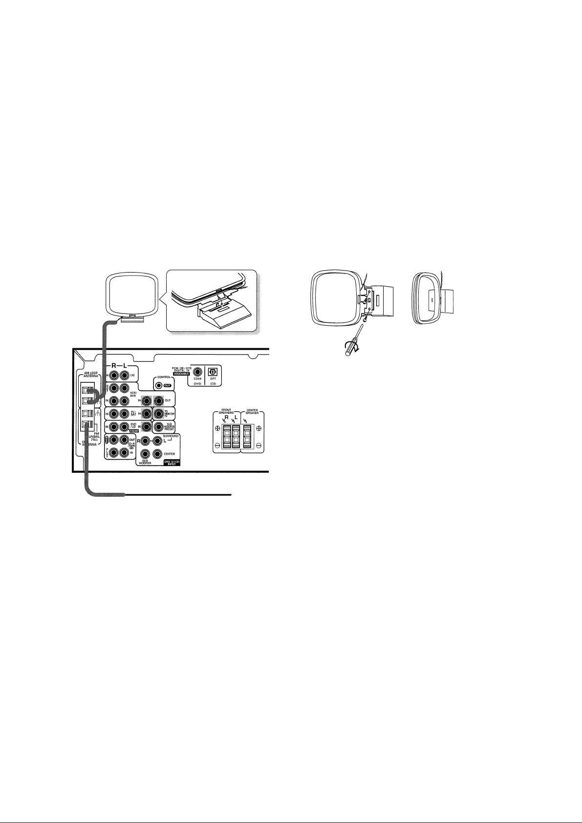
Connecting Antennas Conexión de las antenas
Connect the AM loop antenna and
the FM wire antenna as shown below
To improve reception and sound
quality, connect external antennas
(see Using external antennas, below).
Always make sure that the receiver is
switched off and unplugged from the
wall outlet before making or changing
any connections.
Conecte la antena de cuadro de AM y
la antena de cable de FM tal como se
indica a continuación. Para mejorar la
recepción y la calidad del sonido,
conecte antenas externas (consulte
Utilización de antenas externas mas
adelante). Asegúrese siempre de que
el sintoamplificador está apagado y
desenchufado del tomacorriente antes
de realizar o cambiar las conexiones.
AM loop antenna
Assemble the antenna and connect to the receiver.
Attach to a wall, etc. (if desired) and face in the
direction that gives the best reception.
féTiim/F: ’ mimmmMmmm
(MTX
ir ) ° ’
FM wire antenna
Connect the FM wire antenna and fully extend
vertically along a window frame or other suitable
area, etc.
Antena de cable de FM
Conecte la antena de cable de FM y extienda
verticalmente a lo largo del marco de una ventana
o de otra área adecuada.
rnm&w »
Antena de cuadro de AM
Arme la antena y conéctela al sintoamplificador.
Instale en una pared, etc. (si lo desea) y apunte en
el sentido en el que la recepción sea la mejor
posible.
0^77 |é] <=
14
En/Sp/ChH
Antenna snap connectors
Twist the exposed wire strands
together and insert into the hole, then
snap the connector shut.
Conectores de antena de resorte
Retuerza los hilos de cable expuestos
entre sí e inserte en el orificio,
soltando el conector para cerrar el
orificio.
10 mm
G
i’
isítaaii
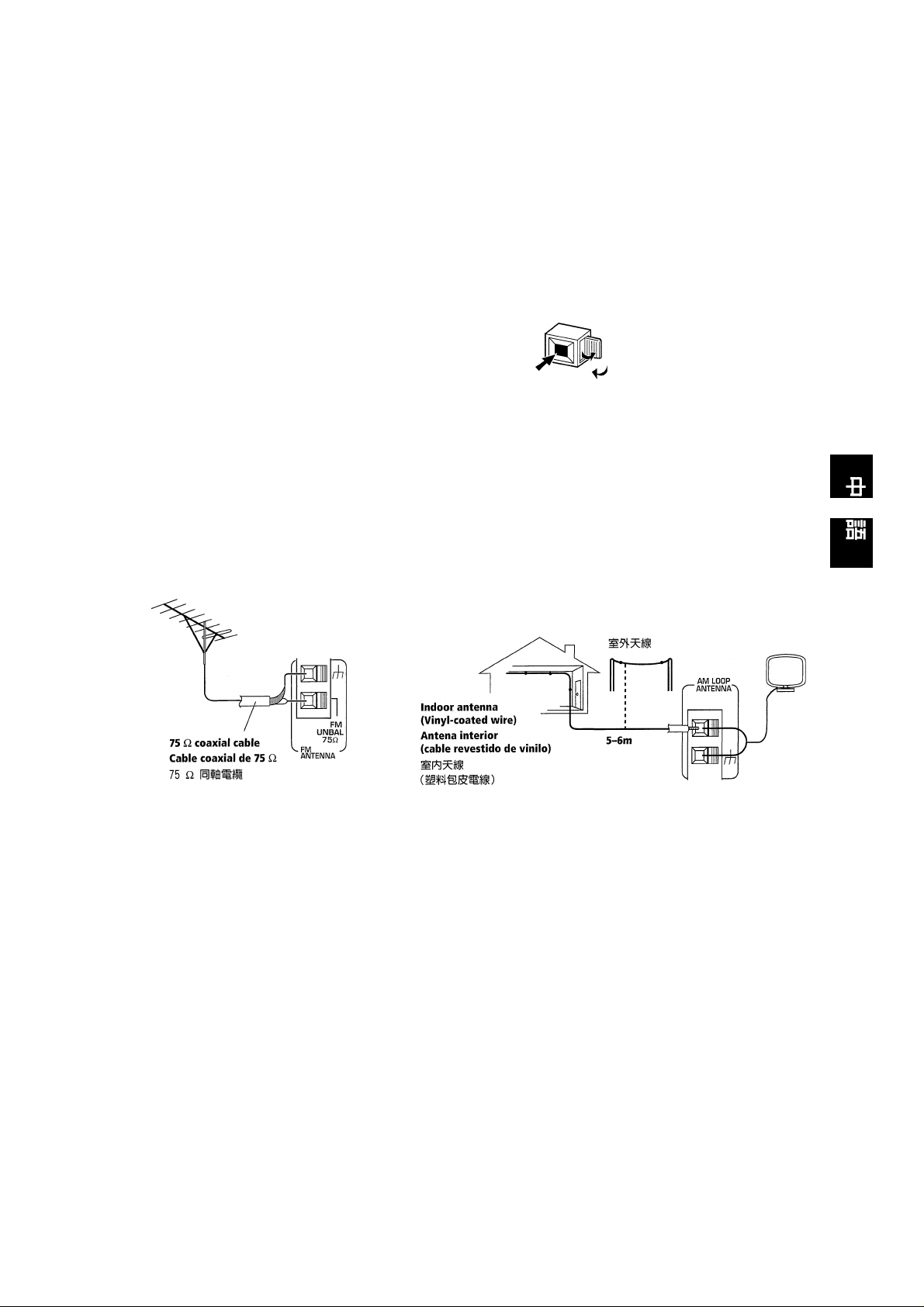
Using External Antennas
To improve FM reception
Connect an external FM antenna.
To improve AM reception
Connect a 5-6 m length of vinylcoated wire to the AM antenna
terminal without disconnecting the
supplied AM loop antenna.
For the best possible reception,
suspend horizontally outdoors.
Utilización de antenas externas
Para mejorar la recepción de FM
Conecte una antena de FM exterior.
Para mejorar la recepción de AM
Conecte un cable revestido de vinilo
de 5-6 metros en el terminal de
antena de AM sin desconectar la
antena de cuadro de AM
suministrada.
Para una recepción óptima, cuelgue
horizontalmente en exteriores.
Outdoor antenna
Antena exterior
r5íT ’
7KzpüliffiS^1- »
15
En/Sp/ChH
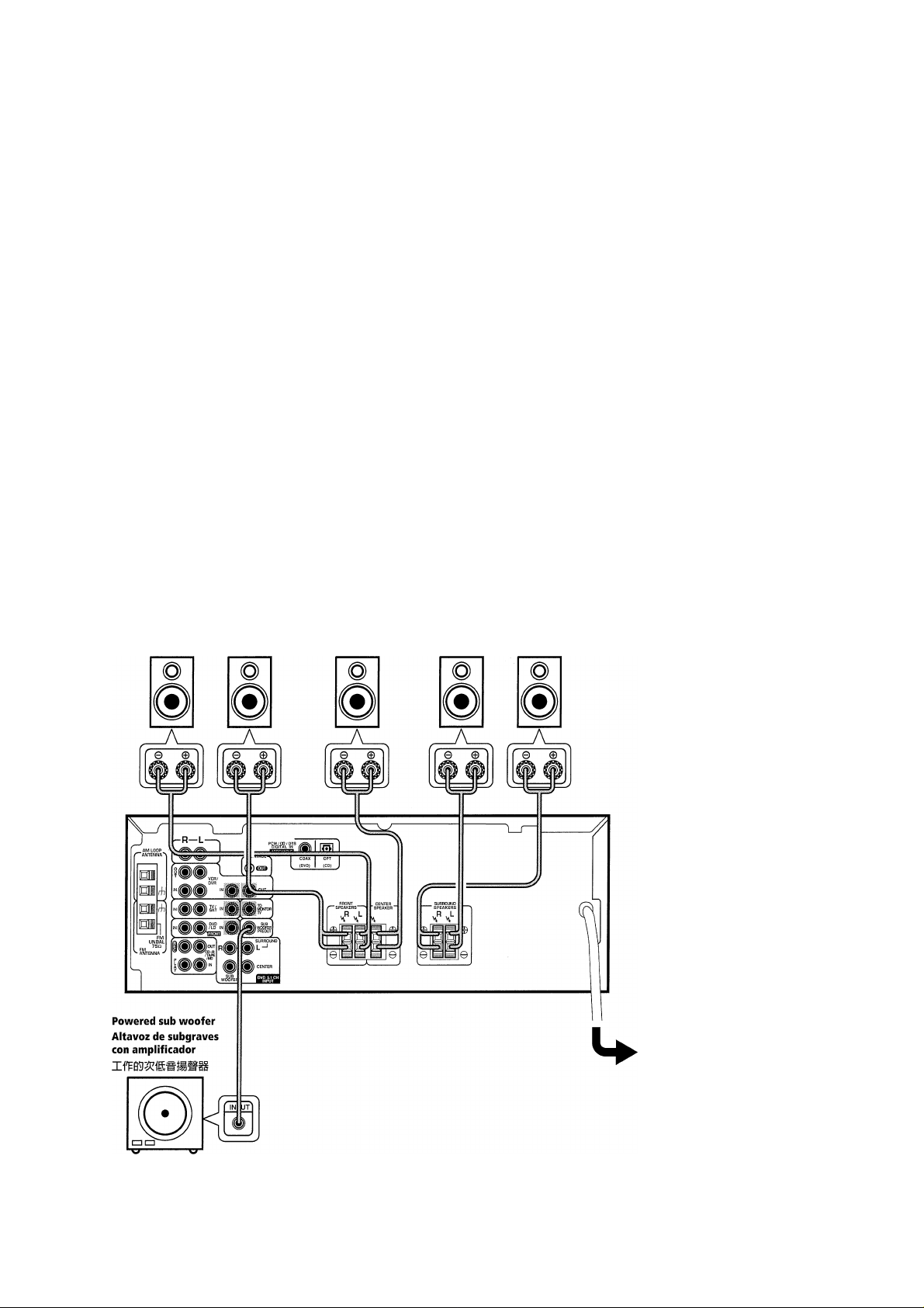
Connecting Speakers Conexión de altavoces
A full complement of six speakers is
shown here but, naturally, everyone’s
home setup will vary. Simply connect
the speakers you have in the manner
described below. The receiver will
work with just two stereo speakers
(called “front” speakers in the
diagram) but using at least three
speakers is recommended, and all five
is best.
Make sure you connect the speaker
on the right to the right terminal and
the speaker on the left to the left
terminal. Also make sure the positive
and negative (+/-) terminals on the
receiver match those on the speakers.
MEMO:
• Use speakers with a nominal
impedance of 8 Q to 16 ii.
Front Speakers
Altavoces delanteros
L R
La figura muestra un juego completo
de seis altavoces pero, por supuesto, la
instalación de cada hogar es diferente.
Conecte simplemente los altavoces que
posee de la forma descrita a
continuación. El sintoamplificador
funcionará con sólo dos altavoces
estéreo (llamados altavoces
“delanteros” en el diagrama) pero se
recomienda utilizar por lo menos tres
altavoces y los resultados óptimos se
consiguen con los cinco.
Asegúrese de conectar el altavoz de la
derecha en el terminal de la derecha y
el altavoz de la izquierda en el terminal
de la izquierda. Se debe confirmar
también que los terminales positivo y
negativo (+/-) del sintoamplificador
coinciden con los de los altavoces.
MEMO:
• Utilice altavoces de una impedancia
nominal de 8 a 16
Center Speaker
Altavoz central
c
SURROUND Speakers
Altavoces ambientales
SL
ESTEIS ÌZÈ 0^77
mm (H^«№ “#íí” mm^) m
№ ’ ^ *
± ° MSí8ÍS»^í(fi±0^íE/* ( +/
-) (+/-)
MEMO:
SR
16
En/Sp/ChH
Be sure to complete all
other connections
before connecting this
unit to the AC power
source.
Asegúrese de completar
las otras conexiones
antes de enchufar el
aparato en el
tomacorriente de CA.
;2iü ’
Speaker terminals
Use good quality speaker wire to
connect the speakers to the receiver.
1 Twist around 10mm of bare wire
strands together.
2 Unclip the speaker terminal and
insert the wire.
3 Snap shut the speaker terminal to
secure.
Terminales de altavoces
Utilice un cable de altavoz de buena
calidad para conectar los altavoces al
sintoamplificador.
1 Retuerza unos 10 mm de hilos de
cable pelados entre sí.
2 Abra el terminal de altavoz e inserte
el cable.
3 Cierre el terminal de altavoz para
asegurar el cable.
10 mm
1 ílflOmm:fe:&ÉI^S|iaSíaS-
3
d
mmm
-fio
Caution:
Make sure that all the bare speaker
wire is twisted together and inserted
fully into the speaker terminal. If any
of the bare speaker wire touches the
back panel it may cause the power to
cut off as a safety measure.
Hints on speaker
placement
Speakers are usually designed with a
particular placement in mind. Some
are designed to be floorstanding,
while others should be placed on
stands to sound their best. Some
should be placed near a wall; others
should be placed away from walls.
Follow the guidelines on placement
that the speaker manufacturer
provided with your particular
speakers to get the most out of them.
• Place the front left and right
speakers at equal distances from the
TV.
• When placing speakers near the
TV, we recommend using magneti
cally shielded speakers to prevent
possible interference, such as
discoloration of the picture when the
TV is switched on. If you do not have
magnetically shielded speakers and
notice discoloration of the TV picture,
move the speakers farther away from
the TV.
• Install the center speaker above or
below the TV so that the sound of the
center channel is localized at the TV
Precaución:
Asegúrese de que todos los hilos de
cable de altavoz expuestos quedan
enrollados entre sí y se insertan
completamente en el terminal del
altavoz. Si algún hilo de cable
expuesto del altavoz tocara el panel
trasero podría hacer que la corriente
se cortara como medida de seguridad.
Consejos para la
Instalación de los
altavoces
Los altavoces se diseñan normalmente
para colocarlos en un lugar especial.
Algunos se diseñan para colocar sobre
el piso y otros deben instalarse sobre
un soporte para que suenen mejor.
Algunos deben estar cerca de una
pared; otros deben estar alejados de las
paredes. Respete las guías de
instalación del fabricante del altavoz,
que vienen con sus altavoces, para
obtener el máximo beneficio de ellos.
• Instale los altavoces delanteros
izquierdo y derecho a la misma
distancia de su TV
• Cuando instale los altavoces cerca
del Ty se recomienda utilizar altavoces
magnéticamente blindados para evitar
las interferencias y distorsiones en el
color de la pantalla de su TV Si no
tiene altavoces magnéticamente
blindados y nota que hay una pérdida
de color en la pantalla de Ty instale los
altavoces más alejados del TV
• Instale el altavoz central sobre o
debajo del TV para que el sonido del
canal central esté localizado en la
pantalla de TV
MíiMjf asifuB » m^\í
tm « m
> mmmmm
* m±mnm
mmm >
ñ ’ wmmmmrimmnmm-
g o
TT7 >
17
En/Sp/ChH

CAUTION!
If you choose to install the
center speaker on top of the TV,
he sure to secure it with putty,
or by other suitable means, to
reduce the risk of damage or
injury resulting from the
speaker falling from the TV in
the event of external shocks
such as earthquakes.
¡PRECAUCION!
Cuando instale el altavoz
central sobre el TV, asegúrelo
con cinta u otro medio
apropiado. De lo contrario el
altavoz puede caerse del TV por
un golpe externo, por ejemplo
un terremoto, lo que puede
poner en peligro a las personas
cercanas o dañar el altavoz.
mm ’
A ’
• If possible, install the surround
speakers slightly above ear level.
• Try not to install the surround
speakers farther away from the
listening position than the front and
center speakers. Doing so can weaken
the surround sound effect.
• To achieve the best possible
surround sound, install your speakers
as shown below. Be sure all speakers
are installed securely to prevent
accidents and improve sound quality.
• Si fuera posible, instale los
altavoces ambientales ligeramente
encima del nivel de los oídos.
• Puede ser difícil obtener un efecto
ambiental coherente si se instalan los
altavoces ambientales más alejados de
la posición de escucha que los
altavoces delanteros y central.
• Para lograr el mejor sonido
ambiental posible, instale sus
altavoces tal como se indican a
continuación. Asegúrese de que todos
los altavoces están instalados
firmemente para evitar accidentes y
mejorar la calidad del sonido.
m»’ wmmmmmmmmmmmm
mn
Overhead view of speaker set up
Vista superior de la disposición de altavoces
Center
Centrai
Front Left
Delantero
izquierdo
ÍIÜ
Surround Left
Ambiental
izquierdo
Listening Position
Posición de escucha
18
En/Sp/ChH
Front Right
Delantero
derecho
e Subwoofer
H Sub graves
■
Surround Right
Ambiental
derecho
3-D view of speaker set up
Vista tridimensional de la instalación de altavoces
13-DíiB
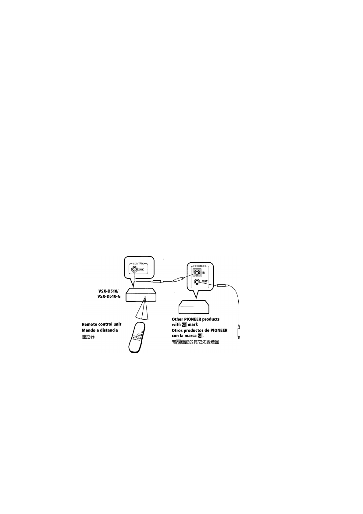
Operating Other
PIONEER Components
By connecting a control cord (op
tional), you can control other Pioneer
equipment using this remote control
unit. Point the remote control unit
towards the remote sensor of this
unit, even when operating other
equipment.
The remote control signals are
received by the remote sensor of this
unit, and sent to the other devices via
the CONTROL OUT terminal.
MEMO:
• You can also control Pioneer
components by pointing the receiver's
remote control directly at the
component. This type of operation
does not require control cords.
• Whenever making the control jack
connections, be sure to also connect
the analog input and output jacks.
System control does not function
correctly when only the digital input
and output connections are made.
Funcionamiento de otros
equipos de PIONEER
Mediante la conexión de un cable de
control (opcional) puede controla
otros equipos de Pioneer con este
mando a distancia. Apunte el mando
a distancia hacia el sensor a distancia
de esta unidad, aunque desee hacer
funcionar los otros equipos.
Las señales del mando a distancia se
reciben mediante el sensor a distancia
de esta unidad y se transmite a los
otros equipos a través del terminal
CONTROL OUT.
MEMO:
• También puede controlar equipos
de Pioneer apuntando directamente el
mando a distancia del sintoamplificador
hacia el equipo. Este tipo de uso no
requiere cables de control.
• Al realizar las conexiones de la toma
de control, asegúrese de conectar
también las tomas de entrada y salida
analógicas. El control del sistema no
funciona correctamente cuando sólo se
realizan las conexiones digitales de
entrada y de salida.
G
(íí^) ’MA
íi ° ’ M
íá ’ as CONTROL OUT (Sflillll
MEMO:
UiÍff»5ÍflAfPfiíÜlíÍ?Lfi^aif
Connect to CONTROL IN terminal of
other PIONEER products with p] mark.
Conecte al terminal CONTROL IN de
otros productos de PIONEER con la
marca H|.
CONTROL
IN °
En/Sp/ChH
19

Preparations Preparativos
Setting Up for Surround Ajustes para sonido
Sound ambiental
Switch the power of this unit on (The
STANDBY indicator goes out).
To ensure the best possible surround
sound, be sure to complete the
following set up operations. This is
particularly important when using the
□□ (Dolby) surround mode. You only
need to make these settings once
(unless you change the placement of
your current speaker system or add
new speakers, etc.). Refer to the
following pages for detailed descrip
tions of the settings available for each
mode.
1 Press (!) RECEIVER to turn
the power on.
The STANDBY indicator goes out.
2 Press RECEIVER.
This switches the remote to the
receiver mode.
3 Press <1 or > to select the
mode you want to set.
For best results, start with “SPEAK
ERS setting mode” and make your
initial adjustments in the order
described below.
The current settings are displayed
automatically.
• SPEAKERS (Eront, Center,
Surround) setting mode (page 22)
Use to specify the number and type of
speakers you have connected.
• SUBWOOEER ON/PLUS/OFF
setting mode (page 23)
Use to specify the subwoofer as on,
plus or off.
• Crossover frequency setting
mode (page 24)
Use to determine which frequencies
will be sent to the subwoofer (or
“Large” speakers if you don’t have a
subwoofer).
• LEE attenuator setting mode
(page 25)
Use to specify the peak level for the
LEE channel and the crossover
network for rerouted bass frequen-
20
En/Sp/ChH
Encienda la alimentación de este
aparato (se apaga el indicador
STANDBY).
Para que el sonido ambienta sea el
mejor posible, realice todos los
siguientes procedimientos de ajuste.
Esto es particularmente importante
cuando utilice el modo □□ (DOLBY).
Es necesario hacer estos ajustes sólo
una vez (a menos que cambie el lugar
de instalación del sistema de altavoces
actual o agregue nuevos altavoces, etc.)
Consulte las siguientes páginas para
descripciones más detalladas de los
ajustes disponibles para cada modo.
1 Presione (!) RECEIVER para
conectar la alimentación.
Se apaga el indicador STANDBY.
2 Presione RECEIVER.
Esto pone el mando a distancia en el
modo del sintoamplificador.
3 Presione <1 o > para
seleccionar el modo que desea
ajustar.
Para obtener mejores resultados,
empiece con el “Modo de ajuste de
altavoces” y haga sus ajustes iniciales
en el orden que se describe a
continuación.
Los ajustes vigentes aparecen
automáticamente.
• Modo de ajuste de altavoces
(delanteros, central, ambientales)
(página 22)
Utilice para especificar el número y
tipo de altavoces que ha conectado.
• Modo de ajuste de subgraves
activado/Plus/desactivado (página
23)
Utilice para especificar si el subgraves
está activado, plus o desactivado.
• Modo de ajuste de frecuencia de
cruce (página 24)
Utilice para determinar las frecuencias
que se asignan al altavoz de subgraves
(o altavoces “grandes” si no tiene un
altavoz de subgraves).
• Modo de ajuste del atenuador
LEE (página 25)
Utilice para especificar el nivel pico del
canal LEE y la red de cruza para
cambiar la asignación de las
frecuencias bajas.
»iizfp
(STANDBY (íiffl) íg
7KÍI®«) °
mimmmimmmm ’
fÄrmmim ° m-mmmuu
(ttht) ° íl
mmmm) °
mm ’ 0rmrm °
1 ÍST (!) RECEIVER (Ô ígUÍ
H) fôlB - íiSWJi »
íifflíi»« »
2 }^T RECEIVER (JgM)
mmnm&mmmumim »
3
BIIîT ’ iÉSTaii/ÎiifîW
fâsœ »
• mmm (lüssgi ' .
(m22m)
' mw
mñm »
• (fg24M)
mmm) mmmm °
• LFE
(^25M)

(Q
• Low cut filter ON/OFF setting
mode (page 25)
Use to cut the distorted sound from
the subwoofer.
• FRONT speakers distance
setting mode (page 25)
Use to specify the distance from your
listening position to your front
speakers.
• CENTER speakers distance
setting mode (page 26)
Use to specify the distance from your
listening position to your center
speaker.
• SURROUND speakers distance
setting mode (page 26)
Use to specify the distance from your
listening position to your surround
speakers.
• Dynamic range control setting
mode (page 27)
Use to compress the dynamic range of
the sound track.
• Dual mono setting (page 28)
Use with □□ Digital software that has
dual mono encoding if you want to
isolate one channel or listen in this
specialized mono mode.
• Coaxial digital input setting
(page 29)
Use to specify the component to be
assigned to the coaxial digital input.
• Optical digital input setting
(page 29)
Use to specify the component to be
assigned to the optical digital input.
4 Press A or V to select the setting you want.
The setting is entered automatically.
5 Repeat steps 3 and 4 to set other surround modes.
MEMO:
Press ENTER to exit the setting mode.
The setting mode is automatically
exited if no operation is performed
within 20 seconds.
• Modo de activación/desactivación
del filtro de corte de bajos (página
25)
Utilice para cortar el sonido
distorsionado del altavoz de subgraves.
• Modo de ajuste de distancia de
los altavoces delanteros (página 25)
Utilice para especificar la distancia
desde su posición de escucha a sus
altavoces delanteros.
• Modo de ajuste de distancia del
altavoz central (página 26)
Utilice para especificar la distancia
desde su posición de escucha a su
altavoz central.
• Modo de ajuste de distancia de
los altavoces ambientales (página
26)
Utilice para especificar la distancia
desde su posición de escucha a sus
altavoces ambientales.
• Modo de ajuste de control de
gama dinámica (página 27)
Utilice para comprimir la gama
dinámica de su pista de sonido.
• Modo de ajuste dual monofònico
(página 28)
Utilice con el software digital □□ que
tiene codificación dual monofònico si
desea aislar un canal o escuchar este
modo.monofònico especializado.
• Modo de ajuste de entrada digital
coaxial (página 29)
Utilice para especificar el componente
a asignar a la entrada digital coaxial.
• Modo de ajuste de entrada digital
óptica (página 29)
Utilice para especificar el componente
a asignar a la entrada digital óptica.
4 Presione A o V para
seleccionar el ajuste deseado.
El ajuste queda seleccionado
automáticamente.
5 Repita los pasos 3 y 4 para
ajustar otros modos ambientales.
MEMO:
Presione ENTER para salir del modo
de ajuste.
Se sale automáticamente del modo de
ajuste si no se hace ninguna operación
dentro 20 segundos.
se (m25M)
• (^26
M)
• (ig26
M)
»
• (S27M)
. «üSffligB (S28M)
• |B||ÍB9:ÍSIAiaB (^29M)
(¡mw »
• (S29M)
4 íSTAsEvísia.
lafigitifiA °
5 3 w 4 -
MEMO:
STE
énSí
21
En/Sp/ChH

SPEAKERS (Front, Center,
Surround) setting mode
This setting establishes the configura
tion of the speaker system and size of
each set of speakers you have
connected. So, for example, here you
set whether you have connected
surround speakers or not, and how
big they are. Selecting “Large” or
“Small” will determine how much
bass is sent by the receiver to the
speakers being set.
In the display, “F”, “C”, and “S” refer
to front, center, and surround
speakers respectively. Speaker size is
denoted as “L” for large speakers, “S”
for small speakers, and “*” (asterisk)
if no speaker is connected.
MEMO:
If the cone size (diameter) of the
speaker is larger than 12 cm, please
set to Large.
Choose a speaker setting mode
according to the speakers you
hooked up. Use the A or V
buttons.
The configurations shown below will
appear in the display on the front of
the receiver. One of them should
match your speaker set up. Cycle
through the different possibilities
until you find the one that matches
your set up.
Press > to advance to the next
receiver setting, and press < to return
to a previous receiver setting.
Modo de ajuste de altavoces
(delanteros, central,
ambientales)
Este ajuste determina la configuración
del sistema de altavoces y el tamaño de
cada conjunto de altavoces que haya
conectado. Se puede ajustar, por
ejemplo si se han conectado los
altavoces ambientales o no y su
tamaño. Seleccione “Large” (grande) o
“Small” (pequeño) para determinar la
cantidad de graves transmitidos por el
sintoamplificador a los altavoces
instalados.
En la pantalla “F”, “C” y “S” se refieren
respectivamente a los altavoces
delanteros, central y ambientales. El
tamaño del altavoz se describe como
“L” para los altavoces grandes y “S”
para los pequeños, y “*” (asterisco)
cuando no se han conectado.
MEMO:
Si el tamaño (diámetro) del cono del
altavoz es mayor de 12 cm, seleccione
Grande.
Elija un modo de ajuste de
altavoces de acuerdo a los
altavoces conectados. Utilice los
botones A o V.
Las configuraciones de la derecha
aparecen en la pantalla delantera del
sintoamplificador. Uno de ellos debe
coincidir con su instalación de
altavoces. Avance en un ciclo por las
diferentes posibilidades hasta
encontrar el que corresponde a su
instalación.
mms immmn ^
n ’ üiRmMmm»mw “±"
m “/]n”
SB/KfflJ: ’ “F”
“L” ’
“s” ’ ’ iiJffl
MEMO:
12cm > Íf|SB/5]c “i\" °
gElES^IBfi “
“C” “S”
(BS )
22
En/Sp/ChH
C 1 1
1 L í
c: c .. í
1 „1 L: * -
C C .. 1
1 J l
L "
” r: „
„ j
.J L
5 5
5 *
Presione > para avanzar al siguiente
ajuste del sintoamplificador y presione
<] para volver al ajuste anterior del
sintoamplificador.
1
r I „ r I .. r
I L L L -.1 -j
^
-----
c r; „ r r: „ r; r:
► 1 J L -J J J
^
......
-----
c.
1
►
^ " 5
c 1 .. r r;
1 L L. J
c 1 „ r r:
1 L L J " b b
c 1 .. r r:
1 L L J
l
i í
i
„ r 1
í
.. C \!l
J /1'
í
FL -f;* - 5 i
J L
 Loading...