

Page 1
VSX-819H
-S/-K
Page 2
The exclamation point within an equilateral
triangle is intended to alert the user to the
presence of important operating and
maintenance (servicing) instructions in the
literature accompanying the appliance.
The lightning flash with arrowhead symbol,
within an equilateral triangle, is intended to
alert the user to the presence of uninsulated
"dangerous voltage" within the product's
enclosure that may be of sufficient
magnitude to constitute a risk of electric
shock to persons.
CAUTION:
TO PREVENT THE RISK OF ELECTRIC
SHOCK, DO NOT REMOVE COVER (OR
BACK). NO USER-SERVICEABLE PARTS
INSIDE. REFER SERVICING TO QUALIFIED
SERVICE PERSONNEL.
CAUTION
RISK OF ELECTRIC SHOCK
DO NOT OPEN
IMPORTANT
D3-4-2-1-1_En-A
Thank you for buying this Pioneer product.
Please read through these operating instructions so
you will know how to operate your model properly.
After you have finished reading the instructions,
put them away in a safe place for future reference.
WARNING
To prevent a fire hazard, do not place any naked
flame sources (such as a lighted candle) on the
equipment.
D3-4-2-1-7a_A_En
WARNING
This equipment is not waterproof. To prevent a fire
or shock hazard, do not place any container filled
with liquid near this equipment (such as a vase or
flower pot) or expose it to dripping, splashing, rain
or moisture.
D3-4-2-1-3_B_En
WARNING
The voltage of the available power supply differs
according to country or region. Be sure that the
power supply voltage of the area where this unit
will be used meets the required voltage (e.g., 230 V
or 120 V) written on the rear panel.
D3-4-2-1-4_A_En
Before plugging in for the first time, read the following
section carefully.
Operating Environment
Operating environment temperature and humidity:
+5 ºC to +35 ºC (+41 ºF to +95 ºF); less than 85 %RH
(cooling vents not blocked)
Do not install this unit in a poorly ventilated area, or in
locations exposed to high humidity or direct sunlight (or
strong artificial light)
D3-4-2-1-7c_A_En
This product is for general household purposes. Any
failure due to use for other than household purposes
(such as long-term use for business purposes in a
restaurant or use in a car or ship) and which
requires repair will be charged for even during the
warranty period.
K041_En
Replacement and mounting of an AC plug on the power supply cord of this unit should be performed only by qualified
service personnel.
D3-4-2-1-2-2_B_En
IMPORTANT: THE MOULDED PLUG
This appliance is supplied with a moulded three pin mains plug for your safety and convenience. A 10 amp fuse is fitted in this plug. Should the
fuse need to be replaced, please ensure that the replacement fuse has a rating of 10 amps and that it is approved by ASTA or BSI to BS1362.
Check for the ASTA mark or the BSI mark on the body of the fuse.
If the plug contains a removable fuse cover, you must ensure that it is refitted when the fuse is replaced. If you lose the fuse cover the plug
must not be used until a replacement cover is obtained. A replacement fuse cover can be obtained from your local dealer.
If the fitted moulded plug is unsuitable for your socket outlet, then the fuse shall be removed and the plug cut off and disposed of
safely. There is a danger of severe electrical shock if the cut off plug is inserted into any 13 amp socket.
If a new plug is to be fitted, please observe the wiring code as shown below. If in any doubt, please consult a qualified electrician.
IMPORTANT: The wires in this mains lead are coloured in accordance with the following code:
Blue : Neutral Brown : Live
As the colours of the wires in the mains lead of this appliance may not correspond with the coloured markings identifying the terminals in your
plug, proceed as follows ;
The wire which is coloured BLUE must be connected to the terminal which is marked with the
letter N or coloured BLACK.
The wire which is coloured BROWN must be connected to the terminal which is marked with the
letter L or coloured RED.
How to replace the fuse: Open the fuse compartment with a screwdriver and replace the fuse.
Page 3
BAND
PHONES
INPUT
SELECTOR
STANDBY/ON
AUTO SURROUND/
STREAM DIRECT
STEREO/
A.L.C.
ADVANCED
SURROUND
STANDARD
SURROUND
MASTER
VOLUME
SPEAKERS
CONTROL
MULTI-ZONE
ON/OFF
TUNER
EDIT
ENTER
AUDI
O
/
VIDEO MULTI
-CHANNEL
RECEIVER
TUNE
–
TUNE
+
PRESET
–
PRESET
+
VENTILATION CAUTION
When installing this unit, make sure to leave space
around the unit for ventilation to improve heat
radiation (at least 60 cm at top, 10 cm at rear, and
30 cm at each side).
WARNING
Slots and openings in the cabinet are provided for
ventilation to ensure reliable operation of the
product, and to protect it from overheating. To
prevent fire hazard, the openings should never be
blocked or covered with items (such as newspapers,
table-cloths, curtains) or by operating the
equipment on thick carpet or a bed.
D3-4-2-1-7b_A_En
If the AC plug of this unit does not match the AC
outlet you want to use, the plug must be removed
and appropriate one fitted. Replacement and
mounting of an AC plug on the power supply cord of
this unit should be performed only by qualified
service personnel. If connected to an AC outlet, the
cut-off plug can cause severe electrical shock. Make
sure it is properly disposed of after removal.
The equipment should be disconnected by removing
the mains plug from the wall socket when left
unused for a long period of time (for example, when
on vacation).
D3-4-2-2-1a_A_En
CAUTION
The STANDBY/ON switch on this unit will not
completely shut off all power from the AC outlet.
Since the power cord serves as the main disconnect
device for the unit, you will need to unplug it from
the AC outlet to shut down all power. Therefore,
make sure the unit has been installed so that the
power cord can be easily unplugged from the AC
outlet in case of an accident. To avoid fire hazard,
the power cord should also be unplugged from the
AC outlet when left unused for a long period of time
(for example, when on vacation).
D3-4-2-2-2a_A_En
Manufactured under license from Dolby
Laboratories. Dolby, Pro Logic, Surround EX
and the double-D symbol are trademarks of
Dolby Laboratories.
D3-4-2-1-5_En
Voltage selector
You can find the voltage selector switch on the rear
panel of multi-voltage models.
The factory setting for the voltage selector is
220-240 V. Please set it to the correct voltage for
your country or region.
• Saudi Arabia operates on 127 V and 220 V mains
voltage. Please set to the correct voltage before using.
• For Taiwan, please set to 110-127 V before using.
• For Mexico, please set to 110-127 V before using.
Before changing the voltage, disconnect the AC power
cord. Use a medium size screwdriver to change the
voltage selector switch.
For Taiwan exclusively
Taiwanese two pin flat-bladed plug
Medium size
screwdriver
Manufactured under license under U.S.
Patent #’s: 5,451,942; 5,956,674; 5,974,380;
5,978,762; 6,226,616; 6,487,535 & other U.S.
and worldwide patents issued & pending.
DTS is a registered trademark and the DTS
logos, Symbol, DTS-HD and DTS-HD Master
Audio are trademarks of DTS, Inc. ©
1996-2007 DTS, Inc. All Rights Reserved.
A warning that excessive sound pressure
from earphones and headphones can cause
hearing loss.
These symbols are only valid
in the European Union.
K058c_A1_En
(Symbol examples for batteries)
Pb
Page 4

NOTE:
This equipment has been tested and found to comply with the limits for a Class B digital device, pursuant to Part 15
of the FCC Rules. These limits are designed to provide reasonable protection against harmful interference in a
residential installation. This equipment generates, uses, and can radiate radio frequency energy and, if not installed
and used in accordance with the instructions, may cause harmful interference to radio communications. However,
there is no guarantee that interference will not occur in a particular installation. If this equipment does cause
harmful interference to radio or television reception, which can be determined by turning the equipment off and on,
the user is encouraged to try to correct the interference by one or more of the following measures:
— Reorient or relocate the receiving antenna.
— Increase the separation between the equipment and receiver.
— Connect the equipment into an outlet on a circuit different from that to which the receiver is connected.
— Consult the dealer or an experienced radio/TV technician for help.
D8-10-1-2_A1_En
Information to User
Alterations or modifications carried out without appropriate authorization may invalidate the user’s right to operate
the equipment.
D8-10-2_A1_En
CAUTION
This product satisfies FCC regulations when shielded cables and connectors are used to connect the unit to other
equipment. To prevent electromagnetic interference with electric appliances such as radios and televisions, use
shielded cables and connectors for connections.
D8-10-3a_A1_En
FEDERAL COMMUNICATIONS COMMISSION DECLARATION OF CONFORMITY
This device complies with part 15 of the FCC Rules. Operation is subject to the following two conditions: (1) This
device may not cause harmful interference, and (2) this device must accept any interference received, including
interference that may cause undesired operation.
Product Name: AUDIO/VIDEO MULTI-CHANNEL RECEIVER
Model Number: VSX-819H-K / VSX-819H-S
Responsible Party Name: PIONEER ELECTRONICS SERVICE, INC.
Address: 1925 E. DOMINGUEZ ST. LONG BEACH, CA 90801-1760, U.S.A.
Phone: 1-800-421-1404
D8-10-4*_A1_En
Page 5

Contents
01 Before you start
Checking what’s in the box . . . . . . . . . . . . . . . 7
Loading the batteries. . . . . . . . . . . . . . . . . . . . 7
Installing the receiver . . . . . . . . . . . . . . . . . . . 7
Ventilation . . . . . . . . . . . . . . . . . . . . . . . . . . 7
02 5 minute guide
Introduction to home theater. . . . . . . . . . . . . . 8
Listening to Surround Sound. . . . . . . . . . . . . . 8
Automatically setting up for surround sound
(MCACC) . . . . . . . . . . . . . . . . . . . . . . . . . . . . . 9
Other problems when using the
Auto MCACC Setup . . . . . . . . . . . . . . . . . . 11
Better sound using Phase Control. . . . . . . . . 11
03 Connecting up
Making cable connections . . . . . . . . . . . . . . 12
HDMI cables. . . . . . . . . . . . . . . . . . . . . . . . 12
About HDMI . . . . . . . . . . . . . . . . . . . . . . . . 12
Analog audio cables . . . . . . . . . . . . . . . . . . 13
Digital audio cables . . . . . . . . . . . . . . . . . . 13
Video cables . . . . . . . . . . . . . . . . . . . . . . . . 13
About video outputs connection . . . . . . . . . . 13
Connecting a TV and Blu-ray Disc player
or DVD player . . . . . . . . . . . . . . . . . . . . . . . . 14
Connecting the multichannel analog
outputs . . . . . . . . . . . . . . . . . . . . . . . . . . . . 15
Connecting a satellite receiver or other
digital set-top box . . . . . . . . . . . . . . . . . . . . . 16
Connecting other audio components . . . . . . 17
Connecting an HDD/DVD recorder, VCR
and other video sources . . . . . . . . . . . . . . . . 18
Using the component video jacks . . . . . . . . . 19
Connecting to the front panel video
terminal. . . . . . . . . . . . . . . . . . . . . . . . . . . . . 20
Connecting antennas . . . . . . . . . . . . . . . . . . 20
Using external antennas . . . . . . . . . . . . . . . 21
Connecting the speakers. . . . . . . . . . . . . . . . 22
Use the PRE OUT outputs to connect
the surround back speakers . . . . . . . . . . . . 23
Placing the speakers . . . . . . . . . . . . . . . . . 24
Switching the speaker system . . . . . . . . . . 25
Connecting an IR receiver . . . . . . . . . . . . . . . 25
Plugging in the receiver . . . . . . . . . . . . . . . . 26
05 Listening to your system
Auto playback . . . . . . . . . . . . . . . . . . . . . . . . 34
Listening in surround sound . . . . . . . . . . . . . 34
Using the Advanced surround effects . . . . .35
Listening in stereo . . . . . . . . . . . . . . . . . . . . . 36
Using Front Stage Surround Advance . . . . . . 36
Using Stream Direct . . . . . . . . . . . . . . . . . . .37
Using the Sound Retriever. . . . . . . . . . . . . . . 37
Listening with Acoustic Calibration EQ . . . . . 37
Using surround back channel processing . . . 37
Setting the Up Mix function . . . . . . . . . . . . . . 38
Setting the Audio options . . . . . . . . . . . . . . . 39
Playing other sources . . . . . . . . . . . . . . . . . .41
Choosing the input signal . . . . . . . . . . . . . . . 41
Selecting the multichannel analog inputs . . . 41
Using the headphone . . . . . . . . . . . . . . . . . . 41
06 The System Setup menu
Using the System Setup menu . . . . . . . . . . . 42
Manual speaker setup . . . . . . . . . . . . . . . . . . 42
Speaker Setting. . . . . . . . . . . . . . . . . . . . . . 43
Crossover Network . . . . . . . . . . . . . . . . . . . 44
Channel Level . . . . . . . . . . . . . . . . . . . . . . . 44
Speaker Distance . . . . . . . . . . . . . . . . . . . . 45
The Input Assign menu . . . . . . . . . . . . . . . . . 45
07 Using the MULTI-ZONE feature
MULTI-ZONE listening . . . . . . . . . . . . . . . . . . 47
Making MULTI-ZONE connections . . . . . . . 47
Using the MULTI-ZONE controls . . . . . . . . . 48
08 Using the tuner
Listening to the radio . . . . . . . . . . . . . . . . . . . 49
Improving FM stereo sound. . . . . . . . . . . . . 49
Saving station presets . . . . . . . . . . . . . . . . . . 49
Listening to station presets . . . . . . . . . . . . . 50
Naming preset stations. . . . . . . . . . . . . . . . 50
Changing the frequency step. . . . . . . . . . . . . 50
09 Making recordings
Making an audio or a video recording . . . . . . 51
English
English Italiano Français
Français
Italiano
Nederlands
Español
Nederlands
Deutsch
EspañolDeutsch
04 Controls and displays
Front panel . . . . . . . . . . . . . . . . . . . . . . . . . . 27
Operating range of remote control . . . . . . . 28
Display . . . . . . . . . . . . . . . . . . . . . . . . . . . . . 29
Remote control . . . . . . . . . . . . . . . . . . . . . . . 31
5
En
Page 6

10 Controlling the rest of your
system
Setting the remote to control other
components . . . . . . . . . . . . . . . . . . . . . . . . . 52
Selecting preset codes directly . . . . . . . . . . . 52
Clearing all the remote control settings . . . . 52
Controls for TVs. . . . . . . . . . . . . . . . . . . . . . . 53
Controls for other components . . . . . . . . . . . 54
Preset Code List . . . . . . . . . . . . . . . . . . . . . . 56
11 Other connections
Connecting an iPod . . . . . . . . . . . . . . . . . . . 61
Connecting your iPod to the receiver . . . . . 61
iPod playback . . . . . . . . . . . . . . . . . . . . . . . 62
Watching photos and video content . . . . . . 63
About iPod . . . . . . . . . . . . . . . . . . . . . . . . . 63
Connecting a USB device . . . . . . . . . . . . . . . 64
Connecting your USB device to the
receiver . . . . . . . . . . . . . . . . . . . . . . . . . . . 64
Basic playback controls . . . . . . . . . . . . . . . 64
Compressed audio compatibility . . . . . . . . 65
12 Additional information
Troubleshooting . . . . . . . . . . . . . . . . . . . . . . 66
HDMI . . . . . . . . . . . . . . . . . . . . . . . . . . . . . 68
Important information regarding the
HDMI connection . . . . . . . . . . . . . . . . . . . . 68
iPod messages . . . . . . . . . . . . . . . . . . . . . . 69
USB messages. . . . . . . . . . . . . . . . . . . . . . 69
Changing the TV format setting. . . . . . . . . . . 70
Resetting the main unit. . . . . . . . . . . . . . . . . 70
Specifications . . . . . . . . . . . . . . . . . . . . . . . . 70
Cleaning the unit . . . . . . . . . . . . . . . . . . . . . 71
6
En
Page 7
Before you start 01
60 cm
Receiver
Chapter 1:
Before you start
Checking what’s in the box
Please check that you’ve received the following
supplied accessories:
•Setup microphone
• Remote control
•Dry cell batteries (AAA size IEC R03) x2
•AM loop antenna
•FM wire antenna
•iPod cable
•Power cords x3 (make sure you use the
correct cord for your country/region):
Round 2-pin type, flat blade 2-pin type and
UK 3-pin type
•These operating instructions
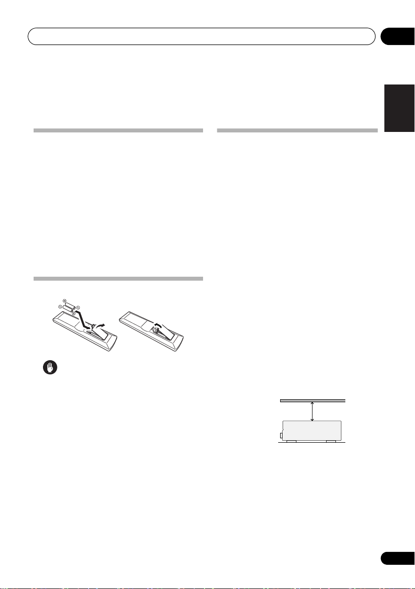
Loading the batteries
Caution
Incorrect use of batteries may result in such
hazards as leakage and bursting. Observe the
following precautions:
• Never use new and old batteries together.
• Insert the plus and minus sides of the
batteries properly according to the marks
in the battery case.
• Batteries with the same shape may have
different voltages. Do not use different
batteries together.
•When disposing of used batteries, please
comply with governmental regulations or
environmental public instruction’s rules
that apply in your country or area.
• Do not use or store batterie
sunlight or other ex
such as inside a car or near a heater. This
can cause batteries to leak, overheat,
explode or catch fire. It can also reduce the
life or performance of batteries.
s in direct
cessively hot place,
Installing the receiver
• When installing this unit, make sure to put
Don’t install it on the following places:
– on a color TV (the screen may distort)
– near a cassette deck (or close to a device
that gives off a magnetic field). This may
interfere with the sound.
– in direct sunlight
– in damp or wet areas
– in extremely hot or cold areas
– in places where there is vibration or other
movement
– in places that are very dusty
– in places that have hot fumes or oils (such
as a kitchen)
Ventilation
When installing this unit, make sure to leave
space around the unit for ventilation to improve
heat dispersal (at least 60 cm at the top). If
not enough space is provided between the
unit and walls or other equipment, heat will
build up inside, interfering with performance
and/or causing malfunctions.
Slot and openings in the cabinet are provided
for ventilation and to protect the equipment
from overheating. To prevent fire hazard, do
not place anything directly on top of the unit,
make sure the openings are never blocked or
covered with items (such as newspapers,
table-cloths and curtains), and do not operate
the eq
it on a level and stable surface.
uipment on
thick carpet or a bed.
English
English
Français
Français
Italiano
Italiano
Nederlands
Nederlands
Español
Español
Deutsch
Deutsch
7
En
Page 8
5 minute guide02
Chapter 2:
5 minute guide
Introduction to home theater
Home theater refers to the use of multiple
audio tracks to create a surround sound effect,
making you feel like you’re in the middle of the
action or concert. The surround sound you get
from a home theater system depends not only
on your speaker setup, but also on the source
and the sound settings of the receiver.
This receiver will automatically decode
multichannel Dolby Digital, DTS, or Dolby
Surround sources according to your speaker
setup. In most cases, you won’t have to make
changes for realistic surround sound, but
other possibilities (like listening to a CD with
multichannel surround sound) are explained in
Listening to your system on page 34.
Listening to Surround Sound
With the following quick setup guide, you
should have your system hooked up for
surround sound in no time at all. In most
cases, you can simply leave the receiver in the
default settings.
•Be sure to complete all connections before
connecting to an AC power source.
1 Connect your TV and Blu-ray Disc player
or DVD player.
See Connecting a TV and Blu-ray Disc player or
DVD player on page 14 to do this. For surround
sound, you’ll want to hook up using a digital
connection from the BD/DVD player to the
receiver.
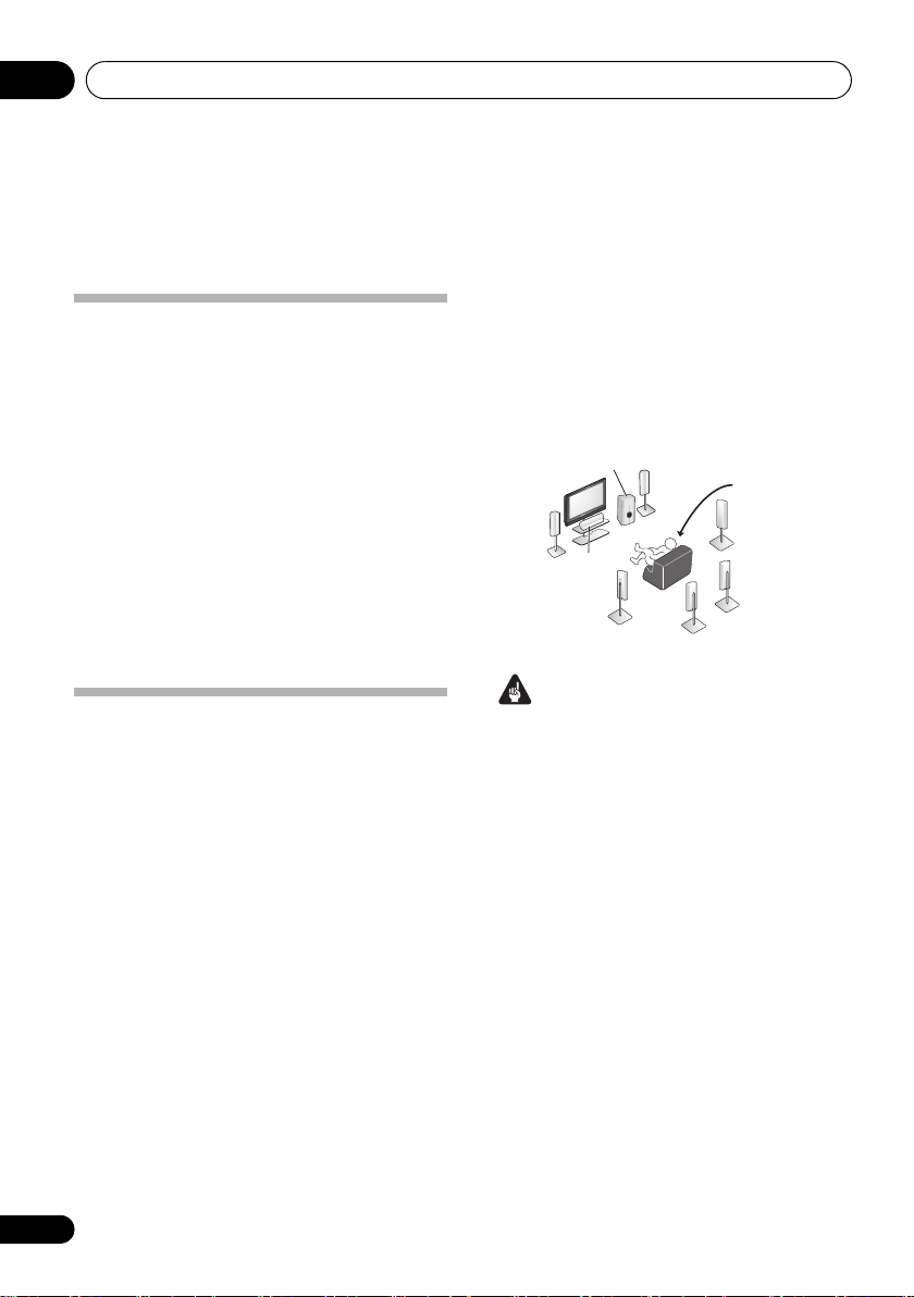
2 Connect your speakers and place them for
optimal surround sound.
See Connecting the speakers on page 22.
Where you place the speakers will have a big
effect on the sound. Place your speakers as
shown below for the best surround sound
effect. Also see Placing the speakers on page 24
for more on this.
Subwoofer (SW)
Front
Left (L)
Surround
Left (SL)
Center (C)
Front
Right (R)
Surround Back
Left (SBL)
Listening
position
Surround
Right (SR)
Surround Back
Right (SBR)
Important
• To connect the surround back speakers, an
additional amplifier is required. Connect
the additional amplifier to the PRE OUT
SURROUND BACK outputs of this unit and
connect the surround back speakers to the
additional amplifier. For details, see Use
the PRE OUT outputs to connect the
surround back speakers on page 23.
3 Plug in and switch on the receiver, followed
by your BD/DVD player, subwoofer and TV.
Make sure you’ve set the video input on your TV
to this receiver. Check the manual that came
with the TV if you don’t know how to do this.
4 Use the on-screen automatic MCACC
setup to set up your system.
See Automatically setting up for surround
sound (MCACC) on page 9 for more on this.
8
En
Page 9
5 minute guide 02
Note
BD TV
INPUT SELECT
SOURCE
DVR
INPUT
TV CONTROL
RECEIVER
ZONE 2
ON/OFF
RETURN
RECEIVER
ENTER
SETUP
RECEIVER
PTY SEARCH
D
System Setup
1.Auto MCACC
2.Manual SP Setup
3.Input Assign
Return
5 Play a BD/DVD, and adjust the volume.
Make sure that
receiver’s display. If it isn’t, press
BD/DVD
is showing in the
BD
on the
remote to set the receiver to the BD/DVD input.
There are several other sound options you can
select. See Listening to your system on page 34
for more on this.
2
Automatically setting up for surround sound (MCACC)
The Auto Multi-Channel Acoustic Calibration
(MCACC) setup measures the acoustic
characteristics of your listening area, taking
into account ambient noise, speaker size and
distance, and tests for both channel delay and
channel level. After you have set up the
microphone provided with your system, the
receiver uses the information from a series of
test tones to optimize the speaker settings and
equalization for your particular room.
Important
• The Auto MCACC Setup will overwrite any
existing speaker settings you’ve made.
•Before using the Auto MCACC Setup, the
iPod USB function should not be selected
as an input source.
Caution
• The test tones used in the Auto MCACC
Setup are output a
t high volume.
AUDIO
PARAMETER
N
U
E
T
TOP
MENU
T
E
S
ENTER
E
R
P
HOME
MENU
T
SETUP
E
U
N
iPod
CTRL
PTY SEARCH
TUNER EDIT
TOOLS
MENU
P
R
E
S
E
T
BAND
RETURN
MASTER
VOLUME
Switch on the receiver and your TV.
1
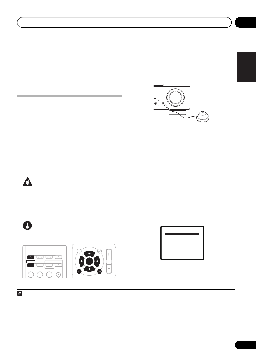
2 Connect the microphone to the
SETUP MIC
1
jack on the front panel.
Make sure there are no obstacles between the
speakers and the microphone.
ENTER
IO
R
MCACC
SETUP MIC
MASTER
VOLUME
If you have a tripod, use it to place the
microphone so that it’s about ear level at your
normal listening position. Otherwise, place the
microphone at ear level using a table or a chair.
3Press
then press the
RECEIVER
SETUP
on the remote control,
button.
An on-screen display (OSD) appears on your
TV. Use /// and ENTER on the remote
control to navigate through the screens and
select menu items. Press RETURN to exit the
current menu.
•Press SETUP at any time to exit the System
Setup menu.
3
4 Select ‘Auto MCACC’ from the System
4
Setup menu then press ENTER.
Try to be as quiet as possible after pressing
ENTER. The system outputs a series of test
tones to establish the ambient noise level.
MCACC
English
Français
Italiano
Nederlands
Español
Deutsch
1 You may need to set your BD/DVD player to output Dolby Digital, DTS and 88.2 kHz/96 kHz PCM (2 channel) audio (see your
BD/DVD player’s manual for more on this).
2Depending on your BD/DVD player or source disc, you may only get 2 channel sound. In this case, the listening mode must be
set to STANDARD (see Listening in surround sound on page 34 if you need to do this) if you want multichannel surround sound.
3• The screensaver automatically starts after three minutes of inactivity. If you cancel the Auto MCACC Setup at any time, the
receiver automatically exits and no settings will be made.
• The OSD will not appear if you have connected using the HDMI output to your TV. Use component or composite connections
for system setup.
4 MIC IN blinks when the microphone is not connected to MCACC SETUP MIC.
9
En
Page 10
5 minute guide02
Note
5 Follow the instructions on-screen.
•Make sure the microphone is connected.
•Make sure the subwoofer is on and the
volume is turned up.
•See below for notes regarding background
noise and other possible interference.
6 Wait for the test tones to finish.
A progress report is displayed on-screen while
the receiver outputs test tones to determine the
speakers present in your setup. Try to be as
quiet as possible while it’s doing this.
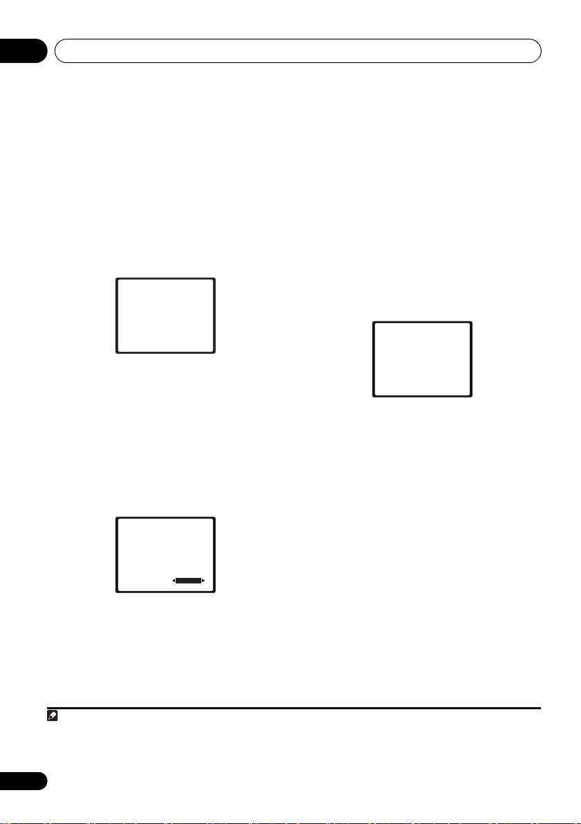
1.Auto MCACC
Now Analyzing
Environment Check
Ambient Noise
Speaker YES/NO
Return
•For correct speaker settings, do not adjust
the volume during the test tones.
7 Confirm the speaker configuration.
The configuration shown on-screen should
reflect the actual speakers you have.
•With error messages (such as Too
m
uch
ambient noise) select RETRY after
checking for ambient noise (see Other
problems when using the Auto MCACC
Setup on page 11).
1.Auto MCACC
Check!
[ YES ]
Front
[ YES ]
Center
[ YES ]
Surr
[YESx2]
Surr. Back
[ YES ]
Subwoofer
10:Next
OK
Return
If the speaker configuration displayed isn’t
correct, use / to select the speaker and
/ to change the setting. When you’re
finished, go to the next step.
If you see an error message (ERR) in the right
side column, there may be a problem with the
speaker connection. If selecting RETRY
doesn’t fix the problem, turn off the power and
check the speaker connections.
8 Make sure ‘OK’ is selected, then press
ENTER.
If the screen in step 7 is left untouched for 10
seconds and the ENTER button is not pressed
in step 8, the Auto MCACC setup will start
tomatically as shown below.
u
a
A progress report is displayed on-screen while
the receiver outputs more test tones to determine
the optimum receiver settings for channel level,
speaker distance, and Acoustic Calibration EQ.
1.Auto MCACC
Now Analyzing
Surround Analyzing
Speaker System
Speaker Distance
Channel Level
Acoustic Cal EQ
Return
Again, try to be as quiet as possible while this
is happening. It may take 1 to 3 minutes.
9 The Auto MCACC Setup has finished!
You return to the System Setup menu.
The settings made in the Auto MCACC Setup
should give you excellent surround sound from
your system, but it is also possible to adjust
these settings manually using the System
Setup menu (starting on page 42).
1
1• Depending on the characteristics of your room, sometimes identical speakers with cone sizes of around 12 cm will end up
with different size settings. You can correct the setting manually using the Speaker Setting on page 43.
• The subwoofer distance setting may be farther than the actual distance from the listening position. This setting should be
accurate (taking delay and room characteristics into account) and generally does not need to be changed.
10
En
Page 11
5 minute guide 02
Note
Other problems when using the Auto MCACC Setup
If the room environment is not optimal for the
Auto MCACC Setup (too much background
noise, echo off the walls, obstacles blocking
the speakers from the microphone) the final
settings may be incorrect. Check for household
appliances (air conditioner, fridge, fan, etc.),
that may be affecting the environment and
switch them off if necessary. If there are any
instructions showing in the front panel display,
please follow them.
• Some older TVs may interfere with the
operation of the microphone. If this seems
to be happening, switch off the TV when
doing the Auto MCACC Setup.
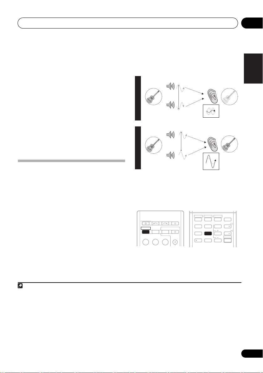
Better sound using Phase Control
This receiver’s Phase Control feature uses
phase correction measures to make sure your
sound source arrives at the listening position in
phase, preventing unwanted distortion and/or
coloring of the sound (see illustration below).
During multichannel playback, LFE (Low-
Frequency Effects) signals as well as lowfrequency signals in each channel are
assigned to the subwoofer or other the
subwoofer and the most appropriate speaker.
At least in theory, however, this type of
processing involves a group delay that varies
with frequency, resulting in phase distortion
where the low-frequency sound is delayed or
muffled by the conflict with other ch
ann
els.
With the Phase Control mode switched on,
this receiver can reproduce powerful bass
sound without deteriorating the quality of the
original sound (see illustration below).
P
H
A
S
E
C
O
N
T
R
O
L
O
F
F
P
H
A
S
E
C
O
N
T
R
O
L
O
N
Sound
source
Sound
source
Front speaker
Subwoofer
Front speaker
Subwoofer
Listening
position
Listening
position
?
Phase Control technology provides coherent
sound reproduction through the use of phase
matching
1
for an optimal sound image at your
listening position. The default setting is on
and we recommend leaving Phase Control
switched on for all sound sources.
HDD
DVD
VCR
RECEIVER
RECEIVER
RECEIVER
BD TV
INPUT SELECT
ZONE 2
ON/OFF
TV CONTROL
INPUT
DVR
SOURCE
1
S.RETRIEVER
4
SB CH
7
+
10
SPEAKERS
EQ
PHASE
2
5
8
0
3
CH SELECT
6
9
ENTER
DISPLAY
SLEEP
CH
MIDNIGHT
CH
SHIFT
• Press RECEIVER, then press PHASE to
switch on phase correction.
English
Français
Italiano
Nederlands
Español
Deutsch
1 Phase matching is a very important factor in achieving proper sound reproduction. If two waveforms are ‘in phase’, they crest
and trough together, resulting in increased amplitude, clarity and presence of the sound signal. If a crest of a wave meets a
trough (as shown in the upper section of the diagram above) then the sound will be ‘out of phase’ and an unreliable sound
image will be produced.
• If your subwoofer has a phase control switch, set it to the plus (+) sign (or 0°). However, the effect you can actually feel when
PHASE CONTROL is set to ON on this receiver depends on the type of your subwoofer. Set your subwoofer to maximize the
effect. It is also recommended you try changing the orientation or the place of
• Set the built-in lowpass filter switch of your subwoofer to OFF. If this cannot be done on your subwoofer, set the cutoff
frequency to a higher value.
• If the speaker distance is not properly set, you may not have a maximized PHASE CONTROL effect.
• The PHASE CONTROL mode cannot be set to ON in the following cases:
– When the PURE DIRECT mode is switched on.
– When the MULTI IN input is selected.
y
our subwoofer.
11
En
Page 12
Connecting up03
Note
Chapter 3:
Connecting up
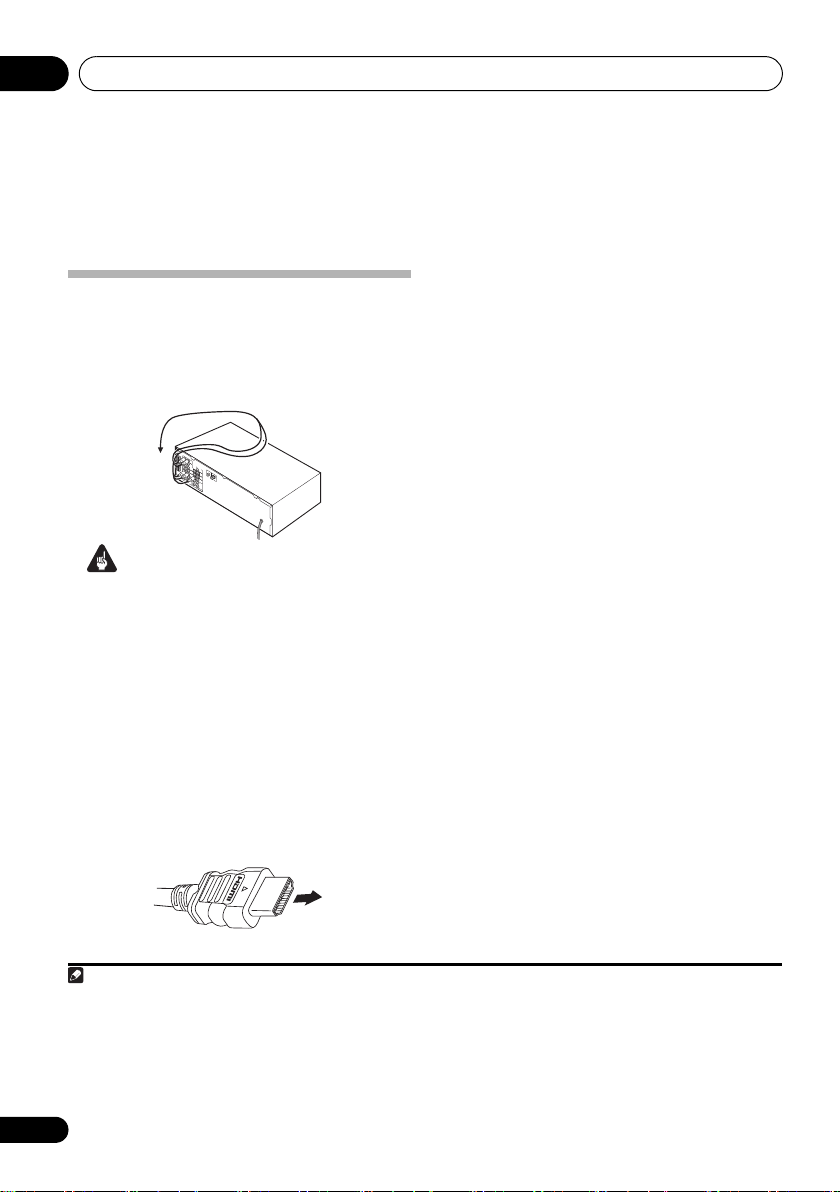
Making cable connections
Make sure not to bend the cables over the top
of this unit (as shown in the illustration). If this
happens, the magnetic field produced by the
transformers in this unit may cause a
humming noise from the speakers.
Important
• Before making or changing connections,
switch off the power and disconnect the
power cord from the AC outlet.
• Before unplugging the power cord, switch
the power into standby.
HDMI cables
The HDMI cables transfers uncompressed digital
video, as well as almost every kind of digital audio
that the connected component is compatible
with, including DVD-video, DVD-Audio, Dolby
Digital Plus, Dolby TrueHD, DTS-HD Master
Audio (see below for limitations), Video CD/Super
VCD, CD, SACD (DSD 2 ch only) and 192 kHz/8
ch (Max. number of channel inputs) PCM.
1
Be careful to connect the terminal in the
proper direction.
About HDMI
HDMI (High Definition Multimedia Interface)
supports both video and audio on a single
digital connection for use with DVD players,
DTV, set-top boxes, and other AV devices. HDMI
was developed to provide the technologies of
High Bandwidth Digital Content Protection
(HDCP) as well as Digital Visual Interface (DVI)
in one specification. HDCP is used to protect
digital content transmitted and received by DVIcompliant displays.
HDMI has the capability to support standard,
enhanced, or high-definition video plus
standard to multi-channel surround-sound
audio. HDMI features include uncompressed
digital video, a bandwidth of up to 2.2 gigabytes
per second (with HDTV signals), one connector
(instead of several cables and connectors), and
communication between the AV source and AV
devices such as DTVs.
This receiver is also compatible with the
DeepColor and x.v.Color feature (x.v.Color is
trademarks of Sony Corporation).
HDMI, the HDMI logo and High-Definition
Multimedia Interface are trademarks or
registered trademarks of HDMI Licensing, LLC.
HDMI cable
1 • Set the HDMI parameter in Setting the Audio options on page 39 to THRU (THROUGH) and set the input signal in Choosing
the input signal on page 41 to HDMI, if you want to hear HDMI audio output from your TV or flat screen TV (no sound will be
heard from this receiver).
• If the video signal does not appear on your TV or flat screen TV, try adjusting the resolution settings on your component or
display. Note that some components (such as video game units) have resolutions that may not be displayed. In this case, use
a (analog) composite connection.
• The signals input from the analog (composite and component) video inputs of this unit will not be output from the HDMI OUT.
• When the video signal from the HDMI is 480i, 480p, 576i or 576p, Multi Ch PCM sound and HD sound cannot be received.
12
En
Page 13
Connecting up 03
Note
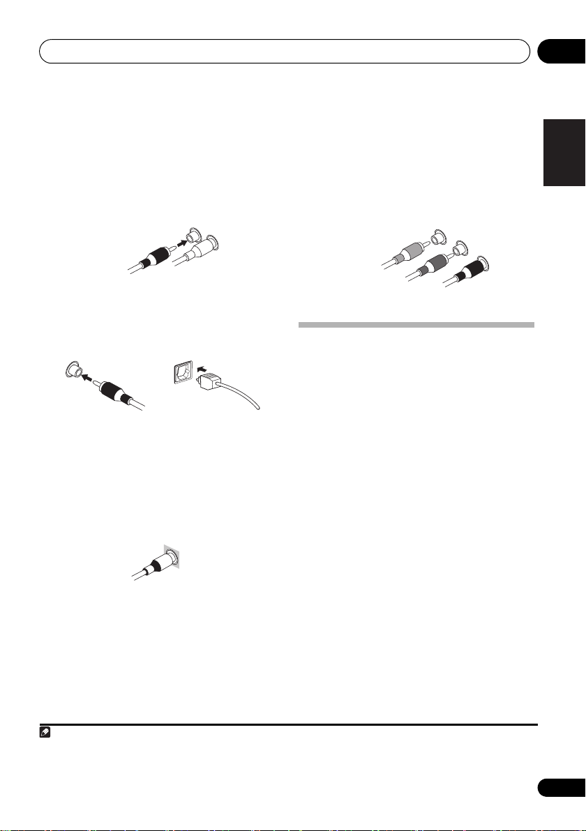
Standard RCA video cable
Analog audio cables
Use stereo RCA phono cables to connect
analog audio components. These cables are
typically red and white, and you should
connect the red plugs to R (right) terminals
and white plugs to L (left) terminals.
Analog audio cables
Right (red)
Left (white)
Digital audio cables
Commercially available coaxial digital audio
cables or optical cables should be used to
connect digital components to this receiver.
Coaxial digital audio cable Optical cable
Video cables
Standard RCA video cables
These cables are the most common type of
video connection and are used to connect to
the composite video terminals. The yellow
plugs distinguish them from cables for audio.
Component video cables
Use component video cables to get the best
possible color reproduction of your video
source. The color signal of the TV is divided
into the luminance (Y) signal and the color (P
and P
R) signals and then output. In this way,
interference between the signals is avoided.
Component video cables
Green (Y)
B)
Blue (P
1
About video outputs connection
Red (P
R)
This receiver is not loaded with a video
converter. When you use component video
cables or HDMI cables for connecting to the
input device, the same cables should be used
for connecting to the TV.
English
B
Français
Italiano
Nederlands
Español
1 • When connecting optical cables, be careful when inserting the plug not to damage the shutter protecting the optical socket.
• When storing optical cable, coil loosely. The cable may be damaged if bent around sharp corners.
• You can also use a standard RCA video cable for coaxial digital connections.
Deutsch
13
En
Page 14
Connecting up03
G
T
O
B
Note
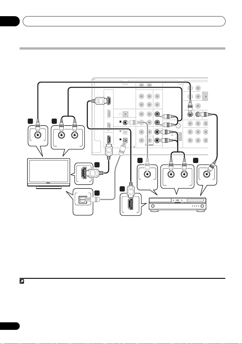
Connecting a TV and Blu-ray Disc player or DVD player
This page shows you how to connect your BD/DVD player and TV to the r eceiver .
This receiver
R AUX
2 4
VIDEO IN
RL
ANALOG AUDIO OUT
HDMI
HDMI
BD/DVD
IN
TV/SAT
IN
DVR/VCR
IN
OUT
OUT
L
IN
IN IN
CD-R/TAPE CD
OUT
DVR/VCR TV/SAT
OUT
IR
IN
ASSIGNABLE
COAXIAL
COAXIAL
IN 1
IN 1
(CD)
(CD)
OPTICAL
IN 2
(AUX)
IN 1
IN 1
(CD-R/TAPE)
(CD-R/TAPE)
ASSIGNABLE ASSI
1-2
AUDIODIGITAL
IN
TV/SAT
FRONT
CENTERSURROUND
BD/DVD IN
BD/DVD IN
SUBWOOFER
BD/DVD MULTI CH IN
L
R
IN
IN
L
L
R
R
FM
UNBAL
75
L
L
AM
LOOP
R
R
MONITOR OUT BD/DVD IN
MONITOR OUT BD/DVD IN TV/SA
ANTENNA
Ω
SURROUND
ZONE2
OUT
DVR/VCR
OUT
R
COMPONENT VIDEO
BACK
L (Single)R
PRE
SU
L R
IN
YPBP
2
HDMI IN
TV
OPTICAL
DIGITAL
AUDIO OUT
4
1
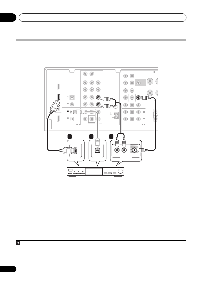
1 Connect the HDMI output on your
BD/DVD player to the HDMI BD/DVD IN input
on this receiver.
Use an HDMI cable for the connection. If an
HDMI output is not on your DVD player, use a
digital audio cable to connect the coaxial or
optional output and this unit.
1 In this case, you’ll need to tell the receiver which digital input you connected the player to (see Choosing the input signal on
page 41).
2 • When you use an HDMI cable for connection in steps 1 and 2, you can enjoy the home theater in multichannel playback
without following steps 3 and 4.
• The OSD will not appear if you have connected using the HDMI output to your TV. Use component or composite connections
for system setup.
3See Using the component video jacks on page 19 if you want to use the component video outputs to connect this receiver to
your TV.
1
1
COAXIAL
DIGITAL
AUDIO OUT
HDMI OUT
BD/DVD player
2 Connect the HDMI OUT on this receiver to
an HDMI input on your TV.
RL
ANALOG AUDIO OUT
2
If an HDMI input is not on your TV, connect the
MONITOR OUT video jack on this receiver to a
video input on your TV.
Use a standard RCA video cable to connect to
the composite video jack.
3
14
En
3
VIDEO OUT
Page 15
Connecting up 03
Note
)
)
T
O
O
3 Connect the composite video output and
the stereo analog audio outputs
1
on your
BD/DVD player to the BD/DVD inputs on this
receiver.
Use a standard RCA video cable
2
and a stereo
RCA phono cable for the connection.
•If your BD/DVD player has multichannel
analog outputs, see Connecting the
multichannel analog outputs below for how
to connect it.
4 Connect the analog audio outputs from
your TV to the TV/SAT inputs on this receiver.
This will allow you to play the sound from the
TV’s built-in tuner. Use a stereo RCA phono
cable to do this.
•If your TV has a built-in digital decoder, you
can also connect an optical digital audio
output from your TV to the DIGITAL
OPTICAL IN 2 (AUX) input on this receiver.
Use an optical cable for the connection.
3
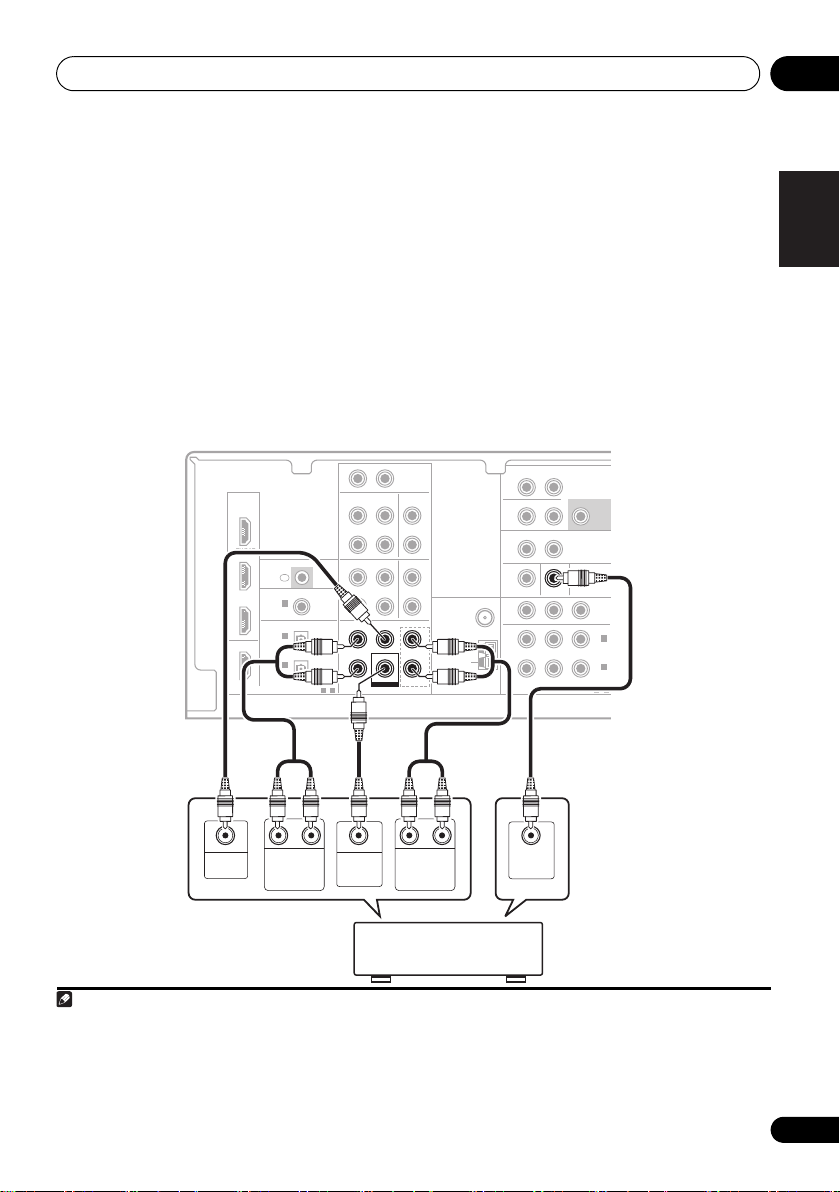
Connecting the multichannel analog outputs
For DVD Audio and SACD playback, your BD/DVD player may have 5.1 channel analog outputs. In this
case, you can connect them to the multichannel analog outputs to the multichannel inputs of this
receiver as shown below.
4
This receiver
HDMI
BD/DVD
IN
TV/SAT
IN
DVR/VCR
IN
OUT
(CD-R/TAPE)
COAXIAL
IN 1
OPTICAL
IN 2
(AUX)
IN 1
R AUX
L
IN
IN IN
CD-R/TAPE CD
OUT
DVR/VCR TV/SAT
OUT
IR
IN
ASSIGNABLE
(CD)
ASSIGNABLE
1-2
AUDIODIGITAL
IN
CENTERSURROUND
FRONT
FRONT
CENTERSURROUND
BD/DVD IN
SUBWOOFER
SUBWOOFER
BD/DVD MULTI CH IN
BD/DVD MULTI CH IN
L
R
IN
L
R
FM
UNBAL
75
L
L
AM
LOOP
R
R
ZONE2
OUT
OUT
MONITOR OUT BD/DVD IN TV/SAT IN
ANTENNA
Ω
COMPONENT VIDEO
SURROUND
L (Single)R
BACK
L R
IN
DVR/VCR VIDE
BD/DVD IN
R
PRE OUT
SUBWOOFER
YPBP
ASSIGNABLE
AUDI
PRE OU
OUT
IN 2
(TV/SAT
IN 1
(BD/DVD
1-2
English
Français
Italiano
Nederlands
Español
CENTER
OUTPUT
RL
SURROUND
OUTPUT
WOOFER
OUTPUT
RL
SUB-
FRONT
OUTPUT
DVD/multi-channel decoder
VIDEO
OUTPUT
with multi-channel analog
output jacks
1 This connection will allow you to make analog recordings from your BD/DVD player.
2If your player also has a component video output, you can connect this too. See Using the component video jacks on page 19
for more on this.
3 In this case, you’ll need to tell the receiver which digital input you connected the TV to (see Choosing the input signal on page 41).
4 • The multichannel input can only be used when MULTI IN is selected (see page 41).
• You can assign COMPONENT VIDEO IN 1 or IN 2 to the multi channel input. (For more on this, see The Input Assign menu
on page 45.)
Deutsch
15
En
Page 16
Connecting up03
Note
Connecting a satellite receiver or other digital set-top box
Satellite and cable receivers, and terrestrial digital TV tuners are all examples of so-called ‘set-top
boxes’.
This receiver
R AUX
HDMI
HDMI
BD/DVD
IN
TV/SAT
TV/SAT
IN
IN
IR
IN
ASSIGNABLE
COAXIAL
DVR/VCR
IN
IN 1
(CD)
OPTICAL
IN 2
IN 2
(AUX)
(AUX)
OUT
IN 1
(CD-R/TAPE)
ASSIGNABLE
1-2
AUDIODIGITAL
1 1 2
IN
CD-R/TAPE CD
OUT
DVR/VCR TV/SAT
OUT
BD/DVD MULTI CH IN
CENTERSURROUND
SUBWOOFER
L
IN IN
IN
TV/SAT
FRONT
BD/DVD IN
L
R
IN
IN
L
L
R
R
FM
UNBAL
75
L
AM
LOOP
R
ZONE2
OUT
MONITOR OUT BD/DVD IN TV/SAT IN
ANTENNA
Ω
COMPONENT VIDEO
SURROUND
L (Single)R
BACK
L R
IN
DVR/VCR VIDEO
OUT
R
PRE OUT
SUBWOOFER
TV/SAT IN
YPBP
ASSIGNABLE
AUDIO
PRE OUT
OUT
IN 2
(TV/SAT)
IN 1
(BD/DVD)
1-2
SPEAKERS A
R
SPEAKERS B
FRONT
R
HDMI OUT
OPTICAL
DIGITAL OUT
AUDIO/VIDEO OUT
VIDEOAUDIORL
STB
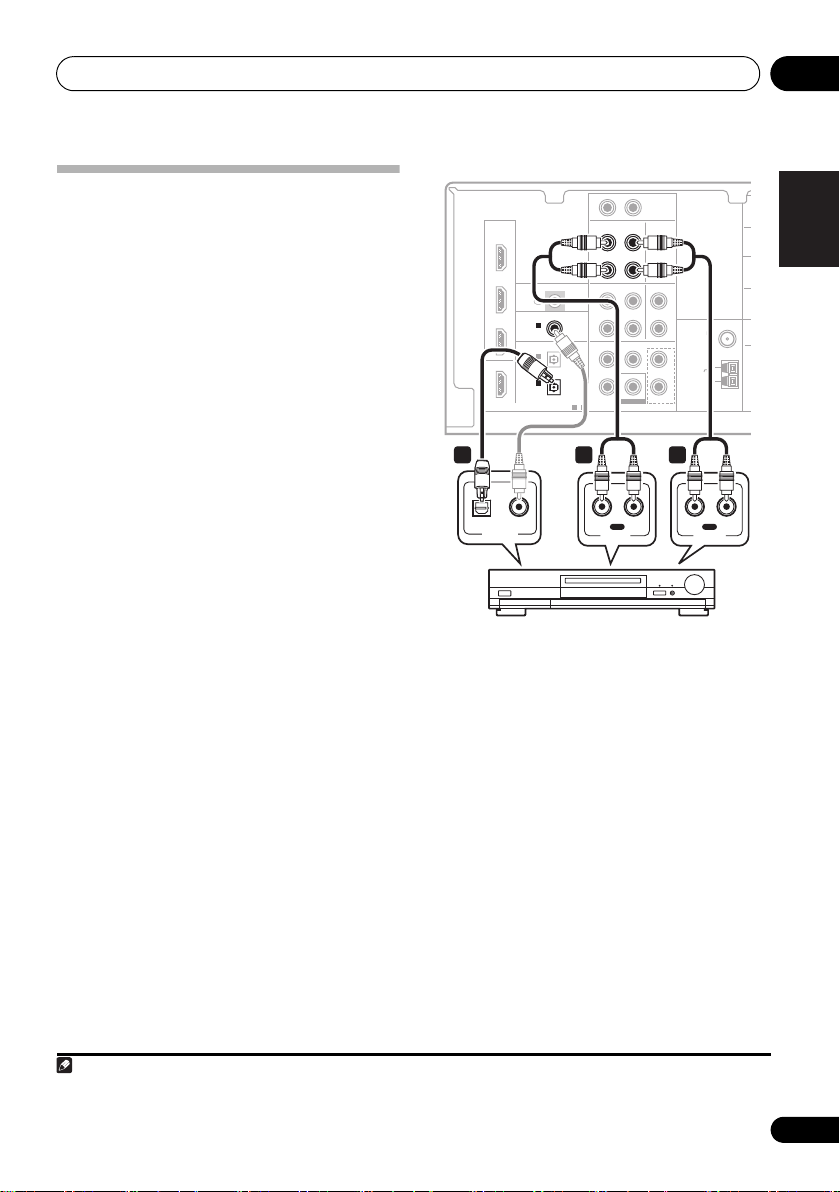
1 If your set-top box has an HDMI output,
connect it to an HDMI TV/SAT IN on this
reciever.
If your set-top box does not have an HDMI
output but a digital output, connect it to a
digital input on this receiver.
The example shows an optical connection to
the DIGITAL OPTICAL IN 2 (AUX) input.
1 In this case, you’ll need to tell the receiver which input you connected the set-top box to (see Choosing the input signal on
page 41).
2 If you’ve already connected your TV to the TV/SAT inputs, simply choose another input. However, to receive a signal, you’ll
need to press the input select button for the input you connected the set-top box to.
3See Using the component video jacks on page 19 if your set-top box also has a component video output.
1
2 Connect a set of audio/video outputs on
the set-top box component to the TV/SAT
AUDIO and VIDEO inputs on this receiver.
Use a stereo RCA phono cable for the audio
connection and a standard RCA video cable for
the video connection.
3
16
En
2
Page 17
Connecting up 03
Note
C
O
U
O
Connecting other audio components
The number and kind of connections depends
on the kind of component you’re connecting.
Follow the steps below to connect a CD-R, MD,
DAT, tape recorder or other audio component.
1 If your component has a digital output,
connect this to a digital input on the receiver
as shown.
The example shows an optical connection to
the DIGITAL OPTICAL IN 1 (CD-R/TAPE)
input.
2 If necessary, connect the analog audio
outputs of the component to a set of spare
audio inputs on this receiver.
You’ll need to make this connection for
components without a digital output, or if you
want to record from a digital component. Use a
stereo RCA phono cable as shown.
3 If you’re connecting a recorder, connect
the analog audio outputs to the analog audio
inputs on the recorder.
The example shows an analog connection to
the CD-R/TAPE analog output jack using a
stereo RCA phono cable.
This receiver
R AUX
L
IN
HDMI
BD/DVD
IN
1
TV/SAT
IN
DVR/VCR
IN
OUT
DIGITAL
COAXIAL
COAXIAL
IN 1
IN 1
(CD)
(CD)
OPTICAL
OPTICAL
IN 2
(AUX)
IN 1
IN 1
(CD-R/TAPE)
(CD-R/TAPE)
IN
IR
ASSIGNABLE
ASSIGNABLE
1-2
CD-R/TAPE
CD-R/TAPE CD
OUT
OUT
DVR/VCR TV/SAT
OUT
AUDIODIGITAL
BD/DVD MULTI CH IN
AUDIO
CENTERSURROUND
SUBWOOFER
IN IN
IN
IN
FRONT
BD/DVD IN
L
L
R
R
IN
L
ANTENNA
R
FM
UNBAL
75
Ω
L
AM
LOOP
R
Z
O
M
English
Français
1 23
IN
OPTICAL COAXIAL
DIGITAL OUT
RL
REC
AUDIO IN
CD-R, MD, DAT, Tape recorder, etc.
OUT
RL
PLAY
AUDIO OUT
Italiano
Nederlands
Español
1 Note that you must connect digital components to analog audio jacks if you want to record to/from digital components (like
an MD) to/from analog components.
Deutsch
17
En
Page 18
Connecting up03
E
K
Note
Connecting an HDD/DVD recorder, VCR and other video sources
This receiver has audio/video inputs and outputs suitable for connecting analog or digital video
recorders, including VCRs and HDD/DVD recorders.
This receiver
R AUX
HDMI
HDMI
BD/DVD
IN
TV/SAT
IN
DVR/VCR
IN
OUT
DIGITAL
COAXIAL
IN 1
(CD)
OPTICAL
OPTICAL
IN 2
IN 2
(AUX)
(AUX)
IN 1
(CD-R/TAPE)
IN
IR
ASSIGNABLE
ASSIGNABLE
1-2
CD-R/TAPE CD
OUT
DVR/VCR
DVR/VCR TV/SAT
OUT
OUT
AUDIODIGITAL
BD/DVD MULTI CH IN
IN
CENTERSURROUND
SUBWOOFER
L
IN IN
IN
IN
FRONT
BD/DVD IN
L
R
IN
L
L
R
R
FM
UNBAL
75
L
AM
LOOP
R
ZONE2
OUT
OUT
OUT
MONITOR OUT BD/DVD IN TV/SAT IN
ANTENNA
Ω
COMPONENT VIDEO
SURROUND
L (Single)R
BACK
L R
IN
IN
DVR/VCR VIDEO
DVR/VCR VIDEO
R
PRE OUT
SUBWOOFER
YPBP
ASSIGNABLE
AUDIO
PRE OUT
OUT
IN 2
(TV/SAT)
IN 1
(BD/DVD)
1-2
SPEAK
R
SPEA
1
HDMI OUT
1
OPTICAL
DIGITAL OUT
3 2
IN
RL
REC
VIDEO IN
AUDIO IN
OUT
RL
PLAY
AUDIO OUT
VIDEO OUT
DVR, VCR, LD player, etc.
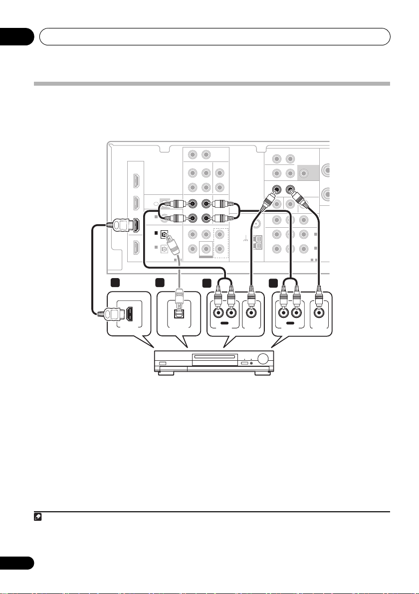
1 If your video component has an HDMI
output, connect it to an HDMI DVR/VCR IN
on this receiver.
If your video component does not have an
HDMI audio output but a digital audio output,
connect it to a digital input on this receiver.
The example shows a recorder connected to
the DIGITAL OPTICAL IN 2 (AUX) input.
1
2 Connect a set of audio/video outputs on
the recorder to the DVR/VCR AUDIO and
VIDEO inputs on this receiver.
Use a stereo RCA phono cable for the audio
connection and a standard RCA video cable for
the video connection.
2
3 Connect a set of audio/video inputs on
the recorder to the DVR/VCR AUDIO and
VIDEO outputs on this receiver.
Use a stereo RCA phono cable for the audio
connection and a standard RCA video cable for
the video connection.
1 In this case, you’ll need to tell the receiver which digital input you connected the component to (see Choosing the input signal
on page 41).
2If your video component also has a component video output, you can connect this too. See Using the component video jacks
on page 19 for more on this.
18
En
Page 19
Connecting up 03
E
P
Using the component video jacks
Component video should deliver superior picture quality when compared to composite video. A
further advantage (if your source and TV are both compatible) is progressive-scan video, which
delivers a very stable, flicker-free picture. See the manuals that came with your TV and source
component to check whether they are compatible with progressive-scan video.
This receiver
R AUX
HDMI
BD/DVD
IN
2
P
RYPB
COMPONENT VIDEO IN
TV/SAT
IN
DVR/VCR
IN
OUT
COAXIAL
IN 1
(CD)
OPTICAL
IN 2
(AUX)
IN 1
(CD-R/TAPE)
IN
1
TV
P
RYPB
COMPONENT VIDEO OUT
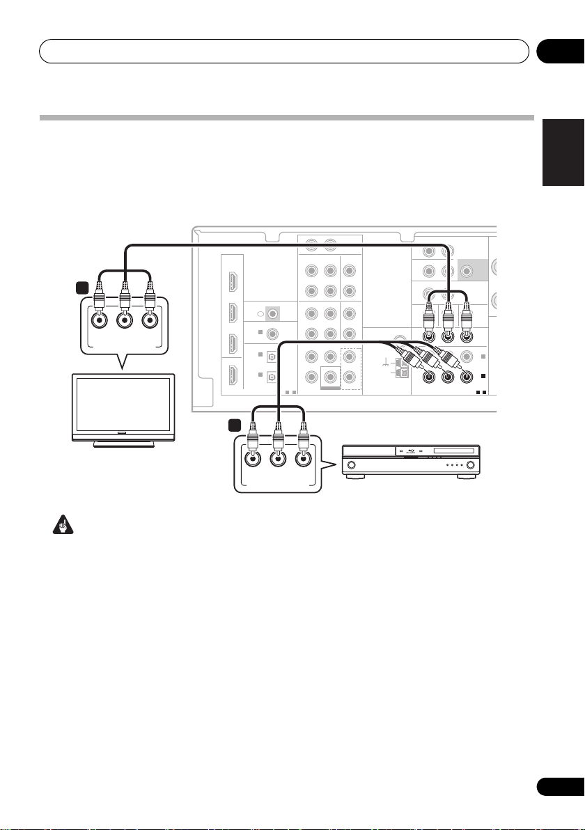
Important
• If you connect any source component to
the receiver using a component video
input, you must also have your TV
connected to this receiver’s COMPONENT
VIDEO OUT jacks.
1 Connect the component video outputs of
your source to a set of component video
inputs on this receiver.
Use a three-way component video cable for the
connection.
L
IN
IN IN
CD-R/TAPE CD
IR
ASSIGNABLE
ASSIGNABLE
1-2
OUT
DVR/VCR TV/SAT
OUT
AUDIODIGITAL
IN
FRONT
CENTERSURROUND
BD/DVD IN
SUBWOOFER
BD/DVD MULTI CH IN
L
R
IN
L
R
FM
UNBAL
75
L
AM
LOOP
R
BD/DVD player
2 If necessary, assign the component video
inputs to the input source you’ve connected.
This only needs to be done if you didn’t
connect according to the following defaults:
• COMPONENT VIDEO IN 1 – BD/DVD
• COMPONENT VIDEO IN 2 – TV/SAT
See The Input Assign menu on page 45 for
more on this.
3 Connect the COMPONENT VIDEO OUT
jacks on this receiver to the component video
inputs on your TV or monitor.
Use a three-way component video cable.
ZONE2
OUT
OUT
MONITOR OUT BD/DVD IN TV/SAT IN
ANTENNA
Ω
COMPONENT VIDEO
COMPONENT VIDEO
SURROUND
L (Single)R
BACK
L R
IN
DVR/VCR VIDEO
YPBP
YPBP
R
R
AUDIO
PRE OUT
SUBWOOFER
PRE OUT
OUT
OUT
(TV/SAT)
IN 1
(BD/DVD)
(BD/DVD)
ASSIGNABLE
ASSIGNABLE
SP
S
IN 2
IN 1
1-2
1-2
English
Français
Italiano
Nederlands
Español
Deutsch
19
En
Page 20
Connecting up03
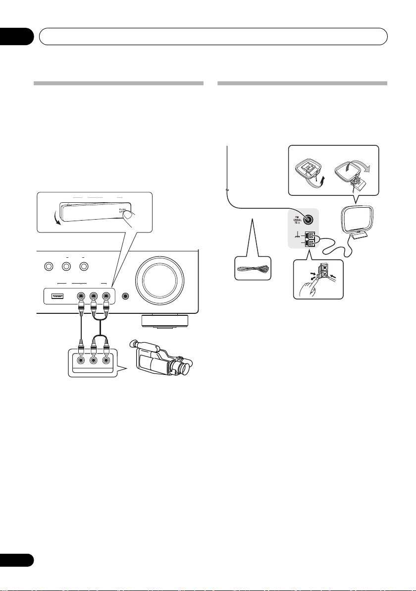
Connecting to the front panel video terminal
Front video connections are accessed via the
front panel using the INPUT SELECTOR or
VIDEO button on the remote control. There are
standard audio/video jacks. Hook them up the
same way you made the rear panel connections.
•Push down on the PUSH OPEN tab to
access the front video connections.
VIDEO INPUT
USB
This receiver
MULTI-ZONE
SPEAKERS
CONTROL
iPod
USB
iPod
ON/OFF
VIDEO INPUT
AUDIO/VIDEO OUTPUT
RLAUDIOVIDEO
MASTER
VOLUME
RLAUDIOVIDEO
MCACC
SETUP MIC
Video camera
(etc.)
LVIDEO
R
Connecting antennas
Connect the AM loop antenna and the FM wire
antenna as shown below. To improve reception
and sound quality, connect external antennas
(see Using external antennas on page 21).
fig. a fig. b
2
3
1
LOOP
ANTENNA
AM
4
1 Push open the tabs, then insert one wire
fully into each terminal, then release the tabs
to secure the AM antenna wires.
2 Fix the AM loop antenna to the attached
stand.
To fix the stand to the antenna, bend in the
direction indicated by the arrow (fig. a) then
clip the loop onto the stand (fig. b).
3 Place the AM antenna on a flat surface
and in a direction giving the best reception.
4 Connect the FM wire antenna in the same
way as the AM loop antenna.
For best results, extend the FM antenna fully
and fix to a wall or door frame. Don’t drape
loosely or leave coiled up.
20
En
Page 21
Connecting up 03
ANTENNA
AM
LOOP
Outdoor
antenna
Indoor antenna
(vinyl-coated wire)
5 m to 6 m
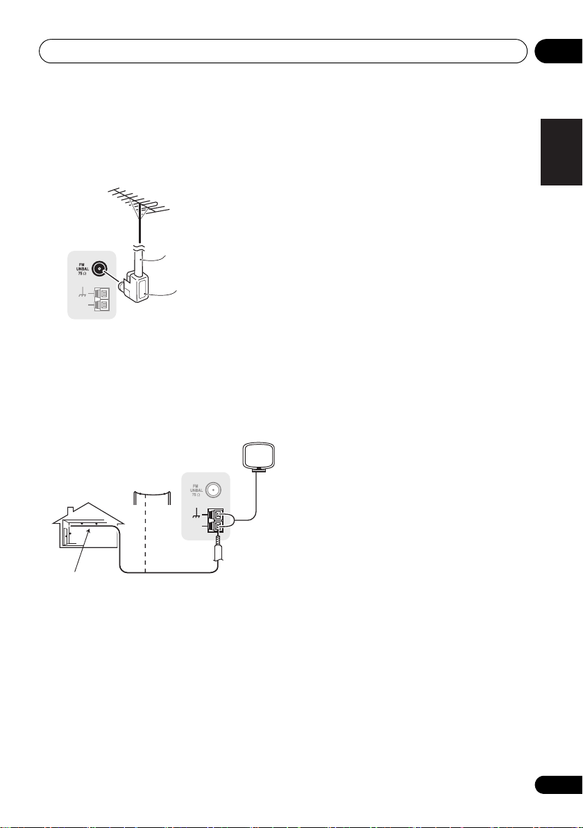
Using external antennas
To improve FM reception
Connect an external FM antenna as shown
below.
ANTENNA
AM
LOOP
To improve AM reception
Connect a 5 m to 6 m length of vinyl-coated
wire to the AM antenna terminal without
disconnecting the supplied AM loop antenna.
For the best possible reception, suspend
horizontally outdoors.
75 Ω coaxial cable
J-shaped
plug
(not supplied)
English
Français
Italiano
Nederlands
Español
Deutsch
21
En
Page 22
Connecting up03
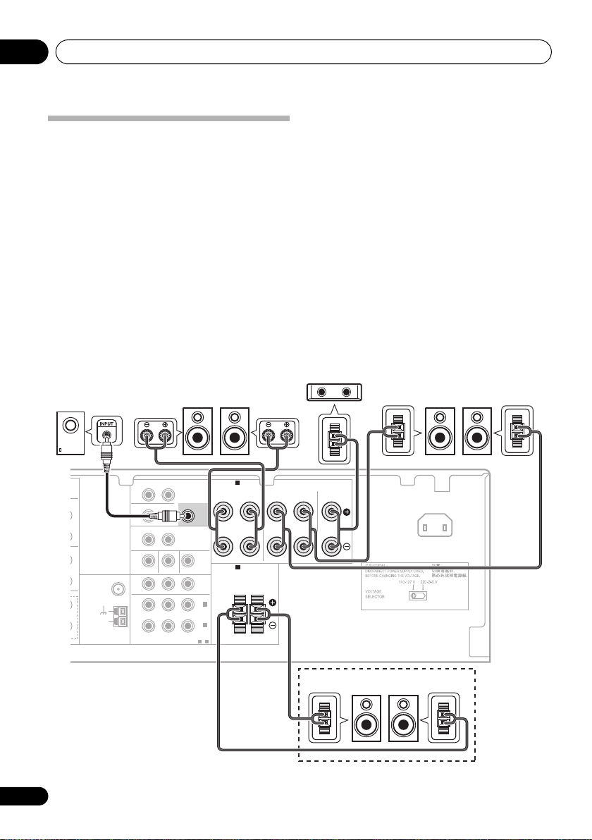
Connecting the speakers
A complete setup of six speakers (including the
subwoofer) is shown here but everyone’s home
setup will vary. Simply connect the speakers
you have in the manner shown below. The
receiver will work with just two stereo speakers
(the front speakers in the diagram) but using at
least three speakers is recommended, and a
complete setup is best for surround sound. If
you’re not using a subwoofer, change the front
speaker setting (see Speaker Setting on
page 43) to LARGE.
Make sure you connect the speaker on the
right to the right terminal and the speaker on
the left to the left terminal.
SW
Powered subwoofer
Front speakers
R
L
You can use the speakers connected to the B
speaker terminals to listen to stereo playback
in another room. Make sure to review Placing
the speakers on page 24 when placing the
speakers in another room. See Switching the
speaker system on page 25 for the listening
options with this setup.
You can use speakers with a normal
impedance between 6 Ω and 16 Ω.
However, note that only the front speakers and
the speaker system B are set to a value
between 12 Ω and 16 Ω if you select SPAB in
Switching the speaker system on page 25.
Be sure to complete all connections before
connecting this unit to the AC power source.
Center speaker
C
Surround speakers
SL SR
22
En
SURROUND
BACK
IN
L
R
IN
L
R
L
R
IN
FM
UNBAL
75
AM
LOOP
ANTENNA
Ω
ZONE2
OUT
DVR/VCR VIDEO
OUT
MONITOR OUT BD/DVD IN TV/SAT IN
R
COMPONENT VIDEO
L (Single)R
L R
IN
PRE OUT
SUBWOOFER
SUBWOOFER
YPBP
ASSIGNABLE
AUDIO
PRE OUT
PRE OUT
OUT
IN 2
(TV/SAT)
IN 1
(BD/DVD)
1-2
SPEAKERS A
SPEAKERS A
SPEAKERS B
SPEAKERS B
FRONT
FRONT
RL
RL
RL
RL
SURROUND CENTER
SURROUND CENTER
R L
R L
AC IN
Speaker system B
LR
Page 23
Connecting up 03
O
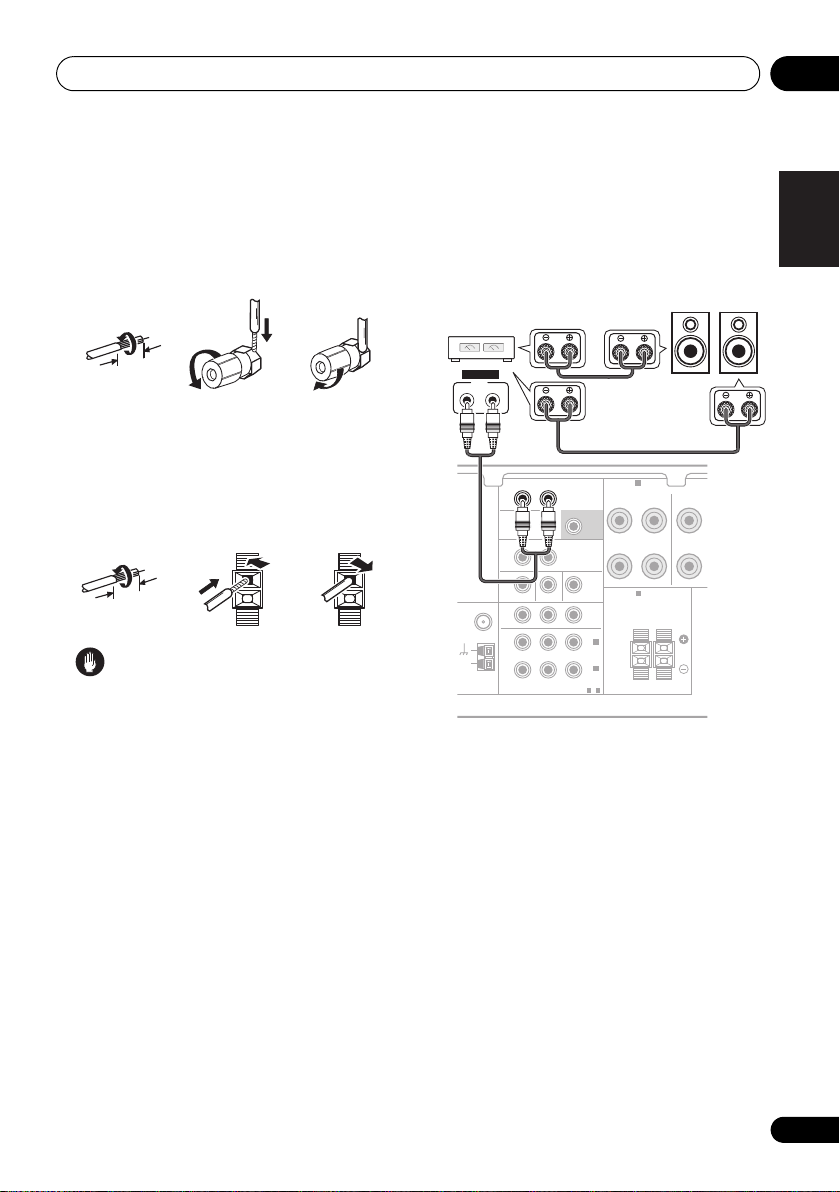
Bare wire connections
A-Speaker terminals:
1 Twist exposed wire strands together.
2 Loosen terminal and insert exposed wire.
3 Tighten terminal.
123
10 mm
B-Speaker terminals:
1 Twist exposed wire strands together.
2 Push open the tabs and insert exposed
wire.
3 Release the tabs.
12
3
10 mm
Caution
•These speaker terminals carry
HAZARDOUS LIVE voltage. To prevent
the risk of electric shock when connecting
or disconnecting the speaker cables,
disconnect the power cord before touching
any uninsulated parts.
•Make sure that all the bare speaker wir e is
twisted together and inserted fully into the
speaker terminal. If any of the bare speaker
wire touches the back panel it may cause
the power to cut off as a safety measure.
Use the PRE OUT outputs to connect the surround back speakers
Connect the PRE OUT outputs of the unit and
additional amplifier to add a surround back
speaker.
Surround back
channel amplifier
ANALOG
INPUT
LR
SURROUND
L (Single)R
BACK
ZONE2
OUT
L R
IN
DVR/VCR VIDEO
OUT
75
LOOP
FM
NBAL
AM
ANTENNA
Ω
MONITOR OUT BD/DVD IN TV/SAT IN
R
COMPONENT VIDEO
YPBP
• You can use the additional amplifier on the
surround back channel pre-outs for a
single speaker as well. In this case plug
the amplifier into the left (L (Single))
terminal only.
Surround Back speakers
SPEAKERS A
AUDIO
SUBWOOFER
PRE OUT
OUT
IN 2
(TV/SAT)
IN 1
(BD/DVD)
ASSIGNABLE
1-2
FRONT
RL
SPEAKERS B
RL
PRE OUT
SBL SBR
SURR
R
English
Français
Italiano
Nederlands
Español
Deutsch
23
En
Page 24
Connecting up03
Note
Center
Front left
Front right
Surround
left
Surround
right
Subwoofer
120°
120°
Center
Front left
Front right
Surround
left
Surround
right
Subwoofer
120°
120°
Surround Back
Center
Front left Front right
Surround
left
Surround
right
Subwoofer
90°
90°
Surround back
left
Surround back
right
60°
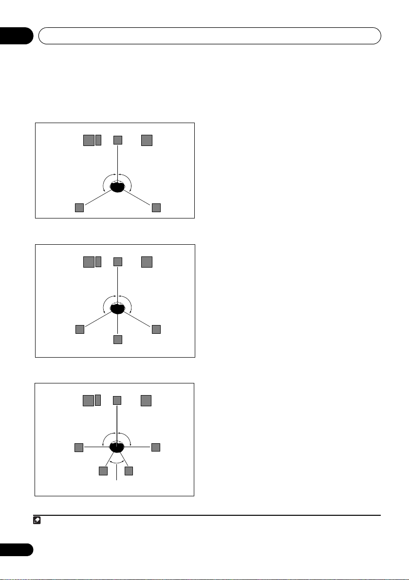
Placing the speakers
To achieve the best possible surround sound,
install your speakers as shown below.
5.1 channel surround system:
Where you put your speakers in the room has a
big effect on the quality of the sound. The
following guidelines should help you to get the
best sound from your system.
• The subwoofer can be placed on the floor.
Ideally, the other speakers should be at
about ear-level when you’re listening to
them. Putting the speakers on the floor
(except the subwoofer), or mounting them
very high on a wall is not recommended.
•For the best stereo effect, place the front
speakers 2 m to 3 m apart, at equal
distance from the TV.
•When placing speakers near the TV, we
6.1 channel surround system:
1
recommend using magnetically shielded
speakers to prevent possible interferen
ch as discoloration of the picture when
su
the TV is switched on. If you do not have
magnetically shielded speakers and notice
discoloration of the TV picture, move the
speakers farther away from the TV.
•If you’re using a center speaker, place the
front speakers at a wider angle. If not, place
them at a narrower angle.
•Place the center speaker above or below
the TV so that the sound of the center
channel is localized at the TV screen. Also,
make sure the center speaker does not
7.1 channel surround system:
1
cross the line formed by the leading edge
of the front left and right speakers.
• It is best to angle the speakers t
listening position. The angle depends on
the size of the room. Use less of an angle
for bigger rooms.
•Surround and surround back speakers
should be positioned 60 cm to 90 cm higher
than your ears and titled slight downward.
Make sure the speakers don’t face each
1 • This layout is available only when the additional amplifier is connected to the unit and the surround back speakers are
connected to the amplifier. For details, see Use the PRE OUT outputs to connect the surround back speakers on page 23.
24
En
other. For DVD-Audio, the speakers should
be more directly behind the listener than for
home theater playback.
owards t
ce,
he
Page 25

Connecting up 03
Note
SPEAKERS
CONTROL
MULTI-ZONE
ON/OFF
SPEAKERS
• If the surround speakers cannot be set
directly to the side of the listening position
with a 7.1-channel system, the surround
effect can be enhanced by turning off the
UP Mix function (see Setting the Up Mix
function on page 38).
• Try not to place the surround speakers
farther away from the listening position
than the front and center speakers. Doing
so can weaken the surround sound effect.
Caution
• Make sure that all speakers are securely
installed. This not only improves sound
quality, but also reduces the risk of
damage or injury resulting from speakers
being knocked over or falling in the event of
external shocks such as earthquakes.
Switching the speaker system
Three speaker system settings are possible
using the SPEAKERS button.
• Use the SPEAKERS button on the front
panel to select a speaker system setting.
Press repeatedly to choose a speaker system
option:
• SPA – Sound is output from the speakers
connected to the A speaker terminals and
SURROUND BACK PRE OUT
(multichannel playback is possible).
1
• SPB – Sound is output from the two
speakers connected to speaker system B
(only stereo playback is possible).
• SPAB – Sound is output from speaker
system A, the two speakers in speaker
system B, and the subwoofer.
Multichannel sources are downmixed only
when the STEREO or A.L.C mode is
selected for stereo output from speaker
2
systems A and B.
• SP – No sound is output from the
speakers but from the headphone jack.
Connecting an IR receiver
If you keep your stereo components in a
closed cabinet or shelving unit, or you wish to
use the sub zone remote control in another
zone, you can use an optional IR receiver
(such as a Niles or Xantech unit) to control
your system instead of the remote sensor on
the front panel of this receiver.
1 Connect the IR receiver sensor to the
IR IN
jack on the rear of this receiver.
For more information on connecting the IR
receiver, see the Installation Instructions for
the IR Receiver.
3
English
Français
Italiano
Nederlands
Español
Deutsch
1 The subwoofer output depends on the settings you made in Speaker Setting on page 43. However, if SPB is selected above,
no sound is heard from the subwoofer (the LFE channel is not downmixed).
2 You can use speakers with a normal impedance between 6 Ω and 16 Ω. However, be aware that only the front speakers and
the speaker system B are set to a value between 12 Ω and 16 Ω when you select SPAB.
3 • Remote operation may not be possible if direct light from a strong fluorescent lamp is shining on the IR receiver remote
sensor window.
• Note that other manufacturers may not use the IR terminology. Refer to the manual that came with your component to check
for IR compatibility.
• If using two remote controls (at the same time), the IR receiver’s remote sensor takes priority over the remote sensor on the
front panel.
25
En
Page 26

Connecting up03
Plugging in the receiver
Only plug in after you have connected all your
components to this receiver, including the
speakers.
Caution
• Handle the power cord by the plug part. Do
not pull out the plug by tugging the cord,
and never touch the power cord when your
hands are wet, as this could cause a short
circuit or electric shock. Do not place the
unit, a piece of furniture, or other object on
the power cord or pinch the cord in any
other way. Never make a knot in the cord or
tie it with other cables. The power cords
shoul
be routed so that they are not likely
d
to be stepped on. A damaged power cord
can cause a fire or give you an electric
shock. Check the power cord once in a
while. If you find it damaged, ask your
nearest Pioneer authorized independent
service company for a replacement.
• Do not use any power cord other than the
one supplied with this unit.
• Do not use the supplied power cord for any
purpose other than that described below.
•The receiver should be disconnected by
removing the mains plug from the wall
socket when not in regular use,
on vacation.
1 Plug the supplied power cord into the
IN
socket on the back of the receiver.
2 Plug the other end into a power outlet.
e.g., when
AC
26
En
Page 27
Controls and displays 04
Chapter 4:
Controls and displays
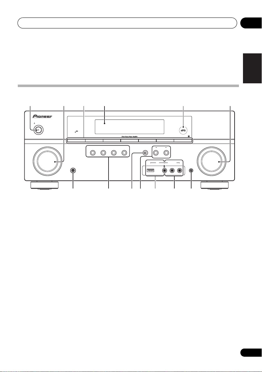
Front panel
1 23 64 5
STANDBY/ON
INPUT
SELECTOR
1
STANDBY/ON
2
INPUT SELECTOR
Selects an input source.
3 Tuner control buttons
BAND
Switches between AM, FM ST (stereo) and
FM MONO radio bands (page 49).
TUNE +/–
Used to find radio frequencies (page 49).
TUNER EDIT
Use with TUNE +/–, PRESET +/– and
ENTER to memorize and name stations for
recall (page 49, 50).
PRESET +/–
Use to select preset radio stations
(page 50).
4 Character display
See Display on page 29.
PHASE
CONTROL
–
STEREO/
+
TUNE
ADVANCED
SURROUND
STANDARD
SURROUND
A.L.C.
PRESET
TUNER EDIT ENTER
SPEAKERS
TUNE
BAND
AUTO SURROUND/
STREAM DIRECT
PHONES
7 8 10 13129 11
5
MCACC
dial
Lights when Acoustic Calibration EQ (page 3 7) is
on (Acoustic Calibration EQ is automatically set
to on after the Auto MCACC Setup (page 9)).
6
MASTER VOLUME
7
PHONES
Use to connect headphones (page 41).
8 Listening mode buttons
AUTO SURROUND/STREAM DIRECT
Switches between Auto surround mode
(Auto playback on page 34) and Stream
Direct playback. Stream Direct playback
bypasses the tone controls for the most
accurate reproduction of a source
(page 37).
STEREO/A.L.C.
Switches between stereo playback, Auto
level control stereo mode (page 36) and
Front Stage Surround Advance modes
(page 36).
–
CONTROL
iPod
USB
+
PRESET
MULTI-ZONE
ON/OFF
VIDEO INPUT
indicator
jack
AUDIO/VIDEO MULTI- CHANNEL RECEIVER
RLAUDIOVIDEO
MCACC
SETUP MIC
dial
VSX–819H
MASTER
VOLUME
English
Français
Italiano
Nederlands
Español
Deutsch
27
En
Page 28
Controls and displays04
BAND
PHONES
INPUT
SELECTOR
STANDBY/ON
PHASE
CONTROL
AUTO SURROUND/
STREAM DIRECT
STEREO/
A.L.C.
ADVANCED
SURROUND
STANDARD
SURROUND
MASTER
VOLUME
SPEAKERS
CONTROL
MULTI-ZONE
ON/OFF
PORTABLE
TUNER
EDIT ENTER
AUDIO
/
VIDEO MULTI-
CHANNEL
RECEIVER
VSX
–
519V
TUNE
–
TUNE
+
PRESET
–
PRESET
+
30
30
7 m
ADVANCED SURROUND
Switches between the various surround
modes (page 35).
STANDARD SURROUND
Press for Standard decoding and to switch
between the various 2 Pro Logic II, 2 P ro
Logic IIx and NEO:6 options (page 34).
9 SPEAKERS
Use to change the speaker system (page 25).
10 MULTI ZONE controls
If you’ve made MULTI-ZONE connections (see
MULTI-ZONE listening on page 47) use these
controls to control the sub zone from the main
zone (see Using the MULTI-ZONE controls on
page 48).
11
iPod
/USB terminal
Use to connect your Apple iPod or USB mass
storage device as an audio source (page 61
and 64).
12
AUDIO/VIDEO
input
See Connecting to the front panel video terminal
on page 20.
13 MCACC SETUP MIC jack
Use to connect a microphone when
performing Auto MCACC setup.
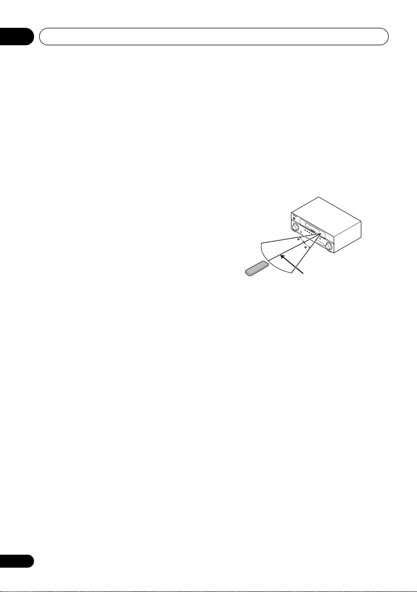
Operating range of remote control
The remote control may not work properly if:
•There are obstacles between the remote
control and the receiver’s remote sensor.
•Direct sunlight or fluorescent light is
shining onto the remote sensor.
•The receiver is located near a device that is
emitting infrared rays.
•The receiver is operated simultaneously
with another infrared remote control unit.
28
En
Page 29
Controls and displays 04
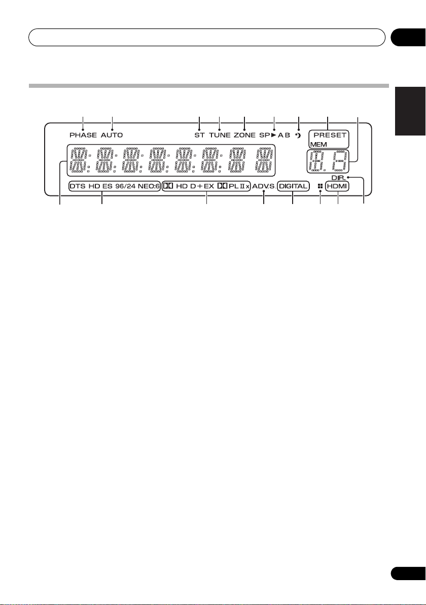
Display
1 2 3 4 5 6 7 8
10
1PHASE
Lights when the Phase Control is switched on
(page 11).
2AUTO
Lights when the Auto Surround feature is
switched on (see Auto playback on page 34).
3ST
Lights when a stereo FM broadcast is being
received in auto stereo mode.
4TUNE
Lights when a normal broadcast channel is
being received.
5ZONE
Lights when the MULTI-ZONE feature is active
(page 47).
6 Speaker indicators
Lights to indicate the current speaker system,
A and/or B (page 25).
7 Sleep timer indicator
Lights when the receiver is in sleep mode
(page 33).
8 Tuner preset indicators
PRESET
Shows when a preset radio station is
registered or called.
MEM
Blinks when a radio station is registered.
11 12 13 14 14 1615
9
9 PRESET Information or Input signal
indicator
Shows the preset number of the tuner or the
input signal type, etc.
10 Character display
Displays various system infomation.
11 DTS indicators
DTS
Lights when a source with DTS encoded
audio signals is detected.
HD
Lights when a source with DTS-EXPRESS
or DTS-HD encoded audio signals is
detected.
ES
Lights to indicate DTS-ES decoding.
96/24
Lights when a source with DTS 96/24
encoded audio signals is detected.
NEO:6
When one of the NEO:6 modes of the
receiver is on, this lights to indicate
NEO:6 processing (page 34).
12 Dolby Digital indicators
2 D
Lights when a Dolby Digital encoded signal
is detected.
English
Français
Italiano
Nederlands
Español
Deutsch
29
En
Page 30

Controls and displays04
2 D+
Lights when a source with Dolby Digital
Plus encoded audio signals is detected.
2 HD
Lights when a source with Dolby TrueHD
encoded audio signals is detected.
EX
Lights to indicate Dolby Digital EX
decoding.
2PLllx
Lights to indicate 2 Pro Logic II / 2 Pro
Logic IIx decoding (see Listening in
surround sound on page 34 for more on
this).
13 ADV.S.
Lights when one of the Advanced Surround
modes has been selected (see Using the
Advanced surround effects on page 35 for more
on this).
14 SIGNAL SELECT indicators
DIGITAL
Lights when a digital audio signal is
selected.
Blinks when a digital audio signal is not
selected.
HDMI
Lights when an HDMI signal is selected.
Blinks when an HDMI signal is not
selected.
15 UP MIX indicator
Lights when the UP MIX Setting is set to ON
(see page 38). Also, lights when DIMMER is set
to off.
16 DIR.
Lights when the DIRECT or PURE DIRECT
mode is switched on (page 37).
30
En
Page 31

Controls and displays 04
Remote control
1
RECEIVER
RECEIVER
BD TV
CD CD-R
VIDEO MULTI IN
iPod USB
AUTO/
DIRECT
AUDIO
PARAMETER
TOP
MENU
T
E
S
E
R
P
HOME
MENU
SETUP
iPod
CTRL
PTY SEARCH
HDD
1
S.RETRIEVER
4
SB CH
7
+
BASS
10
INPUT SELECT
ZONE 2
ON/OFF
DIMMER
STEREO/
A.L.C.
T
ENTER
T
DVD
PHASE
SPEAKERS
RECEIVER
213
3
4
5
6
7
8
9
10
11
12
N
U
U
N
2
EQ
5
8
0
SIGNAL SEL
STANDARD
TUNER EDIT
E
E
CH SELECT
TV CONTROL
INPUT
DVR
TUNER
AUX
BD MENU
TOOLS
MENU
P
R
E
S
E
T
BAND
RETURN
DTV/TV
TRE
VCR
3
6
9
ENTER
SOURCE
CH
VOL
ADV SURR
MASTER
VOLUME
MUTE
DISPLAY
SLEEP
CH
MIDNIGHT
CH
SHIFT
14
15
16
17
18
1 INPUT SELECT
Use to select the input source.
2
RECEIVER
Switches the receiver between standby and on.
3RECEIVER
Switches the remote to control the receiver
(used to select the white commands above the
number buttons (S.RETRIEVER, etc)). Also use
this button to set up surround sound (page 42)
or Audio parameters (page 39).
4 ZONE 2 ON/OFF
Switches zone 2 of the multi-zone function
between on and off.
5
MULTI CONTROL
buttons
Press to select control of other components
(see
Controlling the rest of your system on
page 52
).
6
DIMMER
Dims or brightens the display. The brightness
can be controlled in four steps.
7
SIGNAL SEL
Use to select an input signal (page 41).
Press BD first to access:
BD MENU
Displays the disc menu of Blu-ray Discs.
8 Listening mode buttons
AUTO/DIRECT
Switches between Auto surround mode
(Auto playback on page 34) and Stream
Direct playback. Stream Direct playback
bypasses the tone controls for the most
accurate reproduction of a source
(page 37).
STEREO/A.L.C.
Switches between stereo playback, Auto
level control stereo mode (page 36) and
Front Stage Surround Advance modes
(page 36).
STANDARD
Press for Standard decoding and to switch
between 2 Pro Logic II options (page 34).
English
Français
Italiano
Nederlands
Español
Deutsch
31
En
Page 32

Controls and displays04
Note
ADV SURR
Switches between the various surround
modes (page 35).
9 System Setup and Component control
buttons
The following button controls can be accessed
after you have selected the corresponding
MULTI CONTROL button (BD, TV, etc.).
Press RECEIVER first to access:
AUDIO PARAMETER
Use to access the Audio options (page 39).
SETUP
Press to access the System Setup menu
(page 42).
RETURN
Confirm and exit the current menu screen.
Press BD or DVR first to access:
TOP MENU
Displays the disc ‘top’ menu of a BD/DVD.
HOME MENU
Displays the HOME MENU screen.
RETURN
Confirm and exit the current menu screen.
MENU
Displays the TOOLS menu screen of Blu-ray
Disc player.
Press TUNER first to access:
TUNER EDIT
Memorizes/names stations for recall
(page 49 and 50).
BAND
Switches between AM, FM ST (stereo) and
FM MONO radio bands (page 49).
Press iPod USB first to access:
iPod CTRL
Switches between the iPod controls and
the receiver controls (page 63).
10 (TUNE /, PRESET /),
ENTER
Use the arrow buttons when setting up your
surround sound system (page 42). Also used to
control BD/DVD menus/options.
Use the TUNE / buttons can be used to
find radio frequencies (page 49) and the
PRESET / buttons can be used to select
preset radio stations (page 50).
11 Component control buttons
The main buttons (
, , etc.) are used to
control a component after you have selected it
using the input source buttons.
The controls above these buttons can be
accessed after you have selected the
corresponding input source button (for
example BD, DVR or TV). These buttons
also function as described below.
Press RECEIVER first to access:
BASS –/+
Use to adjust Bass
1
TRE –/+
Use to adjust Treble
1
Press TV first to access:
DTV/TV
Switches between the DTV and analog TV
input modes for Pioneer flat screen TVs.
1 The tone controls are disabled when the listening mode is set to DIRECT or PURE DIRECT.
32
En
Page 33

Controls and displays 04
12 Number buttons and other component
controls
Use the number buttons to directly select a
radio frequency (page 49) or the tracks on a
CD, DVD, etc. There are other buttons that can
be accessed after the RECEIVER button is
pressed. (For example MIDNIGHT, etc.)
HDD*, DVD*, VCR*
These buttons switch between the hard
disk, DVD and VCR controls for HDD/DVD/
VCR recorders.
S.RETRIEVER
Press to restore CD quality sound to
compressed audio sources (page 37).
EQ
Press to switch on/off Acoustic Calibration
EQ setting (page 37).
CH SELECT
Press repeatedly to select a channel, then
use +/– to adjust the level (page 44).
CH SELECT +/–
Use to adjust the channel level.
SB CH
Use to select the surround back channel
mode (page 37).
PHASE
Press t
o switch on/off Phase Control
11).
(page
SPEAKERS
Use to change the speaker system
(page 25).
MIDNIGHT
Switches to Midnight or Loudness
listening (page 39).
SLEEP
Press to change the amount of time before
the receiver switches into standby (30 min
– 60 min – 90 min – Off). You can check
the remaining sleep time at any time by
pressing SLEEP once.
13 SOURCE
Press to turn on/off other components
connected to the receiver (see page 54 for
more on this).
14 TV CONTROL buttons
These buttons are dedicated to control the TV
assigned to the TV button. Thus if you only have
one TV to hook up to this system assign it to the
TV button. (see page 53 for more on this).
Use to turn on/off the power of the TV.
INPUT
Use to select the TV input signa
CH +/–
Use to select channels.
VOL +/–
Use to adjust the volume on your TV.
15 MASTER VOLUME +/–
Use to set the listening volume.
16 MUTE
Mutes/unmutes the sound.
17 DISPLAY
Switches the display of this unit. The input
name, listening mode or sound volume can be
checked by selecting an input source.
18
SHIFT
Press to access the ‘boxed’ commands (above
the buttons) on the remote. These buttons are
marked with an asterisk (* ) in this section.
This button is also used for operating ZONE 2
(page 48).
l
.
English
Français
Italiano
Nederlands
Español
Deutsch
33
En
Page 34

Listening to your system05
Note
STANDARD
ADV SURR
STEREO/
A.L.C.
AUTO/
DIRECT
AUTO/
DIRECT
Chapter 5:
Listening to your system
Important
• The listening modes and many features
described in this section may not be
available depending on the current source,
settings and status of the receiver.
Auto playback
The simplest, most direct listening option is the
Auto Surround feature. With this, the receiver
automatically detects what kind of source
you’re playing and selects multichannel or
stereo playback as necessary.
• While listening to a source, press
AUTO/DIRECT
2
for auto playback of a
source.
Press repeatedly until AUTO SURROUND
shows briefly in the display (it will then show
the decoding or playback format). Check the
digital format indicators in the display to see
how the source is being processed.
1
Listening in surround sound
Using this receiver, you can listen to any source
in surround sound. However, the options
available will depend on your speaker setup and
the type of source you’re listening to.
The following modes provide basic surround
sound for stereo and multichannel sources.
STEREO/
AUTO/
DIRECT
• While listening to a source, press
STANDARD
.
If the source is Dolby Digital, DTS, or Dolby
Surround encoded, the proper decoding
format will automatically be selected and
shows in the display.
When the surround back speaker is not
connected
With two channel sources, you can select from:
• DOLBY PLII MOVIE – Up to 5.1 channel
sound, especially suited to movie sources
• DOLBY PLII MUSIC
sound, especially suited to music sources
• DOLBY PLII GAME – Up to 5.1 channel
sound, especially suited for video games
• NEO:6 CINEMA – Up to 5.1 channel sound,
especially suited to movie sources
• NEO:6 MUSIC – Up to 5.1 channel sound,
especially suited to music sources
• DOLBY PRO LOGIC – 4.1 channel
surround sound
STANDARD
ADV SURR
STANDARD
A.L.C.
3
– Up to 5.1 channel
4
1 Stereo surround (matrix) formats are decoded accordingly using NEO:6 CINEMA or DOLBY PLIIx MOVIE (see Listening in
surround sound above for more on these decoding formats).
2 For more options using this button, see Using Stream Direct on page 37.
3 When listening to 2-channel sources in DOLBY PLII MUSIC mode, there are three further parameters you can adjust:
C.WIDTH, DIMEN., and PNRM.. See Setting the Audio options on page 39 to adjust them.
4 When listening to 2-channel sources in NEO:6 CINEMA or NEO:6 MUSIC mode, you can also adjust the C.IMG effect
(see Setting the Audio options on page 39).
34
En
Page 35

Listening to your system 05
Note
STANDARD
ADV SURR
STEREO/
A.L.C.
AUTO/
DIRECT
ADV SURR
When the surround back speaker is
connected.
1
If you connected surround back speakers, see
also Using surround back channel processing
on page 37.
With two channel sources, you can select from:
• DOLBY PLIIx MOVIE – Up to 7.1 channel
sound, especially suited to movie sources
• DOLBY PLIIx MUSIC – Up to 7.1 channel
sound, especially suited to music sources
• DOLBY PLIIx GAME – Up to 7.1 channel
sound, especially suited to video games
• NEO:6 CINEMA – 6.1 channel sound,
especially suited to movie sources
• NEO:6 MUSIC – 6.1 channel sound,
especially suited to music sources
3
• DOLBY PRO LOGIC – 4.1 channel
surround sound (sound from the surround
speakers is mono)
With multichannel sources, if you have
connected surround back speaker(s) and have
selected SB CH ON, you can select (according
to format):
• DOLBY PLIIx MOVIE – See above (only
available when you’re using two surround
back speakers)
• DOLBY PLIIx MUSIC – See above
• DOLBY DIGITAL EX – Creates surround
back channel sound for 5.1 channel
sources and provides pure decoding for
6.1 channel sources (like Dolby Digital
Surround EX)
• DTS-ES – Allows you to hear 6.1 channel
playback with DTS-ES encoded sources
• DTS NEO:6 – Allows you to hear 6.1
channel playback with DTS encoded
sources
Using the Advanced surround effects
The Advanced surround feature creates a
variety of surround effects. Try different modes
with various soundtracks to see which you like.
2
•Press
listening mode.
• ACTION – Designed for action movies
• DRAMA – Designed for movies with lots of
• ENT.SHOW – Suitable for musical
• ADVANCED GAME – Suitable for video
• SPORTS – Suitable for sports programs.
• CLASSICAL – Gives a large concert hall-
• ROCK/POP – Creates a live concert sound
• UNPLUGGED – Suitable for acoustic
• EXT.STEREO – Gives multichannel sound
ADV SURR
repeatedly to select a
with dynamic soundtracks.
dialog.
sources.
games.
type sound.
for rock and/or pop music.
music sources.
to a stereo source, using all of your
speakers.
English
Français
Italiano
Nederlands
Español
Deutsch
1 • If surround back channel processing (page 37) is switched off, or the surround back speakers are set to NO, DOLBY PLIIx
becomes DOLBY PLII (5.1 channel sound).
• In modes that give 6.1 channel sound, the same signal is heard from both surround back speakers.
2 When listening to 2-channel sources in DOLBY PLIIx MUSIC mode, there are three further parameters you can adjust:
C.WIDTH, DIMEN., and PNRM.. See Setting the Audio options on page 39 to adjust them.
3 When listening to 2-channel sources in NEO:6 CINEMA or NEO:6 MUSIC mode, you can also adjust the C.IMG effect
(see Setting the Audio options on page 39).
35
En
Page 36

Listening to your system05
STANDARD
ADV SURR
STEREO/
A.L.C.
AUTO/
DIRECT
STEREO/
A.L.C.
STANDARD
ADV SURR
STEREO/
A.L.C.
AUTO/
DIRECT
STEREO/
A.L.C.
Listening in stereo
When you select STEREO you will hear the
source through just the front left and right
speakers (and possibly your subwoofer
depending on your speaker settings). Dolby
Digital and DTS multichannel sources are
downmixed to stereo.
In the Auto level control stereo mode (A.L.C.),
this unit equalizes playback sound levels if
each sound level varies with the music source
recorded in a portable audio player.
• While listening to a source, press
STEREO/A.L.C.
Press repeatedly to switch between:
• STEREO – The audio is heard with your
surround settings and you can still use the
Midnight, Loudness, Phase Control, Sound
Retriever and Tone functions.
• A.L.C. – Listening in Auto level control
stereo mode.
• F.S.S.ADVANCE – See Using Front Stage
Surround Advance below for more on this.
for stereo playback.
Using Front Stage Surround Advance
The Front Stage Surround Advance function
allows you to create natural surround sound
effects using just the front speakers and the
subwoofer.
•While listening to a source, press
A.L.C.
to select Front Stage Surround Advance
modes.
• STEREO – See Listening in stereo above for
more on this.
• A.L.C. – See Listening in stereo above for
more on this.
• F.S.S.ADVANCE – Use to provide a rich
surround sound effect directed to the
center of where the front left and right
speakers sound projection area converges.
F.S.S.ADVANCE
Front left
speaker
position
Front right
speaker
STEREO/
36
En
Page 37

Listening to your system 05
Note
STANDARD
ADV SURR
STEREO/
A.L.C.
AUTO/
DIRECT
AUTO/
DIRECT
INPUT SELECT
SOURCE
INPUT
TV CONTROL
RECEIVER
ZONE 2
ON/OFF
RECEIVER
Using Stream Direct
Use the Stream Direct modes when you want
to hear the truest possible reproduction of a
source. All unnecessary signal processing is
bypassed.
• While listening to a source, press
DIRECT
to select Stream Direct mode.
AUTO/
• AUTO SURROUND – See Auto playback on
page 34.
• DIRECT – Sources are heard according to
the settings made in the Surround Setup
(speaker setting, channel level, speaker
distance), as well as with dual mono
settings.
1
You will hear sources according
to the number of channels in the signal.
• PURE DIRECT – Analog and PCM sources
are heard without any digital processing.
Using the Sound Retriever
When audio data is removed during the
compression process, sound quality often
suffers from an uneven sound image. The
Sound Retriever feature employs new DSP
technology that helps bring CD quality sound
back to compressed 2-channel audio by
restoring sound pressure and smoothing
jagged artifacts left over after compression.
HDD
DVD
VCR
1
2
S.RETRIEVER
EQ
CH SELECT
4
5
SB CH
PHASE
7
8
3
DISPLAY
3
SLEEP
CH
6
MIDNIGHT
CH
9
•Press
RECEIVER
, then press
S.RETRIEVER
to switch the sound retriever on or off.
Listening with Acoustic Calibration EQ
•Default setting: ON
You can listen to sources using the Acoustic
Calibration Equalization set in Automatically
setting up for surround sound (MCACC) on
page 9. Refer to these pages for more on
Acoustic Calibration Equalization.
HDD
DVD
RECEIVER
RECEIVER
INPUT SELECT
ZONE 2
ON/OFF
TV CONTROL
INPUT
SOURCE
S.RETRIEVER
SB CH
VCR
1
2
3
EQ
CH SELECT
EQ
5
4
5
6
PHASE
• While listening to a source, press
RECEIVER
, then press EQ to switch the
Acoustic Calibration EQ on or off.
The MCACC indicator on the front panel lights
2
when Acoustic Calibration EQ is active.
Using surround back channel processing
You can have the receiver automatically use
6.1 or 7.1 decoding for 6.1 encoded sources
(for example, Dolby Digital EX or DTS-ES), or
you can choose to always use 6.1 or 7.1
decoding (for example, with 5.1 encoded
material). With 5.1 encoded sources, a
surround back channel will be generated, but
the material may sound better in the 5.1
format for which it was originally encoded (in
which case, you can simply switch surround
back channel processing off).
DISPLAY
SLEEP
CH
MIDNIGHT
CH
4
English
Français
Italiano
Nederlands
Español
Deutsch
1In the DIRECT mode, Phase Control, Acoustic Calibration EQ, Sound Delay, Auto Delay, LFE Attenuate and Center image
functions are available.
2 There are cases where a brief noise is heard before playback of sources other than PCM. Please select AUTO SURROUND or
DIRECT if this is a problem.
3 The Sound Retriever is only applicable to 2-channel sources.
4 You can’t use Acoustic Calibration EQ with MULTI IN or Stream Direct mode and it has no effect with headphones.
37
En
Page 38

Listening to your system05
Note
?
C
SW
FL FR
SL SR
SBL SBR SBL SBR
C
SW
FL FR
SL SR
Up Mix OFF Up Mix ON
• With a 7.1-channel surround system, audio
signals that have undergone matrix
decoding processing through surround
back channel processing to which the Up
Mix function is added are output from the
surround back speakers.
HDD
DVD
VCR
2
EQ
5
PHASE
8
SB CH
3
CH SELECT
6
9
DISPLAY
SLEEP
CH
MIDNIGHT
CH
RECEIVER
INPUT SELECT
ZONE 2
RECEIVER
ON/OFF
•Press
RECEIVER
TV CONTROL
INPUT
SOURCE
1
S.RETRIEVER
4
SB CH
7
, then press
repeatedly to cycle the surround back
channel options.
Each press cycles through the options as
follows:
• SB CH ON –
Matrix decoding processing for
generating the surround back component
from the surround component is turned on.
• SB CH AUTO – Matrix decoding
processing for generating the surround
back component from the surround
component is switched automatically.
Matrix decoding processing is only
performed when surround back channel
signals are detected in the input signals.
• SB CH OFF – Matrix decoding processing
for generating the surround back
component from the surround component
is turned off.
Setting the Up Mix function
In a 7.1-channel surround system with
surround speakers placed directly at the sides
of the listening position, the surround sound of
5.1-channel sources is heard from the side.
The Up Mix function mixes the sound of the
surround speakers with the surround back
speakers so that the surround sound is heard
from diagonally to the rear as it should be.
•Using the Up Mix function is effective when
the speakers in the 7.1-channel surround
system are set up as recommended in the
example on page 24.
•Depending on the positions of the speakers
and the sound source, in some cases it
may not be possible to achieve good
results. In this case, set the setting to OFF.
1 Switch the receiver into standby.
2 While holding down the PRESET + on the
front panel, and hold the
STANDBY/ON for
about two seconds.
UP MIX: OFF appears and the Up Mix function
turns off. If you want to turn this function on,
perform steps 1 and 2 again.
•When set to ON, the UP MIX indicator on
the front panel lights.
1
1 • Set to ON regardless of this setting when playing DTS-HD signals.
• May automatically be set to OFF even when set to ON, depending on the input signal and listening mode.
38
En
Page 39

Listening to your system 05
BD TV
INPUT SELECT
SOURCE
DVR
INPUT
TV CONTROL
RECEIVER
ZONE 2
ON/OFF
ENTER
RETURN
AUDIO
PARAMETER
TUNER EDIT
TOOLS
MASTER
VOLUME
iPod
CTRL
CATEGORY
BAND
MENU
HOME
MENU
SETUP
TOP
MENU
T
U
N
E
T
U
N
E
P
R
E
S
E
T
P
R
E
S
E
T
RECEIVER
RETURN
AUDIO
PARAMETER
Setting the Audio options
There are a number of additional sound
settings you can make using the AUDIO
PARAMETER menu. The defaults, if not stated,
are listed in bold.
Important
•The AUDIO PARAMETER menu is not
available with MULTI IN input (see
Selecting the multichannel analog inputs
on page 41).
• Note that if a setting doesn’t appear
in the AUDIO PARAMETER menu, it is
unavailable due to the current source,
settings and status of the receiver.
Setting What it does Option(s)
EQ
Switches on/off the effect of Acoustic Calibration EQ. ON
(Acoustic Calibration
EQ)
S.DELAY
(Sound Delay)
Some monitors have a slight delay when showing video, so
the soundtrack will be slightly out of sync with the picture.
By adding a bit of delay, you can adjust the sound to match
the presentation of the video.
MIDNIGHT
LOUDNESS
S.RTV
a
a
b
(Sound Retriever)
Allows you to hear effective surround sound of movies at
low volumes.
Used to get good bass and treble from music sources at
low volumes.
When audio data is removed during the WMA/MP3
compression process, sound quality often suffers from an
uneven sound image. The Sound Retriever feature employs
new DSP technology that helps bring CD quality sound
back to compressed 2-channel audio by restoring sound
pressure and smoothing jagged artifacts left over after
compression.
d
Specifies how dual mono encoded Dolby Digital
soundtracks should be played.
DUAL MONO
1Press
then press
2Use
RECEIVER
AUDIO PARAMETER
/
to select the setting you want
to adjust.
Depending on the current status/mode of the
receiver, certain options may not be able to be
selected. Check the table below for notes on this.
3Use
/
to set it as necessary.
See the table below for the options available
for each setting.
4Press
RETURN
menu.
c
on the remote control,
button.
to confirm and exit the
OFF
0.0 to 9.0 (frames)
1 second = 25 frames
(PAL)/30 frames (NTSC)
Default: 0.0
M/L OFF
MIDNIGHT
LOUDNESS
CH1 –
Channel 1 is heard only
CH2 –
Channel 2 is heard only
CH1 CH2 –
Both channels heard
from front speakers
OFF
ON
English
Français
Italiano
Nederlands
Español
Deutsch
39
En
Page 40

Listening to your system05
Setting What it does Option(s)
DRC
(Dynamic Range
Control)
Adjusts the level of dynamic range for movie soundtracks
optimized for Dolby Digital, DTS, Dolby Digital Plus, Dolby
TrueHD, DTS-HD and DTS Master Audio (you may need to
use this feature when listening to surround sound at low
volumes).
LFE ATT
(LFE Attenuate)
Some Dolby Digital and DTS audio sources include ultra-
low bass tones. Set the LFE attenuator as necessary to
prevent the ultra-low bass tones from distorting the sound
from the speakers.
LFEATT 0 (0 dB)
LFEATT 10 (–10 dB)/
LFEATT ** (OFF)
The LFE is not limited when set to 0 dB, which is the
recommended value. When set to –10 dB, the LFE is
limited by the respective degree. When OFF is selected, no
sound is output from the LFE channel.
HDMI
(HDMI Audio)
A.DLY
(Auto Delay)
Specifies the routing of the HDMI audio signal out of this
receiver (amp) or through to a TV or flat screen TV. When
THRU is selected, no sound is output from this receiver.
This feature automatically corrects the audio-to-video delay
between components connected with an HDMI cable. The
audio delay time is set depending on the operational status
of the display connected with an HDMI cable. The video
C.WIDTH
(Center Width)
(Applicable only when
using a center speaker)
DIMEN.
(Dimension)
PNRM.
(Panorama)
C.IMG
(Center image)
(Applicable only when
using a center speaker)
g
g
g
h
delay time is automatically adjusted according to the audio
delay time.
Spreads the center channel between the front right and left
speakers, making it sound wider (higher settings) or
narrower (lower settings).
Adjusts the surround sound balance from front to back,
making the sound more distant (minus settings), or more
forward (positive settings).
Extends the front stereo image to include surround
speakers for a ‘wraparound’ effect.
Adjust the center image to create a wider stereo effect with
vocals. Adjust the effect from 0 (all center channel sent to front
right and left speakers) to
speaker only).
f
10 (center channel sent to the center
(NEO:6 MUSIC),
10 (NEO:6 CINEMA)
a. You can change the MIDNIGHT/LOUDNESS options at any time by using MIDNIGHT button.
b. You can change the Sound Retriever feature at any time by using S.RETRIEVER button.
c. WMA and MP3 playback available only via iPod/USB input.
d. This setting works only with dual mono encoded Dolby Digital and DTS soundtracks.
e. The initial set AUTO is only available for Dolby TrueHD signals. Select MAX or MID for signals other than
Dolby TrueHD.
f. This feature is only available when the connected display supports the automatic audio/video synchronizing
capability (‘lip-sync’) for HDMI. If you find the automatically set delay time unsuitable, set A.DLY to OFF and
adjust the delay time manually. For more details about the lip-sync feature of your display, contact the
manufacturer directly.
g. Only available with 2-channel sources in DOLBY PLII MUSIC mode.
h. Only when listening to 2-channel sources in NEO:6 CINEMA and NEO:6 MUSIC mode.
40
En
e
AUTO
MAX
MID
OFF
AMP
THRU
OFF
ON
0 to 7
Default: 3
–3 to +3
Default: 0
OFF
ON
0 to 10
Default: 3
Page 41

Listening to your system 05
Note
Playing other sources
1 Turn on the power of the playback
component.
2 Turn on the power of the receiver.
3 Select the source you want to playback.
Use the MULTI CONTROL buttons (INPUT
SELECTOR).
4 Start playback of the component you
selected in step 1.
Choosing the input signal
On this receiver, it is possible to switch the
input signals for the different inputs as
described below.
1 Press
2 Press
signal corresponding to the source
component.
When DIGITAL (C1/O1/O2) or HDMI (H) is
selected and the selected audio input is not
provided, A (analog) is automatically selected.
Each press cycles through the following:
• A – Selects the analog inputs.
• DIGITAL – Selects the digital input. The
coaxial 1 input is selected for C1, and the
optical 1 or 2 audio input is selected for
O1 or O2.
1
RECEIVER
on the remote control.
SIGNAL SEL
to select the input
• HDMI – Selects an HDMI signal. H can be
selected for BD/DVD, TV/SAT or DVR/VCR
input. For other inputs, HDMI cannot be
selected.
2
When set to DIGITAL or HDMI, 2 D lights
when a Dolby Digital signal is input, and DTS
lights when a DTS signal is input.
When the HDMI is selected, the A and
DIGITAL indicators are off (see page 30).
Selecting the multichannel analog inputs
If you have connected a decoder or a BD/DVD
player with multichannel analog outputs to
this receiver (page 15), you must select the
analog multichannel inputs for surround
3
sound.
• Press MULTI IN on the remote control.
To cancel playback from the multichannel
inputs, switches to the other input signal.
Using the headphone
1 Insert the headphone into the PHONE
jack.
2Press
button to select SP OFF.
The sound is heard from the headphone and no
sound is heard from the speakers connected to
this receiver. The listening mode when the
sound is heard from the headphone can be
selected only from STEREO or A.L.C..
RECEIVER
then press the SPEAKERS
English
Français
Italiano
Nederlands
Español
Deutsch
1 • This receiver can only play back Dolby Digital, PCM (32 kHz to 96 kHz) and DTS (including DTS 96 kHz / 24 bit) digital signal
formats. The compatible signals via the HDMI terminals are: Dolby Digital, DTS, SACD (DSD 2 ch), PCM (32 kHz to 192 kHz
sampling frequencies), Dolby TrueHD, Dolby Digital Plus, DTS-EXPRESS, DTS-HD Master Audio and DVD Audio (including 192
kHz). With other digital signal formats, set to A (analog) (the MULTI IN or TUNER).
• You may get digital noise when a LD or CD player compatible with DTS is playing an analog signal. To prevent noise, make
the proper digital connections (page 14) and set the signal input to C1/O1/O2 (DIGITAL).
• Some DVD players don’t output DTS signals. For more details, refer to the instruction manual supplied with your DVD player.
2 When the HDMI option in Setting the Audio options on page 39 is set to THRU, the sound will be heard through your TV, not
from this receiver.
3 • During playback from the multichannel inputs, you can’t use any of the sound features/modes and only the volume and
channel levels can be set.
• Change the output settings of the systems with multichannel analog outputs according to the number of the speakers
connected to the receiver.
41
En
Page 42

The System Setup menu06
Note
System Setup
1.Auto MCACC
2.Manual SP Setup
3.Input Assign
Return
Chapter 6:
The System Setup menu
• Auto MCACC – This is a quick and
Using the System Setup menu
The following section shows you how to make
detailed settings to specify how you’re using
the receiver, and also explains how to fine-tune
individual speaker system settings to your
liking.
AUDIO
PARAMETER
TOP
RECEIVER
RECEIVER
RECEIVER
BD TV
INPUT SELECT
ZONE 2
ON/OFF
TV CONTROL
INPUT
DVR
SOURCE
MENU
HOME
MENU
SETUP
SETUP
iPod
PTY SEARCH
PTY SEARCH
1 Switch on the receiver and your TV.
Use the RECEIVER button to switch on.
2 Press RECEIVER on the remote control,
then press the SETUP button.
An on-screen display (OSD) appears on your
TV. Use /// and ENTER on the remote
control to navigate through the screens and
select menu items. Press RETURN to confirm
and exit the current menu.
3 Select the setting you want to adjust.
T
E
S
E
R
P
CTRL
T
ENTER
ENTER
T
U
U
2
N
E
E
N
TUNER EDIT
TOOLS
P
R
E
S
E
T
RETURN
RETURN
MENU
BAND
MASTER
VOLUME
1
effective automatic surround setup (see
Automatically setting up for surround
sound (MCACC) on page 9).
• Manual SP Setup – Specify the size,
number, distance and overall balance of
the speakers you’ve connected (see
Manual speaker setup on page 42).
• Input Assign – Specify what you’ve
connected to the component video inputs
(see The Input Assign menu on page 45).
Manual speaker setup
This receiver allows you to make detailed
settings to optimize the surround sound
performance. You only need to make these
settings once (unless you change the
placement of your current speaker system or
add new speakers).
These settings are designed to fine-tune your
system, but if you’re satisfied with the settings
made in Automatically setting up for surround
sound (MCACC) on page 9, it isn’t necessary to
make all of these settings.
1If headphones are connected to the receiver, disconnect them.
2 • You can’t use the System Setup menu when the iPod/USB input is selected.
• Press SETUP at any time to exit the System Setup menu.
• The OSD will not appear if you have connected using the HDMI output to your TV. Use component or composite connections
for system setup.
42
En
Caution
• The test tones used in the System Setup
are output at high volume.
Page 43

The System Setup menu 06
Note
1 Select ‘Manual SP Setup’ then press
ENTER.
System Setup
1.Auto MCACC
2.Manual SP Setup
3.Input Assign
Return
2.Manual SP Setup
a.Speaker Setting
b.Crossover Network
c.Channel Level
d.Speaker Distance
Return
2 Select the setting you want to adjust.
If you are doing this for the first time, you may
want to adjust these settings in order:
• Speaker Setting – Specify the size and
number of speakers you’ve connected (see
below).
• Crossover Network – Specify which
frequencies will be sent to the subwoofer
(page 44).
• Channel Level – Adjust the overall balance
of your speaker system (page 44).
• Speaker Distance – Specify the distance
of your speakers from the listening position
(page 45).
3 Make the adjustments necessary for
each setting, pressing RETURN to confirm
after each screen.
Speaker Setting
Use this setting to specify your speaker
configuration (size, number of speakers). It is a
good idea to make sure that the settings made
in Automatically setting up for surround sound
(MCACC) on page 9 are correct.
1 Select ‘Speaker Setting’ from the
Manual SP Setup menu.
Return
2a.Speaker Setting
Front
Center
Surr
Surr. Back
Subwoofer:
SMALL
[ SMALL ]
[ SMALL ]
[ NO ]
YES
Return
2.Manual SP Setup
a.Speaker Setting
b.Crossover Network
c.Channel Level
d.Speaker Distance
2 Choose the set of speakers that you
want to set then select a speaker size.
Use / to select the size (and number) of
each of the following speakers:
• Front – Select LARGE if your front
speakers reproduce bass frequencies
effectively, or if you didn’t connect a
subwoofer. Select SMALL to send the
bass frequencies to the subwoofer.
1
• Center – Select LARGE if your center
speaker reproduces bass frequencies
effectively, or select SMALL to send bass
frequencies to the other speakers or
subwoofer. If you didn’t connect a center
speaker, choose NO (the center channel is
sent to the other speakers).
• Surr – Select LARGE if your surround
speakers reproduce bass frequencies
effectively. Select SMALL to send bass
frequencies to the other speakers or
subwoofer. If you didn’t connect surround
speakers choose NO (the so
surround c
hannels is sent to the other
und of the
speakers).
English
Français
Italiano
Nederlands
Español
Deutsch
1 If you select SMALL for the front speakers, the subwoofer will automatically be fixed to YES. Also, the center, surround and
surround back speakers can’t be set to LARGE if the front speakers are set to SMALL. In this case, all bass frequencies are
sent to the subwoofer.
43
En
Page 44

The System Setup menu06
Note
• Surr. Back – Select the number of
surround back speakers you have (one, two
1
or none).
Select LARGE if your surround
back speakers reproduce bass frequencies
effectively. Select SMALL to send bass
frequencies to the other speakers or
subwoofer. If you didn’t connect surround
back speakers choose NO.
• Subwoofer – LFE signals and bass
frequencies of channels set to SMALL are
output from the subwoofer when YES is
selected (see notes below). Choose the PLUS
setting if you want the subwoofer to output
bass sound continuously or you want deeper
bass (the bass frequencies that would
normally come out the front and center
speakers are also routed to the subwoofer). If
you did not connect a subwoofer
e
(the bass frequ
ncies are output from other
choose NO
speakers).
3 When you’re finished, press RETURN.
You return to the Manual SP Setup menu.
Tip
• If you have a subwoofer and like lots of
bass, it may seem logical to select LARGE
for your front speakers and PLUS for the
subwoofer. This may not, however, yield the
best bass results. Depending on the
speaker placement of your room you may
actually experience a decrease in the
amount of bass due to low frequency
cancellations. In this case, try changing
the position or direction of speakers. If you
can’t get good results, listen to the bass
response with it set to PLUS an
d YES or th
front speakers set to LARGE and SMALL
alternatively and let your ears judge which
sounds best. If you’re having problems, the
easiest option is to route all the bass
sounds to the subwoofer by selecting
SMALL for the front speakers.
Crossover Network
•Default setting: 100Hz
This setting decides the cutoff between bass
sounds playing back from the speakers
selected as LARGE, or the subwoofer, and bass
sounds playing back from those selected as
SMALL. It also decides where the cutoff will be
for bass sounds in the LFE channel.
1 Select ‘Crossover Network’ from the
Manual SP Setup menu.
Return
2b.Crossover Network
Frequency 100Hz
2.Manual SP Setup
a.Speaker Setting
b.Crossover Network
c.Channel Level
d.Speaker Distance
2 Choose the frequency cutoff point.
Frequencies below the cutoff point will be sent
to the subwoofer (or LARGE speakers).
3 When you’re finished, press RETURN.
You return to the Manual SP Setup menu.
Channel Level
Using the channel level settings, you can
adjust the overall balance of your speaker
system, an important factor when setting up a
home theater system.
1 Select ‘Channel Level’ from the Manual
SP Setup menu.
Return
2c.Channel Level
Test Tone Manual
ENTER:NextReturn
2.Manual SP Setup
a.Speaker Setting
b.Crossover Network
e
c.Channel Level
d.Speaker Distance
2
Return
1• If the surround speakers are set to NO, the surround back speakers will automatically be set to NO.
• If you select one surround back speaker only, make sure that additional amplifier is hooked up to the PRE OUT SURROUND
BACK L (Single) terminal.
2For more on selecting the speaker sizes, see Speaker Setting on page 43.
44
En
Page 45

The System Setup menu 06
Note
2c.Channel Level
Test Tone [ Manual ]
Please Wait . . .20
Caution
Loud test tones
will be output.
Return
2 Select a setup option.
• Manual – Move the test tone manually
from speaker to speaker and adjust
individual channel levels.
• Auto – Adjust channel levels as the test
tone moves from speaker to speaker
automatically.
3 Confirm your selected setup option.
The test tones will start after you press ENTER.
After the volume increases to the reference
level, test tones will be output.
4 Adjust the level of each channel using
/.
If you selected Manual, use / to switch
speakers. The Auto setup will output test tones
in the order shown on-screen:
2c.Channel Level
Front L
Center
Front R
Surround R
Surr. Back R
Surr. Back L
Surround L
Subwoofer
Adjust the level of each speaker as the test tone
is emitted.
1
0dB
[ 0dB]
[ 0dB]
[ 0dB]
[ ––– ]
[ ––– ]
[ 0dB]
[ 0dB]
Return
5 When you’re finished, press RETURN.
You return to the Manual SP Setup menu.
Tip
• You can change the channel levels at any
time by press RECEIVER, then press CH
SELECT and +/– on the remote control. You
can also press CH SELECT and use / to
select the channel, and then use / to
adjust the channel levels.
Speaker Distance
For good sound depth and separation from
your system, you need to specify the distance
of your speakers from the listening position.
The receiver can then add the proper delay
needed for effective surround sound.
1 Select ‘Speaker Distance’ from the
Manual SP Setup menu.
Return
2d.Speaker Distance
Front L
Center
Front R
Surround R
Surr. Back R
Surr. Back L
Surround L
Subwoofer
3.0 m
[ 3.0 m ]
[ 3.0 m ]
[ 3.0 m ]
[ –––– ]
[ –––– ]
[ 3.0 m ]
[ 3.0 m ]
Return
2.Manual SP Setup
a.Speaker Setting
b.Crossover Network
c.Channel Level
d.Speaker Distance
2 Adjust the distance of each speaker
using /.
You can adjust the distance of each speaker in
0.1 m increments.
3 When you’re finished, press RETURN.
You return to the Manual SP Setup menu.
The Input Assign menu
You only need to make settings in the Input
Assign menu if you have connected
equipment using component video cables.
•Default settings:
Component 1 – BD
Component 2 – TV
If your component is connected via a
component video cable to an input terminal
other than the default, you must tell the
receiver which input terminal your component
is connected to, or else you may see the
composite video input instead of the
component video signal. For more on this, see
Using the component video jacks on page 19.
English
Français
Italiano
Nederlands
Español
Deutsch
1• If you are using a Sound Pressure Level (SPL) meter, take the readings from your main listening position and adjust the level
of each speaker to 75 dB SPL (C-weighting/slow reading).
• The subwoofer test tone is output at low volumes. You may need to adjust the level after testing with an actual soundtrack.
45
En
Page 46

The System Setup menu06
System Setup
1.Auto MCACC
2.Manual SP Setup
3.Input Assign
Return
1Press
then press the
RECEIVER
SETUP
on the remote control,
button.
An on-screen display (OSD) appears on your
TV. Use /// and ENTER on the remote
control to navigate through the screens and
select menu items. Press RETURN to confirm
and exit the current menu.
2 Select ‘Input Assign’ from the System
Setup menu.
System Setup
1.Auto MCACC
2.Manual SP Setup
3.Input Assign
Return
3 Select ‘Component Input’ from the Input
Assign menu.
3.Input Assign
a.Component Input
3a.Component Input
Component–1 BD
Component–2 [ TV ]
5 Select the component that corresponds
with the one you connected to that input.
Select between BD, TV, DVR, MULTI (MULTI
CH IN) or OFF.
•Use / and ENTER to do this.
• If you assign a component input to a
certain function, any component inputs
previously assigned to that function will
automatically be switched off.
•Make sure you have connected the audio
from the component to the corresponding
inputs on the rear of the receiver.
• If you connect any source component to
the receiver using a component video
input, you should also have your TV
connected to this receiver’s
VIDEO OUT
output (down converting
COMPONENT
component video is not possible after
assigning an input).
6 When you’re finished, press RETURN.
You return to the Input Assign menu.
Return
4 Select the number of the component
video input to which you’ve connected your
video component.
The numbers correspond with the numbers
beside the inputs on the rear of the receiver.
46
En
Return
Page 47

Using the MULTI-ZONE feature 07
Note
AUDIO IN
SURROUND
BACK
ZONE2
OUT
L (Single)R
PRE OUT
L R
AUDIO
SPEAK
Chapter 7:
Using the MULTI-ZONE feature
MULTI-ZONE listening options
MULTI-ZONE listening
This receiver can power up to two independent
systems in separate rooms after you have
made the proper MULTI-ZONE connections. An
example MULTI-ZONE setup is shown below.
SUBWOOFER
PRE OUT
IN
DVR/VCR VIDEO
OUT
MONITOR OUT BD/DVD IN TV/SAT IN
R
COMPONENT VIDEO
Different sources can be playing in two zones
at the same time or, depending on your needs,
the same source can also be used. The main
and sub zones have independent power (the
main zone power can be off while the sub zone
is on) and the sub zone can be controlled by
the remote or front panel controls.
Making MULTI-ZONE connections
It is possible to make these connections if you
have a separate speakers for your sub zone
(ZONE 2).
1
You will also need a separate
amplifier for your sub zone.
YPBP
OUT
IN 2
(TV/SAT)
IN 1
(BD/DVD)
ASSIGNABLE
1-2
The following table shows what you can listen
to in the sub zone:
Sub Zone Input sources available
ZONE 2 The built-in tuner and other analog
audio sources.
a
a. You cannot select the MULTI IN inputs and iPod/
USB inputs in ZONE 2.
R
Basic MULTI-ZONE setup (
ZONE 2
• Connect a separate amplifier to the
ZONE 2 AUDIO OUT
jacks on the rear of this
receiver.
You should have a pair of speakers attached to
the sub zone amplifier as shown in the
following illustration.
SURROUND
BACK
ZONE2
OUT
DVR/VCR VIDEO
OUT
MONITOR OUT BD/DVD IN TV/SAT IN
R
AUDIO IN
COMPONENT VIDEO
L (Single)R
L R
IN
)
PRE OUT
SUBWOOFER
PRE OUT
YPBP
(TV/SAT)
(BD/DVD)
ASSIGNABLE
OUT
AUDIO
IN 2
IN 1
1-2
SPEAK
R
English
Français
Italiano
Nederlands
Español
Deutsch
1 You can’t use sound controls (such as the bass/treble controls or Midnight listening) or any surround modes with a separate
amplifier in the sub zone. You can, however, use the features available with your sub zone amplifier.
47
En
Page 48

Using the MULTI-ZONE feature07
Note
Using the MULTI-ZONE controls
The following steps use the front panel controls
to select sources. See MULTI-ZONE remote
controls below.
AUDIO/VIDEO MULTI-CHANNEL RECEIVER VSX
–
PORTABLE
button
819H
MASTER
VOLUME
STANDBY/ON
INPUT
SELECTOR
1 Press the
PHASE
CONTROL
BAND
PHONES
TUNE –TUNE
AUTO SURROUND/
STREAM DIRECT
SPEAKERS
+
STEREO/
ADVANCED
STANDARD
A.L.C.
SURROUND
SURROUND
CONTROL
PRESET –PRESET
TUNER EDIT ENTER
SPEAKERS
CONTROL
CONTROL
USB
MULTI-ZONE
ON/OFF
MULTI-ZONE ON/OFF
+
MULTI-ZONE
MULTI-ZONE
ON/OFF
ON/OFF
VIDEO INPUT
iPod
RL AUDIOVIDEO
on the front panel.
Each press selects a MULTI-ZONE option:
• ZONE 2 ON – Switches the MULTI-ZONE
feature on
• ZONE 2 OFF – Switches the MULTI-ZONE
feature off
The ZONE indicator lights when the MULTIZONE control has been switched ON.
2Press
CONTROL
.
•When the receiver is on,1 make sure that
any operations for the sub zone are done
while ZONE 2 shows in the display. If this is
not showing, the front panel controls affect
the main zone only.
3Use the
INPUT SELECTOR
dial to select
the source for the zone you have selected.
For example, Z2: CDR sends the source
connected to the CDR inputs to the sub room
(ZONE 2).
•If you select TUNER, you can use the tuner
controls to select a preset station (see
Saving station presets on page 49 if you’re
unsure how to do this).
4 When you’re finished, press
2
CONTROL
again to return to the main zone controls.
You can also press the MULTI-ZONE ON/OFF
button on the front panel to switch off all
output to the sub zone.
3
MULTI-ZONE remote controls
Press the RECEIVER button on the remote
control, then with the SHIFT button pressed,
press the buttons below to operate the
corresponding zone.
The following table shows the possible MULTIZONE remote controls:
Button What it does
ZONE 2
ON/OFF
INPUT
SELECT
MULTI
CONTROL
buttons
a. Without pressing the SHIFT button, you can
switch power on/off in the sub zone.
Switches on/off power in the sub zone.
a
Use to select the input source in the
sub zone.
Use to select the input source directly
in the sub zone.
1If the receiver is in standby, the display is dimmed, and ZONE2 ON continues to show in the display.
2 The tuner cannot be tuned to more than one station at a time. Therefore, changing the station in one zone also changes the
station in the other zone. Please be careful not to change stations when recording a radio broadcast.
3 • You won’t be able to switch the main zone off completely unless you’ve switched off the MULTI-ZONE control first.
• If you don’t plan to use the MULTI-ZONE feature for a while, turn off the power in both the sub and main rooms so that this
receiver is in standby.
• Volume level cannot be adjusted with this receiver. Use the separate amplifier connected to the ZONE2 OUT to adjust the
volume.
48
En
Page 49

Using the tuner 08
BD TV DVR
INPUT
CH
CD CD-R
TUNER
VIDEO MULTI CH
AUX
ENTER
BAND
T
U
N
E
T
U
N
E
TUNER
Note
1
HDD
ENTER
2
DISPLAY
DVD3VCR
MUTE
RETURN
AUDIO
PARAMETER
TUNER EDIT
TOOLS
MASTER
VOLUME
BAND
MENU
HOME
MENU
SETUP
TRE
MEMORY
BASS
TOP
MENU
T
U
N
E
T
U
N
E
P
R
E
S
E
T
P
R
E
S
E
T
DTV/TV
iPod
CTRL
PTY SEARCH
BD TV
INPUT SELECT
SOURCE
DVR
INPUT
CH
TV CONTROL
RECEIVER
RECEIVER
ZONE 2
ON/OFF
CD CD-R
TUNER
VIDEO MULTI CH
AUX
iPod USB
SIGNAL SEL
BD MENU
VOL
DIMMER
DISPLAY
ENTER
P
R
E
S
E
T
P
R
E
S
E
T
TUNER EDIT
TUNER
Chapter 8:
Using the tuner
Improving FM stereo sound
Listening to the radio
The following steps show you how to tune in to
FM and AM radio broadcasts using the
automatic (search) and manual (step) tuning
functions. Once you are tuned to a station you
can memorize the frequency for recall later—
see Saving station presets below for more on
how to do this.
AUDIO
PARAMETER
TOP
MENU
HOME
MENU
SETUP
iPod
PTY SEARCH
1 Press TUNER to select the tuner.
2 Use BAND to change to BAND (FM or
AM), if necessary.
Each press switches the band between FM
(stereo or mono) and AM.
3 Tune to a station.
There are three ways to do this:
Automatic tuning
To search for stations in the currently
selected band, press and hold TUNE /
for about a second. The receiver will start
searching for the next station, stopping
when it has found one. Repeat to search for
other stations.
Manual tuning
To change the frequency one step at a
time, press TUNE /.
High speed tuning
Press and hold TUNE / for high speed
tuning. Release the button at the frequency
you want.
1If the receiver is left disconnected from the AC power outlet for over a month, the station memories will be lost and will have
to be reprogrammed.
TUNER EDIT
MASTER
TOOLS
VOLUME
N
U
E
T
MENU
ENTER
T
P
R
E
S
E
T
BAND
E
U
N
RETURN
T
E
S
E
R
P
CTRL
If the TUNE or ST indicators don’t light when
tuning to an FM station because the signal is
weak, press the BAND button to select FM
MONO and set the receiver to the mono
reception mode. This should improve the
sound quality and allow you to enjoy the
broadcast.
Saving station presets
If you often listen to a particular radio station,
it’s convenient to have the receiver store the
frequency for easy recall whenever you want to
listen to that station. This saves the effort of
manually tuning in each time. This unit can
memorize up to 30 stations.
1 Tune to a station you want to
memorize.
See Listening to the radio above for more on
this.
2 Press TUNER EDIT.
The display shows PRESET, then a blinking
MEM and station preset.
1
English
Français
Italiano
Nederlands
Español
Deutsch
49
En
Page 50

Using the tuner08
3 Press PRESET / to select the station
preset you want.
You can also use the number buttons.
4Press ENTER.
After pressing ENTER, the preset number stop
blinking and the receiver stores the station.
Listening to station presets
You will need to have some presets stored to do
this. See Saving station presets on page 49 if
you haven’t done this already.
•Press
preset you want.
• You can also use the number buttons on
PRESET /
the remote control to recall the station
preset.
to select the station
Naming preset stations
For easier identification, you can name all of
your preset stations.
1 Choose the station preset you want to
name.
See Listening to station presets above for how
to do this.
2 Press TUNER EDIT twice.
The cursor at the first character position is
blinking on the display.
3 Input the name you want.
Choose a name up to eight characters long.
•Use the PRESET / buttons to select
character position.
•Use the TUNE / buttons to select
characters.
• The name is stored when ENTER is
pressed.
• Once you have named a station preset,
press DISPLAY to show the name. When
you want to return to the frequency display,
press DISPLAY several times to show the
frequency.
Changing the frequency step
If you find that you can’t tune into stations
successfully, the frequency step may not be
suitable for your country/region. Here’s how to
switch the setting:
1 Switch the receiver into standby.
2 While holding down the ‘TUNE –’ button,
press and hold the
for about two seconds.
The channel tuning step alternates between
10K STEP and 9K STEP each time you do this.
STANDBY/ON
button
Tip
• To erase a station name, follow steps 1 and
2, and press ENTER while the display is
blank. Press TUNER EDIT while the display
is blank, to keep the previous name.
50
En
Page 51

Making recordings 09
Note
Chapter 9:
Making recordings
1 Select the source you want to record.
Making an audio or a video recording
You can make an audio or a video recording
from the built-in tuner, or from an audio or
video source connected to the receiver (such
as a CD player or TV).
Keep in mind you can’t make a digital
recording from an analog source or vice-versa,
so make sure the components you are
recording to/from are hooked up in the same
way (see Connecting up on page 12 for more on
connections).
If you want to record a video source, you also
need to use the same type of connection for the
source as for the recorder. For example, you
ca
n
’t record a component hooked up to
composite video jacks with a recorder hooked
up to the component video outputs (see
page 18 for more on video connections).
RECEIVER
INPUT SELECT
ZONE 2
RECEIVER
RECEIVER
ON/OFF
BD TV
BD TV DVR
CD CD-R
CD CD-R
VIDEO MULTI IN
VIDEO
iPod USB
DIMMER
iPod USB
TV CONTROL
INPUT
DVR
TUNER
TUNER
AUX
AUX
SIGNAL SEL
SIGNAL SEL
BD MENU
SOURCE
CH
VOL
Use the MULTI CONTROL buttons (or INPUT
SELECT).
2 Select the input signal (if necessary).
Press the RECEIVER button then press
SIGNAL SEL to select the input signal
corresponding to the source component (see
page 41 for more on this).
3 Prepare the source you want to record.
Tune to the radio station, load the CD, video,
DVD etc.
4 Prepare the recorder.
Insert a blank tape, MD, video etc. into the
recording device and set the recording levels.
Refer to the instructions that came with the
recorder if you are unsure how to do this. Most
video recorders set the audio recording level
automatically—check the component’s
instruction manual if you’re unsure.
5 Start recording, then start playback of
the source component.
English
Français
Italiano
Nederlands
1
Español
Deutsch
1• The receiver’s volume, balance, tone (bass, treble, loudness), and surround effects have no effect on the recorded signal.
• Some digital sources are copy-protected, and can only be recorded in analog.
• Some video sources are copy-protected. These cannot be recorded.
51
En
Page 52

Controlling the rest of your system10
Note
Chapter 10:
Controlling the rest of your system
Setting the remote to control other components
Most components can be assigned to one of
the MULTI CONTROL buttons using the
component’s manufacturer preset code stored
in the remote.
However, please note that there are cases
where only certain functions may be
controllable after assigning the proper preset
code, or the codes for the manufacturer in the
remote control will not work for the model that
you are using.
1
Note
• You can cancel or exit any of the steps by
pressing RECEIVER.
•After one minute of inactivity, the remote
automatically exits the operation.
Selecting preset codes directly
ZONE 2
RECEIVER
BD TV DVR
BD TV DVR
CD CD-R
VIDEO MULTI IN
VIDEO
ON/OFF
TV CONTROL
INPUT
TUNER
AUX
HDD
DVD
VCR
EQ
PHASE
2
2
5
5
8
8
0
0
3
3
CH SELECT
6
6
9
9
ENTER
DISPLAY
SLEEP
CH
MIDNIGHT
CH
SHIFT
1
1
S.RETRIEVER
4
CH
SB CH
4
7
7
+
+
10
10
SPEAKERS
1 While pressing the
press and hold the ‘
RECEIVER
1
’ button for three
button,
seconds.
2 Press the
MULTI CONTROL
button for the
component you want to control.
The component can be assigned to the BD, TV,
DVR or VIDEO button.
3 Use the number buttons to enter the
preset code.
You can find the preset codes on page 56.
If the correct code has been input the power of
the component being input will turn on or off.
The power of the component being input will
only turn on or off if that component is able to
be turned on directly by remote control.
4 Repeat steps 2 through 3 to try a different
code, or to enter a code for another
component you want to control.
5 When you’re done, press
RECEIVER
.
Clearing all the remote control settings
You can clear all presets and restore the factory
default settings.
• While pressing the
press and hold the ‘0’ button for three
seconds.
RECEIVER
button,
1TV codes (for example, codes for TV, CATV, Satellite TV or DTV) can only be assigned to the TV button.
52
En
Page 53

Controlling the rest of your system 10
Controls for TVs
This remote control can control components after entering the proper codes or teaching the
receiver the commands (see Controlling the rest of your system on page 52 for more on this). Use
the MULTI CONTROL buttons to select the component
•The TV CONTROL buttons on the remote control are dedicated to control the TV assigned to
the TV button.
Button(s) Function Components
TV CONTROL Switches the DTV on or off.
Switches the TV or CATV between standby and on.
TV CONTROL
INPUT
TV CONTROL
CH +/–
TV CONTROL
VOL +/–
SOURCE Press to switch the component assigned to the TV
DTV/TV
Switches the TV input. (Not possible with all models.)
Selects channels.
Adjust the TV volume.
button on or off.
Switches between the DTV and analog TV input
modes for Pioneer flat screen TVs.
TOP MENU Switches TEXT ON/OFF for TVs.
HOME MENU Use as the GUIDE button for navigating.
RETURN Use to select closed captioning with DTV.
Number
buttons
+10 button Use to add a decimal points when selecting TV channels.
ENTER Use to enter a channel.
MENU Press to display the DTV menu.
&
ENTER
CH +/– Selects channels.
Use to select a specific TV channel.
Select the menu screen.
Press to select or adjust and navigate items on the
menu screen.
DTV
Cable TV/Satellite TV/TV
TV
Cable TV/Satellite TV/TV/DTV
Cable TV/Satellite TV/TV/DTV
Cable TV/Satellite TV/TV/DTV
DTV/TV
TV
Cable TV/Satellite TV/TV/DTV
DTV
Cable TV/Satellite TV/TV/DTV
DTV
Cable TV/Satellite TV/TV/DTV
DTV
Cable TV/Satellite TV/TV
Cable TV/Satellite TV/TV/DTV
Cable TV/Satellite TV/TV/DTV
English
Français
Italiano
Nederlands
Español
Deutsch
53
En
Page 54

Controlling the rest of your system10
Controls for other components
This remote control can control these components after entering the proper codes or teaching the
receiver the commands (see Controlling the rest of your system on page 52 for more on this). Use
the MULTI CONTROL buttons to select the component.
Button(s) Function Components
SOURCE Press to switch the component between standby and on. BD/CD/MD/CD-R/VCR/
DVD/LD/ DVR player/
Cassette deck
Press to return to the start of the current track.
Press to advance to the start of the next track.
Pau se playback or recording. BD/CD/MD/CD-R/VCR/
Start playback. BD/CD/MD/CD-R/VCR/
Hold down for fast forward pl
Hold down for fast reverse playback. BD/CD/MD/CD-R/VCR/
Stops playback (on some models, pressing this when the
Number
buttons
+10 button Selects tracks higher than 10. (For example, press +10
ENTER Chooses the disc. Multiple CD player
Repeated presses skips to the start of previous tracks.
Repeated presses skips to the start of following tracks.
a
yback. BD/CD/MD/CD-R/VCR/
disc is already stopped will cause the disc tray to open).
Directly access tracks on a program source. CD/MD/CD-R/VCR/LD
Use to enter a title/chapter/track number. BD/DVD/DVR player
then 3 to select track 13.)
Use as the ENTER button. BD/DVD player
Displays the DISC NAVI screen for DVR players. DVR player
Changes sides of the LD. LD player
BD/CD/MD/CD-R/VCR/
DVD/DVR/LD player
BD/CD/MD/CD-R/VCR/
DVD/DVR/LD player
DVD/LD/DVR player/
Cassette deck
DVD/LD/DVR player/
Cassette deck
DVD/LD/ DVR player/
Cassette deck
DVD/LD/DVR player/
Cassette deck
BD/CD/MD/CD-R/VCR/
DVD/LD/DVR player/
Cassette deck
player
D
/DVD/CD/MD/CD-R/
B
VCR/LD player
54
En
Page 55

Controlling the rest of your system 10
Button(s) Function Components
DISPLAY Press to display information. BD/DVD/DVR player
TOP MENU Displays the disc ‘top’ menu of a BD/DVD player. BD/DVD/DVR player
MENU Displays menus for the current BD/DVD or DVR you are
using.
Pauses the tape. Cassette deck
Stops the tape. Cassette deck
ENTER Starts playback. Cassette deck
/ Fast rewinds/fast forwards the tape. Cassette deck
,
ENTER &
RETURN
HOME
MENU
CH +/– Selects channels. VCR/DVR player
HDD
(SHIFT + 1
DVD
(
SHIFT + 2
VCR
(
SHIFT + 3
Navigates BD/DVD menu/options. BD/DVD/DVR player
Displays the HOME MENU. BD/DVD/DVR player
Switches to the hard disk controls when using an HDD/
)
DVD recorder.
Switches to the DVD controls when using an HDD/DVD
)
recorder.
Switches to the VCR controls when using an HDD/DVD/
)
VCR recorder.
BD/DVD/DVR player
DVR player
DVR player
DVR player
English
Français
Italiano
Nederlands
Español
Deutsch
55
En
Page 56

Controlling the rest of your system10
Preset Code List
You should have no problem controlling a component if you find the manufacturer in this list, but
please note that there are cases where codes for the manufacturer in the list will not work for the
model that you are using. There are also cases where only certain functions may be controllable
after assigning the proper preset code.
DVD
Manufacturer Code
AEG 2093
Aiwa 2054
Akai 2001
Akura 2091
Alba 2027, 2038, 2048
Amitech 2093
AMW 2094
Awa 2094
Bang & Olufsen 2096
Bellagio 2094
Best Buy 2090
Brainwave 2093
Brandt 2017, 2044
Bush 2027, 2048, 2082,
2089
Cambridge Audio 2085
CAT 2087, 2088
Centrum 2088
CGV 2085, 2093
Cinetec 2094
Clatronic 2089
Coby 2095
Conia 2082
Continental Edison 2094
Crown 2093
C-Tech 2086
CyberHome 2008, 2037
Daenyx 2094
Daewoo 2035, 2059, 2093,
2094
Daewoo International
2094
Dalton 2092
Dansai 2084, 2093
Daytek 2010, 2033, 2094
Dayton 2094
DEC 2089
Decca 2093
Denon 2066, 2068
Denver 2069, 2089, 2091,
2095
Denzel 2083
Diamond 2085, 2086
DK Digital 2034
Dmtech 2000
Dual 2083
DVX 2086
Easy Home 2090
Eclipse 2085
Electrohome 2093
Elin 2093
2047, 2093
Elta
r 2
083
Enze
Finlux 2085, 2093
Gericom 2050
Global Solutions 2086
Global Sphere 2086
Goodmans 2027, 2070,
2089
Graetz 2083
Grundig 2053
Grunkel 2093
H&B 2089
Haaz 2085, 2086
HiMAX 2090
Hitachi 2015, 2083, 2090
Innovation 2002
JVC 2024, 2041, 2057
Kansai 2095
Kennex 2093
Kenwood 2051
KeyPlug 2093
Kiiro 2093
Kingavon 2089
Kiss 2083
Koda 2089
KXD 2090
Lawson 2086
Lecson 2084
Lenco 2089, 2093
LG 2016, 2020, 2040, 2043,
2065, 2076
Life 2002
Lifetec 2002
Limit 2086
Loewe 2056
LogicLab 2086
Magnavox 2089
Majestic 2095
Marantz 2062
Marquant 2093
Matsui 2044
Mecotek 2093
Medion 2002
MiCO 2085
Micromaxx 2002
Microstar 2002
Minoka 2093
Mizuda 2089, 2090
Monyka 2083
Mustek 2006
Mx Onda 2085
Naiko 2093
Neufunk 2
Nevi
NU-TEC 2082
Onkyo 2072
Optim 2084
Optimus 2004
Orava 2089
Orbit 2094
Orion 2061
P&B 2089
Pacific 2086
Panasonic 2018, 2019,
Philips 2005, 2011, 2022,
Pioneer 2004, 2012, 2014,
Pointer 2093
Portland 2093
Powerpoint 2094
Prosonic 2095
Provision 2089
Raite 2083
RedStar 2091, 2093, 2095
Reoc 2086
Roadstar 2021, 2089
Ronin 2094
Rowa 2082
Rownsonic 2088
Saba 2017, 2044
Sabaki 2086
Saivod 2093
Samsung 2015, 2042, 2063,
Sansui 2085, 2086, 2093
Sanyo 2045, 2071
ScanMagic 2006
Schaub Lorenz 2093
083
r 2093
2026, 2032, 2036, 2075
2023, 2031, 2039, 2062
2049, 2120, 2121, 2122,
2123, 2124, 2125
2078, 2081
Schneider 2000
Scientific Labs 2086
Scott 2025, 2092
SEG 2021, 2083, 2086,
2094
Sharp 2002, 2046, 2079
Sigmatek 2090
Silva 2091
Singer 2085, 2086
Skymaster 2058, 2086
Skyworth 2091
Slim Art 2093
SM Electronic 2086
Sony 2009, 2013, 2028,
2029, 2030, 2055, 2080
Soundmaster
Soundm
Spectra 2094
Standard 2086
Star Cluster 2086
Starmedia 2089
Sunkai 2093
Supervision 2086
Synn 2086
Tatung 2035, 2093
TCM 2002
Teac 2067, 2082, 2086
Tec 2091
Technika 2093
Telefunken 2088
Tensai 2093
Tevion 2002, 2086, 2092
Thomson 2003, 2017,
2060, 2064
Tokai 2083, 2091
Toshiba 2007, 2061, 2073,
2074, 2077
TRANScontinents 2094
Trio 2093
TruVision 2090
Wharfedale 2085, 2086
Xbox 2003
Xlogic 2086, 2093
XMS 2093
Yamada 2094
Yamaha 2011
Yamakawa 2083, 2094
Yukai 2006, 2052
ax 20
2086
86
56
En
Page 57

Controlling the rest of your system 10
TV
Manufacturer Code
A.R. Systems 0040
Acme 0026
Acura 0027, 0039
ADC 0025
Admiral 0023, 0024, 0025,
0030, 0031
Adyson 0026, 0113, 0114
Agashi 0113, 0114
Agazi 0025
Aiko 0026, 0027, 0039,
0040, 0113, 0114
Aim 0040
Aiwa 0084
Akai 0027, 0028, 0034,
0037, 0039, 0040, 0113,
0114
Akiba 0028, 0040
Akura 0025, 0028, 0039,
0040
Alaron 0113
Alba 0010, 0026, 0027,
0028, 0032, 0035, 0037,
0039, 0040, 0075, 0078,
0088, 0113
Alcyon 0017
Allorgan 0114
Allstar 0034, 0040
AMOi 0109
Amplivision 0010, 0026,
0041, 0114
Amstrad 0025, 0027, 0028,
0039, 0040
Anam 0027
Anglo 0027, 0039
Anitech 0017, 0025, 0027,
0039, 0040
Ansonic 0010, 0018, 0027,
0029, 0039, 0040
Arcam 0113, 0114
Arcam Delta 0026
Aristona 0034, 0037, 0040
Arthur Martin 0041
ASA 0023, 0031
Asberg 0017, 0034, 0040
Astra 0027
Asuka 0025, 0026, 0028,
0113, 0114
Atlantic 0026, 0034, 0037,
0040, 0113
Atori 0027, 0039
Auchan 0041
Audiosonic 0010, 0026,
0027, 0028, 0034, 0037,
0040, 0114
AudioTon 0010, 0026, 0114
Ausind 0017
Autovox 0017, 0023, 0025,
0026, 0114
0113, 0114
Awa
114
d 0
Bair
Bang & Olufsen 0023,
0115
Basic Line 0027, 0028,
0034, 0039, 0040, 0114
Bastide 0026, 0114
Baur 0037, 0040
Bazin 0114
Beko 0010, 0035, 0040,
0060
Benq 0104
Beon 0034, 0037, 0040
Best 0010
Bestar 0010, 0034, 0040
Binatone 0026, 0114
Blue Sky 0028, 0040
Blue Star 0036
Boots 0026, 0114
BPL 0036, 0040
Brandt 0033, 0038, 0042,
0044
Brinkmann 0040
Brionvega 0023, 0034,
0037, 0040
Britannia 0026, 0113, 0114
Bruns 0023
BTC 0028
Bush 0027, 0028, 0030,
0032, 0034, 0036, 0037,
0039, 0040, 0065, 0078,
0114
Capsonic 0025
Carena 0040
Carrefour 0032
Cascade 0027, 0039, 0040
Casio 0106
Cathay 0034, 0037, 0040
CCE 0114
Centurion 0034, 0037, 0040
Century 0023
CGE 0010, 0017
Cimline 0027, 0039
City 0027, 0039
Clarivox 0037
Clatronic 0010, 0017, 0025,
0026, 0027, 0028, 0034,
0035, 0039, 0040, 0114
CMS 0113
CMS Hightec 0114
Concorde 0027, 0039
Condor 0010, 0026, 0034,
0035, 0039, 0040, 0113
Contec 0026, 0027, 0032,
0039, 0113
Continental Edison 0033
Cosmel 0027, 0039
0017, 0023
Crosley
n 0010, 0017, 0027,
Crow
0034, 0035, 0037, 0039,
0040
CS Electronics 0026, 0028,
0113
CTC Clatronic 0029
Cybertron 0028
Daewoo 0013, 0026, 0027,
0034, 0039, 0040, 0054,
0064, 0091, 0113, 0114
Dainichi 0028, 0113
Dansai 0025, 0034, 0037,
0040, 0113, 0114
Dantax 0010, 0037
Dawa 0040
Daytron 0027, 0039
De Graaf 0030
Decca 0026, 0034, 0037,
0040, 0114
Denver 0098, 0103
Desmet 0034, 0037, 0040
Diamant 0040
Diamond 0113
Dixi 0027, 0034, 0037, 0039,
0040, 0114
DTS 0027, 0039
Dual 0026, 0040, 0114
Dual-Tec 0026, 0027
Dumont 0023, 0026, 0029,
0114
Dux 0037
Dynatron 0034, 0037, 0040
Elbe 0010, 0018, 0040, 0114
Elcit 0023
Electa 0036
ELECTRO TECH 0027
Elin 0026, 0034, 0037, 0039,
0040, 0113
Elite 0028, 0034, 0040
Elman 0029
Elta 0027, 0039, 0113
Emerson 0010, 0023, 0040
Epson 0101
Erres 0034, 0037, 0040
ESC 0114
Etron 0027
Eurofeel 0025, 0114
Euroline 0037
Euroman 0010, 0025, 0026,
0034, 0040, 0113, 0114
Europhon 0026, 0029,
0034, 0040, 0113, 0114
Expert 0041
Exquisit 0040
Fenner 0027, 0039
Ferguson 0033, 0037,
0038, 0042
026, 0030, 0040,
Fidelity 0
13
01
Filsai 0114
Finlandia 0030
Finlux 0017 0023, 0026,
0029, 0034, 0037, 0040,
0114
Firstline 0026, 0027, 0034,
0039, 0040, 0113, 0114
Fisher 0010, 0023, 0026,
0032, 0035, 0114
Flint 0034, 0040
Formenti 0017, 0023,
0024, 0026, 0037, 0113
Formenti/Phoenix 0113
Fortress 0023, 0024
Fraba 0010, 0040
Friac 0010
Frontech 0025, 0027,
0030, 0031, 0039, 0114
Fujitsu 0114
Fujitsu General 0114
Funai 0025
Galaxi 0035, 0040
Galaxis 0010, 0040
GBC 0027, 0032, 0039
Geant Casino 0041
GEC 0026, 0031, 0034,
0037, 0040, 0114
Geloso 0027, 0030, 0039
General Technic 0027,
0039
Genexxa 0028, 0031,
0034, 0040
Giant 0114
GoldHand 0113
Goldline 0040
GoldStar 0010, 0026, 0027,
0030, 0034, 0037, 0039,
0040, 0113, 0114
Goodmans 0025, 0027,
0032, 0034, 0037, 0039,
0040, 0107, 0114
Gorenje 0010, 0035
GPM 0028
Graetz 0031
Granada 0017, 0026, 0030,
0032, 0034, 0037, 0040,
0041, 0114
Grandin 0027, 0028, 0036,
0037
Gronic 0114
English
Français
Italiano
Nederlands
Español
Deutsch
57
En
Page 58

Controlling the rest of your system10
Grundig 0009, 0010, 0017,
0040, 0047
Halifax 0025, 0026, 0113,
0114
Hampton 0026, 0113, 0114
Hanseatic 0010, 0018,
0026, 0027, 0032, 0034,
0037, 0039, 0040, 0114
Hantarex 0027, 0039, 0040
Hantor 0040
Harwood 0039, 0040
HCM 0025, 0026, 0027,
0036, 0039, 0040, 0114
Hema 0039, 0114
Higashi 0113
HiLine 0040
Hinari 0027, 0028, 0032,
0034, 0037, 0039, 0040
Hisawa 0028, 0036, 0041
Hitachi 0022, 0026, 0030,
0031, 0032, 0040, 0076,
0111, 0114
Hornyphon 0034, 0040
Hoshai 0028
Huanyu 0026, 0113
Hygashi 0026, 0113, 0114
Hyper 0026, 0027, 0039,
0113, 0114
Hypson 0025, 0026, 0034,
0036, 0037, 0040, 0041,
0114
Iberia 0040
ICE 0025, 0026, 0027, 0028,
0034, 0039, 0040, 0113,
0114
ICeS 0113
Imperial 0010, 0017, 0031,
0034, 0035, 0040
Indiana 0034, 0037, 0040
Ingelen 0031
Ingersol 0027, 0039
Inno Hit 0017, 0026, 0027,
0028, 0034, 0037, 0039,
0040, 0114
Innovation 0025, 0027
Interactive 0010
Interbuy 0027, 0039
Interfunk 0010, 0023, 0031,
0034, 0037, 0040
International 0113
Intervision 0010, 0025,
0026, 0029, 0040, 0114
Irradio 0017, 0027, 0028,
0034, 0037, 0039, 0040
Isukai 0028, 0040
ITC 0026, 0114
ITS 0028, 0034, 0036, 0040,
0113
ITT 0027, 0031
ITV 0027, 0037, 0040
JVC 0019, 0020, 0032, 0034,
0077
s
ui 0026, 0027, 0028,
Kai
0036, 0039, 0040, 0113,
0114
Kamosonic 0026
Kamp 0026, 0113
Kapsch 0031
Karcher 0010, 0026, 0027,
0037, 0040
Kawasho 0113
Kendo 0010, 0029, 0030,
0040
KIC 0114
Kingsley 0026, 0113
Kneissel 0010, 0018, 0040
Kolster 0034, 0040
Konka 0028
Korpel 0034, 0037, 0040
Korting 0010, 0023
Kosmos 0040
Koyoda 0027
KTV 0026, 0114
Kyoto 0113, 0114
Lasat 0010
Lenco 0027, 0039
Lenoir 0026, 0027, 0039
Leyco 0025, 0034, 0037,
0040
LG 0010, 0021, 0026, 0027,
0030, 0034, 0037, 0039,
0040, 0071, 0074, 0081,
0105, 0113, 0114
LG/GoldStar 0014
Liesenk 0037
Liesenkotter 0040
Life 0025, 0027
Lifetec 0025, 0027, 0039,
0040
Lloyds 0039
Loewe 0010, 0018, 0040,
0051, 0052
Loewe Opta 0023, 0034,
0037
Luma 0030, 0037, 0039,
0040
Lumatron 0030, 0034,
0037, 0040, 0114
Lux May 0034
Luxor 0026, 0030, 0114
M Electronic 0026, 0027,
0031, 0033, 0034, 0037
Magnadyne 0023, 0029,
0037
Magnafon 0017, 0026,
0029, 0113
Magnum 0025, 0027
Mandor 0025
Manesth 0025, 0026, 0034,
0037, 0040, 0114
Marantz 0034, 0037, 0040
Marelli 002
Mar
Masuda 0114
Matsui 0026, 0027, 0030,
Mediator 0034, 0037, 0040
Medion 0025, 0027, 0040
M-Electronic 0039, 0040,
Melvox 0041
Memorex 0027, 0039
Memphis 0027, 0039
Mercury 0039, 0040
Metz 0023
Micromaxx 0025, 0027
Microstar 0025, 0027
Minerva 0017
Minoka 0034, 0040
Mitsubishi 0023, 0032,
Mivar 0010, 0017, 0018,
Motion 0017
MTC 0010, 0113
Multi System 0037
Multitech 0010, 0026,
Murphy 0026, 0113
Naonis 0030
NEC 0032, 0114
Neckermann 0010, 0023,
NEI 0034, 0037, 0040
Neufunk 0039, 0040
New Tech 0027, 0034,
New World 0028
Nicamagic 0026, 0113
Nikkai 0025, 0026, 0028,
Nobliko 0017, 0026, 0029,
3
k 0034, 0037, 0039,
0040, 0113, 0114
0032, 0034, 0037, 0039,
0040, 0114
0113, 0114
0034, 0040, 0085
0026, 0113, 0114
0027, 0029, 0030, 0032,
0037, 0039, 0040, 0113,
0114
0026, 0030, 0034, 0035,
0037, 0040, 0114
0039, 0040, 0114
0034, 0037, 0039, 0040,
0113, 0114
0113
Nokia 0031
Nordic 0114
Nordmende 0023, 0031,
0033, 0034
Nordvision 0037
Novatronic 0040
Oceanic 0031, 0041
Okano 0010, 0035, 0040
ONCEAS 0026
Opera 0040
Orbit 0034, 0040
27, 0034, 0037,
Orion 00
039, 0040, 0079
0
Orline 0040
Osaki 0025, 0026, 0028,
0040, 0114
Oso 0028
Otto Versand 0024,
0026, 0032, 0034,
0036, 0037, 0040, 0114
Pael 0026, 0113
Palladium 0010, 0026,
0035, 0040, 0114
Palsonic 0114
Panama 0025, 0026,
0027, 0039, 0040, 0113,
0114
Panasonic 0008, 0031,
0040, 0043, 0049,
0099, 0102
Panavision 0040
Pathe Cinema 0010,
0018, 0026, 0041, 0113
Pausa 0027, 0039
Perdio 0040, 0113
Perfekt 0040
Philco 0010, 0017, 0023,
0040
Philharmonic 0026,
0114
Philips 0000, 0002, 0023,
0026, 0034, 0037, 0040,
0045, 0048, 0050, 0055,
0056, 0058, 0059, 0067,
0068, 0080, 0081, 0087,
0090, 0097, 0100
Phoenix 0010, 0023, 0034,
0037, 0040, 0113
Phonola 0023, 0034, 0037,
0040, 0113
Pioneer 0010, 0031, 0033,
0034, 0037, 0040, 0120
Plantron 0025, 0034, 0039,
0040
Playsonic 0114
Poppy 0027, 0039
58
En
Page 59

Controlling the rest of your system 10
Prandoni-Prince 0017,
0030
Precision 0026, 0114
Prima 0027, 0031, 0039
Profex 0027, 0039
Profi-Tronic 0034, 0040
Proline 0034, 0040
Prosonic 0010, 0026, 0037,
0040, 0113, 0114, 0121
Protech 0025, 0026, 0027,
0029, 0034, 0037, 0114
Provision 0037, 0040
Pye 0034, 0037, 0040, 0083
Pymi 0027, 0039
Quandra Vision 0041
Quelle 0025, 0026, 0034,
0037, 0040, 0114
Questa 0032
Radialva 0040
Radio Shack 0040
Radiola 0034, 0037, 0040,
0114
Radiomarelli 0023, 0040
Radiotone 0010, 0034,
0039, 0040
Rank 0032
Recor 0040
Redstar 0040
Reflex 0040
Revox 0010, 0034, 0037,
0040
Rex 0025, 0030, 0031
RFT 0010, 0018, 0023
Rhapsody 0113
R-Line 0034, 0037, 0040
Roadstar 0025, 0027, 0028,
0039
Robotron 0023
Rowa 0113, 0114
Royal Lux 0010
RTF 0023
Saba 0023, 0031, 0033,
0038, 0042, 0044
Saisho 0025, 0026, 0027,
0039, 0114
Salora 0030, 0031
Sambers 0017, 0029
Samsung 0004, 0005, 0010,
0025, 0026, 0027, 0034,
0035, 0037, 0039, 0040,
0062, 0063, 0066, 0089,
0093, 0113, 0114
Sandra 0026, 0113, 0114
Sansui 0034, 0040
Sanyo 0010, 0018, 0026,
0032, 0039, 0072, 0113,
0114
SBR 0037, 0040
SCHAUB LORENTZ 0031
Schneider 002
0034, 0037, 0040, 0075,
0114
SEG 0025, 0026, 0029, 0032,
0037, 0039, 0040, 0075,
0113, 0114
SEI 0040
SEI-Sinudyne 0023, 0029,
0031
Seleco 0030, 0031, 0032
Sencora 0027, 0039
Sentra 0039
Serino 0113
Sharp 0015, 0016, 0024,
0032, 0069, 0092
Siarem 0023, 0029, 0040
Sierra 0034, 0040
Siesta 0010
Silva 0113
Silver 0032
Singer 0023, 0029, 0041
Sinudyne 0023, 0029, 0037,
0040
Skantic 0031
Solavox 0031
Sonitron 0010, 0114
Sonoko 0025, 0026, 0027,
0034, 0037, 0039, 0040,
0114
Sonolor 0031, 0041
Sontec 0010, 0034, 0037,
0040
Sony 0001, 0003, 0027,
0032, 0046, 0053, 0057,
0070, 0073, 0082, 0086,
0096, 0110, 0112
Sound & Vision 0028, 0029
Soundwave 0034, 0037,
0040
Standard 0026, 0027, 0028,
0034, 0039, 0040, 0114
Starlight 0037
Starlite 0039, 0040
Stenway 0036
Stern 0030, 0031
Strato 0039, 0040
Stylandia 0114
Sunkai 0027
Sunstar 0039, 0040
Sunwood 0027, 0034,
0039, 0040
Superla 0026, 0113, 0114
SuperTech 0039, 0040,
0113
Supra 0027, 0039
6,
0028,
Susumu 0028
Sutron 0027, 0039
Sydney 0026, 0113, 0114
Sysline 0037
Sytong 0113
ndy 0024, 0026, 0028,
a
T
0031, 0114
Tashiko 0026, 0030, 0032,
0113, 0114
Tatung 0026, 0034, 0037,
0040, 0114
TCM 0025, 0027
Teac 0040, 0114
Tec 0026, 0027, 0039, 0114
TEDELEX 0114
Teleavia 0033
Telecor 0040, 0114
Telefunken 0033, 0034,
0040, 0042
Telegazi 0040
Telemeister 0040
Telesonic 0040
Telestar 0040
Teletech 0027, 0037, 0039,
0040
Teleton 0026, 0114
Televideon 0113
Televiso 0041
Tensai 0027, 0028, 0034,
0039, 0040, 0114
Tesmet 0034
Tevion 0025, 0027
Texet 0026, 0039, 0113,
0114
Thomson 0006, 0007, 0026 ,
0033, 0034, 0038, 0040,
0042, 0044, 0095
Thorn 0037, 0040
Tokai 0034, 0040, 0114
Tokyo 0026, 0113
Tomashi 0036
Toshiba 0011, 0012, 0032,
0061, 0094, 0114
Towada 0031, 0114
Trakton 0114
Trans Continens 0040,
0114
Transtec 0113
Trident 0114
Triumph 0040
Uher 0010, 0017, 0031,
0034, 0040
Ultravox 0023, 0026, 0029,
0040, 0113
Unic Line 0040
United 0037
Universum 0010, 0017,
0025, 0034, 0035, 0037,
0040, 0114
Univox 0040
Vestel 0030, 0031, 0034,
0035, 0037, 0040, 0114
Vexa 0027, 0037, 0039,
0040
or 0032, 0034
ct
Vi
VIDEOLOGIC 0113
Videologique 0026, 0028,
0113, 0114
VideoSystem 0034, 0040
Videotechnic 0113, 0114
Viewsonic 0108
Visiola 0026, 0113
Vision 0034, 0040, 0114
Vortec 0034, 0037, 0040
Voxson 0017, 0023, 0030,
0031, 0034, 0040
Waltham 0026, 0040, 0114
Watson 0034, 0037, 0040
Watt Radio 0026, 0029,
0113
Wega 0023, 0032, 0040
Wegavox 0039
Weltblick 0034, 0037,
0040, 0114
White Westinghouse
0026, 0029, 0037, 0040,
0113
Xrypton 0040
Yamishi 0040, 0114
Yokan 0040
Yoko 0010, 0025, 0026,
0027, 0028, 0034, 0037,
0039, 0040, 0113, 0114
Yorx 0028
Zanussi 0030, 0114
VCR
Manufacturer Code
Adyson 1017
Aiwa 1000, 1001, 1002
Akai 1001
Akiba 1007, 1017
Akura 1001, 1007, 1017
Alba 1002, 1003, 1004,
1007, 1017, 1018
Ambassador 1004
Amstrad 1000, 1017, 1018
Anitech 1007, 1017
ASA 1005, 1006
Asuka 1000, 1005, 1006,
1007, 1017
Audiosonic 1018
English
Français
Italiano
Nederlands
Español
Deutsch
59
En
Page 60

Controlling the rest of your system10
Baird 1000, 1001, 1003,
1018
Bang & Olufsen 1019
Basic Line 1002, 1003,
1004, 1007, 1017, 1018
Baur 1006
Bestar 1003, 1004, 1018
Black Panther Line 1003,
1018
Blaupunkt 1006
Bondstec 1004, 1017
Bush 1002, 1003, 1007,
1017, 1018
Cathay 1018
Catron 1004
CGE 1000, 1001
Cimline 1002, 1007, 1017
Clatronic 1004, 1017
Condor 1003, 1004, 1018
Crown 1003, 1004, 1007,
1017, 1018
Daewoo 1003, 1004, 1018
Dansai 1007, 1017, 1018
Dantax 1002
Daytron 1003, 1018
De Graaf 1006
Decca 1000, 1001, 1006
Denko 1017
Dual 1001, 1006, 1018
Dumont 1000, 1006
Elbe 1018
Elcatech 1017
Elsay 1017
Elta 1007, 1017, 1018
Emerson 1017
ESC 1003, 1018
Etzuko 1007, 1017
Ferguson 1001
Fidelity 1000, 1017
Finlandia 1006
Finlux 1000, 1001, 1006
Firstline 1002, 1005, 1007,
1017
Flint 1002
Formenti/Phoenix 1006
Frontech 1004
Fujitsu 1000
Funai 1000
Galaxy 1000
GBC 1004, 1007
GEC 1006
Geloso 1007
General 1004
General Technic 100
Hand 1007, 1017
Gold
GoldStar 1000, 1005
2
Goodmans 1000, 1003,
1004, 1005, 1007, 1017,
1018
Graetz 1001
Granada 1006
Grandin 1000, 1003, 1004,
1005, 1007, 1017, 1018
Grundig 1006, 1007
Hanseatic 1005, 1006, 1018
Harwood 1017
HCM 1007, 1017
Hinari 1002, 1007, 1017,
1018
Hisawa 1002
Hitachi 1000, 1001, 1006,
1012
Hypson 1002, 1007, 1017,
1018
Impego 1004
Imperial 1000
Inno Hit 1003, 1004, 1006,
1007, 1017, 1018
Innovation 1002
Interbuy 1005, 1017
Interfunk 1006
Intervision 1000, 1018
Irradio 1005, 1007, 1017
ITT 1001
ITV 1003, 1005, 1018
JVC 1001, 1013
Kaisui 1007, 1017
Karcher 1006
Kendo 1002, 1003, 1004,
1017
Kenwood 1001
Korpel 1007, 1017
Kyoto 1017
Lenco 1003
Leyco 1007, 1017
LG 1000 1005, 1016
Lifetec 1002
Loewe Opta 1005, 1006
Logik 1007, 1017
Lumatron 1003, 1018
Luxor 1017
M Electronic 1000
Manesth 1007, 1017
Marantz 1006
Mark 1018
Matsui 1002, 1005
Mediator 1006
1002
Medion
Memor
Memphis 1007, 1017
Micromaxx 1002
Microstar 1002
Migros 1000
ex 1
000, 1005
Mitsubishi 1000, 1006
Multitech 1000, 1004,
1006, 1007, 1017
Murphy 1000
NEC 1001
Neckermann 1001, 1006
NEI 1006
Nesco 1007, 1017
Nikkai 1004, 1017, 1018
Nokia 1001, 1018
Nordmende 1001
Oceanic 1000, 1001
Okano 1002, 1017, 1018
Orion 1002
Orson 1000
Osaki 1000, 1005, 1007,
1017
Otto Versand 1006
Palladium 1001, 1005,
1007, 1017
Panasonic 1010
Pathe Marconi 1001
Perdio 1000
Philco 1017
Philips 1006, 1012, 1019
Phonola 1006
Pioneer 1006, 1120
Portland 1003, 1004, 1018
Prinz 1000
Profex 1007
Proline 1000
Prosonic 1002, 1018
Pye 1006
Quelle 1000, 1006
Radialva 1017
Radiola 1006
Rex 1001
RFT 1004, 1006, 1017
Roadstar 1003, 1005, 1007,
1017, 1018
Royal 1017
Saba 1001
Saisho 1002, 1007
Samsung 1008
Samurai 1004, 1017
Sansui 1001
Saville 1018
6
SBR 100
Scha
ub Lorenz 1000, 1001
Schneider 1000, 1002,
1003, 1004, 1005, 1006,
1007, 1017, 1018
SEG 1007, 1017, 1018
SEI-Sinudyne 1006
Seleco 1001
Sentra 1004, 1017
Sentron 1007, 1017
Sharp 1009
Shintom 1007, 1017
Shivaki 1005
Siemens 1005
Silva 1005
Silver 1018
Sinudyne 1006
Solavox 1004
Sonneclair 1017
Sonoko 1003, 1018
Sontec 1005
Sony 1011
Standard 1003, 1018
Stern 1018
Sunkai 1002
Sunstar 1000
Suntronic 1000
Sunwood 1007, 1017
Symphonic 1017
Taisho 1002
Tandberg 1018
Tashiko 1000
Tatung 1000, 1001, 1006
TCM 1002
Teac 1018
Tec 1004, 1017, 1018
Teleavia 1001
Telefunken 1001
Teletech 1017, 1018
Tenosal 1007, 1017
Tensai 1000, 1005, 1007,
1017
Tevion 1002
Thomson 1001, 1015
Thorn 1001
Tokai 1005, 1007, 1017
Tonsai 1007
Toshiba 1001, 1006,
1014
Towada 1007, 1017
Towika 1007, 1017
TVA 1004
1005
Uher
r
avox 1018
Ult
United Quick Star 1003,
1018
Universum 1000, 1005,
1006
Videon 1002
Weltblick 1005
Yamishi 1007, 1017
Yokan 1007, 1017
Yoko 1004, 1005, 1007,
1017
60
En
Page 61

Other connections 11
Note
MASTER
VOLUME
SPEAKERS
CONTROL
MULTI-ZONE
ON/OFF
MCACC
SETUP MIC
ENTER
VIDEO INPUT
RL AUDIOVIDEO
iPod
USB
PRESET –PRESET
+
Chapter 11:
Other connections
Caution
• Before making or changing the connections,
switch off the power and disconnect the
power cord from the power outlet.
Plugging in components should be the last
connection you make with your system.
• Do not allow any contact between speaker
wires from different terminals.
Connecting an iPod
This receiver has a dedicated iPod terminal that
will allow you to control playback of audio content
from your iPod using the controls of this receiver.
• Push down on the PUSH OPEN tab to
access the iPod terminal.
1
iPod cable
Connecting your iPod to the receiver
1 Set this receiver to the standby mode,
and then use the iPod cable to connect your
iPod to the iPod terminal on the front panel
of this receiver.
For the cable connection, refer to also the
operating instructions for iPod.
English
VIDEO INPUT
iPod
USB
RLAUDIOVIDEO
Français
Music
Genius >
Playlists
Artists
Albums
Songs
Radio
Genres
Composers
Audiobooks
MENU
This receiver
iPod
Italiano
Nederlands
Español
Deutsch
1 • This system is compatible with the audio and the video of the iPod nano, iPod fifth generation, iPod classic, iPod touch and
iPhone (iPod shuffle not supported). However, that some of the functions may be restricted for some models. Note, however,
compatibility may vary depending on the software version of your iPod and iPhone. Please be sure to use the latest available
software version.
• iPod and iPhone are licensed for reproduction of non-copyrighted materials or materials the user is legally permitted to
reproduce.
• Features such as the equalizer cannot be controlled using this receiver, and we recommend switching the equalizer off
before connecting.
• Pioneer cannot under any circumstances accept responsibility for any direct or indirect lo
or loss of recorded material resulting from the iPod failure.
ss arising from a
ny inconvenience
61
En
Page 62

Other connections11
Note
2 Switch the receiver on and press the
USB input source
button to switch the
iPod
receiver to the iPod.
The front panel display shows Loading while
the receiver verifies the connection and
retrieves data from the iPod.
3Use the
TOP MENU
button to display iPod
Top menu.
When the display shows Top Menu you’re
ready to play music from the iPod.
1
• If after pressing iPod the display shows NO
DEVICE, try switching off the receiver and
reconnecting the iPod to the receiver.
iPod playback
To navigate songs on your iPod, you can take
advantage of the OSD of your TV connected to
this receiver.
operations for music in the front panel display
of this receiver.
Finding what you want to play
When your iPod is connected to this receiver,
you can browse songs stored on your iPod by
playlist, artist, album name, song name, genre
or composer, similar to using your iPod
directly.
1Use the
then press
• To return to the previous level any time,
press RETURN.
2Use the
selected category (e.g., albums).
2
You can also control all
iPod Top
[ Playlists
[ Artists
[ Albums
[ Songs
[ Podcasts
[
Genres
[ Composers
[ Audiobooks
[ Shuffle Songs
ENTER
/
buttons to select a category
ENTER
to browse that category.
/
buttons to browse the
]
]
]
]
]
]
]
]
]
3 Continue browsing until you arrive at
what you want to play, then press
playback.
3
to start
Navigation through categories on your iPod
looks like this:
Playlists Songs
Artists Albums Songs
Albums Songs
Songs
Podcasts
Genres Artists Albums Songs
Composers Albums Songs
Audiobooks
Shuffle Songs
Tip
• You can play all of the songs in a particular
category by selecting the All item at the top
of each category list. For example, you can
play all the songs by a particular artist.
Basic playback controls
The following table shows the basic playback
controls for your iPod:
Button What it does
Press to start playback.
If you start playback when something
other than a song is selected, all the
songs that fall into that category will play.
ENTER Press to set the play and pause modes.
Pauses playback, or restarts playback
when paused.
/ Press and hold during playback to start
scanning.
/ Press to skip to previous/next track.
Press repeatedly to switch between
Repeat One, Repeat All and Repeat
Off.
1 The controls of your iPod (excluding iPod touch or iPhone) will be inoperable when connected to this receiver (Pioneer shows
in the iPod display).
2 • Note that non-roman characters in the title are displayed as .
• This feature is not available for photos or video clips on your iPod.
• It is not possible to output the iPod audio to ZONE 2.
3 If you’re in the song category, you can also press ENTER to start playback.
62
En
Page 63

Other connections 11
Note
Button What it does
Press repeatedly to switch between
Shuffle Songs, Shuffle Albums and
Shuffle Off.
DISPLAY Press repeatedly to change the song
/ When browsing, press to move to
/
TOP MENU
RETURN Press to return to the previous level.
playback information displayed in the
front panel display.
previous/next levels.
During Audiobook playback, press to
switch the playback speed: Faster
Normal Slower
Press to return to the iPod Top menu
screen.
Watching photos and video content
To view photos or video on your iPod, since
video control is not possible using this receiver,
you must use the main controls of your iPod
1
instead.
Important
•To play photos or video on your iPod, you
must connect the composite MONITOR
OUT jack and TV.
1 Press
controls for photo and video playback.
The receiver controls will be unavailable while
you are watching iPod videos or browsing
photos.
2 Press
the receiver controls when you’re done.
iPod CTRL
iPod CTRL
to switch to the iPod
again to switch back to
About iPod
‘Made for iPod’ means that an electronic
accessory has been designed to connect
specifically to iPod and has been certified by
the developer to meet Apple performance
standards.
‘Works with iPhone’ means that an electronic
accessory has been designed to connect
specifically to iPhone and has been certified
by the developer to meet Apple performance
standards.
Apple is not responsible for the operation of
this device or its compliance with safety and
regulatory standards.
iPod is a trademark of Apple Inc., registered in
the U.S. and other countries. iPhone is a
trademark of Apple Inc.
English
Français
Italiano
Nederlands
Español
Deutsch
1 • iPod photos and video content can be viewed only when the iPod is connected to the iPod VIDEO input on the front panel.
· • This feature can only be used with an iPod having video output.
63
En
Page 64

Other connections11
Note
MASTER
VOLUME
SPEAKERS
CONTROL
MULTI-ZONE
ON/OFF
MCACC
SETUP MIC
VIDEO INPUT
RL AUDIOVIDEO
iPod
USB
This receiver
USB mass
storage device
VIDEO INPUT
RLAUDIOVIDEO
iPod
USB
File/Folder number
File format
Repeat or Shuffle
Song name
Artist name
Album name
Elapsed time
Bit rates
Connecting a USB device
It is possible to listen to two-channel audio1
using the USB interface on the front of this
receiver. Connect a USB mass storage device
as shown below.
•Push down on the PUSH OPEN tab to
access the USB terminal.
Connecting your USB device to the receiver
1 Switch on the receiver and your TV.
2Press
iPod USB
switch the receiver to the iPod USB.
NO DEVICE appears in the OSD.
3 Connect your USB device.
The USB terminal is located on the front panel.
on the remote control to
3
Loading appears in the OSD as this receiver
starts recognizing the USB device connected.
After the recognition, a playback screen appears
in the OSD and playback starts automatically.
2
USB
MP3
Relax Your Body
Kevin Jackson
We are all one
32kbps 0:01
001/004PLAY
R:Fld S:On
Return
Basic playback controls
The following table shows the basic controls on
the remote for USB playback. Press iPod USB
to switch the remote control to the iPod USB
operation mode.
Button What it does
Starts normal playback.
Pauses/unpauses playback.
/ Press to skip to previous/next track.
/
DISPLAY Press repeatedly to change the song
Press and hold during playback to
start scanning.
Press repeatedly to switch between
Repeat Folder, Repeat One and
Repeat All.
Press repeatedly to switch between
Shuffle On and Shuffle Off.
playback information displayed in the
front panel display.
4
1 This includes playback of WMA/MP3/MPEG-4 AAC files (except files with copy-protection or restricted playback).
2• Compatible USB devices include external magnetic hard drives, portable flash memory (particularly keydrives) and digital audio
3Make sure the receiver is in standby when disconnecting the USB device.
4 • If the file selected cannot be played back, this receiver automatically skips to the next file playable.
64
En
players (MP3 players) of format FAT16/32. It is not possible to connect this receiver to a personal computer for USB playback.
• Pioneer cannot guarantee compatibility (operation and/or bus power) with all USB mass storage devices and assumes no
responsibility for any loss of data that may occur when connected to this receiver.
• With large amounts of data, it may take longer for the receiver to read the
c
ontents of a USB device.
• When the file currently being played back has no title assigned to it, the file name is displayed in the OSD instead; when
neither the album name nor the artist name is present, the row is displayed as a blank space.
• Note that non-roman characters in the playlist are displayed as .
• It is not possible to output the USB audio to ZONE 2.
Page 65

Other connections 11
Note
Button What it does
/
/
TOP MENU Press to return to the menu screen.
RETURN Press to return to the previous level.
If a USB Error message lights in the display, try
following the points below:
• Switch the receiver off, then on again.
• Reconnect the USB device with the
• Select another input source (like BD), then
• Use a dedicated AC adapter (supplied with
For more information on error messages, see
USB messages on page 69.
If this doesn’t remedy the problem, it is likely
your USB device is incompatible.
During playback, press to skip to
previous/next track.
Important
receiver switched off.
switch back to iPod USB.
the device) for USB power.
Compressed audio compatibility
Note that although most standard bit/sampling
rate combinations for compressed audio are
compatible, some irregularly encoded files may
not play back. The list below shows compatible
formats for compressed audio files:
• MP3 (MPEG-1/2/2.5 Audio Layer 3) –
Sampling rates: 8 kHz to 48 kHz; Bit rates:
8 kbps to 320 kbps (128 kbps or higher
recommended); File extension: .mp3
• WMA (Windows Media Audio) – Sampling
rates: 32 kHz / 44.1 kHz; Bit rates: 32 kbps to
192 kbps (128 kbps or higher recommended);
File extension: .wma; WMA9 Pro and WMA
lossless encoding: No
• AAC (MPEG-4 Advanced Audio Coding) –
Sampling rates: 11.025 kHz to 48 kHz; Bit
rates: 16 kbps to 320 kbps (128 kbps or
higher recommended); File extension:
.m4a; Apple lossless encoding: No
Other compatibility information
• VBR (variable bit rate) MP3/WMA/MPEG-4
AAC playback: Yes
• DRM (Digital Rights Management)
protection compatible: Yes (DRM-protected
audio files will not play in this receiver).
1
About MPEG-4 AAC
Advanced Audio Coding (AAC) is at the core of
the MPEG-4 AAC standard, which
incorporates MPEG-2 AAC, forming the basis
of the MPEG-4 audio compression technology.
The file format and extension used depend on
the application used to encode the AAC file.
This receiver plays back AAC files encoded by
iTunes bearing the extension ‘.m4a’. DRMprotected files will not play, and files encoded
with some versions of iTunes may not play.
Apple and iTunes are trademarks of Apple Inc.,
registered in the U.S. and other countries.
About WMA
The Windows Media logo printed on the box
indicates that this receiver can playback
Windows Media Audio content.
WMA is an acronym for Windows Media
Audio and refers to an audio compression
technology developed by Microsoft
Corporation. This receiver plays back WMA
files encoded using Windows Media
bearing the extension ‘.wma’. Note that DRMprotected files will not play, and files encoded
with some versions of Windows Media
may not play.
Windows Media, and the Windows logo are
trademarks or registered trademarks of
Microsoft Corporation in the United States
and/or other countries.
®
Player
®
Player
English
Français
Italiano
Nederlands
Español
Deutsch
1 Note that in some cases playback time will not be displayed correctly.
65
En
Page 66

Additional information12
Chapter 12:
Additional information
Troubleshooting
Incorrect operations are often mistaken for trouble and malfunctions. If you think that there is
something wrong with this component, check the points below. Take a look at the other
components and electrical appliances being used, because sometimes the problem may lie there.
If the trouble isn’t sorted out even after going through the checks below, ask your nearest Pioneer
authorized independent service company to carry out repair work.
•
If the unit does not operate normally due to external effects such as static electricity disconnect
the power plug from the outlet and insert again to return to normal operating conditions.
Problem Remedy
The power does not turn on. • Disconnect the power plug from the outlet, and insert again.
The receiver suddenly switches
off.
No sound is output when a
function is selected.
No image is output when a
function is selected.
No sound from subwoofer.• Make sure the subwoofer is switched on.
No sound from surround or
center speakers.
The PHASE CONTROL feature
doesn’t seem to have an
audible effect.
• Make sure there are no loose strands of speaker wire touching the rear panel. This
could cause the receiver to shut off automatically.
• After about a minute (you won’t be able to switch the unit on during this time),
switch the receiver back on. If the message persists, call a Pioneer authorized
independent service company.
• Make sure the component is connected correctly (refer to
• Press MUTE on the remote control to turn muting off.
• Press SPEAKERS to select the proper speaker set (see Switching the speaker
system on page 25).
• Press SIGNAL SEL to select the proper input signal (see Choosing the input signal
on page 41).
•
Make sure the component is connected correctly (refer to
• Select the correct component (use the MULTI CONTROL buttons).
• Check The Input Assign menu on page 45 to make sure you’re assigned the
correct input.
• The video input selected on the TV monitor is incorrect. Refer to the instruction
manual supplied with the TV.
• If the subwoofer has a volume knob, make sure it’s turned up.
• The Dolby Digital or DTS source you are listening to may not have an LFE channel.
• Switch the subwoofer setting in Speaker Setting on page 43 to YES or PLUS.
• Switch the LFE ATT (LFE Attenuate) on page 40 to LFEATT 0 or LFEATT 10.
the speakers properly (refer to page 22).
Connect
•
• Refer to Speaker Setting on page 43 to check the speaker settings.
• Refer to Channel Level on page 44 to check the speaker levels.
• If applicable, check that the lowpass filter switch on your subwoofer is off, or the
lowpass cutoff is set to the highest frequency setting. If there is a PHASE setting on
your subwoofer, set it to 0º (or depending on the subwoofer, the setting where you
think it has the best overall effect on the sound).
• Make sure the speaker distance setting is correct for all speakers (see Spea
Di
stance on page 45).
Connecting up
Connecting up
on page 12).
on page 12
ker
).
66
En
Page 67

Additional information 12
Problem Remedy
Considerable noise in radio
broadcasts.
Broadcast stations cannot be
selected automatically.
Noise during playback of a
cassette deck.
Sound is produced from other
components, but not from LD
or DVD player.
No sound is output or a noise
is output when software with
DTS is played back.
During a playback search,
noise is output from a DTS
compatible CD player.
Everything seems to be set up
correctly, but the playback
sound is odd.
There seems to be a time lag
between the speakers and the
output of the subwoofer.
After using the Auto MCACC
Setup, the speaker size setting
LARGE
or
SMALL
(
Can’t operate the remote
control.
The display is dark or off. • Press DIMMER on the control repeatedly to return to the default.
) is incorrect.
• Connect the antenna (page 20) and adjust the position for best reception.
• Route any loose cables away from the antenna terminals and wires.
• Fully extend the FM wire antenna, position for best reception, and secure to a wall
(or connect an outdoor FM antenna).
• Connect an additional internal or external AM antenna (page 21).
• Turn off equipment causing interference or move it away from the receiver (or
move antennas farther away from equipment causing noise).
• Connect an outdoor antenna (refer to page 21).
• Move the cassette deck away from
• Set the SIGNAL SEL to HDMI, C1/O1/O2 (DIGITAL) or A (analog) according to the
type of connections made (refer to page 41).
• Set the digital input settings correctly (refer to page 45).
Make digital connections (refer to page 14) and set the
•
(DIGITAL)
• Refer to the instruction manual supplied with the DVD player.
• Set the digital volume level of the player to full, or to the neutral position.
• Make sure the player’s settings are correct and/or the DTS signal out is on. Refer
to the instruction manual supplied with the DVD player.
• Set the input signal type to C1/O1/O2 (DIGITAL) (see Choosing the input signal on
page 41).
• This is not a malfunction, but be sure to turn the volume down to prev
outpu
• Check that the positive/negative speaker terminals on the receiver are matched
with the corresponding terminals on the speakers (see Connecting the speakers on
page 22).
• See Automatically setting up for surround sound (MCACC) on page 9 to set up your
system again using MCACC (this will automatically compensate for a delay in the
subwoofer output).
• Low-frequency noise could have been caused by an air conditioner or motor.
Switch off all appliances in the room and rerun the Auto MCACC Setup.
• Replace the batteries (refer to page 7).
• Operate within 7 m, 30
• Remove the obstacle or operate from another position.
• Avoid exposing the remote sensor on the front panel to direct light.
(refer to page 41).
t of loud noise from your speakers.
° of the remote sensor (refer to page 28).
your rece
iver, until the noise disappears.
SIGNAL SEL
to
C1/O1/O2
ent the
English
Français
Italiano
Nederlands
Español
Deutsch
67
En
Page 68

Additional information12
Note
HDMI
Symptom Remedy
No picture or sound.
No picture.
OSD does not appear.
No sound, or sound suddenly
ceases.
• If the problem still persists when connecting your HDMI component directly to your
monitor, please consult the component or monitor manual or contact the
manufacturer for support.
• Depending in the output settings of the source component, it may be outputting a
video format that can’t be displayed. Change the output settings of the source, or
connect using the component or composite jacks.
This receiver is HDCP-compatible. Check that the components you are connecting
•
are also HDCP-compatible. If they are not, please connect them using the
component or composite video jacks.
•
Depending on the connected source component, it’s possible that it will not work
with this receiver (even if it is HDCP-compatible). In this case, connect using the
component or composite video jacks between source and receiver.
•
If video images do not appear on your TV or flat screen TV, try adjusting the
resolution, DeepColor or other setting for your component.
• To output signals in DeepColor, use an HDMI cable (High Speed HDMI
connect this receiver to a component or TV with the DeepColor feature.
• The OSD will not appear if you have connected using the HDMI output to your TV.
Use component or composite connections when setting up the system.
• If you’ve made separate connections for audio, make sure you have assigned the
analog/digital jack(s) to the corresponding HDMI input for the component.
• Check the audio output settings of the source component.
• Check that the Audio Parameter setting is set to HDMI AMP/THRU (refer to
page 40).
• If the component is a DVI device, use a separate connection for the audio.
TM
Cable) to
Important information regarding the HDMI connection
There are cases where you may not be able to
route HDMI signals through this receiver (this
depends on the HDMI equipped component you
are connecting-check with the manufacturer for
HDMI compatibility information).
If you aren’t receiving HDMI signals properly
through this receiver (from your component),
please try the following configuration when
Configuration
Connect your HDMI-equipped component
directly to the display using an HDMI cable.
Then use the most convenient connection
(digital is recommended) for sending audio to
the receiver. See the operating instructions for
more on audio connections. Set the display
volume to minimum when using this
configuration.
1
connecting up.
1 • If your display only has one HDMI terminal, you can only receive HDMI video from the connected component.
• Depending on the component, audio output may be limited to the number of channels available from the connected display
unit (for example audio output is reduced to 2 channels for a monitor with stereo audio limitations).
• If you want to switch the input source, you’ll have to switch functions on both the receiver and your display unit.
• Since the sound is muted on the display when using the HDMI connection, you must adjust the volume on the display every
time you switch input sources.
68
En
Page 69

Additional information 12
iPod messages
Symptom Cause Action
iPod/USB Error 1
(I/U ERR1)
iPod/USB Error 2
(I/U ERR2)
iPod/USB Error 3
(I/U ERR3)
No Track When there are no tracks in the category
There is a problem with the signal path from the
iPod to the receiver.
The software version being used with the iPod
needs to be updated.
An iPod not supported by this receiver is
connected.
When there is no response from the iPod. Update the iPod software to the latest version. If
selected on the iPod.
Switch off the receiver and reconnect the iPod to
the receiver. If this doesn’t seem to work, try
resetting your iPod.
Update the software being used with the iPod
(please use the latest iPod software versions
later than the iPod updater 2004-10-20).
Connect the iPod supported by this receiver.
this doesn’t seem to work, try res
Select a different category.
USB messages
Symptom Cause Action
iPod/USB Error 1
(I/U ERR1)
iPod/USB Error 3
(I/U ERR3)
iPod/USB Error 4
(I/U ERR4)
There is a problem with the signal path from the
USB to the receiver.
When there is no response from the USB. Switch off the receiver and reconnect the USB to
The power requirements of the USB device are
too high for this receiver.
Switch off the receiver and reconnect the USB to
the receiver.
the receiver.
Switch off the receiver and reconnect the USB to
the receiver.
ting your iPod.
et
English
Français
Italiano
Nederlands
Español
Deutsch
69
En
Page 70

Additional information12
Changing the TV format setting
If the System Setup menu is not displayed
correctly, it may be that the TV system is set
incorrectly for your country or region.
1 Switch the receiver into standby.
2 While holding down the
press and hold the
‘TUNE +’
button,
STANDBY/ON button
for about two seconds.
The display shows the new setting (PAL or
NTSC).
Resetting the main unit
Use this procedure to reset all the receiver’s
settings to the factory default. Use the front
panel controls to do this.
1 Switch the receiver into standby.
2 While holding down the BAND button,
press and hold the STANDBY/ON button
for about two seconds.
3 When you see RESET? appear in the
display, press ‘
DIRECT
OK? shows in the display.
4Press ‘
OK appears in the display to indicate that the
receiver has been reset to the factory settings.
AUTO SURROUND/STREAM
’.
STEREO/A.L.C.
’ to confirm.
Specifications
Audio section
FTC power output
. . . . . . . . . . . . . . . . . . . . . . . . . . . .65 W + 65 W
Rated power output (Front, Center, Surround)
(STEREO, 20 Hz to 20 kHz, 8
. . . . . . . . .125 W per channel (1 kHz, 6
Maximum power output (Front, Center, Surround)
. . . . . . . .150 W per channel (1 kHz, 6
Total Harmonic Distortion
. . . . . . 0.06 % (20 Hz to 20 kHz, 8
Guaranteed speaker impedance
FRONT : A, B . . . . . . . . . . . . . . . . . .6
FRONT : A+B. . . . . . . . . . . . . . . . .12 Ω to 16
SURROUND, CENTER. . . . . . . . . . . 6 Ω to 16
Input (Sensitivity/Impedance)
LINE . . . . . . . . . . . . . . . . . . . . . . 200 mV/47 k
Output (Level/Impedance)
REC . . . . . . . . . . . . . . . . . . . . . . . 200 mV/330
ZONE 2 . . . . . . . . . . . . . . . . . . . . . 200 mV/1 k
Signal-to-Noise Ratio
(IHF, short circuited, A network)
LINE . . . . . . . . . . . . . . . . . . . . . . . . . . . . . 98 dB
Tuner Section
FM Frequency Range . . . . 87.5 MHz to 108 MHz
Antenna Input . . . . . . . . . . . . . 75 Ω unbalanced
AM Frequency Range
9 kHz step. . . . . . . . . . . . . 531 kHz to 1602 kHz
10 kHz step . . . . . . . . . . . . 530 kHz to 1700 kHz
Antenna . . . . . . . . . . . . . . . . . . . . . Loop antenna
Video Section
Signal level
Composite . . . . . . . . . . . . . . . . . .1 Vp-p (75
Component Video . . . . . . . . Y: 1.0 Vp-p (75
PB, PR: 0.7 Vp-p (75
Corresponding maximum resolution
Component Video . . . . . . . . . . . 1080p (1125p)
Digital I/O
HDMI terminal . . . . . . . . . . . . . . 19-pin (Not DVI)
HDMI output type . . . . . . . . . . . . . . . 5 V, 100 mA
iPod terminal . . . . . . . USB + Video (Composite)
Ω
, 0.2 %)
Ω
, 1 %)
Ω
, 10 %)
Ω
, 85 W/ch)
Ω to
16
Ω
Ω
Ω
Ω
Ω
Ω
Ω)
Ω)
Ω)
70
En
Page 71

Additional information 12
Integrated control section
Control (IR) terminal . . . ∅ 3.5 Mini-jack (MONO)
IR signal . . . . . . . High Active (High Level : 2.0 V)
Miscellaneous
Power Requirements
. . . . . . . . . . . . . AC 110 V to 127 V/220 V to 240 V,
50 Hz/60 Hz
Power Consumption . . . . . . . . . . . . . . . . . . 285 W
In standby. . . . . . . . . . . . . . . . . . . . . . . . . 0.8 W
Dimensions
. . . . . 420 mm (W) x 158 mm (H) x 347.7 mm (D)
Weight (without package). . . . . . . . . . . . . . . 9 kg
Furnished Parts
Microphone (for Auto MCACC setup) . . . . . . . . 1
Remote control . . . . . . . . . . . . . . . . . . . . . . . . . . 1
Dry cell batteries (AAA size IEC R03). . . . . . . 2
AM loop antenna . . . . . . . . . . . . . . . . . . . . . . . . . 1
FM wire antenna . . . . . . . . . . . . . . . . . . . . . . . . . 1
iPod cable. . . . . . . . . . . . . . . . . . . . . . . . . . . . . . . 1
Power cord . . . . . . . . . . . . . . . . . . . . . . . . . . . . . . 3
These operating instructions
Note
• The specifications are applicable when the
power supply is 230 V.
• Specifications and the design are subject
to possible modifications without notice,
due to improvements.
Cleaning the unit
• Use a polishing cloth or dry cloth to wipe
off dust and dirt.
• When the surface is dirty, wipe with a soft
cloth dipped in some neutral cleanser
diluted five or six times with water, and
wrung out well, and then wipe again with
a dry cloth. Do not use furniture wax or
cleansers.
• Never use thinners, benzine, insecticide
sprays or other chemicals on or near this
unit, since these will corrode the surface.
Published by Pioneer Corporation.
Copyright © 2009 Pioneer Corporation.
All rights reserved.
English
Français
Italiano
Nederlands
Español
Deutsch
71
En
Page 72

๊ᜟήِםϲழԥᓟޠႬಓဵȂڐҭޠ
࣐ឍ֚ٻңȂݨཏҐࠣᐡ෧ϲґ๙ጣޠ
ȶӡᓏႬᔇȷȂᗘռആԚដႬޠӡᓏȄ
དᗃ்ᗋຶҐӒᎣࠣȄ፝ᄖۼᎨԫӌᐈ
ձКьȂп߰ޤၿԄեҔጃᐈձ்ޠᐡᏣȄ
ӶᎨҐКьࡤȂ፝ڐ׃࣐ߴᆔȂܼ߰
СࡤՄȄ
ݨཏ
࣐ᗘռដႬӡᓏȂ፝ϽܷڤαίᇑȞܗ
ݗȟȂпᗘռដႬܗڨ།ȂᐡϲณӉեѠٽ
ᆱঔٻңޠႮӈȂሰᆱঔ݉ଡ଼፝ᖓཿ
ᆱঔসȄ
ϊȁЗ
ԥដႬޠӡᓏ
፝Ͻ҉
๊ᜟήِםϲޠᡚოဵȂԠӶණᒻٻңݨ
ཏҐᐡܛߤழϟᐈձІᆱៗ๊ࣻᜱᇴ
݃Ȅ
D3-4-2-1-1_A1_Zhtw
D3-4-2-2-2a_A_ChH
Page 73

Voltage selector
You can find the voltage selector switch on the rear
panel of multi-voltage models.
The factory setting for the voltage selector is
220-240 V. Please set it to the correct voltage for
your country or region.
• Saudi Arabia operates on 127 V and 220 V mains
voltage. Please set to the correct voltage before using.
220-240 V
127 V
220 V
110-127 V
• For Taiwan, please set to 110-127 V before using.
• For Mexico, please set to 110-127 V before using.
Before changing the voltage, disconnect the AC power
cord. Use a medium size screwdriver to change the
voltage selector switch.
D3-4-2-1-5_ChH
Medium size
screwdriver
D3-4-2-1-5_En
VENTILATION CAUTION
When installing this unit, make sure to leave space
around the unit for ventilation to improve heat
radiation (at least 60 cm at top, 10 cm at rear, and
30 cm at each side).
WARNING
Slots and openings in the cabinet are provided for
ventilation to ensure reliable operation of the
product, and to protect it from overheating. To
prevent fire hazard, the openings should never be
blocked or covered with items (such as newspapers,
60 10 30
table-cloths, curtains) or by operating the
equipment on thick carpet or a bed.
STANDBY/ON
INPUT
SELECTOR
BAND
TUNE
–
AUTO SURROUND/
STREAM DIRECT
TUNE
+
STEREO/
A.L.C.
PHONES
ADVANCED
TUNER
SURROUND
EDIT
STANDARD
AUDI
SURROUND
O/VIDEO MULTI
PRESET
–
SPEAKERS
PRESET
+
CONTROL
MULTI-ZONE
ON/OFF
ENTER
STANDBY/ON
INPUT
SELECTOR
BAND
TUNE
–
AUTO SURROUND/
STREAM DIRECT
TUNE
+
STEREO/
A.L.C.
PHONES
ADVANCED
TUNER
SURROUND
EDIT
STANDARD
AUDIO
SURROUND
/
VIDEO MULTI
PRESET
–
SPEAKERS
PRESET
+
CONTROL
MULTI-ZONE
ON/OFF
ENTER
-CHANNEL
RECEIVER
MASTER
VOLUME
-CHANNEL
RECEIVER
MASTER
VOLUME
D3-4-2-1-7b_A_En
For Taiwan exclusively
Taiwanese two pin flat-bladed plug
If the AC plug of this unit does not match the AC
outlet you want to use, the plug must be removed
and appropriate one fitted. Replacement and
mounting of an AC plug on the power supply cord of
this unit should be performed only by qualified
service personnel. If connected to an AC outlet, the
cut-off plug can cause severe electrical shock. Make
sure it is properly disposed of after removal.
The equipment should be disconnected by removing
the mains plug from the wall socket when left
unused for a long period of time (for example, when
on vacation).
CAUTION
The STANDBY/ON switch on this unit will not
completely shut off all power from the AC outlet.
Since the power cord serves as the main disconnect
device for the unit, you will need to unplug it from
the AC outlet to shut down all power. Therefore,
make sure the unit has been installed so that the
power cord can be easily unplugged from the AC
outlet in case of an accident. To avoid fire hazard,
the power cord should also be unplugged from the
AC outlet when left unused for a long period of time
(for example, when on vacation).
Manufactured under license from Dolby
Laboratories. Dolby, Pro Logic, Surround EX
Ҧ!Epmcz!Mbcpsbupsjft!௳᠍ᇨആȄ
and the double-D symbol are trademarks of
؈ЩȃEpmczȃQsp!MphjdȃTvsspvoe!FYᇅ
Dolby Laboratories.
ᚗ!E!ዀᇭEpmcz!Mbcpsbupsjft!ޠ୧ዀȄ
Manufactured under license under U.S.
Patent #’s: 5,451,942; 5,956,674; 5,974,380;
Ґᐡ߾ᐄւጢဵ6-562-:53ȃ
5,978,762; 6,226,616; 6,487,535 & other U.S.
6-:67-785ȃ6-:85-491ȃ6-:89-873ȃ
and worldwide patents issued & pending.
7-337-727ȃ7-598-646ڸϑঠᇅҨ፝Ϝ
DTS is a registered trademark and the DTS
ϟڐуڸзࣩւޠ௳᠍ᇨആȄEUT
logos, Symbol, DTS-HD and DTS-HD Master
EUT-!Jod/ޠພь୧ዀȂEUTዀᇭȃಓဵ
Audio are trademarks of DTS, Inc. ©
ȃEUT.IEڸEUT.IE!Nbtufs!BvejpEUT-!
1996-2007 DTS, Inc. All Rights Reserved.
Jod/ޠ୧ዀȄޏ᠍ܛԥ©2::7.3118!EUT-!
Jod/Ȅߴܛԥ᠍ւȄ
D3-4-2-2-1a_A_En
D3-4-2-2-2a_A_En
Page 74

目錄
01 使用前
清點包裝內容物 . . . . . . . . . . . . . . . . . . . . . . . 6
裝入電池 . . . . . . . . . . . . . . . . . . . . . . . . . . . . . 6
安裝接收器 . . . . . . . . . . . . . . . . . . . . . . . . . . . 6
通風 . . . . . . . . . . . . . . . . . . . . . . . . . . . . . . . 6
02 五分鐘指南
家庭劇院介紹 . . . . . . . . . . . . . . . . . . . . . . . . . 7
聆聽環繞音效 . . . . . . . . . . . . . . . . . . . . . . . . . 7
環繞音效的自動設定 (
MCACC) . . . . . . . . . 8
Auto MCACC 設定使用時的其他問題 . . . 10
使用相位控制獲得更佳音效 . . . . . . . . . . . . . 10
03 連接設備
連接線. . . . . . . . . . . . . . . . . . . . . . . . . . . . . . 11
HDMI 連接線 . . . . . . . . . . . . . . . . . . . . . . . 11
關於
HDMI . . . . . . . . . . . . . . . . . . . . . . . . . 11
類比音訊線. . . . . . . . . . . . . . . . . . . . . . . . . 12
數位音訊線. . . . . . . . . . . . . . . . . . . . . . . . . 12
視訊線 . . . . . . . . . . . . . . . . . . . . . . . . . . . . 12
有關視訊輸出連接. . . . . . . . . . . . . . . . . . . . . 12
連接至電視機、
DVD 播放器 . . . . . . . . . . . . . . . . . . . . . . . . . 13
連接多聲道類比輸出 . . . . . . . . . . . . . . . . . 14
連接衛星接收器或其他數位機上盒 . . . . . . . . 15
連接其他音訊設備. . . . . . . . . . . . . . . . . . . . . 16
連接硬碟 (
及其他視訊來源 . . . . . . . . . . . . . . . . . . . . . . 17
使用色差視訊插孔. . . . . . . . . . . . . . . . . . . . . 18
連接至前面板視訊端子 . . . . . . . . . . . . . . . . . 19
連接天線 . . . . . . . . . . . . . . . . . . . . . . . . . . . . 19
使用外部天線 . . . . . . . . . . . . . . . . . . . . . . . 20
連接揚聲器 . . . . . . . . . . . . . . . . . . . . . . . . . . 21
PRE OUT 輸出連接後環繞揚聲器 . . . . 22
使用
揚聲器之擺設 . . . . . . . . . . . . . . . . . . . . . . . 23
切換揚聲器系統 . . . . . . . . . . . . . . . . . . . . . 24
連接
IR 接收器 . . . . . . . . . . . . . . . . . . . . . . . 24
插上接收器電源 . . . . . . . . . . . . . . . . . . . . . . 25
Blu-ray Disc 播放機或
HDD) /DVD 錄影機、VCR
05 聆聽您的系統
自動播放 . . . . . . . . . . . . . . . . . . . . . . . . . . . . 33
使用環繞音效聆聽 . . . . . . . . . . . . . . . . . . . . . 33
使用先進環繞聲效果. . . . . . . . . . . . . . . . . . 34
以立體聲聆聽 . . . . . . . . . . . . . . . . . . . . . . . . 35
使用前場前環繞聲 . . . . . . . . . . . . . . . . . . . . . 35
使用直流 . . . . . . . . . . . . . . . . . . . . . . . . . . . . 36
使用聲音修正器功能 . . . . . . . . . . . . . . . . . . . 36
使用音場補正等化功能聆聽. . . . . . . . . . . . . . 36
使用後環繞聲道處理模式 . . . . . . . . . . . . . . . 36
Up Mix 功能 . . . . . . . . . . . . . . . . . . . . . 37
設定
設定音訊選項 . . . . . . . . . . . . . . . . . . . . . . . . 38
播放其他來源 . . . . . . . . . . . . . . . . . . . . . . . . 40
選擇輸入訊號 . . . . . . . . . . . . . . . . . . . . . . . . 40
選擇多聲道類比輸入 . . . . . . . . . . . . . . . . . . . 40
使用耳機 . . . . . . . . . . . . . . . . . . . . . . . . . . . . 40
06 系統設定選單
使用系統設定選單 . . . . . . . . . . . . . . . . . . . . . 41
手動揚聲器設定. . . . . . . . . . . . . . . . . . . . . . . 41
揚聲器設定 . . . . . . . . . . . . . . . . . . . . . . . . . 42
分頻器 . . . . . . . . . . . . . . . . . . . . . . . . . . . . 43
聲道位準. . . . . . . . . . . . . . . . . . . . . . . . . . . 43
揚聲器間距 . . . . . . . . . . . . . . . . . . . . . . . . . 44
輸入指定選單 . . . . . . . . . . . . . . . . . . . . . . . . 44
07 使用 MULTI-ZONE 功能
MULTI-ZONE 聆聽 . . . . . . . . . . . . . . . . . . . . 46
連接
MULTI-ZONE . . . . . . . . . . . . . . . . . . . 46
使用
MULTI-ZONE 控制 . . . . . . . . . . . . . . . 47
08 使用調諧器
收聽收音機 . . . . . . . . . . . . . . . . . . . . . . . . . . 48
改善
FM 立體聲音質. . . . . . . . . . . . . . . . . . 48
儲存預設電台 . . . . . . . . . . . . . . . . . . . . . . . . 48
收聽預設電台 . . . . . . . . . . . . . . . . . . . . . . . 49
命名預設電台 . . . . . . . . . . . . . . . . . . . . . . . 49
切換頻率間隔 . . . . . . . . . . . . . . . . . . . . . . . . 49
04 控制與顯示
前面板. . . . . . . . . . . . . . . . . . . . . . . . . . . . . . 26
遙控器的操作範圍 . . . . . . . . . . . . . . . . . . . 27
顯示 . . . . . . . . . . . . . . . . . . . . . . . . . . . . . . . 28
遙控器. . . . . . . . . . . . . . . . . . . . . . . . . . . . . . 30
4
Zhtw
09 進行錄製
錄音或錄影 . . . . . . . . . . . . . . . . . . . . . . . . . . 50
Page 75

10 控制您系統的其他設備
設定遙控器控制其他設備 . . . . . . . . . . . . . . . 51
直接選取預設代碼 . . . . . . . . . . . . . . . . . . . . . 51
刪除所有的遙控器預設代碼. . . . . . . . . . . . . . 51
電視機控制功能. . . . . . . . . . . . . . . . . . . . . . . 52
其他設備控制功能 . . . . . . . . . . . . . . . . . . . . . 53
預設代碼清單 . . . . . . . . . . . . . . . . . . . . . . . . 55
11 其他連接
連接 iPod . . . . . . . . . . . . . . . . . . . . . . . . . . . 60
將您的
iPod 連接至接收器上 . . . . . . . . . . . 60
iPod 播放 . . . . . . . . . . . . . . . . . . . . . . . . . . 61
觀賞相片與視訊內容. . . . . . . . . . . . . . . . . . 62
關於
iPod . . . . . . . . . . . . . . . . . . . . . . . . . . 62
連接
USB 裝置. . . . . . . . . . . . . . . . . . . . . . . . 63
將您的
USB 裝置連接至接收器上 . . . . . . . . 63
基本播放控制 . . . . . . . . . . . . . . . . . . . . . . . 63
壓縮音訊之相容性 . . . . . . . . . . . . . . . . . . . 64
12 其他資訊
疑難排解 . . . . . . . . . . . . . . . . . . . . . . . . . . . . 65
HDMI . . . . . . . . . . . . . . . . . . . . . . . . . . . . . 67
關於
HDMI 連接線的重要資訊 . . . . . . . . . . 67
iPod 訊息 . . . . . . . . . . . . . . . . . . . . . . . . . . 68
USB 訊息 . . . . . . . . . . . . . . . . . . . . . . . . . . 68
切換電視機格式設定值 . . . . . . . . . . . . . . . . . 69
重新設定主機 . . . . . . . . . . . . . . . . . . . . . . . . 69
規格. . . . . . . . . . . . . . . . . . . . . . . . . . . . . . . . 69
清潔主機 . . . . . . . . . . . . . . . . . . . . . . . . . . . . 70
English
中文
Italiano Franais
Español
Nederlands
EspaolDeutsch
5
Zhtw
Page 76

01
使用前
第 1 章:
使用前
清點包裝內容物
請清點是否收到以下隨附配件:
• 設定麥克風
• 遙控器
• 乾電池 (
• AM 環型天線
FM 線型天線
•
•
iPod 連接線
• 電源線
的正確電源線):
圓頭
• 本操作手冊
AAA IEC R03) x2
x3 (確實使用所在國家/地區適用
2 針式、平頭 2 針式、英規 3 針式
裝入電池
注意
電池使用不當會導致滲漏及爆炸等危險。請遵
守下列安全注意事項:
• 新舊電池切勿混合使用。
• 裝入電池時,請正確對照電池匣內的正負極
標示。
• 電池形狀雖然相同,電壓卻不盡相同。不同
電壓的電池切勿混合使用。
• 處理廢舊電池時,請遵守政府條例或適用於
貴國或地區的環境公共指令規則。
• 切勿在受到陽光直射或車內、加熱設備附近
等極熱的場所中使用或存放電池。如此可能
會導致電池滲漏、過熱、爆炸或起火。還會
降低電池的使用壽命或效能。
安裝接收器
• 在安裝本機時,請確實將其安放在水平且平
穩的表面上。
切勿安裝在以下地方:
– 彩色電視機上 (畫面可能失真)
– 卡式錄音座附近 (或靠近會產生磁場的設
這會對聲音造成干擾。
備)。
– 陽光直射的地方
– 濕氣重或潮濕的地方
– 極熱或極冷的場所
– 有振動或其他動作的場所
– 灰塵多的場所
– 有熱霧或油氣的場所 (如廚房)
通風
安裝本機時,請確實在本機四周保留空間通風,
以有效散熱 (上方至少要有
與牆壁或其他設備之間所留空間不足,內部便
會積熱,進而影響效能及/或造成故障。
機箱內的槽縫及開口均用以提供通風,保護設
備免於過熱。為了避免火災的危險,切勿將任
何物品直接放置在本機上,並確定開口未被堵
住或遭其他物品蓋住 (如報紙、桌巾及簾布
等),同時切勿在厚毯或床上操作本設備。
60 cm)。 若本機
60 cm
௦ԞᏣ
6
Zhtw
Page 77

五分鐘指南
02
第 2 章:
五分鐘指南
家庭劇院介紹
家庭劇院可利用多重音軌製造環繞聲效果,讓
您親身體驗表演或音樂響宴的臨場感。
院所產生的環繞音效除取決於揚聲器的設定方
式外,更著重於聲音來源和接收器的音效設定。
本接收器可根據揚聲器的設定方式,自動進行
Dolby Digital、DTS 或 Dolby Surround
多聲道
等聲音來源的解碼。 您大部分可在完全無須任
何變更的情況下享受逼真的環繞效果;其他情
形 (如利用多聲道環繞音效聆聽
第
33 頁的
聆聽您的系統
乙節中說明。
聆聽環繞音效
透過以下的快速設定,您便能很快連接好系統,
享受環繞音效。
定保留為原廠設定值。
• 接上
1 連接至電視機、Blu-ray Disc 播放機或 DVD
播放器。
請參閱第
播放機或
產生環繞音效,需將
接線連接至接收器上。
在多數情況下,可將接收器設
AC電源前,請務必完成所有接線工作。
13 頁的
連接至電視機、
DVD
播放器
乙節以便進行連接。 要
BD/DVD 播放器利用數位
家庭劇
CD)則會在
Blu-ray Disc
2 連接並配置揚聲器,以便取得最佳環繞音
效。
請參閱第
揚聲器的位置對音效產生極大的影響。
圖位置擺設揚聲器,以便產生最佳環繞音效。
詳情請參閱第
• 若要連接後環繞揚聲器,您需要另外的擴
3 插上電源並將接收器打開,並打開 BD/
DVD 播放器、重低音及電視機。
確定已設定好電視機的視訊輸入。
設定,請參閱電視機隨附手冊。
4 使用螢幕自動 MCACC 設定以設定您的系
統。
詳情請參閱第
(
21 頁的
連接揚聲器
乙節。
請依下
23 頁的
揚聲器之擺設
մ˄SW˅
ѿࠊဋ
˄L˅
Ϝဋ˄C˅
ѿᕘᙔ
˄SL˅
重要
將另外的擴大機連接至本機的 PRE
大機。
OUT SURROUND BACK 輸出,然後將後
環繞揚聲器連接至另外的擴大機。
參閱第
22 頁的使用PRE OUT
環繞揚聲器
Ѣࠊဋ˄R˅
ѿࡤᕘᙔ˄SBL˅
乙節。
乙節。
ರ՞ဋ
Ѣᕘᙔ
˄SR˅
Ѣࡤᕘᙔ
˄SBR˅
詳情請
輸出連接後
若不知如何
8 頁的
環繞音效的自動設定
MCACC
)
乙節。
English
English
Français
Español
Italiano
Nederlands
Español
Deutsch
Zhtw
7
Page 78

02
五分鐘指南
5 播放 BD/DVD 並調整音量。
確定接收器的顯示幕上有顯示 BD/DVD 字樣。
如果沒有,請按下遙控器的 BD,將接收器設定
BD/DVD 輸入。
至
另有多種音效可供選擇。 詳情請參閱第 33 頁
聆聽您的系統
的
1
乙節。
2
環繞音效的自動設定(MCACC)
多聲道自動音場補正 (MCACC)設定功能可
測量聆聽區域內的音場特性、考量周遭環境的
雜訊、揚聲器尺寸和間距,並同時測試聲道延
遲及聲道位準等條件。
風的設定後,接收器便可利用一連串測試音所
測得的資訊,完成最佳的揚聲器設定及所在房
間的等化處理。
重要
•
Auto MCACC設定功能會將目前所有已完
成的揚聲器設定值重新設定。
Auto MCACC 設定之前,不應選擇
• 使用
iPod USB 功能作為輸入來源。
注意
Auto MCACC設定功能所使用的測試音均
•
以高音量輸出。
RECEIVER
RECEIVER
INPUT SELECT
ZONE 2
RECEIVER
BD TV
ON/OFF
TV CONTROL
INPUT
DVR
在您完成系統隨附麥克
AUDIO
PARAMETER
TOP
SOURCE
MENU
HOME
MENU
SETUP
SETUP
iPod
PTY SEARCH
PTY SEARCH
T
E
S
E
R
P
CTRL
T
ENTER
ENTER
T
U
U
N
E
E
N
TUNER EDIT
TOOLS
P
R
E
S
E
T
RETURN
RETURN
MENU
BAND
MASTER
VOLUME
1 打開接收器及電視機。
2 將麥克風連接至前面板的 MCACC SETUP
MIC 插孔。
請確定揚聲器與麥克風之間無任何阻擋物。
ENTER
IO
R
MCACC
SETUP MIC
MASTER
VOLUME
若有三腳架,請用它放置麥克風,將其調整在
正常聆聽位置下的耳朵高度。 不然,可利用桌
子或椅子將麥克風置於耳朵的高度。
3 按下遙控器上的 RECEIVER,然後按下
SETUP 按鍵。
此時電視機會出現螢幕操作畫面 (
OSD)。
使用 /// 按鍵及 ENTER 導覽所有畫面
及選擇選單項目。
按下 RETURN 即可退出目前
選單。
• 可隨時按下 SETUP 按鍵退出系統設定選
3
單。
4 從 System Setup 選單中選取
4
「Auto MCACC」,然後按下 ENTER。
System Setup
1.Auto MCACC
2.Manual SP Setup
3.Input Assign
Return
按下
ENTER 後盡量保持安靜。 系統會輸出一
連串測試音以建立環境雜訊位準。
附註
1 您可能必須選擇使用 BD/DVD 播放器輸出 Dolby Digital、DTS 及 88.2 kHz/96 kHz PCM (雙聲道)音訊 (更多相關資
訊,請參閱
2 需視使用的 BD/DVD 播放器或來源光碟而定,也許只能產生雙聲道的音效。 此時若想聆聽多聲道環繞音效,需將聆聽模式
設定為
3 • 螢幕保護程式在系統閒置三分鐘後會自動啟動。 一旦取消 Auto MCACC 設定後,接收器將自動退出,不儲存任何設定。
4 麥克風未連接至 MCACC SETUP MIC 時,MIC IN 會閃爍。
BD/DVD 播放器手冊)。
STANDARD (需設定時,請參閱第 33 頁的
• 如果您已使用
HDMI 輸出連接至您的電視機,則 OSD 將不會出現。 使用色差或複合接線方式以設定系統。
使用環繞音效聆聽
乙節)。
8
Zhtw
Page 79

五分鐘指南
02
5 遵循螢幕上指示。
• 確定麥克風接上。
• 請確實將重低音的電源打開並將音量調高。
• 請參閱以下與背景雜訊及其他可能干擾有
關的備註說明。
6 等待測試音完成測試。
此時螢幕上會顯示進度報告,同時接收器會輸
出測試音以決定揚聲器是否出現在您的設定
中。
進行此項測試時,請儘量保持安靜。
1.Auto MCACC
Now Analyzing
Environment Check
Ambient Noise
Speaker YES/NO
Return
• 為了能正確完成揚聲器的設定,切勿在輸出
測試音期間調整音量。
7 確認揚聲器的配置方式。
顯示在螢幕上的配置方式應能與實際擁有的揚
聲器相符。
• 顯示錯誤訊息時(例如 Too much ambient
noise),在檢查環境雜訊後選擇RETRY(請
參閱第
10 頁的 Auto MCACC
的其他問題
乙節)。
1.Auto MCACC
Check!
Front
Center
Surr
Surr. Back
Subwoofer
10:Next
[ YES ]
[ YES ]
[ YES ]
[YESx2]
[ YES ]
OK
Return
設定使用時
若螢幕上顯示的揚聲器配置方式錯誤,請使用
/ 按鍵選擇揚聲器,並以 / 按鍵變更設
完成後,請繼續下一步驟。
定。
若在右側欄位中見到一錯誤訊息 (ERR), 表
示有可能是揚聲器接線出現問題。
若在選擇
RETRY 後仍無法解決問題,請關閉電源並檢視
揚聲器接線。
8 選取 「OK」,然後按下 ENTER。
如果在步驟
在步驟
7 中超過 10 秒未觸控顯示器,且
8中未按下 ENTER按鍵,Auto MCACC
設定將如下所示自動啟動。
此時螢幕上會顯示進度報告,同時接收器會輸
出更多測試音以決定聲道位準、揚聲器間距及
音場補正等化功能等最佳的接收器設定值。
1.Auto MCACC
Now Analyzing
Surround Analyzing
Speaker System
Speaker Distance
Channel Level
Acoustic Cal EQ
再次提醒,操作期間請儘量保持安靜。
Return
大約需
要一至三分鐘。
9 已完成 Auto MCACC 設定! 此時會回到
系統設定選單。
Auto MCACC 設定中的設定應能為您的系統
提供絕佳的環繞音效,但您也可能需要到系統
設定選單 (自第
以上設定。
41 頁起有詳盡說明)中調整
1
English
English
Français
Español
Italiano
Nederlands
Español
Deutsch
附註
1 • 需視所在房間的特性而定,有時圓錐體大小同為 12 cm 的揚聲器,在尺寸設定上也會有所不同。 可根據第 42 頁的
設定
乙節手動修改設定。
• 重低音在距離的設定上可能會比實際相隔聆聽位置的距離更遠一些。
量),且一般無須再做變更。
此項設定應求精確 (將延遲及房間特性一併納入考
揚聲器
9
Zhtw
Page 80

02
五分鐘指南
Auto MCACC 設定使用時的其他問題
若房間環境相當不適合使用 Auto MCACC 設
定 (背景雜音太多、牆壁造成迴音、揚聲器與
麥克風有阻擋物),則最後設定有可能不正確。
請檢查家中的電氣用品 (空調、冰箱、電風扇
等),這些設備可能會影響環境,請於必要時
將其關閉。
在前面板顯示幕上如有出現其他指
示,請依照指示執行。
• 有些舊型電視機可能會干擾麥克風的操作。
若有此一情形出現,請在進行
MCACC
設定時將電視機關閉。
Auto
使用相位控制獲得更佳音效
本接收器的相位控制功能使用相位修正測量
值,來確定您的音效來源進入相位的聆聽位置,
可避免音效失真及/或音色變質 (請參閱下
圖)。
播放多聲道時,
聲道中的低頻訊號指定至重低音揚聲器或其他
揚聲器和最適用的揚聲器。至少在理論上,這
種處理類型包括隨著頻率改變的群組延遲,造
成與其他聲道衝突而造成延遲或減弱的低頻聲
音相位失真。
LFE (低頻效果)訊號和每個
開啟相位控制模式後,此接收器可以產生強有
力的低音,而且不會降低原始的聲音品質 (請
參閱下圖)。
P
H
A
S
E
C
O
N
T
R
O
L
ᜱ
ഗ
P
H
A
S
E
C
O
N
T
R
O
L
ః
ٿྜ
ٿྜ
ࠊဋඵᖑᏣ
մ
ࠊဋඵᖑᏣ
մ
相位控制技術透過使用相位匹配
音效重現,以最佳化聆聽位置的音像。
ರ՞ဋ
ರ՞ဋ
1
提供一致的
?
預設值
為開啟,同時建議您保持所有音效來源的相位
控制呈開啟狀態。
HDD
DVD
VCR
RECEIVER
RECEIVER
RECEIVER
BD TV
INPUT SELECT
ZONE 2
ON/OFF
TV CONTROL
INPUT
DVR
SOURCE
1
S.RETRIEVER
4
SB CH
7
+
10
PHASE
SPEAKERS
2
EQ
5
8
0
3
CH SELECT
6
9
ENTER
DISPLAY
SLEEP
CH
MIDNIGHT
CH
SHIFT
• 按下 RECEIVER,然 後 按 PHASE 開啟相位修
正。
附註
1 若要達到正確的音效重現,相位匹配是非常重要的因素。 如果兩個波形為 「正相」,它們會使波峰和波谷,振幅、清晰度和
音訊的呈現達到強化的效果。
靠的聲音影像。
• 如果您的重低音揚聲器有相位控制開關,請將它設定至正 (
定為 ON 時,您可以實際感受到的效果視重低音揚聲器的類型而定。
建議您嘗試變更重低音揚聲器的方向或位置。
• 將重低音揚聲器的內建低通濾波器開關設定為
更高的值。
• 如果未適當設定揚聲器間距,可能無法得到最好的 PHASE CONTROL 效果。
• 在下列情況中,PHASE CONTROL 模式無法設定為 ON:
– 開啟 PURE DIRECT 模式時。
– 選取 MULTI IN 輸入時。
若是波形的波峰與波谷重疊 (如上圖上半部所示),那麼音效便會呈現 「反相」同時產生不可
+)號 (或 0°)。 但是在此接收器上的 PHASE CONTROL 設
設定您的重低音揚聲器以達到最大效果。 此外,我們也
OFF。 如果無法在您的重低音揚聲器上完成這個動作,請將截止頻率設定至
10
Zhtw
Page 81

連接設備
03
第 3 章:
連接設備
連接線
請勿將連接線折彎繞過本機上方(如圖所示)。
否則本機內部變壓器所產生的磁場可能會使揚
聲器產生嗡鳴的雜音。
重要
• 在接線或更動接線前,請關閉電源並將電源
線插頭從
• 在拔掉電源線之前,請將電源切換成待機。
HDMI 連接線
HDMI 連接線可以傳輸未壓縮的數位視訊,還有
幾乎每種相容連接設備的數位音訊,包括
、DVD-Audio、Dolby Digital Plus、Dolby
video
TrueHD
來說明中的各種限制)、
SACD (僅適用於 DSD 雙聲道)和 192 kHz/
(最大聲道輸入數量) PCM。
8 ch
AC 電源插座上拔掉。
DVD-
、DTS-HD Master Audio(請參閱接下
VCD/ 超級 VCD、CD、
1
關於 HDMI
HDMI (高解析度多媒體介面)只需使用單一
數位接線即可支援視訊及音訊,適用於
播放器、DTV、機上盒及其他 AV 裝置。 HDMI
是研發用於在單一規格內提供高頻寬數位內
容保護(
HDCP)以及數位影像介面(DVI)。
DVD
HDCP 是用於保護 DVI 相容顯示器所傳輸及
接收的數位內容。
HDMI 能夠支援標準、加強或高解析度視訊,
以及標準到多聲道環繞音效音訊。
包括未壓縮數位視訊、高達每秒
的頻寬 (使用
不是數條連接線和接頭),並且能夠在
源與
AV 裝置間進行通訊,如 DTV。
本接收器也和
(
x.v.Color 是 Sony Corporation 的商標)相
容。
HDMI、HDMI
Multimedia Interface
的商標或註冊商標。
LLC
HDTV 訊號)、單一接頭 (而
DeepColor 及 x.v.Color 功能
標誌及
High-Definition
均為
HDMI 功能
2.2 GB 位元
AV 來
HDMI Licensing,
English
English
Français
Español
Italiano
Nederlands
Español
Deutsch
HDMI ഀ௦ጤ
請小心以正確方向連接端子。
附註
1 • 若是您經由您電視機或平面電視聽到 HDMI 聲音輸出的話 (聲音不會從本機中輸出),請將第 38 頁的
HDMI 參數設定成 THRU (THROUGH) (通過)並將第 40 頁的
• 若您的電視機或平面電視未顯示視訊訊號,請試著調整設備或顯示器的解析度設定。
的解析度無法顯示。
• 來自本機類比 (複合及色差)視訊輸入的訊號將不會從 HDMI OUT。
• 來自
HDMI 的視訊訊號是 480i、480p、576i 或 576p 時,無法接收 Multi Ch PCM 聲和 HD 聲。
在這個情況中,請使用 (類比)視訊連接。
選擇輸入訊號
中的輸入訊號設定成 HDMI。
請注意,某些設備 (如電玩遊樂器)
設定音訊選項
中的
11
Zhtw
Page 82

03
連接設備
類比音訊線
請使用立體聲 RCA 音源線連接類比音訊設備。
此種連接線一般分為紅色和白色,紅色插頭應
插至
R (右聲道)端子,而白色插頭則插至 L
(左聲道)端子。
數位音訊線
請使用一般市面上的同軸數位音訊線或光纖
線,將數位設備連接至本接收器上。
1
視訊線
標準 RCA 視訊線
此種連接線為最常用類型的視訊接線,主要是
用來連接複合視訊端子。
別視訊線與音訊線。
黃色插頭則是用來區
色差視訊線
使用色差視訊線能使視訊來源重現最佳的色
彩。
電視機的色彩訊號會分離成亮度 (Y)訊
號及色彩 (P
來,便能避免訊號之間相互干擾。
B 及 PR)訊號後再輸出,如此一
有關視訊輸出連接
本接收器未搭載視訊轉換器。 當您使用色差視
訊連接線或
時,應使用相同的連接線連接至電視機。
HDMI 連接線來連接至輸入裝置
附註
1 • 接上光纖線前,在插入插頭時請小心不要損壞保護光纖插槽的遮蓋。
• 光纖線在存放時盤繞不要太緊。
• 標準
RCA 視訊線也可用於同軸數位連接。
若將連接線折彎繞過尖角,可能會造成損壞。
12
Zhtw
Page 83

連接設備
G
T
O
B
連接至電視機、Blu-ray Disc 播放機或 DVD 播放器
本頁為說明如何將 BD/DVD 播放器及電視機連接至本接收器上。
03
English
English
Ґ௦ԞᏣ
HDMI
HDMI
BD/DVD
IN
TV/SAT
IN
COAXIAL
COAXIAL
DVR/VCR
OUT
OUT
IN
OPTICAL
(CD-R/TAPE)
(CD-R/TAPE)
2 4
VIDEO IN
RL
ANALOG AUDIO OUT
2
HDMI IN
Ⴌຝᐡ
OPTICAL
DIGITAL
AUDIO OUT
4
1 將您的 BD/DVD 播放器的 HDMI 輸出連接
至本接收器的 HDMI BD/DVD IN 輸入。
連接時請使用光纖線。
DVD 播放器上,請使用數位音訊連接線連接
的
同軸或選用的輸出和本機。
如果 HDMI 輸出不在您
1
RAUX
L
IN
IN IN
CD-R/TAPE CD
OUT
DVR/VCR TV/SAT
OUT
IR
IN
ASSIGNABLE
IN 1
IN 1
(CD)
(CD)
IN 2
(AUX)
IN 1
IN 1
ASSIGNABLE ASSI
1-2
AUDIODIGITAL
IN
TV/SAT
FRONT
CENTERSURROUND
BD/DVD IN
BD/DVD IN
SUBWOOFER
BD/DVD MULTI CH IN
L
R
IN
IN
L
L
R
R
FM
UNBAL
75
L
L
AM
LOOP
R
R
1
COAXIAL
DIGITAL
HDMI OUT
AUDIO OUT
BD/DVD ክܺᏣ
1
2 將本接收器的 HDMI OUT 連接至您電視機
的 HDMI 輸入。
RL
ANALOG AUDIO OUT
2
MONITOR OUT BD/DVD IN
MONITOR OUT BD/DVD IN TV/SA
ANTENNA
Ω
SURROUND
BACK
ZONE2
OUT
DVR/VCR
OUT
R
COMPONENT VIDEO
3
IN
如果 HDMI 輸入不在您的電視機上,請將本接
收器的
MONITOR OUT視訊插孔連接至您電視
機的視訊輸入。
連接至複合視訊插孔時,請使用標準
3
線。
L (Single)R
PRE
SU
L R
YPBP
VIDEO OUT
RCA 視訊
Français
Español
Italiano
Nederlands
Español
Deutsch
附註
1 在此情況下,您需要讓接收器知道連接播放器所使用的數位輸入 (請參閱第 40 頁的
2 • 在第 1 和第 2 個步驟使用 HDMI 連接線連接時,您不需要下列的第 3 和第 4 步驟即可享受到家庭電影院的多聲道播放效
果。
• 如果您已使用
3 若想利用色差視訊輸出將本接收器接至電視機上,請參閱第 18 頁的
HDMI 輸出連接至您的電視機,則 OSD 將不會出現。 使用色差或複合接線方式以設定系統。
使用色差視訊插孔
選擇輸入訊號
乙節的說明。
乙節)。
13
Zhtw
Page 84

03
)
)
T
O
O
連接設備
3 將BD/DVD播放器的複合視訊輸出及立體聲
類比音訊輸出
上。
請使用標準
1
連接至本接收器的 BD/DVD 輸入
RCA 視訊線
2
及立體聲 RCA 音源
線連接。
BD/DVD 播放器若有多聲道類比輸出,則請
•
參閱下文的
連接多聲道類比輸出
乙節中有
關連接方式的說明。
4 將電視機上的類比音訊輸出連接至本接收
器的 TV/SAT 輸入上。
如此便可播放來自電視機內建調諧器的聲音。
連接時請使用立體聲
RCA 音源線。
• 電視機若內建有數位解碼器,便能同時將電
視機的光纖數位音訊輸出接至本接收器的
DIGITAL OPTICAL IN 2 (AUX) 輸入上。
接時請使用光纖線。
3
連
連接多聲道類比輸出
要能播放 DVD Audio 及 SACD,您的 BD/DVD 播放器必須具有 5.1 聲道類比輸出。 此時,可按照
下圖所示方式將多聲道類比輸出連接至本接收器的多聲道輸入上。
Ґ௦ԞᏣ
RAUX
L
IN
HDMI
BD/DVD
IN
TV/SAT
IN
DVR/VCR
IN
OUT
COAXIAL
IN 1
(CD)
OPTICAL
IN 2
(AUX)
IN 1
(CD-R/TAPE)
IN
IR
ASSIGNABLE
ASSIGNABLE
1-2
CD-R/TAPE CD
OUT
DVR/VCR TV/SAT
OUT
AUDIODIGITAL
IN IN
IN
FRONT
CENTERSURROUND
FRONT
CENTERSURROUND
BD/DVD IN
SUBWOOFER
SUBWOOFER
BD/DVD MULTI CH IN
BD/DVD MULTI CH IN
L
R
IN
L
R
FM
UNBAL
75
Ω
L
L
AM
LOOP
R
R
ZONE2
OUT
OUT
MONITOR OUT BD/DVD IN TV/SAT IN
R
ANTENNA
COMPONENT VIDEO
4
SURROUND
L (Single)R
BACK
PRE OUT
SUBWOOFER
L R
IN
DVR/VCR VIDE
BD/DVD IN
YPBP
ASSIGNABLE
AUDI
PRE OU
OUT
IN 2
(TV/SAT
IN 1
(BD/DVD
1-2
CENTER
OUTPUT
RL
SURROUND
OUTPUT
SUBWOOFER
OUTPUT
RL
FRONT
OUTPUT
VIDEO
OUTPUT
ԥӼᖑၿЩᒰяඩЍޠ
DVD/Ӽᖑၿ၍ጇᏣ
附註
1 此種連接方式能讓您經由 BD/DVD 播放器錄製類比內容。
2 若播放器也有色差視訊輸出,則可將此輸出一併接上。 詳情請參閱第 18 頁的
3 在此情況下,您需要讓接收器知道連接電視機所使用的數位輸入 (請參閱第 40 頁的
4 • 多聲道輸入僅可在選擇 MULTI IN 時使用 (請參閱第 40 頁)。
• 您可以將 COMPONENT VIDEO IN 1 或 IN 2 指定至多聲道輸入。(如需有關本功能的詳細資訊,請參閱第
定選單
乙節。)
14
Zhtw
使用色差視訊插孔
選擇輸入訊號
乙節。
乙節)。
44 頁的
輸入指
Page 85

連接設備
連接衛星接收器或其他數位機上盒
衛星、有線接收器及地面數位電視調諧器,均稱為 「機上盒」設備。
Ґ௦ԞᏣ
RAUX
HDMI
HDMI
BD/DVD
IN
TV/SAT
TV/SAT
IN
IN
DVR/VCR
IN
OUT
COAXIAL
IN 1
(CD)
OPTICAL
IN 2
IN 2
(AUX)
(AUX)
IN 1
(CD-R/TAPE)
IN
IR
ASSIGNABLE
ASSIGNABLE
1-2
IN
CD-R/TAPE CD
OUT
DVR/VCR TV/SAT
OUT
AUDIODIGITAL
BD/DVD MULTI CH IN
CENTERSURROUND
SUBWOOFER
L
IN IN
IN
TV/SAT
FRONT
BD/DVD IN
L
R
IN
IN
L
L
R
R
FM
UNBAL
75
L
AM
LOOP
R
ZONE2
OUT
OUT
MONITOR OUT BD/DVD IN TV/SAT IN
ANTENNA
Ω
COMPONENT VIDEO
SURROUND
L (Single)R
BACK
L R
IN
DVR/VCR VIDEO
R
PRE OUT
SUBWOOFER
TV/SAT IN
YPBP
ASSIGNABLE
AUDIO
PRE OUT
OUT
IN 2
(TV/SAT)
IN 1
(BD/DVD)
1-2
SPEAKERS A
R
SPEAKERS B
FRONT
03
English
English
Français
R
Español
Italiano
1 1 2
HDMI OUT
OPTICAL
DIGITAL OUT
AUDIO/VIDEO OUT
VIDEOAUDIORL
ᐡα౾
1 如果您的機上盒有 HDMI 輸出,請將它連
接至本接收器的 HDMI TV/SAT IN。
如果您的機上盒沒有
HDMI 輸出,但有數位輸
出,請將其連接至本接收器的數位輸入。
以下範例說明DIGITAL OPTICAL IN 2 (AUX)輸
入的光纖連接方式。
附註
1 在此情況下,必須讓接收器知道連接機上盒所使用的輸入 (請參閱第 40 頁的
2 若已將電視機接上 TV/SAT 輸入,此時只須選擇其它輸入即可。 然而,為能順利接收訊號,此時則需按下輸入選擇按鍵選擇
用以連接機上盒的輸入。
3 如果您的機上盒也有色差視訊輸出,請參閱第 18 頁的
1
2 將機上盒的音訊/視訊輸出組連接至本接
收器的 TV/SAT AUDIO 及 VIDEO 輸入上。
請使用立體聲 RCA 音源線連接音訊,並使用
標準
RCA 視訊線連接視訊。
選擇輸入訊號
使用色差視訊插孔
乙節。
3
乙節)。
2
Nederlands
Español
Deutsch
15
Zhtw
Page 86

03
C
O
U
O
連接設備
連接其他音訊設備
接線的數量及種類需視連接的設備類型而定。
請按照以下步驟連接 CD-R、MD、DAT、卡式
錄音機或其他音訊設備。
1 若設備上有數位輸出,請照著右圖將此輸出
連接至本接收器的數位輸入上。
以下範例說明 DIGITAL OPTICAL IN 1 (CD-R/
TAPE) 輸入的光纖連接方式。
2 必要時,將設備的類比音訊輸出連接至本接
收器的備用音訊輸入組上。
您可能會需要在沒有數位輸出的情況下連接設
備,或想經由數位設備進行錄製。
圖中方式使用立體聲
RCA 音源線連接。
此時請依照
Ґ௦ԞᏣ
RAUX
L
1-2
CD-R/TAPE CD
CD-R/TAPE
OUT
OUT
DVR/VCR TV/SAT
OUT
AUDIODIGITAL
BD/DVD MULTI CH IN
AUDIO
IN
CENTERSURROUND
SUBWOOFER
IN IN
IN
IN
FRONT
BD/DVD IN
Z
UNBAL
75
LOOP
FM
AM
ANTENNA
Ω
O
M
L
L
R
R
IN
L
R
L
R
1
HDMI
BD/DVD
IN
TV/SAT
IN
DVR/VCR
IN
OUT
DIGITAL
COAXIAL
COAXIAL
IN 1
IN 1
(CD)
(CD)
OPTICAL
OPTICAL
IN 2
(AUX)
IN 1
IN 1
(CD-R/TAPE)
(CD-R/TAPE)
IN
IR
ASSIGNABLE
ASSIGNABLE
1 23
3 連接錄音機時,請將類比音訊輸出連接至錄
音機的類比音訊輸入上。
右例中所示為使用立體聲
RCA 音源線接至
OPTICAL COAXIAL
DIGITAL OUT
IN
RL
REC
AUDIO IN
CD-R/TAPE 類比輸出插孔的類比連接方式。
CD-RˈMDˈDATˈћԓᓄᐡ๊
附註
1 請注意,若想在數位設備 (如 MD)與類比設備之間來回錄製,則必須將數位設備連接至類比音訊插孔上。
OUT
RL
PLAY
AUDIO OUT
16
Zhtw
Page 87

連接設備
E
K
連接硬碟 (HDD) /DVD 錄影機、VCR 及其他視訊來源
本接收器有音訊/視訊輸入及輸出,可適合連接類比或數位錄影機,包括 VCR 及硬碟式 /DVD
錄影機等。
Ґ௦ԞᏣ
RAUX
L
IN
HDMI
HDMI
BD/DVD
IN
TV/SAT
IN
IR
IN
ASSIGNABLE
COAXIAL
DVR/VCR
IN
IN 1
(CD)
OPTICAL
OPTICAL
IN 2
IN 2
(AUX)
(AUX)
OUT
IN 1
(CD-R/TAPE)
ASSIGNABLE
DIGITAL
1
1-2
1
IN IN
CD-R/TAPE CD
OUT
IN
IN
FRONT
CENTERSURROUND
BD/DVD IN
SUBWOOFER
BD/DVD MULTI CH IN
IN
DVR/VCR
DVR/VCR TV/SAT
OUT
OUT
AUDIODIGITAL
3 2
L
R
L
L
R
R
FM
UNBAL
75
Ω
L
AM
LOOP
R
ZONE2
OUT
OUT
OUT
MONITOR OUT BD/DVD IN TV/SAT IN
R
ANTENNA
COMPONENT VIDEO
SURROUND
L (Single)R
BACK
PRE OUT
SUBWOOFER
PRE OUT
L R
IN
IN
DVR/VCR VIDEO
DVR/VCR VIDEO
YPBP
(TV/SAT)
(BD/DVD)
ASSIGNABLE
AUDIO
OUT
IN 2
IN 1
1-2
SPEAK
R
SPEA
03
English
English
Français
Español
Italiano
Nederlands
IN
HDMI OUT
OPTICAL
DIGITAL OUT
RL
REC
AUDIO IN
VIDEO IN
DVRˈVCRˈLDክܺᏣ๊
1 如果您的視訊設備有 HDMI 輸出,請將其
連接至本接收器的 HDMI DVR/VCR IN。
如果您的視訊設備沒有
HDMI 音訊輸出,但有
數位音訊輸出,請將其連接至本接收器的數位
輸入。
範例說明將錄影機連接至 DIGITAL OPTICAL
IN 2 (AUX) 輸入的方式。
附註
1 在此情況下,您需要讓接收器知道連接設備所使用的數位輸入 (請參閱第 40 頁的
2 若視訊設備上也有色差視訊輸出,則可將此輸出一併接上。 詳情請參閱第 18 頁的
1
2 將錄影機的音訊/視訊輸出組連接至本接
收器的 DVR/VCR AUDIO 及 VIDEO 輸入。
請使用立體聲
RCA 視訊線連接視訊。
標準
3 將錄影機的音訊/視訊輸入連接至本接收
器的 DVR/VCR AUDIO 及 VIDEO 輸出。
請使用立體聲
準
RCA 視訊線連接視訊。
OUT
RL
PLAY
AUDIO OUT
VIDEO OUT
RCA 音源線連接音訊,並使用
2
RCA 音源線連接音訊,並使用標
選擇輸入訊號
使用色差視訊插孔
乙節)。
乙節。
Español
Deutsch
17
Zhtw
Page 88

03
E
P
連接設備
使用色差視訊插孔
色差視訊相較於複合視訊,應可帶來更為優異的畫質。 另一項優勢 (若來源及電視機均相容)則
是循序掃描視訊,它可帶來極為穩定、毫無跳動的畫面。
了解它們是否與循序掃描相容。
Ґ௦ԞᏣ
HDMI
BD/DVD
IN
2
P
RYPB
COMPONENT VIDEO IN
TV/SAT
IN
DVR/VCR
IN
OUT
COAXIAL
IN 1
(CD)
OPTICAL
IN 2
(AUX)
IN 1
(CD-R/TAPE)
IN
IR
ASSIGNABLE
ASSIGNABLE
1-2
1
Ⴌຝᐡ
P
RYPB
COMPONENT VIDEO OUT
請參閱電視機及來源隨附手冊,進一步
RAUX
CD-R/TAPE CD
OUT
DVR/VCR TV/SAT
OUT
AUDIODIGITAL
BD/DVD MULTI CH IN
L
IN
IN IN
L
R
IN
IN
L
R
FRONT
CENTERSURROUND
L
R
BD/DVD IN
SUBWOOFER
BD/DVD ክܺᏣ
UNBAL
75
LOOP
FM
AM
ZONE2
OUT
OUT
MONITOR OUT BD/DVD IN TV/SAT IN
ANTENNA
Ω
COMPONENT VIDEO
COMPONENT VIDEO
SURROUND
L (Single)R
BACK
L R
IN
DVR/VCR VIDEO
YPBP
YPBP
R
R
PRE OUT
SUBWOOFER
ASSIGNABLE
ASSIGNABLE
AUDIO
PRE OUT
OUT
OUT
IN 2
(TV/SAT)
IN 1
IN 1
(BD/DVD)
(BD/DVD)
1-2
1-2
SP
S
重要
• 使用色差視訊輸入將任何一種來源設備連
接至本接收器時,需將電視機一併接至本接
收器的 COMPONENT VIDEO OUT 插孔上。
1 將來源設備的色差視訊輸出連接至本接收
器的色差視訊輸入組。
請使用三向色差視訊線連接。
18
Zhtw
2 必要時,請配合所連接的輸入來源指定色差
視訊輸入。
只有在未依以下預設值連接時,才需如此做:
• COMPONENT VIDEO IN 1 – BD/DVD
• COMPONENT VIDEO IN 2 – TV/SAT
詳情請參閱第
44 頁的
輸入指定選單
乙節。
3 將本接收器的 COMPONENT VIDEO OUT
插孔連接至電視機或顯示器的色差視訊輸入。
請使用三向色差視訊線連接。
Page 89

連接設備
連接至前面板視訊端子
連接前面板視訊可經由前面板利用遙控器上的
INPUT SELECTOR 或 VIDEO 按鍵進行。
有標準音訊/視訊插孔。
請以連接後面板的方
式進行連接。
• 按壓 PUSH OPEN 護蓋以連接前面板視訊。
VIDEO INPUT
iPod
USB
RLAUDIOVIDEO
本機上
連接天線
請依下圖方式連接 AM 環型天線及 FM 線型天
線。
要改善接收效果及聲音品質,可連接外部
20頁的
天線(請參閱第
使用外部天線
შ a შ b
乙節)。
03
English
English
Français
Ґ௦ԞᏣ
SPEAKERS
USB
MULTI-ZONE
CONTROL
iPod
AUDIO/VIDEO OUTPUT
2
LOOP
AM
ANTENNA
3
4
ON/OFF
VIDEO INPUT
RLAUDIOVIDEO
MCACC
SETUP MIC
MASTER
VOLUME
1
ឹኈᐡ๊
LVIDEO
R
1 按開固定片,然後將每條導線插入各個端
子,接著放開固定片將 AM 天線固定。
2 將 AM 環型天線固定在附送腳架上。
將腳架固定到天線上,請依箭頭指示方向折彎
(
圖
a),再將環圈夾到腳架上 (圖b)。
3 將 AM 天線置於平坦的表面上,並面向能
提供最佳接收效果的方向。
Español
Italiano
Nederlands
Español
Deutsch
4 比照連接 AM 環型天線的方式,將 FM 線
型天線接上。
為了能獲得最佳的接收效果,請將
全展開並固定到牆上或門框上。
FM 天線完
切勿將線鬆弛
地垂掛或捲起。
19
Zhtw
Page 90

03
連接設備
使用外部天線
改善 FM 接收效果
請依照下圖的方式將外部 FM 天線接上。
ANTENNA
75 Ω Ӥໆഀ௦ጤ
J ඩᓟ
Ȟґᓎߤȟ
LOOP
AM
改善 AM 接收效果
可連接一條 5 m 至 6 m 長的乙烯塗裝金屬線連
接至
AM 天線端子,無須將隨附的 AM 環型天
線拆離。
為了能獲得最佳的接收效果,請水平懸掛於室
外。
LOOP
ANTENNA
AM
ࡊϲЉጤ
ࡊѵЉጤ
5 m Վ 6 m
ȞΛౝ༰၇ߝ឵ጤȟ
20
Zhtw
Page 91

連接設備
03
連接揚聲器
下圖所示為六只揚聲器 (含重低音)的完整設
定方式,不過每個人家中的設定方式會有所不
同。
只需按照下圖方式接上所有揚聲器即可。
本接收器僅需兩只立體聲揚聲器就可運作 (如
圖中的前置揚聲器),但建議請至少使用三只
揚聲器,再加上完整的設定方式為環繞音效最
好的組合。若不使用重低音,可將前置揚聲器
設定 (請參閱第
更為
LARGE。
請確實將右置的揚聲器接至右側端子,左置的
揚聲器接至左側端子。
SW
ѓ౦ԓմ
IN
L
R
IN
L
R
L
R
IN
UNBAL
75
LOOP
FM
AM
ANTENNA
Ω
42 頁的
揚聲器設定
ࠊဋඵᖑᏣ
SURROUND
L (Single)R
BACK
PRE OUT
SUBWOOFER
ZONE2
OUT
OUT
MONITOR OUT BD/DVD IN TV/SAT IN
R
COMPONENT VIDEO
SUBWOOFER
L R
IN
DVR/VCR VIDEO
YPBP
ASSIGNABLE
L
AUDIO
PRE OUT
PRE OUT
OUT
IN 2
(TV/SAT)
IN 1
(BD/DVD)
1-2
SPEAKERS A
SPEAKERS A
SPEAKERS B
SPEAKERS B
乙節)變
R
FRONT
FRONT
RL
RL
RL
RL
RL
RL
您可使用連接至B 揚聲器端子聆聽另外房間所
播放的立體聲。
時,請確實參閱第
節。
請參閱第 24 頁的
在將揚聲器擺在另外房間內
23 頁的
揚聲器之擺設
切換揚聲器系統
了解可配合本設定使用的聆聽選項。
您可用正常阻抗在
器。但請注意,如果選擇在第
聲器系統
中的 SPAB 時,僅將前置揚聲器和
揚聲器系統
將裝置接上
6 Ω 和 16 Ω 之間的揚聲
24 頁的
B 設定為 12 Ω 和 16 Ω 之間的值。
AC
電源前,請務必完成所有的接
線工作。
ϜဋඵᖑᏣ
SURROUND CENTER
SURROUND CENTER
C
ᕘᙔඵᖑᏣ
SL SR
AC IN
乙
乙節,
切換揚
English
English
Français
Español
Italiano
Nederlands
Español
Deutsch
ඵᖑᏣقಜ B
LR
21
Zhtw
Page 92

03
O
連接設備
裸露金屬線之連接方式
A
揚聲器端子:
1 將裸露的導線捲繞在一起。
2 鬆開端子,插入裸露的導線。
3 旋緊端子。
123
10 mm
B
揚聲器端子:
1 將裸露的導線捲繞在一起。
2 推開端子,插入裸露的導線。
3 鬆開端子。
12
3
10 mm
注意
• 這些揚聲器端子均帶有危險電壓。為避免在
連接或脫離揚聲器線時發生電擊危險,在觸
摸任何未絕緣部分之前,請先將電源線插頭
拔離。
• 請確定所有裸露的揚聲器導線都已纏繞在
一起,並完全插入揚聲器端子中。
若有任
何裸露的揚聲器金屬線接觸到背面面板,則
可能導致電源切斷以策安全。
使用 PRE OUT 輸出連接後環繞揚聲器
連接本機的PRE OUT輸出和另外的擴大機以增
加後環繞揚聲器。
ࡤᕘᙔඵᖑᏣ
FRONT
RL
SBL SBR
SURR
R
此時,僅
ࡤᕘᙔᖑၿᘘτᐡ
ANALOG
INPUT
LR
75
LOOP
FM
NBAL
ANTENNA
Ω
AM
SURROUND
BACK
ZONE2
OUT
DVR/VCR VIDEO
OUT
MONITOR OUT BD/DVD IN TV/SAT IN
R
COMPONENT VIDEO
L (Single)R
L R
IN
PRE OUT
SUBWOOFER
YPBP
ASSIGNABLE
AUDIO
PRE OUT
OUT
IN 2
(TV/SAT)
IN 1
(BD/DVD)
1-2
SPEAKERS A
SPEAKERS B
RL
• 您也可以在後環繞聲道前置輸出上連接另
外的擴大機供單體揚聲器使用。
將擴大機插入左聲道 (L (Single))端子。
22
Zhtw
Page 93

連接設備
03
揚聲器之擺設
為了能獲得最佳的環繞音效,請按照下圖方式
安裝所有揚聲器。
5.1
聲道環繞系統:
左前置
左環繞
6.1
聲道環繞系統:
左前置 右前置
左環繞
7.1
聲道環繞系統:
左前置 右前置
中置
重低音
120°
1
中置
重低音
120°
後環繞
1
中置
重低音
右前置
120°
右環繞
120°
右環繞
對於音效的品質來說,您所擺放揚聲器的地方
會有極大的影響。
以下的指南將會協助您自系
統中得到最佳的音效。
• 重低音可以擺放在地上。在理想的方式上,
最好是將其他揚聲器擺放在您聆聽當時接
近耳朵的高度。
不建議將揚聲器置於地板
上 (重低音除外),或將它們安裝在牆上
很高的位置。
• 要想得到最好的立體聲效果,請將前置揚
聲器擺在
2 m 至 3 m 遠、與電視機同等
距離的位置上。
• 將揚聲器靠近電視機擺放時,本公司建議
使用防磁揚聲器避免可能的干擾,例如在
電視機打開時造成畫面失真。
若沒有防磁
揚聲器,且注意到電視畫面失真,請將揚
聲器移離電視機遠一些。
• 若有使用中置揚聲器,請將前置揚聲器擺
在較寬的角度上。
若沒使用,則擺在較窄
的角度上。
• 請將中置揚聲器擺在電視機上方或下方,
以使中置聲道如同座落在電視機螢幕上一
樣。
另外,請確定中置揚聲器並未連在左、
右前置揚聲器前緣的連線上。
• 揚聲器面對聆聽位置為最佳角度。 此角度
取決於房間的大小。
房間越大,所使用的
角度越小。
•
環繞及後環繞揚聲器應擺在高出您耳朵
60 cm至90 cm
聲器請不要面向彼此擺放。對於
Audio
,揚聲器要比家庭劇院播放時更直接
的位置,並向下微傾。 揚
DVD-
放在聆聽者身後。
English
English
Français
Español
Italiano
Nederlands
Español
Deutsch
9
9
0°
左環繞
左後環繞
附註
1 • 這種配置僅能使用於另外的擴大機與本機連接且後環繞揚聲器與擴大機連接時。 詳情請參閱第 22 頁的使用PRE OUT
連接後環繞揚聲器
乙節。
0°
右環繞
右後環繞
60°
輸出
23
Zhtw
Page 94

03
連接設備
• 如果環繞聲揚聲器無法直接設定為 7.1 聲
道系統的聆聽位置,關於
增強環繞聲效果 (請參閱第
UP Mix 功能可以
37 頁的
設定
Up Mix功能 乙節)。
• 請不要將環繞揚聲器擺在比前置及中置揚
聲器距離聆聽位置更遠的地方。 以免減弱
環繞聲的效果。
注意
• 請確定所有揚聲器均已牢牢安裝。這不僅有
助於改善音質,更可減少因地震等外力導致
揚聲器翻倒或掉落而造成損壞或使人受傷
的危險。
切換揚聲器系統
請使用 SPEAKERS 按鍵進行三種揚聲器系統的
設定。
• 使用前面板的 SPEAKERS 按鍵選取一揚聲
器系統設定值。
重複按選擇揚聲器系統選項:
• SPA – 聲音會自連接至
SURROUND BACK PRE OUT的揚聲器輸出
(可進行多聲道播放)。
1
SPEAKERS
SPEAKERS
CONTROL
MULTI-ZONE
ON/OFF
A 揚聲器端子和
• SPB – 聲音會自連接至
只揚聲器輸出 (僅可進行立體聲播放)。
B 揚聲器端子的兩
• SPAB – 聲音會自揚聲器系統 A、揚聲器
系統
B 中的兩個揚聲器和重低音揚聲器輸
出。
多聲道來源僅在選擇 STEREO 或 A.L.C
模式供來自揚聲器系統
出使用時才會縮混。
A 和 B 的立體聲輸
2
• SP – 聲音僅從耳機插孔輸出。
連接 IR 接收器
如果將立體聲設備放在密閉櫃子中或架子上,
或想要在其他區域中使用子區遙控器,您可以
使用選購的
裝置)控制系統,而不是使用此接收器前面板
的遙控感應器。
1 將 IR 接收器感應器連接至此接收器背面的
IR IN 插孔。
如需有關連接
訊,請參閱紅外線接收器的安裝指示。
IR 接收器(例如 Niles 或 Xantech
3
IR (紅外線)接收器的詳細資
附註
1 重低音的輸出需視第 42 頁的
輸出的聲音 (
2 您可用正常阻抗在 6 Ω 和 16 Ω 之間的揚聲器。 但請注意,只有在選擇 SPAB 時,才會將前置揚聲器和揚聲器系統 B 設定
為 12 Ω 和 16 Ω 之間的值。
3 • 如果強烈的螢光燈燈光直接照射在 IR 接收器遙控感應器窗上,則可能無法使用遙控操作。
• 請注意,其他製造商可能不使用
• 如果同時使用兩只遙控器,
LFE 聲道不會縮混)。
揚聲器設定
IR 接收器的遙控感應器優先於前面板的遙控感應器。
中所完成的設定值而定。 然而,若選取的是上述的 SPB,則不會聽到來自重低音
IR 這個術語。 請參閱您的設備隨附的手冊以確定 IR 相容性。
24
Zhtw
Page 95

連接設備
插上接收器電源
只有在將所有設備連接至本接收器 (包括揚聲
器)時,才能插入接收器。
03
English
English
注意
• 手拿電源線時請握住插頭部分。切勿拖著線
將插頭拔出,並不可在您手濕的時候觸摸電
線,因為這樣會造成短路或受到電擊。
勿將本機、傢俱或其他物體放在電源線上或
有任何擠壓到電線的情形發生。
線打結或與其他連接線纏繞在一起。
線在佈置上不可會有腳踩到的情形。
的電源線會引起火災或讓您遭受電擊。
每隔一段時間檢查一次電源線。
到有破損,請洽最近的先鋒授權服務公司尋
求更換。
• 請勿使用不是本機隨附的其他電源線。
• 請勿將電源線用於非下列所述之範圍。
• 不常使用時(例如,休假時),本機應把主
電源插頭從牆上插座拔掉將電源切斷。
1 將隨附的電源線插入接收器背面的 AC IN
插座內。
2 將另一端插入電源輸出插座內。
絕不可將
電源
破損
若您發現
請
請
Français
Español
Italiano
Nederlands
Español
Deutsch
25
Zhtw
Page 96

04
控制與顯示
第 4 章:
控制與顯示
前面板
1 23 64 5
STANDBY/ON
INPUT
SELECTOR
1 STANDBY/ON
2 INPUT SELECTOR 旋鈕
可選取一輸入來源。
3 調諧器控制按鍵
BAND
切換
AM、FM ST(立體聲)和 FM MONO
廣播頻段 (第 48 頁)。
TUNE +/–
用於搜索無線電頻率 (第
TUNER EDIT
搭配 TUNE +/–、PRESET +/–
記憶並命名方便叫出收聽的電台
49 頁)。
PRESET +/–
用於選取預設電台 (第
4 字元顯示幕
請參閱第
28 頁的顯示 乙節。
PHASE
CONTROL
–
STEREO/
+
TUNE
TUNER EDIT ENTER
ADVANCED
SURROUND
STANDARD
SURROUND
A.L.C.
TUNE
BAND
AUTO SURROUND/
STREAM DIRECT
PHONES
SPEAKERS
PRESET
–
USB
7 8 10 13129 11
5 MCACC 指示燈
音場補正等化器功能(第
(音場補正等化器功能會在
(第
8 頁)完成後,自動設定為開啟)。
6 MASTER VOLUME 旋鈕
7PHONES插孔
用於連接耳機 (第
48 頁)。
8 聆聽模式按鍵
AUTO SURROUND/STREAM DIRECT
和 ENTER 來
(第 48,
在自動環繞聲模式(第
與直流播放之間切換。
調控制,以最準確的方式重現聲音來源
(第
49 頁)。
STEREO/A.L.C.
在立體聲播放模式、自動音量控制立體聲模
式(第
(第
AUDIO/VIDEO MULTI- CHANNEL RECEIVER VSX
+
PRESET
MULTI-ZONE
CONTROL
ON/OFF
VIDEO INPUT
iPod
RLAUDIOVIDEO
MCACC
SETUP MIC
36 頁)開啟時會亮起
Auto MCACC 設定
40 頁)。
33 頁的
直流播放會略過音
36 頁)。
35 頁)與前場前環繞聲模式
35 頁)之間切換。
–
819H
MASTER
VOLUME
自動播放
)
26
Zhtw
Page 97

控制與顯示
04
ADVANCED SURROUND
可於各種環繞模式中進行切換
STANDARD SURROUND
按下可進行
換各種 2
Standard (標準)解碼,並切
Pro Logic II、2 Pro Logic IIx
和 Neo:6 選項 (第 33 頁)。
9 SPEAKERS
用於切換揚聲器系統 (第
24 頁)。
10 MULTI-ZONE 控制
如果您已連接
MULTI-ZONE
的
使用這些控制(請參閱第
ZONE
MULTI-ZONE (請參閱第 46 頁
聆聽
乙節),從主區控制子區
47 頁的使用MULTI-
控制
乙節)。
11 iPod/USB 端子
用於連接音訊來源如
儲存裝置 (第
Apple iPod 或 USB 大量
60 和 63 頁)。
12 AUDIO/VIDEO 輸入
請參閱第
19頁的
連接至前面板視訊端子
13 MCACC SETUP MIC 插孔
用於在執行
Auto MCACC設定時連接麥克風。
(第34頁)。
乙節。
遙控器的操作範圍
在以下狀況下,遙控器可能無法正常運作:
• 遙控器與接收器的遙控感應器之間有障礙
物。
• 日光或螢光燈直射遙控感應器。
• 接收器距離會發射紅外線的設備太近。
• 接收器與其他紅外線遙控器設備同時操
作。
STANDBY/ON
INPUT
SELECTOR
PHASE
CONTROL
BAND
TUNE
–
AUTO SURROUND/
STREAM DIRECT
TUNE
+
STEREO/
A.L.C.
PHONES
ADVANCED
TUNER
SURROUND
EDIT ENTER
STANDARD
AUDIO/
SURROUND
VIDEO MULTI-
PRESET
–
CHANNEL
SPEAKERS
RECEIVER
PRESET
+
VSX
CONTROL
MULTI-ZONE
–
519V
ON/OFF
7 m
MASTER
VOLUME
PORTABLE
30
30
English
English
Français
Español
Italiano
Nederlands
Español
Deutsch
27
Zhtw
Page 98

04
控制與顯示
顯示
1 2 3 4 5 6 7 8
9
10
1 PHASE
相位控制開啟時會亮起 (第
2 AUTO
自動環繞聲功能開啟時會亮起 (請參閱第
頁的
自動播放
3ST
在自動立體聲道模式中接收到立體聲
時會亮起。
4 TUNE
接收到正常廣播頻道時會亮起。
5ZONE
11 12 13 14 14 1615
10 頁)。
33
乙節)。
FM 廣播
MULTI-ZONE 功能啟用時會亮起(第 46 頁)。
6 揚聲器指示燈
燈亮以顯示目前的揚聲器系統,A 及/或 B
(第
24 頁)。
7 睡眠定時器指示燈
接收器進入睡眠模式時會亮起 (第
8 調諧器預設指示燈
PRESET
在註冊或呼叫預設廣播電台時顯示。
MEM
在註冊廣播電台時閃爍。
32 頁)。
9PRESET資訊或輸入訊號指示燈
顯示調諧器的預設號碼或輸入訊號類型。
10 字元顯示幕
顯示各種系統資訊。
11 DTS 指示燈
DTS
偵測到含
HD
偵測到含
訊訊號時會亮起。
ES
在指示
96/24
偵測到含
起。
NEO:6
當接收器其中一種
表示正在進行
12 Dolby Digital (杜比數位)指示燈
2 D
偵測到
號時會亮起。
DTS 解碼音訊訊號時會亮起。
DTS-EXPRESS 或 DTS-HD 解碼音
DTS-ES 解碼中時亮起。
DTS 96/24 解碼音訊訊號時會亮
NEO:6 模式啟用,亮起
NEO:6 處理 (第 33 頁)。
Dolby Digital (杜比數位)編碼訊
28
Zhtw
Page 99

控制與顯示
04
2 D+
偵測到含 Dolby Digital Plus 解碼音訊訊號
時會亮起。
2 HD
偵測到含
會亮起。
EX
在指示
2PLllx
在指示 2
碼中時亮起(如需有關本功能的詳細資訊,
請參閱第
節)。
13 ADV.S.
已選取其中一種先進環繞聲模式時會亮起
(詳情請參閱第
乙節)。
14 SIGNAL SELECT 指示燈
DIGITAL
選取數位音訊訊號時會亮起。
未選取數位音訊訊號時會閃爍。
HDMI
選取
未選取
15 UP MIX 指示燈
Dolby TrueHD 解碼音訊訊號時
Dolby Digital EX 解碼中時亮起。
Pro Logic II / 2 Pro Logic IIx 解
33 頁的
使用環繞音效聆聽
34 頁的
使用先進環繞聲效果
HDMI 訊號時會亮起。
HDMI 訊號時會閃爍。
乙
UP MIX 設定設為 ON 時亮起 (請參閱第 37
頁)。 此外,DIMMER 設為關閉時也會亮起。
16 DIR.
此燈在 DIRECT 或 PURE DIRECT 模式啟用時會
亮起 (第
36 頁)。
English
English
Français
Español
Italiano
Nederlands
Español
Deutsch
29
Zhtw
Page 100

04
控制與顯示
遙控器
1
213
3
4
5
6
7
8
9
10
11
12
RECEIVER
RECEIVER
BD TV
CD CD-R
VIDEO MULTI IN
iPod USB
AUTO/
DIRECT
AUDIO
PARAMETER
TOP
MENU
T
E
S
E
R
P
HOME
MENU
SETUP
iPod
CTRL
PTY SEARCH
HDD
1
S.RETRIEVER
4
SB CH
7
+
BASS
10
INPUT SELECT
ZONE 2
ON/OFF
DIMMER
STEREO/
A.L.C.
N
U
E
T
ENTER
T
E
U
N
DVD
2
EQ
5
PHASE
8
SPEAKERS
0
RECEIVER
TV CONTROL
INPUT
DVR
TUNER
AUX
SIGNAL SEL
BD MENU
STANDARD
TUNER EDIT
TOOLS
P
R
E
S
E
T
RETURN
DTV/TV
VCR
3
CH SELECT
6
9
ENTER
SOURCE
ADV SURR
MENU
BAND
TRE
DISPLAY
MIDNIGHT
CH
VOL
MASTER
VOLUME
MUTE
SLEEP
CH
CH
SHIFT
14
15
16
17
18
1 INPUT SELECT
用以選取輸入來源。
2 RECEIVER
此按鍵可用以切換接收器的待機與開機。
3 RECEIVER
可將遙控器切換以控制接收器 (用以選取數字
鍵上方的白色命令 (S.RETRIEVER 等))。
外,使用此按鍵可設定環繞音效 (第
或音訊參數 (第
38 頁)。
另
41 頁)
4 ZONE 2 ON/OFF
開啟和關閉多區域功能的第
2 區。
5 MULTI CONTROL 按鍵
按下可選擇其他設備的控制(請參閱第51頁的
控制您系統的其他設備
乙節)。
6 DIMMER
可調暗或調亮顯示幕的亮度。
控制亮度的步驟
有四個。
7 SIGNAL SEL
用以選擇輸入訊號 (第
40 頁)。
首先按下 BD 以選取:
BD MENU
Blu-ray Disc 的光碟選單。
可顯示
8 聆聽模式按鍵
AUTO/DIRECT
在自動環繞聲模式 (第
乙節
)與直流播放之間切換。 直流播放會略
33 頁的
自動播放
過音調控制,以最準確的方式重現聲音來源
(第
36 頁)。
STEREO/A.L.C.
在立體聲播放模式、自動音量控制立體聲模
式(第
35 頁)與前場前環繞聲模式 (第
35 頁)之間切換。
STANDARD
按下可進行標準解碼及切換各種的
Pro Logic II (第 33 頁)。
2
30
Zhtw
 Loading...