

Page 1
Instruction
En
Manual
Table of contents ≫
Connections ≫
SC-LX704
AV RECEIVER
- Connecting Speakers ≫
Playback ≫
Setup ≫
Troubleshooting ≫
Appendix ≫
Supplementary Information ≫
Front Panel≫ Rear Panel≫ Remote≫
Page 2
Contents ≫ Connections ≫ Playback ≫ Setup
≫
What’s in the box 5
Additional Function (Firmware Update) 6
Update Information of the rmware 6
Operation of added new functions 6
Firmware Update Procedure 7
Part Names 10
Front Panel 10
Display 12
Rear Panel 13
Remote Controller 15
Connections
Connecting speakers 18
Speaker Installation 19
Speaker Connections and "Speaker Setup"
Settings 46
Connecting a Power Amplier 75
Speaker combinations 76
Connecting the TV 78
To ARC/eARC TV 79
To Non-ARC TV 80
Connecting Playback Devices 81
Connecting an AV Component
with HDMI Jack Mounted 81
Connecting an AV Component without HDMI Jack
Mounted 82
Connecting an Audio Component 83
Connecting a Video Camera, etc. 84
Connecting an AV Component in a Separate Room
(Multi-zone Connection) 85
Connecting a TV (ZONE 2) 85
Connecting a Pre-main Amplier (ZONE 2) 86
Connecting a Pre-main Amplier (ZONE 3) 87
Connecting ZONE B 88
Connecting a Pre-main Amplier, etc. (ZONE B) 88
Connecting Antennas 89
Network Connection 90
Connecting External Control Devices 91
IR IN/OUT port 91
12V TRIGGER OUT jack 92
Connecting the Power Cord 93
Playback
AV Component Playback 95
Basic Operations 95
BLUETOOTH
Basic Operations 96
Internet Radio 97
®
Playback 96
2
Front Panel≫ Rear Panel≫ Remote≫
Page 3
Contents ≫ Connections ≫ Playback ≫ Setup
≫
Playing Back 97
Spotify 99
AirPlay
®
100
Playing Back on This Unit 100
Playing Back on multiple devices (AirPlay2) 101
DTS Play-Fi
®
102
Playing Back 102
FlareConnect
TM
103
Playing Back 103
USB Storage Device 104
Basic Operations 104
Device and Supported Format 106
Playing back les on a PC and NAS (Music Server) 107
Windows Media
®
Player settings 107
Playing Back 108
Supported Audio Formats 111
Play Queue 112
Initial Setup 112
Adding Play Queue Information 112
Sort and Delete 113
Playing Back 113
Amazon Music 114
Registering this unit with Amazon Music 114
Playing Amazon Music using
the Pioneer Remote App 114
Playing Amazon Music using the remote controller 115
Connecting the Sonos System for Playback 116
Necessary Equipment 116
How to Connect This Unit and Sonos Connect 116
Setting Up 116
Playing Sonos on This Unit 117
Listening To the AM/FM Radio 118
Tuning into a Radio Station 118
Presetting a Radio Station 120
Using RDS (European models) 122
Multi-zone 123
Playing Back (ZONE 2) 124
Playing Back (ZONE 3) 126
ZONE B Playback 127
Playing Back 127
Convenience functions 128
Using PERSONAL PRESET 128
Adjusting the tone 130
Using the AV Direct mode 132
Sleep Timer 133
Listening Mode 134
3
Front Panel≫ Rear Panel≫ Remote≫
Page 4
Contents ≫ Connections ≫ Playback ≫ Setup
≫
Selecting a Listening mode 134
Speaker Layouts and Selectable Listening Modes 137
Listening Mode Effects 140
Input Formats and Selectable Listening Modes 145
Inputting Characters 149
Setup
System Setup 150
Menu list 150
Menu operations 152
Input/Output Assign 153
Speaker 158
Audio Adjust 164
Source 165
Hardware 167
Multi Zone 175
Miscellaneous 176
MCACC Pro 179
Menu operations 179
Full Auto MCACC 180
Data Management 191
Network/Bluetooth 192
Menu operations 192
Network 193
Bluetooth 195
AV Adjust 196
Menu operations 196
Web Setup 199
Menu operations 199
Initial Setup with Auto Start-up Wizard 200
Operations 200
Troubleshooting
When the unit is operating erratically 205
Troubleshooting 207
Appendix
Reducing the Power Consumption in Standby State 217
About HDMI 218
General Specications 220
Manual MCACC 181
EQ Professional 189
MCACC Data Check 190
4
Front Panel≫ Rear Panel≫ Remote≫
Page 5
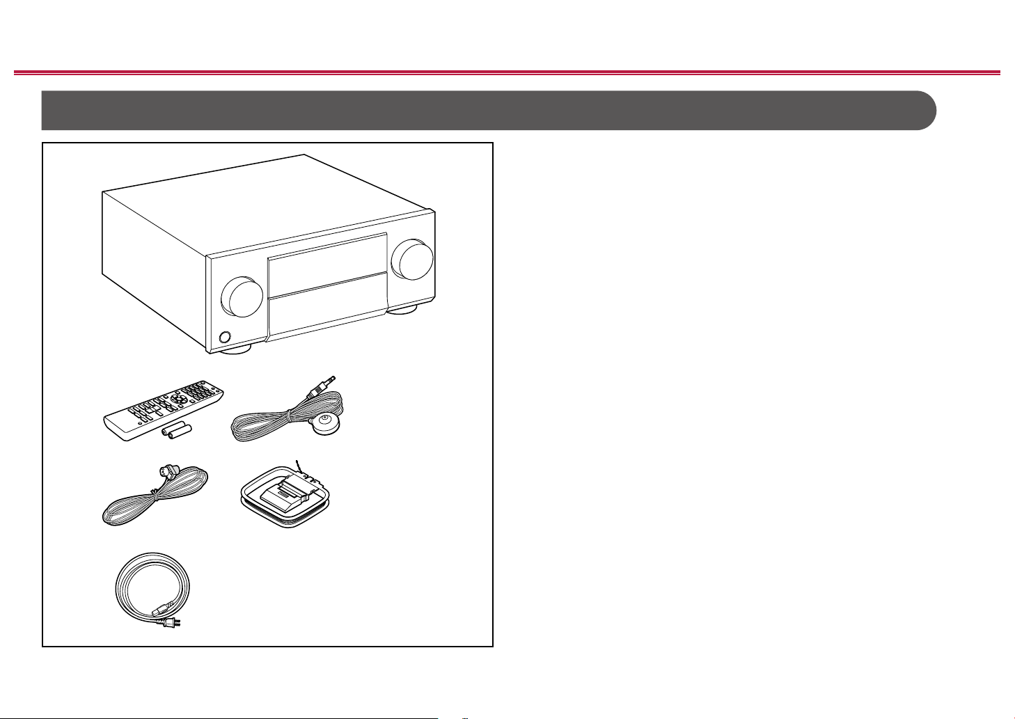
What’s in the box
Contents ≫ Connections ≫ Playback ≫ Setup
1. Main unit (1)
2. Remote controller (RC-977R) (1), Batteries (AAA/R03) (2)
3. Speaker setup microphone (1)
• Used during Initial Setup.
4. Indoor FM antenna (1)
5. AM loop antenna (1)
6. Power cord (1)
• Initial Setup Guide (1)
* This document is an online instruction manual. It is not included as an
accessory.
• Connect speakers with an impedance of 4 Ω to 16 Ω.
• The power cord must be connected only after all other connections are
completed.
• We will not accept any responsibility for damage arising from the connection
with equipment manufactured by other companies.
• Network services and content that can be used may no longer be available
if new functions are added by updating rmware or the service providers
terminate their services. Also, available services may differ depending on your
area.
• Details on the rmware update will be posted on our website and through
other means at a later date.
• Specications and appearance are subject to change without prior notice.
≫
5
Front Panel≫ Rear Panel≫ Remote≫
Page 6
Contents ≫ Connections ≫ Playback ≫ Setup
Additional Function (Firmware Update)
This unit is equipped with a function to update the rmware via network or USB port when the rmware update is announced after purchase. This enables various
functions to be added and operations to be improved.
Depending on the manufacturing timing of the product, the rmware may be switched to the updated one. In such a case, new functions may be added from the start.
For how to conrm the latest rmware contents and the rmware version of your product, see the following section.
Update Information of the rmware
For the latest rmware contents and the rmware version, visit our company’s website. If the rmware version of your product differs from the latest one, it is
recommended to update the rmware.
To conrm the rmware version of your product, press the button on the remote controller to display the Home screen, and refer to "System Setup" - "Miscellaneous"
- "Firmware Update" - "Version" ( p178).
Operation of added new functions
If functions are added or changed from contents described in the Instruction Manual, see the following reference.
Supplementary Information ≫
≫
Firmware Update Procedure ( p7)
6
Front Panel≫ Rear Panel≫ Remote≫
Page 7

Firmware Update Procedure
Contents ≫ Connections ≫ Playback ≫ Setup
≫
The update may take approx. 30 minutes to complete via network or via USB
port. Existing settings are guaranteed in either updating method.
When this unit is connected to the network, notications of rmware updates may
be displayed. To update the rmware, select "Update Now" with the cursors on
the remote controller, and press the ENTER button. The unit automatically enters
standby mode after "Completed!" is displayed, and the update is completed.
Disclaimer: The program and accompanying online documentation are furnished
to you for use at your own risk.
Our company will not be liable and you will have no remedy for damages for
any claim of any kind whatsoever concerning your use of the program or the
accompanying online documentation, regardless of legal theory, and whether
arising in tort or contract.
In no event will our company be liable to you or any third party for any special,
indirect, incidental, or consequential damages of any kind, including, but not
limited to, compensation, reimbursement or damages on account of the loss of
present or prospective prots, loss of data, or for any other reason whatsoever.
Updating the Firmware via Network
• While updating the rmware, do not do the following:
– Disconnecting and reconnecting cables, USB storage device, speaker
setup microphone or headphones, or performing operations on the unit
such as turning the power off
– Accessing this unit from a PC or smartphone using their applications
• Check that the unit is turned on, and the connection to the Internet is secured.
• Turn off the controller components (PC etc.) connected to the network.
• Stop any playing Internet radio, USB storage device, or server content.
• If the multi-zone function is active, turn it off.
• If "HDMI CEC" is set to "On", set it to "Off".
– Press to display the Home screen. Next, select "System Setup" -
"Hardware" - "HDMI", press ENTER, select "HDMI CEC" and select "Off".
* The descriptions may differ from the actual on-screen displays, however, operations
and functions are the same.
Update
1. Press .
The Home screen is displayed on the TV screen.
2. Select "System Setup" - "Miscellaneous" - "Firmware Update" - "Update via
NET" with the cursors in order, then press ENTER.
• If "Firmware Update" is grayed out and cannot be selected, wait for a while
until it starts up.
• If there is no updatable rmware, "Update via NET" cannot be selected.
3. Press ENTER with "Update" selected, and start update.
• During the update, the TV screen may go black depending on the program
to be updated. In such a case, check the progress on the display of the
unit. The TV screen will remain black until the update is completed and the
power is turned on again.
• When "Completed!" is displayed, the update is complete.
4. Press
The process is completed, and your rmware is updated to the latest version.
STANDBY/ON on the main unit to turn the unit into standby mode.
• Do not use
on the remote controller.
7
Front Panel≫ Rear Panel≫ Remote≫
Page 8

Contents ≫ Connections ≫ Playback ≫ Setup
≫
If an Error Message is Displayed
If an error occurs, "- Error!" is displayed on the display of the unit. (""
represents an alphanumeric character.) Refer to the following descriptions and
check.
Error Code
• -01, -10:
LAN cable not found. Connect the LAN cable properly.
• -02, -03, -04, -05, -06, -11, -13, -14, -16, -17, -18, -20,
-21:
Internet connection error. Check the following:
– Whether the router is turned on
– Whether this unit and the router are connected via the network
Unplug and plug the power cords of this unit and the router. This may solve
the problem. If you are still unable to connect to the Internet, the DNS server
or proxy server may be temporarily down. Check the server operation status
with your Internet service provider.
• Others:
After removing the power plug once, insert it to the outlet, and then start the
operation from the beginning.
Updating via USB
• While updating the rmware, do not do the following:
– Disconnecting and reconnecting cables, USB storage device, speaker
setup microphone or headphones, or performing operations on the unit
such as turning the power off
– Accessing this unit from a PC or smartphone using their applications
• Prepare a 256 MB or larger USB storage device. The format of USB storage
devices supports FAT16 or FAT32 le system format.
– Media inserted into a USB card reader may not be used for this function.
–
USB storage devices equipped with the security function are not supported.
– USB hubs and USB devices equipped with the hub function are not
supported. Do not connect these devices to the unit.
• Delete any data stored on the USB storage device.
• Turn off the controller components (PC etc.) connected to the network.
• Stop any playing Internet radio, USB storage device, or server content.
• If the multi-zone function is active, turn it off.
• If "HDMI CEC" is set to "On", set it to "Off".
– Press
"Hardware" - "HDMI", press ENTER, select "HDMI CEC" and select "Off".
* Depending on the USB storage device or its content, long time may be required
for loading, the content may not be loaded correctly, or power may not be supplied
correctly.
* Our company will not be liable whatsoever for any loss or damage of data, or storage
failure arising from the use of the USB storage device. Please note this in advance.
* The descriptions may differ from the actual on-screen displays, however, operations
and functions are the same.
Update
1. Connect the USB storage device to your PC.
2. Download the rmware le from our company's website to your PC and unzip.
Firmware les are named as below.
PIOAVR_R.zip
Unzip the le on your PC. The number of unzipped les and folders varies
depending on the model.
3. Copy all unzipped les and folders to the root folder of the USB storage
device.
• Make sure to copy the unzipped les.
4. Connect the USB storage device to the USB port of this unit.
• If an AC adapter is supplied with the USB storage device, connect the AC
adapter, and use it with a household outlet.
• If the USB storage device has been partitioned, each section will be treated
as an independent device.
5. Press .
The Home screen is displayed on the TV screen.
6. Select "System Setup" - "Miscellaneous" - "Firmware Update" - "Update via
USB" with the cursors in order, then press ENTER.
to display the Home screen. Next, select "System Setup" -
8
Front Panel≫ Rear Panel≫ Remote≫
Page 9

Contents ≫ Connections ≫ Playback ≫ Setup
• If "Firmware Update" is grayed out and cannot be selected, wait for a while
until it starts up.
• If there is no updatable rmware, "Update via USB" cannot be selected.
7. Press ENTER with "Update" selected, and start update.
• During the update, the TV screen may go black depending on the program
to be updated. In such a case, check the progress on the display of the
unit. The TV screen will remain black until the update is completed and the
power is turned on again.
• During the update, do not turn the power off, or disconnect or reconnect the
USB storage device.
• When "Completed!" is displayed, the update is complete.
8. Disconnect the USB storage device from the unit.
9. Press STANDBY/ON on the main unit to turn the unit into standby mode.
The process is completed, and your rmware is updated to the latest version.
• Do not use on the remote controller.
If an Error Message is Displayed
If an error occurs, "- Error!" is displayed on the display of the unit. (""
represents an alphanumeric character.) Refer to the following descriptions and
check.
Error Code
• -01, -10:
The USB storage device cannot be recognized. Check if the USB storage
device or USB cable is securely inserted to the USB port of the unit.
Connect the USB storage device to an external power source if it has its own
power supply.
• -05, -13, -20, -21:
The rmware le is not present in the root folder of the USB storage device, or
the rmware le is for another model. Retry from the download of the rmware
le.
≫
• Others:
After removing the power plug once, insert it to the outlet, and then start the
operation from the beginning.
9
Front Panel≫ Rear Panel≫ Remote≫
Page 10
Contents ≫ Connections ≫ Playback ≫ Setup
Part Names
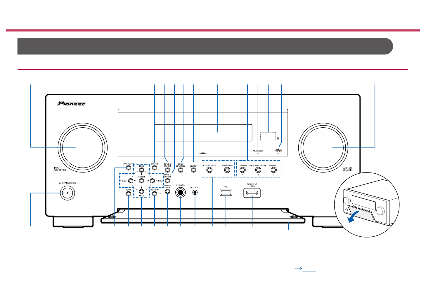
Front Panel
≫
10
For details, see ( p11)
Front Panel≫ Rear Panel≫ Remote≫
Page 11

Contents ≫ Connections ≫ Playback ≫ Setup
≫
1. INPUT SELECTOR dial: Switch the input to be played.
2. STATUS button: Switches the information on the display. ( p136)
3. ZONE 2 ON/OFF button: Turns ZONE 2 ON/OFF. ( p124)
4. ZONE 3 ON/OFF button: Turns ZONE 3 ON/OFF. ( p126)
5. ZONE CONTROL button: Controls the multi-zone function. ( p123)
6. DIMMER button: You can switch the display off or adjust the brightness of the
display in three steps.
7. Display ( p12)
8. PERSONAL PRESET 1/2/3 buttons: Registers the current setting conditions
such as input selector, listening mode, etc. or call the registered settings.
( p128)
9. NETWORK indicator: This lights when "NET" is selected with the input
selector and the unit is connected to the network. Lights up when any of the
following functions is working or enabled in standby state of this unit. When
this indicator is lighting, the power consumption in standby state increases,
however, the increase in power consumption is minimized by entering the
HYBRID STANDBY mode where only the essential circuits operate. It does not
light when ZONE 2/ZONE 3 is on, however.
– HDMI CEC ( p167)
– HDMI Standby Through ( p168)
– USB Power Out at Standby ( p169)
– Network Standby ( p169)
– Bluetooth Wakeup ( p170)
10.
Remote control sensor: Receives signals from the remote controller.
• The signal range of the remote controller is within about 16´/5 m, at an
angle of 20° on the perpendicular axis and 30° to either side.
11.
MCACC PRO indicator: This lights when you have enabled the speaker
calibration made with MCACC. ( p180, 201)
12.
MASTER VOLUME
13.
STANDBY/ON button: When the power is turned on, the periphery of the
button lights up. This lights dimly when you have pressed number 7 DIMMER
repeatedly to turn the display off.
14.
AV ADJUST button: Settings such as "HDMI" and "Audio" can be made quickly
during play on the TV screen. ( p196)
15.
HOME button: Displays the Home. ( p152, 179, 192)
16.
Cursor buttons ( / / / ) and ENTER button: Select the item with the
cursors and press ENTER to conrm. Use them to tune to stations when using
TUNER. ( p118)
17.
RETURN button: Returns the display to the previous state.
18.
TUNING MODE button: Switches the tuning mode. ( p118)
19.
PHONES jack: Headphones with a standard plug (ø1/4"/6.3 mm) are
connected.
20.
SETUP MIC jack: The supplied speaker setup microphone is connected.
( p180, 201)
21.
Listening mode button: Switches the listening mode. ( p134)
22.
USB port: A USB storage device is connected so that music les stored in it
can be played. ( p104)
23.
AUX INPUT HDMI jack: Connect a video camera, etc. using an HDMI cable.
( p84)
24.
Front ap
11
Front Panel≫ Rear Panel≫ Remote≫
Page 12
Display
Contents ≫ Connections ≫ Playback ≫ Setup
≫
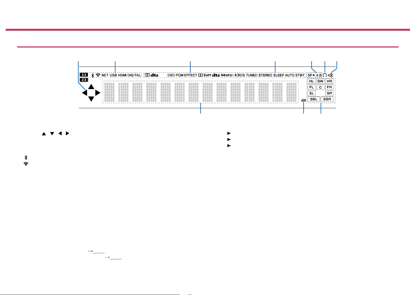
1. Cursor ( / / / ): This may light when performing operations with the
"NET", "USB" input selector.
2. Lights in the following conditions.
Z2/Z3: ZONE 2/ZONE 3 is on.
: Connected by BLUETOOTH.
: Connected by Wi-Fi.
NET: Lights when connected to the network with the "NET" input selector. It
will blink if incorrectly connected to the network.
USB: Lights when the "USB" input selector is selected, a USB device is
connected and the USB input is selected. It will blink if the USB device is not
properly connected.
HDMI: HDMI signals are input and the HDMI input is selected.
DIGITAL: Digital signals are input and the digital input is selected.
3. Lights according to the type of input digital audio signal and the listening
mode.
4. Lights in the following conditions.
5. Displays the audio output destination.
RDS (European models): Receiving RDS broadcasting.
TUNED: Receiving AM/FM radio.
STEREO: Receiving FM stereo.
SLEEP: Sleep timer is set. ( p169)
AUTO STBY: Auto Standby is set. ( p169)
SP A: Outputs audio only to SPEAKER A.
SP B: Outputs audio only to SPEAKER B.
SP AB: Outputs audio to both SPEAKER A and SPEAKER B.
A: Outputs audio only to ZONE A.
B: Outputs audio only to ZONE B.
AB: Outputs audio to both ZONE A and ZONE B.
6. Lights when headphones are connected.
7. Blinks when muting is on.
8. Displays various information of the input signals.
9. Lights when adjusting the volume.
10.
Speaker/Channel display: Displays the output channel that corresponds to the
selected listening mode.
12
Front Panel≫ Rear Panel≫ Remote≫
Page 13
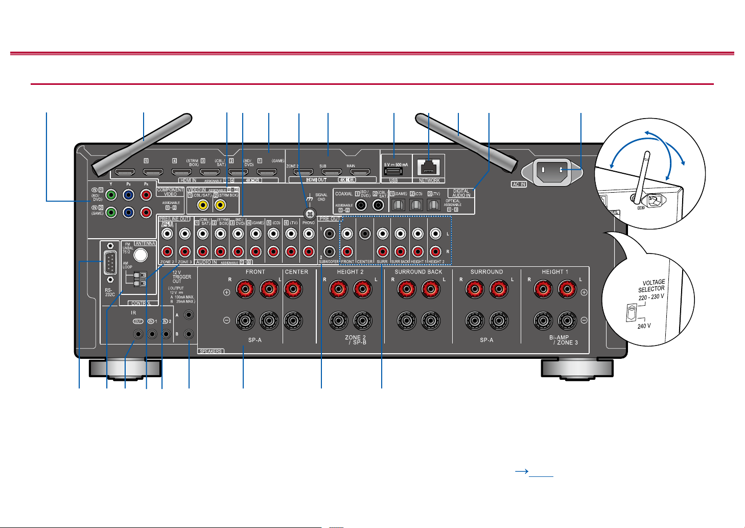
Rear Panel
180°
90°
4K HDR
Contents ≫ Connections ≫ Playback ≫ Setup
ARC
5 V 500 mA
eARC
HDMI OUT
4K HDR
USB
≫
ZONE B
(LINE OUT)
For details, see ( p14)
13
Front Panel≫ Rear Panel≫ Remote≫
Page 14

Contents ≫ Connections ≫ Playback ≫ Setup
≫
1. COMPONENT VIDEO IN jacks: Input the AV component video signals with a
component video cable. (Compatible only with 480i or 576i resolution.)
2. Wireless antenna: Used for Wi-Fi connection or when using a BLUETOOTH
enabled device. Adjust their angles according to the connection status.
3. VIDEO IN jacks: Input the AV component video signals with an analog video
cable.
4.
AUDIO IN jacks: Input AV component audio signal with an analog audio cable.
5. HDMI IN jacks: Transmit video signals and audio signals with a HDMI cable
connected to an AV component.
6. SIGNAL GND terminal: The ground wire of the turntable is connected.
7. HDMI OUT jacks: Transmit video signals and audio signals with an HDMI
cable connected to a monitor such as a TV or projector.
8. USB port: A USB storage device is connected so that music les stored in it
can be played. ( p104)
You can also supply power (5 V/0.5 A) to USB devices with a USB cable.
9. NETWORK port: Connect to the network with a LAN cable.
10.
DIGITAL AUDIO IN OPTICAL/COAXIAL jacks: Input TV or AV component
digital audio signals with a digital optical cable or digital coaxial cable.
11.
AC IN: The supplied power cord is connected.
12.
RS-232C port: Connect a home control system equipped with an RS-232C
port. For adopting a home control system, contact the specialized stores.
13.
ANTENNA AM LOOP/FM UNBAL 75 Ω terminal: The supplied antennas are
connected.
14.
IR IN/OUT port: Connect a remote control receiver unit. ( p91)
15.
ZONE 2 PRE/LINE OUT jacks: Output audio signals with an analog audio
cable connected to a pre-main amplier or a power amplier in a separate
room (ZONE 2).
ZONE B LINE OUT jacks: Connect to a pre-main amplier with an analog
audio cable, and simultaneously output audio of the same source as that of
the speakers (ZONE A) connected to this unit.
16.
ZONE 3 PRE/LINE OUT jacks: Output audio signals with an analog audio
cable connected to a pre-main amplier or a power amplier in a separate
room (ZONE 3).
17.
12V TRIGGER OUT A/B jack: Connect a device equipped with a 12V trigger
input jack to enable power link operation between the device and this unit.
( p92)
18.
SPEAKERS terminals: Connect speakers with speaker cables. (North
American models support banana plugs. Use a plug 4 mm in diameter. Y plug
connection is not supported.)
19.
SUBWOOFER PRE OUT jack: Connect a powered subwoofer with a
subwoofer cable. Up to two powered subwoofers can be connected. You can
set the volume levels of the 2 powered subwoofers to different levels.
( p163)
20.
PRE OUT jacks: Connect a power amplier. ( p75)
21.
VOLTAGE SELECTOR (multi-voltage models): Use a medium-sized
screwdriver to switch the voltage to the one appropriate for your region. Before
changing the voltage, rst disconnect the power cord.
14
Front Panel≫ Rear Panel≫ Remote≫
Page 15
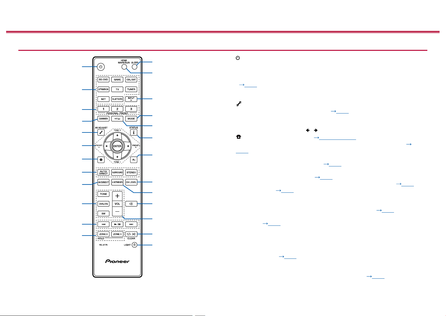
Remote Controller
Contents ≫ Connections ≫ Playback ≫ Setup
≫
1. STANDBY/ON button
2. INPUT button: Switch the input to be played.
3. PERSONAL PRESET 1/2/3 buttons: Registers the current setting conditions
such as input selector, listening mode, etc. or call the registered settings.
( p128)
4.
DIMMER button: You can switch the display off or adjust the brightness of the
display in three steps.
5. (AV ADJUST) button: Settings such as "HDMI" and "Audio" can be made
quickly during play on the TV screen. ( p196)
6. Cursor buttons and ENTER button: Select the item with the cursors and press
ENTER to conrm your selection. When the folder or le lists are not shown on
one screen on the TV, press / to change the screen.
7. button: Displays the Home. ( p152, 179, 192)
8. LISTENING MODE buttons: Allows you to select the listening mode. (
p134)
9. AV DIRECT button: Sound quality can be improved by suppressing the noise
that is generated in digital circuits. ( p132)
10.
TONE/DIALOG/SW buttons: Adjusts the sound quality of the speakers and
volume level of the subwoofer. ( p130)
11.
Play buttons: Used for playback operations for the Music Server ( p107)
or USB device ( p104). If the unit is switched to "CEC MODE" using
"16. MODE button", an HDMI CEC function-enabled AV component can be
operated. (Depending on the device, operation may not be possible.)
12.
ZONE 2/ZONE 3 button: Controls the multi-zone function. ( p123)
13.
SLEEP button: Set the sleep timer. Select the time from "30 min", "60 min" and
"90 min". ( p133)
14.
HDMI MAIN/SUB button: Select the HDMI OUT jack to output video signals
from "MAIN", "SUB", and "MAIN+SUB".
15.
INPUT > button: Switches the input to be played.
16.
MODE button: Switches between automatic tuning and manual tuning for
AM/FM stations ( p118). Also, when an HDMI CEC function-enabled
AV component is connected to this unit, you can switch "11. Play buttons"
between "CEC MODE" and "RCV MODE" (normal mode).
17.
+Fav button: Used to register AM/FM radio stations. ( p120)
15
Front Panel≫ Rear Panel≫ Remote≫
Page 16

Contents ≫ Connections ≫ Playback ≫ Setup
18.
(STATUS) button: Switches the information on the display and is used to
operate RDS. ( p122)
19.
button: Returns the display to the previous state.
20.
CH LEVEL button: You can check the volume level settings ( p162) for
each of the speakers. You can also change the settings with the number 6
cursor buttons / .
21.
S.RETRIEVER button: Enable Sound Retriever ( p197) and improve the
quality of compressed audio.
22.
button: Temporarily mutes audio. Press again to cancel muting.
23.
Volume buttons
24.
25. (LIGHT) button: Turn the backlight of the remote controller On/Off. If
button: You can start repeat or random play of the Music Server or
USB.
CLEAR button: Deletes all characters you have entered when entering text on
the TV screen.
10 seconds elapse with no operations performed after turning it on, it will
automatically turn off.
≫
16
Front Panel≫ Rear Panel≫ Remote≫
Page 17
Contents ≫ Connections ≫ Playback ≫ Setup
Connections
Connecting speakers 18
Connecting the TV 78
Connecting Playback Devices 81
Connecting an AV Component in a Separate Room
(Multi-zone Connection) 85
Connecting ZONE B 88
Connecting Antennas 89
Network Connection 90
Connecting External Control Devices 91
Connecting the Power Cord 93
≫
17
Front Panel≫ Rear Panel≫ Remote≫
Page 18
Contents ≫ Connections ≫ Playback ≫ Setup
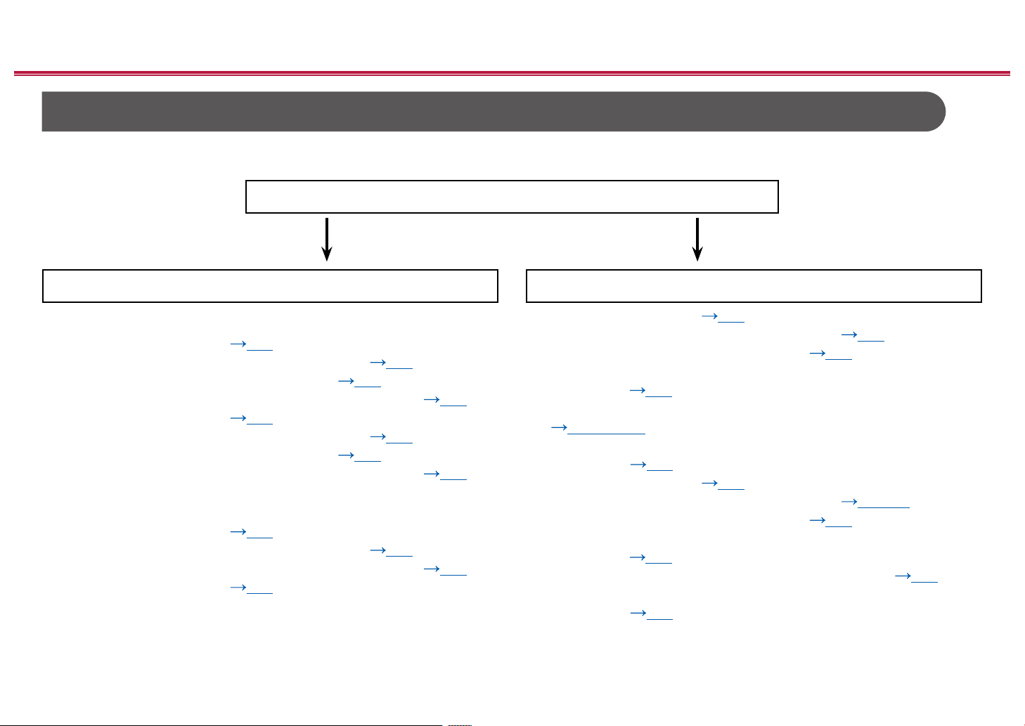
Connecting speakers
You can select the layout of speakers to be installed from various patterns when using this unit. Use the following ow chart to select the speaker layout that suits your
speakers and usage environment. You can check the connection method and default settings.
Use height speakers?
Yes No
≫
When using 1 set of Height Speakers
• 5.1.2 Channel System ( p63)
• 5.1.2 Channel System + ZONE SPEAKER (
• 5.1.2 Channel System + SPEAKER B ( p65)
• 5.1.2 Channel System (Bi-Amping the Speakers) ( p66)
• 7.1.2 Channel System ( p67)
• 7.1.2 Channel System + ZONE SPEAKER (
• 7.1.2 Channel System + SPEAKER B (
• 7.1.2 Channel System (Bi-Amping the Speakers) ( p70)
p64)
p68)
p69)
When using 2 sets of Height Speakers
• 5.1.4 Channel System ( p71)
• 5.1.4 Channel System + ZONE SPEAKER ( p72)
• 5.1.4 Channel System (Bi-Amping the Speakers) ( p73)
• 7.1.4 Channel System ( p74)
• 5.1 Channel System ( p48)
• 5.1 Channel System + ZONE SPEAKER ( p49)
• 5.1 Channel System + SPEAKER B ( p50)
• 5.1 Channel System + SPEAKER B (Bi-Amping the
Speakers) ( p51)
• 5.1 Channel System (Bi-Amping the Speakers)
( p52, 53, 54)
• 5.1 Channel System (Bi-Amping the Speakers) + ZONE
SPEAKER ( p55)
• 7.1 Channel System ( p56)
• 7.1 Channel System + ZONE SPEAKER ( p57, 58)
• 7.1 Channel System + SPEAKER B ( p59)
• 7.1 Channel System + SPEAKER B (Bi-Amping the
Speakers) ( p60)
• 7.1 Channel System (Bi-Amping the Speakers) ( p61)
• 7.1 Channel System (Bi-Amping the Speakers) + ZONE
SPEAKER ( p62)
18
Front Panel≫ Rear Panel≫ Remote≫
Page 19
Speaker Installation
Contents ≫ Connections ≫ Playback ≫ Setup
≫
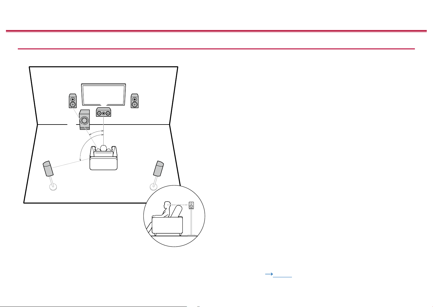
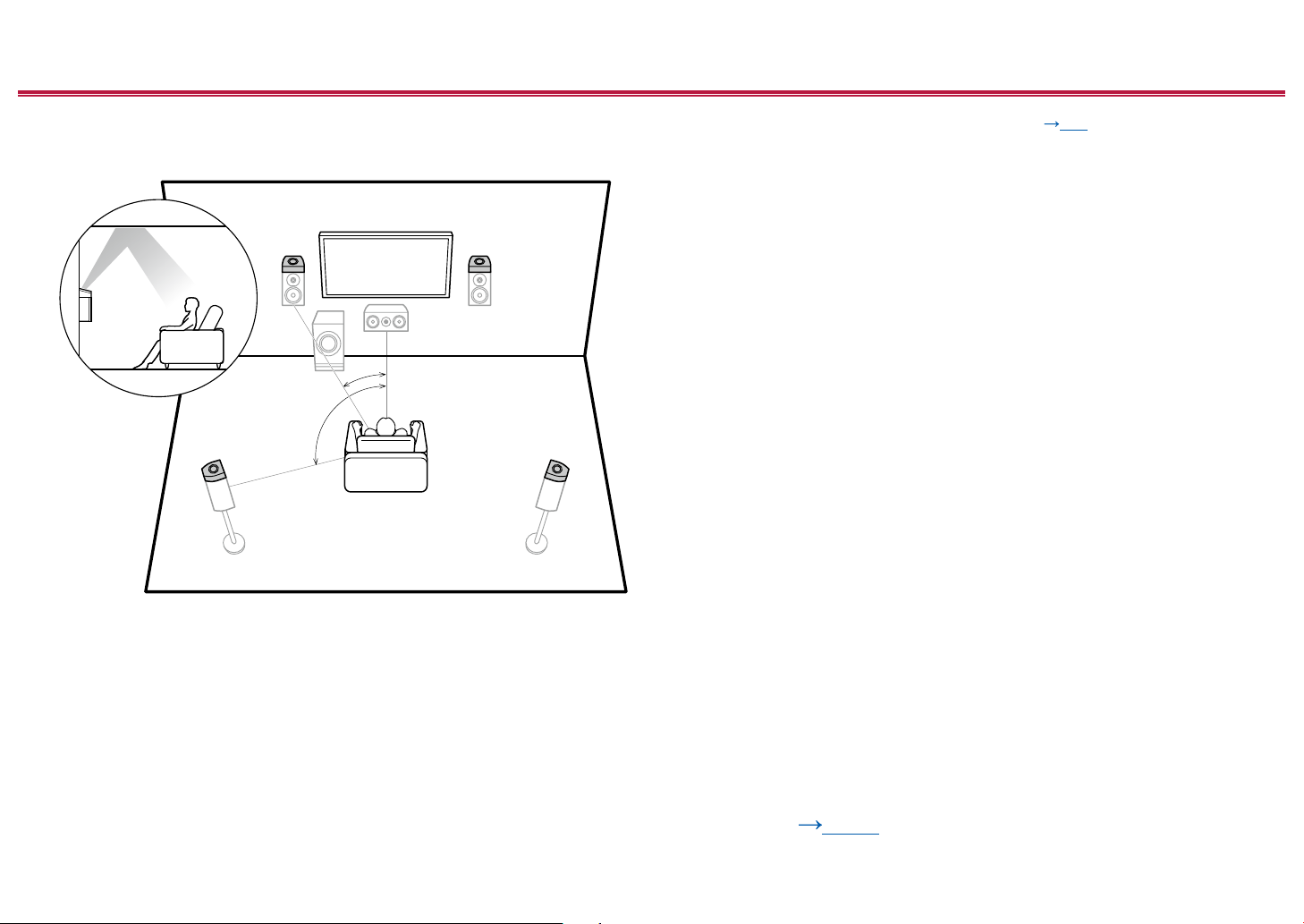
5.1 Channel System
a: 22° to 30°, b: 120°
a
b
This is a basic 5.1 Channel System. Front speakers output the front stereo
sound, and a center speaker outputs the sound of the center of the screen, such
as dialogs and vocals. Surround speakers create the back sound eld. Powered
subwoofer reproduces the bass sound, and creates the rich sound eld.
The front speakers should be positioned at ear height while the surround
speakers should be positioned just above ear height. The center speaker
should be set up facing the listening position at an angle. Placing the powered
subwoofer between the center speaker and the front speaker gives you a natural
sound even when playing music sources.
1,2 Front Speakers
3 Center Speaker
4,5 Surround Speakers
6 Powered Subwoofer
Speaker Layouts and Selectable Listening
Modes ( p137)
19
Front Panel≫ Rear Panel≫ Remote≫
Page 20
Contents ≫ Connections ≫ Playback ≫ Setup
≫
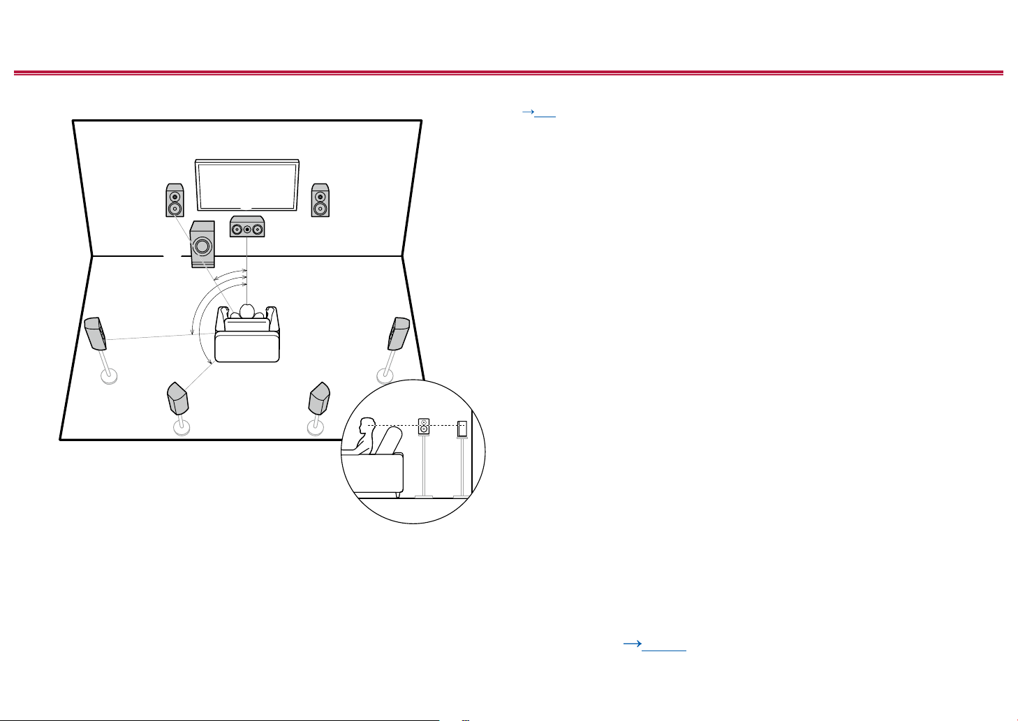
7.1 Channel System
a
b
c
a: 22° to 30°, b: 90° to 110°, c: 135° to 150°
This is a 7.1 Channel System that consists of the basic 5.1 Channel System (
p19) and added surround back speakers. Front speakers output the front
stereo sound, and a center speaker outputs the sound of the center of the
screen, such as dialogs and vocals. Surround speakers create the back sound
eld. Powered subwoofer reproduces the bass sound, and creates the rich
sound eld. Surround back speakers improves the sense of envelopment and
connectivity of sound in the back sound eld, and provides a more real sound
eld.
The front speakers should be positioned at ear height while the surround
speakers should be positioned just above ear height. The center speaker
should be set up facing the listening position at an angle. Placing the powered
subwoofer between the center speaker and the front speaker gives you a natural
sound even when playing music sources. The surround back speakers should be
positioned at ear height.
• If surround back speakers are installed, be sure to install surround speakers
as well.
1,2 Front Speakers
3 Center Speaker
4,5 Surround Speakers
6 Powered Subwoofer
7,8 Surround Back Speakers
Speaker Layouts and Selectable Listening
Modes ( p137)
20
Front Panel≫ Rear Panel≫ Remote≫
Page 21

Contents ≫ Connections ≫ Playback ≫ Setup
5.1.2 Channel System
A 5.1.2 Channel System is a speaker layout consisting of the basic 5.1 Channel System ( p19) and added height speakers. Select the height speakers that suit
your speakers and usage environment from the following three types.
Front High Speakers/Rear High Speakers
Installation Example (
Ceiling Speakers Installation Example
(
p23)
Dolby Enabled Speakers (Dolby Speakers)
Installation Example (
p22)
p24)
≫
21
Front Panel≫ Rear Panel≫ Remote≫
Page 22
Contents ≫ Connections ≫ Playback ≫ Setup
≫
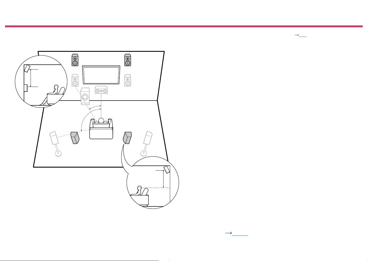
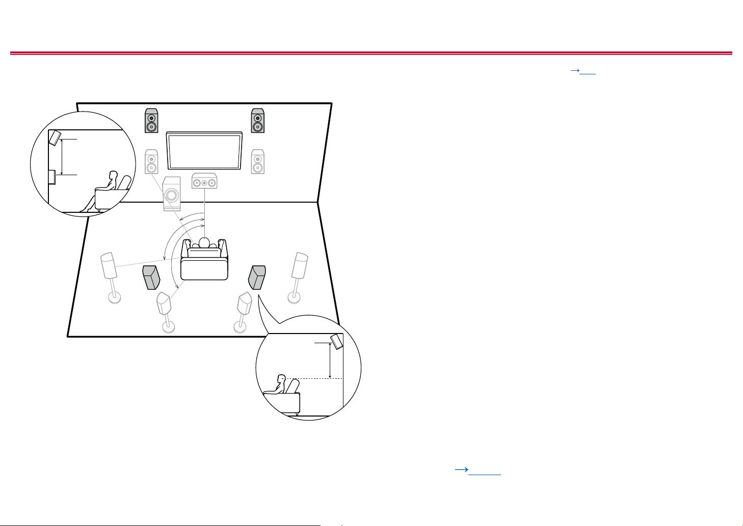
Front High Speakers/Rear High Speakers
Installation Example
3´ (0.9 m)
or more
a
a: 22° to 30°, b: 120°
b
3´ (0.9 m)
or more
This is a system with the basic 5.1 channel system ( p19) consisting of
front speakers, a center speaker, surround speakers and a powered subwoofer,
and added front high speakers or rear high speakers combined. Installing the
height speakers will enrich the sound eld feeling in the upper space. Front high
speakers or rear high speakers should be installed at least 3´/0.9 m higher than
the front speakers.
Front high speakers should be installed directly above the front speakers, and the
distance between the rear high speakers should match the distance between the
front speakers. In both cases, the speakers should be set up facing the listening
position at an angle.
7,8 Height Speakers
Choose one of the following:
• Front High Speakers
• Rear High Speakers
22
Speaker Layouts and Selectable Listening
Modes ( p137)
Front Panel≫ Rear Panel≫ Remote≫
Page 23
Contents ≫ Connections ≫ Playback ≫ Setup
≫
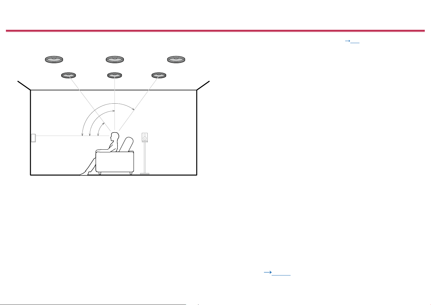
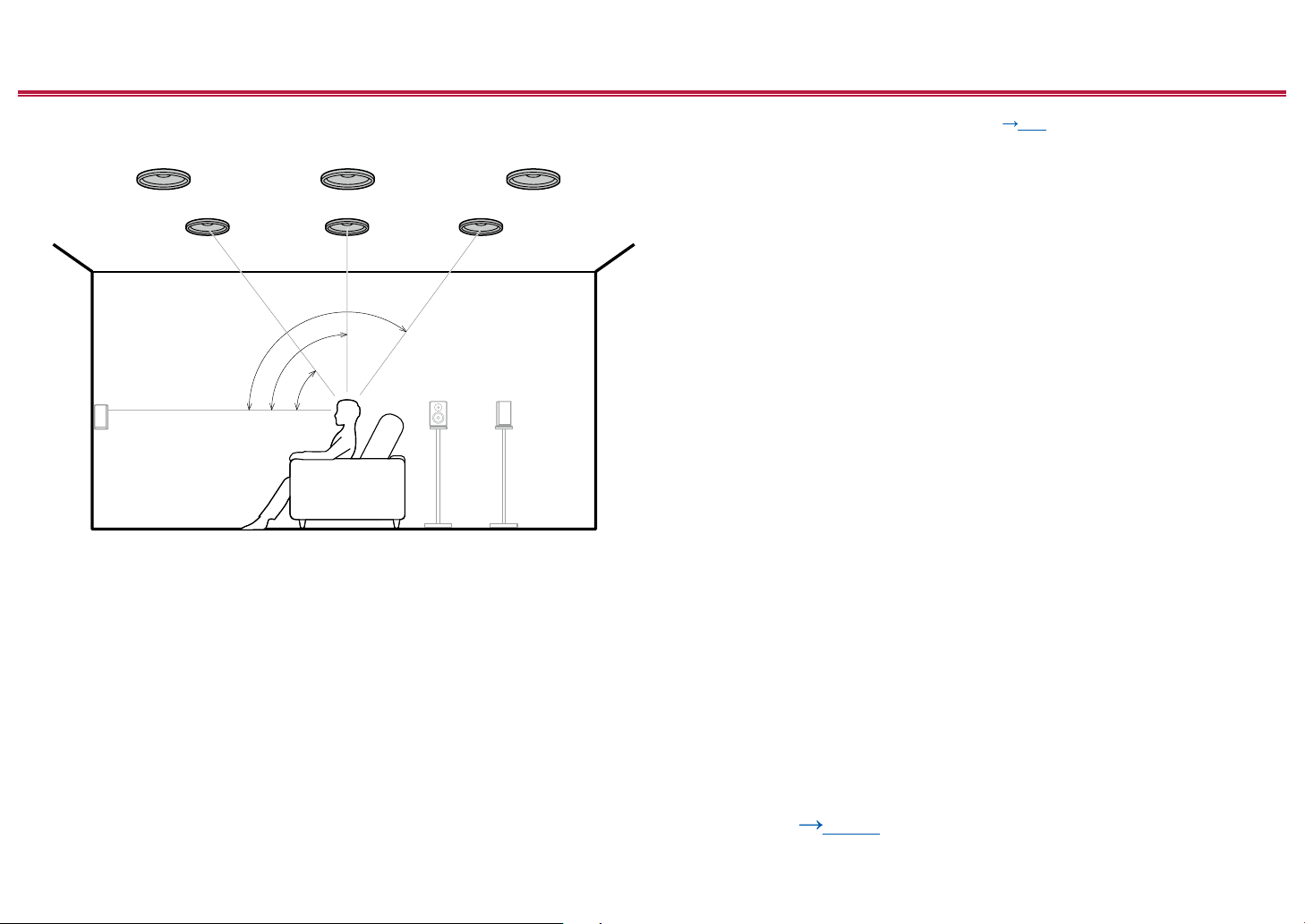
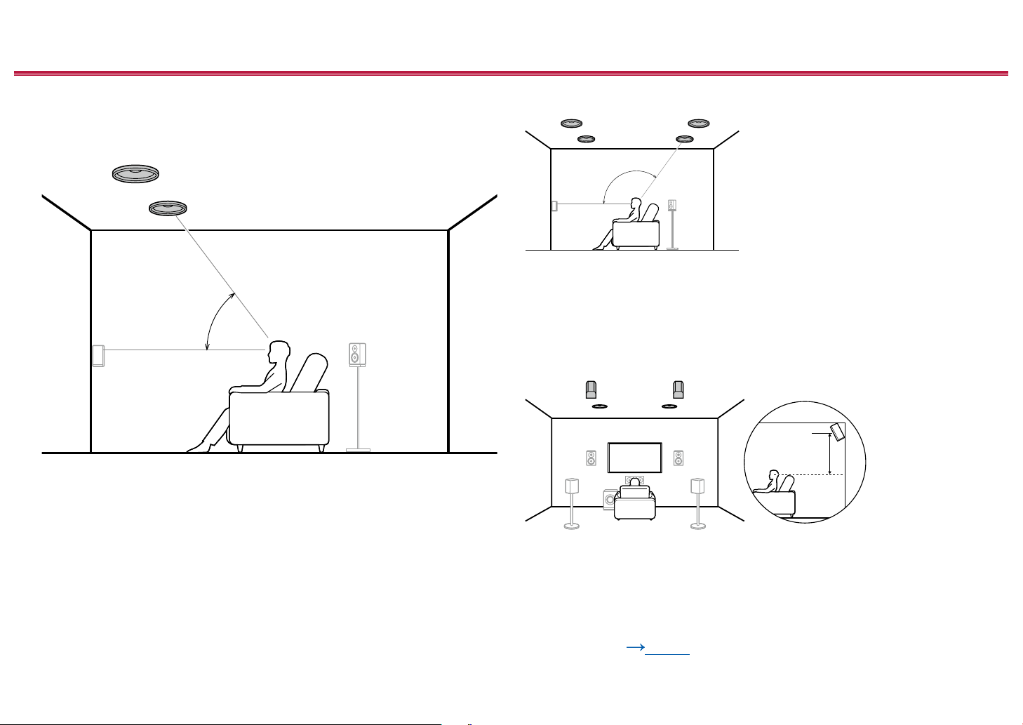
Ceiling Speakers Installation Example
a: 30° to 55°, b: 65° to 100°, c: 125° to 150°
b
a
c
This is a system with the basic 5.1 channel system ( p19) consisting of front
speakers, a center speaker, surround speakers and a powered subwoofer, and
added top front speakers or top middle speakers or top rear speakers combined.
Installing the height speakers will enrich the sound eld feeling in the upper
space. Install the top front speakers on the ceiling anterior to the seating position,
top middle speakers on the ceiling directly above the seating position, and top
rear speakers on the ceiling posterior to the seating position. The distance
between each pair should match the distance between the front speakers.
• Dolby Laboratories recommends the setups of these types of height speakers
to obtain the best Dolby Atmos effect.
7,8 Height Speakers
Choose one of the following:
• Top Front Speakers
• Top Middle Speakers
• Top Rear Speakers
Speaker Layouts and Selectable Listening
Modes ( p137)
23
Front Panel≫ Rear Panel≫ Remote≫
Page 24
Contents ≫ Connections ≫ Playback ≫ Setup
≫
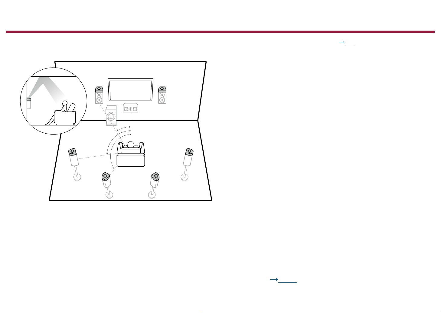
Dolby Enabled Speakers (Dolby Speakers)
Installation Example
a
b
a: 22° to 30°, b: 120°
This is a system with the basic 5.1 channel system ( p19) consisting of front
speakers, a center speaker, surround speakers and a powered subwoofer, and
added Dolby enabled speakers (front) or Dolby enabled speakers (surround)
combined. Dolby enabled speakers are special speakers designed to face the
ceiling, so that the sound is heard from overhead by bouncing the sound off the
ceiling. Installing the height speakers will enrich the sound eld feeling in the
upper space.
Install them either on the front speakers or on the surround speakers.
7,8 Height Speakers
Choose one of the following:
• Dolby Enabled Speakers (Front)
• Dolby Enabled Speakers (Surround)
Speaker Layouts and Selectable Listening
Modes ( p137)
24
Front Panel≫ Rear Panel≫ Remote≫
Page 25

Contents ≫ Connections ≫ Playback ≫ Setup
7.1.2 Channel System
A 7.1.2 Channel System is a speaker layout consisting of the 7.1 Channel System ( p20) and added height speakers. Select the height speakers that suit your
speakers and usage environment from the following three types.
Front High Speakers/Rear High Speakers
Installation Example (
Ceiling Speakers Installation Example
(
p27)
Dolby Enabled Speakers (Dolby Speakers)
Installation Example (
p26)
p28)
≫
25
Front Panel≫ Rear Panel≫ Remote≫
Page 26
Contents ≫ Connections ≫ Playback ≫ Setup
≫
Front High Speakers/Rear High Speakers
Installation Example
3´ (0.9 m)
or more
a
a: 22° to 30°, b: 90° to 110°, c: 135° to 150°
b
c
3´ (0.9 m)
or more
This is a system with the 7.1 channel system ( p20) consisting of front
speakers, a center speaker, surround speakers, surround back speakers and
a powered subwoofer, and added front high speakers or rear high speakers
combined. Installing the height speakers will enrich the sound eld feeling in the
upper space. Front high speakers or rear high speakers should be installed at
least 3´/0.9 m higher than the front speakers.
Front high speakers should be installed directly above the front speakers, and the
distance between the rear high speakers should match the distance between the
front speakers. In both cases, the speakers should be set up facing the listening
position at an angle.
9,10 Height Speakers
Choose one of the following:
• Front High Speakers
• Rear High Speakers
26
Speaker Layouts and Selectable Listening
Modes ( p137)
Front Panel≫ Rear Panel≫ Remote≫
Page 27
Contents ≫ Connections ≫ Playback ≫ Setup
≫
Ceiling Speakers Installation Example
a: 30° to 55°, b: 65° to 100°, c: 125° to 150°
b
a
c
This is a system with the 7.1 channel system ( p20) consisting of front
speakers, a center speaker, surround speakers, surround back speakers and a
powered subwoofer, and added top front speakers or top middle speakers or top
rear speakers combined. Installing the height speakers will enrich the sound eld
feeling in the upper space. Install the top front speakers on the ceiling anterior to
the seating position, top middle speakers on the ceiling directly above the seating
position, and top rear speakers on the ceiling posterior to the seating position.
The distance between each pair should match the distance between the front
speakers.
• Dolby Laboratories recommends the setups of these types of height speakers
to obtain the best Dolby Atmos effect.
9,10 Height Speakers
Choose one of the following:
• Top Front Speakers
• Top Middle Speakers
• Top Rear Speakers
Speaker Layouts and Selectable Listening
Modes ( p137)
27
Front Panel≫ Rear Panel≫ Remote≫
Page 28
Contents ≫ Connections ≫ Playback ≫ Setup
≫
Dolby Enabled Speakers (Dolby Speakers)
Installation Example
a
b
c
a: 22° to 30°, b: 90° to 110°, c: 135° to 150°
This is a system with the 7.1 channel system ( p20) consisting of front
speakers, a center speaker, surround speakers, surround back speakers and a
powered subwoofer, and added Dolby enabled speakers (front), Dolby enabled
speakers (surround) or Dolby enabled speakers (surround back) combined.
Dolby enabled speakers are special speakers designed to face the ceiling, so
that the sound is heard from overhead by bouncing the sound off the ceiling.
Installing the height speakers will enrich the sound eld feeling in the upper
space.
Install them either on the front speakers, on the surround speakers or on the
surround back speakers.
9,10 Height Speakers
Choose one of the following:
• Dolby Enabled Speakers (Front)
• Dolby Enabled Speakers (Surround)
• Dolby Enabled Speakers (Surround Back)
Speaker Layouts and Selectable Listening
Modes ( p137)
28
Front Panel≫ Rear Panel≫ Remote≫
Page 29

Contents ≫ Connections ≫ Playback ≫ Setup
5.1.4 Channel System
A 5.1.4 Channel System is a speaker layout combining 2 sets of the height speakers, 1 set of left and right at the front and 1 set of left and right at the rear, to the basic
5.1 Channel System ( p19). Installing the height speakers will enrich the sound eld feeling in the upper space. Combination of 2 height speakers can be selected
from following.
Combination example when Top Front
Speakers are used at the front (
Combination example when Top Middle
Speakers are used at the front (
Combination example when Front High
Speakers are used at the front (
Combination example when Dolby Enabled
Speakers (Front) are used at the front ( p35)
p30)
p32)
p33)
≫
29
Front Panel≫ Rear Panel≫ Remote≫
Page 30
Contents ≫ Connections ≫ Playback ≫ Setup
≫
Combination example when Top Front
Speakers are used at the front
About the top front speakers
a
a: 30° to 55°
The top front speakers are installed on the ceiling at front of the listening
position, and the width between the left and right speakers is optimal to match
the one for the front speakers. When the top front speakers are used in front, the
combination of the height speakers at the rear can be selected from the following
3 examples shown at the right.
7,8 Top Front Speakers
(Example 1) Use top rear speakers at the rear
b: 125° to 150°
The top rear speakers are installed on the ceiling at rear of the listening position,
and the width between the left and right speakers is optimal to match the one for
the front speakers.
9,10 Top Rear Speakers
(Example 2) Use rear high speakers at the rear
The width between the rear high speakers should match the one for the front
speakers, and they should be installed minimum of 3’/0.9 m higher than the front
speakers, and tilted so they will point toward the listener.
9,10 Rear High Speakers
b
3´ (0.9 m)
or more
Speaker Layouts and Selectable Listening
Modes ( p137)
30
Front Panel≫ Rear Panel≫ Remote≫
Page 31

Contents ≫ Connections ≫ Playback ≫ Setup
(Example 3) Use Dolby Enabled Speakers (Surround) at the rear
The Dolby enabled speakers are the special speaker that the sound is emitted
toward the ceiling, and have the effect the sound to come from above by
reecting the sound on the ceiling.
The Dolby enabled speakers (surround) are installed on top of the surround
speakers.
9,10 Dolby Enabled Speakers (Surround)
≫
Speaker Layouts and Selectable Listening
Modes ( p137)
31
Front Panel≫ Rear Panel≫ Remote≫
Page 32

Contents ≫ Connections ≫ Playback ≫ Setup
≫
Combination example when Top Middle
Speakers are used at the front
About the top middle speakers
a
a: 65° to 100°
The top middle speakers are installed on the ceiling immediately above the
listening position, and the width between the left and right speakers is optimal to
match the one for the front speakers. When the top middle speakers are used in
front, the rear high speakers in the gure at the right can be used at the rear.
7,8 Top Middle Speakers
Use rear high speakers at the rear
The width between the rear high speakers should match the one for the front
speakers, and they should be installed minimum of 3’/0.9 m higher than the front
speakers, and tilted so they will point toward the listener.
9,10 Rear High Speakers
3´ (0.9 m)
or more
Speaker Layouts and Selectable Listening
Modes ( p137)
32
Front Panel≫ Rear Panel≫ Remote≫
Page 33

Contents ≫ Connections ≫ Playback ≫ Setup
≫
Combination example when Front High
Speakers are used at the front
About the front high speakers
3´ (0.9 m)
or more
a
b
a: 22° to 30°, b: 120°
Install the front high speakers immediately above the front speakers minimum of
3’/0.9 m higher, and tilted so they will point toward the listener. When the front
high speakers are used in front, the combination of the height speakers at the
rear can be selected from the following 4 examples shown at the right.
7,8 Front High Speakers
(Example 1) Use rear high speakers at the rear
The width between the rear high speakers should match the one for the front
speakers, and they should be installed minimum of 3’/0.9 m higher than the front
speakers, and tilted so they will point toward the listener.
9,10 Rear High Speakers
(Example 2) Use top middle speakers at the rear
3´ (0.9 m)
or more
c
c: 65° to 100°
The top middle speakers are installed on the ceiling immediately above the
listening position, and the width between the left and right speakers is optimal to
match the one for the front speakers.
9,10 Top Middle Speakers
Speaker Layouts and Selectable Listening
Modes ( p137)
33
Front Panel≫ Rear Panel≫ Remote≫
Page 34

(Example 3) Use top rear speakers at the rear
Contents ≫ Connections ≫ Playback ≫ Setup
≫
d: 125° to 150°
The top rear speakers are installed on the ceiling at rear of the listening position,
and the width between the left and right speakers is optimal to match the one for
the front speakers.
9,10 Top Rear Speakers
(Example 4) Use Dolby Enabled Speakers (Surround) at the rear
d
The Dolby enabled speakers are the special speaker that the sound is emitted
toward the ceiling, and have the effect the sound to come from above by
reecting the sound on the ceiling.
The Dolby enabled speakers (surround) are installed on top of the surround
speakers.
9,10 Dolby Enabled Speakers (Surround)
Speaker Layouts and Selectable Listening
Modes ( p137)
34
Front Panel≫ Rear Panel≫ Remote≫
Page 35

Contents ≫ Connections ≫ Playback ≫ Setup
≫
Combination example when Dolby Enabled
Speakers (Front) are used at the front
About the Dolby enabled speakers (front)
a
b
a: 22° to 30°, b: 120°
The Dolby enabled speakers are the special speaker that the sound is emitted
toward the ceiling, and have the effect the sound to come from above by
reecting the sound on the ceiling.
The Dolby enabled speakers (front) are installed on top of the front speakers.
When the Dolby enabled speakers (front) are used in front, the combination of
the height speakers at the rear can be selected from the following 3 examples
shown at the right.
7,8 Dolby Enabled Speakers (Front)
(Example 1) Use top rear speakers at the rear
c
c: 125° to 150°
The top rear speakers are installed on the ceiling at rear of the listening position,
and the width between the left and right speakers is optimal to match the one for
the front speakers.
9,10 Top Rear Speakers
(Example 2) Use rear high speakers at the rear
3´ (0.9 m)
or more
The width between the rear high speakers should match the one for the front
speakers, and they should be installed minimum of 3’/0.9 m higher than the front
speakers, and tilted so they will point toward the listener.
9,10 Rear High Speakers
Speaker Layouts and Selectable Listening
Modes ( p137)
35
Front Panel≫ Rear Panel≫ Remote≫
Page 36

Contents ≫ Connections ≫ Playback ≫ Setup
(Example 3) Use Dolby Enabled Speakers (Surround) at the rear
The Dolby enabled speakers are the special speaker that the sound is emitted
toward the ceiling, and have the effect the sound to come from above by
reecting the sound on the ceiling.
The Dolby enabled speakers (surround) are installed on top of the surround
speakers.
9,10 Dolby Enabled Speakers (Surround)
≫
Speaker Layouts and Selectable Listening
Modes ( p137)
36
Front Panel≫ Rear Panel≫ Remote≫
Page 37

Contents ≫ Connections ≫ Playback ≫ Setup
7.1.4 Channel System
A 7.1.4 Channel System is a speaker layout combining 2 sets of the height speakers, 1 set of left and right at the front and 1 set of left and right at the rear, to the basic
7.1 Channel System ( p20). Installing the height speakers will enrich the sound eld feeling in the upper space. Combination of 2 height speakers can be selected
from following.
Combination example when Top Front
Speakers are used at the front (
Combination example when Top Middle
Speakers are used at the front (
Combination example when Front High
Speakers are used at the front (
Combination example when Dolby Enabled
Speakers (Front) are used at the front ( p44)
p38)
p40)
p41)
≫
37
Front Panel≫ Rear Panel≫ Remote≫
Page 38

Contents ≫ Connections ≫ Playback ≫ Setup
≫
Combination example when Top Front
Speakers are used at the front
About the top front speakers
a
a: 30° to 55°
The top front speakers are installed on the ceiling at front of the listening
position, and the width between the left and right speakers is optimal to match
the one for the front speakers. When the top front speakers are used in front, the
combination of the height speakers at the rear can be selected from the following
4 examples shown at the right.
9,10 Top Front Speakers
(Example 1) Use top rear speakers at the rear
b: 125° to 150°
The top rear speakers are installed on the ceiling at rear of the listening position,
and the width between the left and right speakers is optimal to match the one for
the front speakers.
11,12 Top Rear Speakers
b
Speaker Layouts and Selectable Listening
Modes ( p137)
38
Front Panel≫ Rear Panel≫ Remote≫
Page 39

Contents ≫ Connections ≫ Playback ≫ Setup
≫
(Example 2) Use rear high speakers at the rear
3´ (0.9 m)
or more
The width between the rear high speakers should match the one for the front
speakers, and they should be installed minimum of 3’/0.9 m higher than the front
speakers, and tilted so they will point toward the listener.
11,12 Rear High Speakers
(Example 3) Use Dolby Enabled Speakers (Surround) at the rear
(Example 4) Use Dolby Enabled Speakers (Surround Back) at the rear
The Dolby enabled speakers are the special speaker that the sound is emitted
toward the ceiling, and have the effect the sound to come from above by
reecting the sound on the ceiling.
The Dolby enabled speakers (surround back) are installed on top of the surround
back speakers.
11,12 Dolby Enabled Speakers (Surround Back)
The Dolby enabled speakers are the special speaker that the sound is emitted
toward the ceiling, and have the effect the sound to come from above by
reecting the sound on the ceiling.
The Dolby enabled speakers (surround) are installed on top of the surround
speakers.
11,12 Dolby Enabled Speakers (Surround)
Speaker Layouts and Selectable Listening
Modes ( p137)
39
Front Panel≫ Rear Panel≫ Remote≫
Page 40

Contents ≫ Connections ≫ Playback ≫ Setup
≫
Combination example when Top Middle
Speakers are used at the front
About the top middle speakers
a
a: 65° to 100°
The top middle speakers are installed on the ceiling immediately above the
listening position, and the width between the left and right speakers is optimal to
match the one for the front speakers. When the top middle speakers are used in
front, the rear high speakers in the gure at the right can be used at the rear.
9,10 Top Middle Speakers
Use rear high speakers at the rear
3´ (0.9 m)
or more
The width between the rear high speakers should match the one for the front
speakers, and they should be installed minimum of 3’/0.9 m higher than the front
speakers, and tilted so they will point toward the listener.
11,12 Rear High Speakers
Speaker Layouts and Selectable Listening
Modes ( p137)
40
Front Panel≫ Rear Panel≫ Remote≫
Page 41

Contents ≫ Connections ≫ Playback ≫ Setup
≫
Combination example when Front High
Speakers are used at the front
About the front high speakers
3´ (0.9 m)
or more
a
b
c
a: 22° to 30°, b: 90° to 110°, c: 135° to 150°
Install the front high speakers immediately above the front speakers minimum of
3’/0.9 m higher, and tilted so they will point toward the listener. When the front
high speakers are used in front, the combination of the height speakers at the
rear can be selected from the following 5 examples shown at the right.
9,10 Front High Speakers
(Example 1) Use rear high speakers at the rear
The width between the rear high speakers should match the one for the front
speakers, and they should be installed minimum of 3’/0.9 m higher than the front
speakers, and tilted so they will point toward the listener.
11,12 Rear High Speakers
3´ (0.9 m)
or more
Speaker Layouts and Selectable Listening
Modes ( p137)
41
Front Panel≫ Rear Panel≫ Remote≫
Page 42

Contents ≫ Connections ≫ Playback ≫ Setup
≫
(Example 2) Use top middle speakers at the rear
d
d: 65° to 100°
The top middle speakers are installed on the ceiling immediately above the
listening position, and the width between the left and right speakers is optimal to
match the one for the front speakers.
11,12 Top Middle Speakers
(Example 3) Use top rear speakers at the rear
e
(Example 4) Use Dolby Enabled Speakers (Surround) at the rear
The Dolby enabled speakers are the special speaker that the sound is emitted
toward the ceiling, and have the effect the sound to come from above by
reecting the sound on the ceiling.
The Dolby enabled speakers (surround) are installed on top of the surround
speakers.
11,12 Dolby Enabled Speakers (Surround)
e: 125° to 150°
The top rear speakers are installed on the ceiling at rear of the listening position,
and the width between the left and right speakers is optimal to match the one for
the front speakers.
11,12 Top Rear Speakers
Speaker Layouts and Selectable Listening
Modes ( p137)
42
Front Panel≫ Rear Panel≫ Remote≫
Page 43

Contents ≫ Connections ≫ Playback ≫ Setup
(Example 5) Use Dolby Enabled Speakers (Surround Back) at the rear
The Dolby enabled speakers are the special speaker that the sound is emitted
toward the ceiling, and have the effect the sound to come from above by
reecting the sound on the ceiling.
The Dolby enabled speakers (surround back) are installed on top of the surround
back speakers.
11,12 Dolby Enabled Speakers (Surround Back)
≫
Speaker Layouts and Selectable Listening
Modes ( p137)
43
Front Panel≫ Rear Panel≫ Remote≫
Page 44

Contents ≫ Connections ≫ Playback ≫ Setup
≫
Combination example when Dolby Enabled
Speakers (Front) are used at the front
About the Dolby enabled speakers (front)
a
b
c
a: 22° to 30°, b: 90° to 110°, c: 135° to 150°
The Dolby enabled speakers are the special speaker that the sound is emitted
toward the ceiling, and have the effect the sound to come from above by
reecting the sound on the ceiling.
The Dolby enabled speakers (front) are installed on top of the front speakers.
When the Dolby enabled speakers (front) are used in front, the combination of
the height speakers at the rear can be selected from the following 4 examples
shown at the right.
9,10 Dolby Enabled Speakers (Front)
(Example 1) Use top rear speakers at the rear
d
d: 125° to 150°
The top rear speakers are installed on the ceiling at rear of the listening position,
and the width between the left and right speakers is optimal to match the one for
the front speakers.
11,12 Top Rear Speakers
Speaker Layouts and Selectable Listening
Modes ( p137)
44
Front Panel≫ Rear Panel≫ Remote≫
Page 45

Contents ≫ Connections ≫ Playback ≫ Setup
≫
(Example 2) Use rear high speakers at the rear
3´ (0.9 m)
or more
The width between the rear high speakers should match the one for the front
speakers, and they should be installed minimum of 3’/0.9 m higher than the front
speakers, and tilted so they will point toward the listener.
11,12 Rear High Speakers
(Example 3) Use Dolby Enabled Speakers (Surround) at the rear
(Example 4) Use Dolby Enabled Speakers (Surround Back) at the rear
The Dolby enabled speakers are the special speaker that the sound is emitted
toward the ceiling, and have the effect the sound to come from above by
reecting the sound on the ceiling.
The Dolby enabled speakers (surround back) are installed on top of the surround
back speakers.
11,12 Dolby Enabled Speakers (Surround Back)
The Dolby enabled speakers are the special speaker that the sound is emitted
toward the ceiling, and have the effect the sound to come from above by
reecting the sound on the ceiling.
The Dolby enabled speakers (surround) are installed on top of the surround
speakers.
11,12 Dolby Enabled Speakers (Surround)
Speaker Layouts and Selectable Listening
Modes ( p137)
45
Front Panel≫ Rear Panel≫ Remote≫
Page 46

Contents ≫ Connections ≫ Playback ≫ Setup
3/8˝
(10 mm)
Speaker Connections and "Speaker Setup" Settings
Connections
(Note) Speaker Impedance
Connect speakers with an impedance of 4 Ω to 16 Ω.
Connect the Speaker Cables
Make correct connection between the unit's jacks and speaker's jacks (+ side to + side, and - side to - side) for each channel. If the connection is wrong, a bass sound
will not be reproduced properly due to reverse phase. Twist the wires exposed from the tip of the speaker cable so that the wires do not stick out of the speaker terminal
when connecting. If the exposed wires touch the rear panel, or the + side and - side wires touch each other, a malfunction may occur.
≫
46
Front Panel≫ Rear Panel≫ Remote≫
Page 47

Contents ≫ Connections ≫ Playback ≫ Setup
HDMI OUT
Connect the Subwoofer
ARC
5 V 500 mA
eARC
4K HDR
a Subwoofer cable
Connect a powered subwoofer with a subwoofer cable. Up to two powered
subwoofers can be connected. You can set the volume levels of the 2 powered
subwoofers to different levels. (
USB
a
p163)
≫
47
Front Panel≫ Rear Panel≫ Remote≫
Page 48

Contents ≫ Connections ≫ Playback ≫ Setup
5.1 Channel System
This is a basic 5.1 Channel System. For details of the speaker layout, refer to "Speaker Installation" ( p19).
"Speaker Setup" settings during
Initial Setup ( p201)
Speaker Setup
5.1 ch
Zone 2
1 ch
---
---
Height 1 Speaker
Height 2 Speaker
Zone Speaker
Speaker B
Zone 2 Preout
• Speaker Channels: 5.1 ch
• Subwoofer: 1ch
• Height 1 Speaker: ---
• Height 2 Speaker: ---
• Zone Speaker: No
• Speaker B: No
• Zone 2 Preout: Set any value
( p160)
• Bi-Amp: No
• Symmetry / All Channel Adjust / Front
Align ( p201)
≫
48
Front Panel≫ Rear Panel≫ Remote≫
Page 49

5.1 Channel System + ZONE SPEAKER
MAIN ROOM
Contents ≫ Connections ≫ Playback ≫ Setup
"Speaker Setup" settings during
Initial Setup ( p201)
≫
ZONE 2
ZONE 2
MAIN ROOM: This is a basic 5.1 Channel System. For details of the speaker layout, refer to "Speaker Installation" (
p19).
ZONE 2/ZONE 3: You can enjoy 2-ch audio in the separate room (ZONE 2/ZONE 3) while performing 5.1-ch playback in
the main room (where this unit is located). The same source can be played back in the main room and ZONE 2/ZONE 3
simultaneously. Also, different sources can be played back in both rooms.
To output audio from an externally connected AV component to ZONE 3, use an analog audio cable for connection. Note
that ZONE 3 output is not possible with the connection using a HDMI cable, digital coaxial cable, or digital optical cable.
ZONE 3
ZONE 3
Speaker Setup
5.1 ch
Zone 2
Zone 2
1 ch
---
---
Height 1 Speaker
Height 2 Speaker
Zone Speaker
Speaker B
Zone 2 Preout
• Speaker Channels: 5.1 ch
• Subwoofer: 1ch
• Height 1 Speaker: ---
• Height 2 Speaker: ---
• Zone Speaker: Zone 2 or Zone 2/
Zone 3
• Speaker B: No
• Zone 2 Preout: Zone 2
• Bi-Amp: No
• Symmetry / All Channel Adjust / Front
Align ( p201)
Setup
To output the video and audio of the
HDMI input to ZONE 2, from the Home
screen, set "System Setup" - "Input/
Output Assign" - "TV Out/OSD" - "Zone
2 HDMI" (
p154) to "Use".
49
Front Panel≫ Rear Panel≫ Remote≫
Page 50

5.1 Channel System + SPEAKER B
**
Contents ≫ Connections ≫ Playback ≫ Setup
≫
Speaker B
Speaker B
Apart from the main speaker system (Speaker A System), you can also connect another system of front speakers to be the
Speaker B System and build a 5.1 Channel System ( p19). When connected as a Speaker B System, you can switch
the same audio for output with Speaker A/B/A+B. Switch Speakers with "Speakers" in “AV Adjust”
( p197)
.
"Speaker Setup" settings during
Initial Setup ( p201)
Speaker Setup
5.1 ch
Zone 2
1 ch
---
---
Height 1 Speaker
Height 2 Speaker
Zone Speaker
Speaker B
Zone 2 Preout
• Speaker Channels: 5.1 ch
• Subwoofer: 1ch
• Height 1 Speaker: ---
• Height 2 Speaker: ---
• Zone Speaker: No
• Speaker B: Yes
• Zone 2 Preout: Zone 2
• Bi-Amp: No
• Symmetry / All Channel Adjust / Front
Align ( p201)
50
Front Panel≫ Rear Panel≫ Remote≫
Page 51

Contents ≫ Connections ≫ Playback ≫ Setup
**
Speaker B
5.1 Channel System + SPEAKER B (Bi-Amping the Speakers)
≫
Speaker B
For highfrequency
For low-frequency
Apart from the main speaker system (Speaker A System), you can also connect another system of front speakers to be the
Speaker B System and build a 5.1 Channel System ( p19). When connected as a Speaker B System, you can switch
the same audio for output with Speaker A/B/A+B. Switch Speakers with "Speakers" in “AV Adjust”
You can connect a Speaker B System that support bi-amping to improve the quality of the bass and treble. Make sure
you remove the jumper bar tted between the woofer jacks and tweeter jacks of the bi-amping speakers. Also refer to the
instruction manual for your speakers.
( p197)
.
"Speaker Setup" settings during
Initial Setup ( p201)
Speaker Setup
5.1 ch
Bi-Amp
Zone 2
1 ch
---
---
Height 1 Speaker
Height 2 Speaker
Zone Speaker
Speaker B
Zone 2 Preout
• Speaker Channels: 5.1 ch
• Subwoofer: 1ch
• Height 1 Speaker: ---
• Height 2 Speaker: ---
• Zone Speaker: No
• Speaker B: Bi-Amp
• Zone 2 Preout: Zone 2
• Bi-Amp: No
• Symmetry / All Channel Adjust / Front
Align ( p201)
51
Front Panel≫ Rear Panel≫ Remote≫
Page 52

Contents ≫ Connections ≫ Playback ≫ Setup
frequency
5.1 Channel System (Bi-Amping the Speakers) (Front)
You can congure a 5.1 Channel System ( p19) by connecting front speakers that support Bi-Amping connection.
The Bi-Amping connection can improve the quality of the low and high pitched ranges. Be sure to remove the jumper bar
connecting between the woofer jacks and tweeter jacks of the Bi-Amping supported speakers. Refer to the instruction
manual of your speakers as well.
For highfrequency
For low-
"Speaker Setup" settings during
Initial Setup ( p201)
Speaker Setup
5.1 ch
Zone 2
Front
1 ch
---
---
Height 1 Speaker
Height 2 Speaker
Zone Speaker
Speaker B
Zone 2 Preout
• Speaker Channels: 5.1 ch
• Subwoofer: 1ch
• Height 1 Speaker: ---
• Height 2 Speaker: ---
• Zone Speaker: No
• Speaker B: No
• Zone 2 Preout: Set any value
( p160)
• Bi-Amp: Front
• Symmetry / All Channel Adjust / Front
Align ( p201)
≫
52
Front Panel≫ Rear Panel≫ Remote≫
Page 53

Contents ≫ Connections ≫ Playback ≫ Setup
frequency
5.1 Channel System (Bi-Amping the Speakers) (Front/Center)
You can congure a 5.1 Channel System ( p19) by connecting front speakers and center speaker that support BiAmping connection. The Bi-Amping connection can improve the quality of the low and high pitched ranges. Be sure to
remove the jumper bar connecting between the woofer jacks and tweeter jacks of the Bi-Amping supported speakers.
Refer to the instruction manual of your speakers as well.
For highfrequency
For low-
"Speaker Setup" settings during
Initial Setup ( p201)
Speaker Setup
5.1 ch
Height 1 Speaker
Height 2 Speaker
Zone Speaker
Speaker B
Zone 2 Preout
• Speaker Channels: 5.1 ch
• Subwoofer: 1ch
• Height 1 Speaker: ---
• Height 2 Speaker: ---
• Zone Speaker: No
• Speaker B: No
• Zone 2 Preout: Set any value
( p160)
• Bi-Amp: Front/Center
• Symmetry / All Channel Adjust / Front
Align ( p201)
1 ch
Zone 2
Front/Center
---
---
≫
53
Front Panel≫ Rear Panel≫ Remote≫
Page 54

Contents ≫ Connections ≫ Playback ≫ Setup
frequency
5.1 Channel System (Bi-Amping the Speakers) (Front/Surround)
You can congure a 5.1 Channel System ( p19) by connecting front speakers and surround speakers that support
Bi-Amping connection. The Bi-Amping connection can improve the quality of the low and high pitched ranges. Be sure
to remove the jumper bar connecting between the woofer jacks and tweeter jacks of the Bi-Amping supported speakers.
Refer to the instruction manual of your speakers as well.
For highfrequency
For low-
"Speaker Setup" settings during
Initial Setup ( p201)
Speaker Setup
5.1 ch
Height 1 Speaker
Height 2 Speaker
Zone Speaker
Speaker B
Zone 2 Preout
• Speaker Channels: 5.1 ch
• Subwoofer: 1ch
• Height 1 Speaker: ---
• Height 2 Speaker: ---
• Zone Speaker: No
• Speaker B: No
• Zone 2 Preout: Set any value
( p160)
• Bi-Amp: Front/Surround
• Symmetry / All Channel Adjust / Front
Align ( p201)
1 ch
Zone 2
Front/Surround
---
---
≫
54
Front Panel≫ Rear Panel≫ Remote≫
Page 55

Contents ≫ Connections ≫ Playback ≫ Setup
frequency
5.1 Channel System (Bi-Amping the Speakers) + ZONE SPEAKER
MAIN ROOM
≫
"Speaker Setup" settings during
Initial Setup ( p201)
ZONE 2
For highfrequency
For low-
You can congure a 5.1 Channel System ( p19) by connecting front speakers that support Bi-Amping connection.
The Bi-Amping connection can improve the quality of the low and high pitched ranges. Be sure to remove the jumper bar
connecting between the woofer jacks and tweeter jacks of the Bi-Amping supported speakers. Refer to the instruction
manual of your speakers as well.
MAIN ROOM: This is a basic 5.1 Channel System.
ZONE 2: You can enjoy 2-ch audio in the separate room (ZONE 2) while performing 5.1-ch playback in the main room
(where this unit is located). The same source can be played back in the main room and ZONE 2 simultaneously. Also,
different sources can be played back in both rooms.
Speaker Setup
5.1 ch
Zone 2
Zone 2
Front
1 ch
---
---
Height 1 Speaker
Height 2 Speaker
Zone Speaker
Speaker B
Zone 2 Preout
• Speaker Channels: 5.1 ch
• Subwoofer: 1ch
• Height 1 Speaker: ---
• Height 2 Speaker: ---
• Zone Speaker: Zone 2
• Speaker B: No
• Zone 2 Preout: Set any value
( p160)
• Bi-Amp: Front
• Symmetry / All Channel Adjust / Front
Align ( p201)
Setup
To output the video and audio of
the HDMI input to ZONE 2, from
the Home screen, set "System
Setup" - "Input/Output Assign" -
"TV Out/OSD" - "Zone 2 HDMI" (
p154) to "Use".
55
Front Panel≫ Rear Panel≫ Remote≫
Page 56

Contents ≫ Connections ≫ Playback ≫ Setup
7.1 Channel System
This is a 7.1 Channel System that consists of the basic 5.1 Channel System and added surround back speakers. For
details of the speaker layout, refer to "Speaker Installation" ( p20).
"Speaker Setup" settings during
Initial Setup ( p201)
Speaker Setup
7.1 ch
Zone 2
1 ch
---
---
Height 1 Speaker
Height 2 Speaker
Zone Speaker
Speaker B
Zone 2 Preout
• Speaker Channels: 7.1 ch
• Subwoofer: 1ch
• Height 1 Speaker: ---
• Height 2 Speaker: ---
• Zone Speaker: No
• Speaker B: No
• Zone 2 Preout: Set any value
( p160)
• Bi-Amp: No
• Symmetry / All Channel Adjust / Front
Align ( p201)
≫
56
Front Panel≫ Rear Panel≫ Remote≫
Page 57

Contents ≫ Connections ≫ Playback ≫ Setup
7.1 Channel System + ZONE SPEAKER (ZONE 2)
MAIN ROOM
≫
"Speaker Setup" settings during
Initial Setup ( p201)
ZONE 2
MAIN ROOM: This is a 7.1 Channel System that consists of the basic 5.1 Channel System and added surround back
speakers. For details of the speaker layout, refer to "Speaker Installation" ( p20).
ZONE 2: You can enjoy 2-ch audio in the separate room (ZONE 2) while performing playback in the main room (where
this unit is located). The same source can be played back in the main room and ZONE 2 simultaneously. Also, different
sources can be played back in both rooms.
• If you have not connected ZONE 3 speakers in another room but have only connected ZONE 2 speakers, connect the
ZONE 2 speakers to the HEIGHT 1 jacks.
Speaker Setup
7.1 ch
Zone 2
1 ch
---
---
Height 1 Speaker
Height 2 Speaker
Zone Speaker
Speaker B
Zone 2 Preout Zone 2
• Speaker Channels: 7.1 ch
• Subwoofer: 1ch
• Height 1 Speaker: ---
• Height 2 Speaker: ---
• Zone Speaker: Zone 2
• Speaker B: No
• Zone 2 Preout: Zone 2
• Bi-Amp: No
• Symmetry / All Channel Adjust / Front
Align ( p201)
Setup
To output the video and audio of
the HDMI input to ZONE 2, from
the Home screen, set "System
Setup" - "Input/Output Assign" -
"TV Out/OSD" - "Zone 2 HDMI" (
p154) to "Use".
57
Front Panel≫ Rear Panel≫ Remote≫
Page 58

Contents ≫ Connections ≫ Playback ≫ Setup
7.1 Channel System + ZONE SPEAKER (ZONE 2/ZONE 3)
MAIN ROOM
≫
"Speaker Setup" settings during
Initial Setup ( p201)
ZONE 2
MAIN ROOM: This is a 7.1 Channel System that consists of the basic 5.1 Channel System and added surround back
speakers. For details of the speaker layout, refer to "Speaker Installation" ( p20).
ZONE 2/ZONE 3: You can enjoy 2-ch audio in the separate room (ZONE 2/ZONE 3) while performing playback in the
main room (where this unit is located). The same source can be played back in the main room and ZONE 2/ZONE 3
simultaneously. Also, different sources can be played back in both rooms.
To output audio from an externally connected AV component to ZONE 3, use an analog audio cable for connection. Note
that ZONE 3 output is not possible with the connection using a HDMI cable, digital coaxial cable, or digital optical cable.
• While ZONE 2/ZONE 3 playback is being performed, surround back speakers installed in the main room cannot play
audio.
ZONE 3
Speaker Setup
7.1 ch
Zone 2/Zone 3
1 ch
---
---
Height 1 Speaker
Height 2 Speaker
Zone Speaker
Speaker B
Zone 2 Preout Zone 2
• Speaker Channels: 7.1 ch
• Subwoofer: 1ch
• Height 1 Speaker: ---
• Height 2 Speaker: ---
• Zone Speaker: Zone 2/Zone 3
• Speaker B: No
• Zone 2 Preout: Zone 2
• Bi-Amp: No
• Symmetry / All Channel Adjust / Front
Align ( p201)
Setup
To output the video and audio of
the HDMI input to ZONE 2, from
the Home screen, set "System
Setup" - "Input/Output Assign" -
"TV Out/OSD" - "Zone 2 HDMI" (
p154) to "Use".
58
Front Panel≫ Rear Panel≫ Remote≫
Page 59

7.1 Channel System + SPEAKER B
**
Speaker B
Speaker B
Contents ≫ Connections ≫ Playback ≫ Setup
"Speaker Setup" settings during
Initial Setup ( p201)
Speaker Setup
7.1 ch
Zone 2
1 ch
---
---
Height 1 Speaker
Height 2 Speaker
Zone Speaker
Speaker B
Zone 2 Preout
• Speaker Channels: 7.1 ch
• Subwoofer: 1ch
• Height 1 Speaker: ---
• Height 2 Speaker: ---
• Zone Speaker: No
• Speaker B: Yes
• Zone 2 Preout: Zone 2
• Bi-Amp: No
• Symmetry / All Channel Adjust / Front
Align ( p201)
≫
Apart from the main speaker system (Speaker A System), you can also connect another system of front speakers to be the
Speaker B System and build a 7.1 Channel System ( p20). When connected as a Speaker B System, you can switch
the same audio for output with Speaker A/B/A+B. Switch Speakers with "Speakers" in “AV Adjust”
( p197)
.
• No sound is played from the surround back speakers when playing through Speakers A+B.
59
Front Panel≫ Rear Panel≫ Remote≫
Page 60

Contents ≫ Connections ≫ Playback ≫ Setup
**
Speaker B
7.1 Channel System + SPEAKER B (Bi-Amping the Speakers)
Speaker B
For highfrequency
For low-frequency
"Speaker Setup" settings during
Initial Setup ( p201)
Speaker Setup
7.1 ch
Bi-Amp
p201)
Zone 2
1 ch
---
---
Height 1 Speaker
Height 2 Speaker
Zone Speaker
Speaker B
Zone 2 Preout
• Speaker Channels: 7.1 ch
• Subwoofer: 1ch
• Height 1 Speaker: ---
• Height 2 Speaker: ---
• Zone Speaker: No
• Speaker B: Bi-Amp
• Zone 2 Preout: Zone 2
• Bi-Amp: No
• Symmetry / All Channel Adjust / Front
Align (
≫
Apart from the main speaker system (Speaker A System), you can also connect another system of front speakers to be the
Speaker B System and build a 7.1 Channel System ( p20). When connected as a Speaker B System, you can switch
the same audio for output with Speaker A/B/A+B. Switch Speakers with "Speakers" in “AV Adjust”
( p197)
.
• No sound is played from the surround back speakers when playing through Speakers A+B.
You can connect a Speaker B System that support bi-amping to improve the quality of the bass and treble. Make sure
you remove the jumper bar tted between the woofer jacks and tweeter jacks of the bi-amping speakers. Also refer to the
instruction manual for your speakers.
60
Front Panel≫ Rear Panel≫ Remote≫
Page 61

Contents ≫ Connections ≫ Playback ≫ Setup
frequency
7.1 Channel System (Bi-Amping the Speakers)
For highfrequency
For low-
You can congure a 7.1 Channel System ( p20) by connecting front speakers that support Bi-Amping connection.
The Bi-Amping connection can improve the quality of the low and high pitched ranges. Be sure to remove the jumper bar
connecting between the woofer jacks and tweeter jacks of the Bi-Amping supported speakers. Refer to the instruction
manual of your speakers as well.
"Speaker Setup" settings during
Initial Setup ( p201)
Speaker Setup
7.1 ch
Zone 2
Front
1 ch
---
---
Height 1 Speaker
Height 2 Speaker
Zone Speaker
Speaker B
Zone 2 Preout
• Speaker Channels: 7.1 ch
• Subwoofer: 1ch
• Height 1 Speaker: ---
• Height 2 Speaker: ---
• Zone Speaker: No
• Speaker B: No
• Zone 2 Preout: Set any value
( p160)
• Bi-Amp: Front
• Symmetry / All Channel Adjust / Front
Align ( p201)
≫
61
Front Panel≫ Rear Panel≫ Remote≫
Page 62

Contents ≫ Connections ≫ Playback ≫ Setup
frequency
7.1 Channel System (Bi-Amping the Speakers) + ZONE SPEAKER
MAIN ROOM
≫
"Speaker Setup" settings during
Initial Setup ( p201)
ZONE 2
For highfrequency
For low-
You can congure a 7.1 Channel System ( p20) by connecting front speakers that support Bi-Amping connection.
The Bi-Amping connection can improve the quality of the low and high pitched ranges. Be sure to remove the jumper bar
connecting between the woofer jacks and tweeter jacks of the Bi-Amping supported speakers. Refer to the instruction
manual of your speakers as well.
MAIN ROOM: This is a 7.1 Channel System that consists of the basic 5.1 Channel System and added surround back
speakers.
ZONE 2: You can enjoy 2-ch audio in the separate room (ZONE 2) while performing playback in the main room (where
this unit is located). The same source can be played back in the main room and ZONE 2 simultaneously. Also, different
sources can be played back in both rooms.
• While ZONE 2 playback is being performed, surround back speakers installed in the main room cannot play audio.
Speaker Setup
7.1 ch
Zone 2
Front
1 ch
---
---
Height 1 Speaker
Height 2 Speaker
Zone Speaker
Speaker B
Zone 2 Preout Zone 2
• Speaker Channels: 7.1 ch
• Subwoofer: 1ch
• Height 1 Speaker: ---
• Height 2 Speaker: ---
• Zone Speaker: Zone 2
• Speaker B: No
• Zone 2 Preout: Set any value
( p160)
• Bi-Amp: Front
• Symmetry / All Channel Adjust / Front
Align ( p201)
62
Front Panel≫ Rear Panel≫ Remote≫
Page 63

Contents ≫ Connections ≫ Playback ≫ Setup
5.1.2 Channel System
This is a combination of the 5.1 Channel System and front high speakers. A front high speaker is a type of height speaker.
You can select only one set of height speakers from the following three types for connection.
Front High Speakers/Rear High Speakers Installation Example ( p22)
Ceiling Speakers Installation Example ( p23)
Dolby Enabled Speakers (Dolby Speakers) Installation Example ( p24)
"Speaker Setup" settings during
Initial Setup ( p201)
Speaker Setup
5.1.2 ch
Height 1 Speaker
Height 2 Speaker
Zone Speaker
Speaker B
Zone 2 Preout
• Speaker Channels: 5.1.2 ch
• Subwoofer: 1ch
• Height 1 Speaker: Select the type of
height speaker actually installed.
• Height 2 Speaker: ---
• Zone Speaker: No
• Speaker B: No
• Zone 2 Preout: Set any value
( p160)
• Bi-Amp: No
• Symmetry / All Channel Adjust / Front
Align ( p201)
Front High
Zone 2
1 ch
---
≫
63
Front Panel≫ Rear Panel≫ Remote≫
Page 64

5.1.2 Channel System + ZONE SPEAKER
MAIN ROOM
Contents ≫ Connections ≫ Playback ≫ Setup
"Speaker Setup" settings during
Initial Setup ( p201)
≫
ZONE 2
MAIN ROOM: This is a combination of the 5.1 Channel System and front high speakers. A front high speaker is a type of
height speaker. You can select only one set of height speakers from the following three types for connection.
Front High Speakers/Rear High Speakers Installation Example (
Ceiling Speakers Installation Example ( p23)
Dolby Enabled Speakers (Dolby Speakers) Installation Example ( p24)
ZONE 2: You can enjoy 2-ch audio in the separate room (ZONE 2) while performing playback in the main room (where
this unit is located). The same source can be played back in the main room and ZONE 2 simultaneously. Also, different
sources can be played back in both rooms.
p22)
Speaker Setup
5.1.2 ch
Height 1 Speaker
Height 2 Speaker
Zone Speaker
Speaker B
Zone 2 Preout
• Speaker Channels: 5.1.2 ch
• Subwoofer: 1ch
• Height 1 Speaker: Select the type of
height speaker actually installed.
• Height 2 Speaker: ---
• Zone Speaker: Zone 2
• Speaker B: No
• Zone 2 Preout: Zone 2
• Bi-Amp: No
• Symmetry / All Channel Adjust / Front
Align ( p201)
Front High
Zone 2
Zone 2
1 ch
---
Setup
To output the video and audio of the
HDMI input to ZONE 2, from the Home
screen, set "System Setup" - "Input/
Output Assign" - "TV Out/OSD" - "Zone
2 HDMI" (
p154) to "Use".
64
Front Panel≫ Rear Panel≫ Remote≫
Page 65

Contents ≫ Connections ≫ Playback ≫ Setup
**
5.1.2 Channel System + SPEAKER B
Speaker B
Speaker B
This is a combination of the 5.1 Channel System and front high speakers. A front high speaker is a type of height speaker.
You can select only one set of height speakers from the following three types for connection.
Front High Speakers/Rear High Speakers Installation Example ( p22)
Ceiling Speakers Installation Example ( p23)
Dolby Enabled Speakers (Dolby Speakers) Installation Example ( p24)
Apart from the main speaker system (Speaker A System), you can also connect another system of front speakers to be the
Speaker B System and build a 5.1.2 Channel System. When connected as a Speaker B System, you can switch the same
audio for output with Speaker A/B/A+B. Switch Speakers with "Speakers" in “AV Adjust”
( p197)
.
"Speaker Setup" settings during
Initial Setup ( p201)
Speaker Setup
5.1.2 ch
Height 1 Speaker
Height 2 Speaker
Zone Speaker
Speaker B
Zone 2 Preout
• Speaker Channels: 5.1.2 ch
• Subwoofer: 1ch
• Height 1 Speaker: Select the type of
height speaker actually installed.
• Height 2 Speaker: ---
• Zone Speaker: No
• Speaker B: Yes
• Zone 2 Preout: Zone 2
• Bi-Amp: No
• Symmetry / All Channel Adjust / Front
Align ( p201)
Front High
Zone 2
1 ch
---
≫
65
Front Panel≫ Rear Panel≫ Remote≫
Page 66

Contents ≫ Connections ≫ Playback ≫ Setup
frequency
5.1.2 Channel System (Bi-Amping the Speakers)
For highfrequency
For low-
This is a combination of the 5.1 Channel System and front high speakers. A front high speaker is a type of height speaker.
You can select only one set of height speakers from the following three types for connection.
Front High Speakers/Rear High Speakers Installation Example ( p22)
Ceiling Speakers Installation Example ( p23)
Dolby Enabled Speakers (Dolby Speakers) Installation Example ( p24)
You can congure a 5.1.2 Channel System by connecting front speakers that support Bi-Amping connection. The BiAmping connection can improve the quality of the low and high pitched ranges. Be sure to remove the jumper bar
connecting between the woofer jacks and tweeter jacks of the Bi-Amping supported speakers. Refer to the instruction
manual of your speakers as well.
"Speaker Setup" settings during
Initial Setup ( p201)
Speaker Setup
5.1.2 ch
Height 1 Speaker
Height 2 Speaker
Zone Speaker
Speaker B
Zone 2 Preout
• Speaker Channels: 5.1.2 ch
• Subwoofer: 1ch
• Height 1 Speaker: ---
• Height 2 Speaker: Select the type of
height speaker actually installed.
• Zone Speaker: No
• Speaker B: No
• Zone 2 Preout: Set any value
( p160)
• Bi-Amp: Front
• Symmetry / All Channel Adjust / Front
Align ( p201)
Front High
Zone 2
1 ch
---
Front
≫
66
Front Panel≫ Rear Panel≫ Remote≫
Page 67

Contents ≫ Connections ≫ Playback ≫ Setup
7.1.2 Channel System
This is a combination of the 7.1 Channel System and front high speakers. A front high speaker is a type of height speaker.
You can select only one set of height speakers from the following three types for connection.
Front High Speakers/Rear High Speakers Installation Example ( p26)
Ceiling Speakers Installation Example ( p27)
Dolby Enabled Speakers (Dolby Speakers) Installation Example ( p28)
"Speaker Setup" settings during
Initial Setup ( p201)
Speaker Setup
7.1.2 ch
Height 1 Speaker
Height 2 Speaker
Zone Speaker
Speaker B
Zone 2 Preout
• Speaker Channels: 7.1.2 ch
• Subwoofer: 1ch
• Height 1 Speaker: Select the type of
height speaker actually installed.
• Height 2 Speaker: ---
• Zone Speaker: No
• Speaker B: No
• Zone 2 Preout: Set any value
( p160)
• Bi-Amp: No
• Symmetry / All Channel Adjust / Front
Align ( p201)
Front High
Zone 2
1 ch
---
≫
67
Front Panel≫ Rear Panel≫ Remote≫
Page 68

7.1.2 Channel System + ZONE SPEAKER
MAIN ROOM
Contents ≫ Connections ≫ Playback ≫ Setup
"Speaker Setup" settings during
Initial Setup ( p201)
≫
ZONE 2
MAIN ROOM: This is a combination of the 7.1 Channel System and front high speakers. A front high speaker is a type of
height speaker. You can select only one set of height speakers from the following three types for connection.
Front High Speakers/Rear High Speakers Installation Example (
Ceiling Speakers Installation Example ( p27)
Dolby Enabled Speakers (Dolby Speakers) Installation Example ( p28)
ZONE 2: You can enjoy 2-ch audio in the separate room (ZONE 2) while performing playback in the main room (where
this unit is located). The same source can be played back in the main room and ZONE 2 simultaneously. Also, different
sources can be played back in both rooms.
• While ZONE 2 playback is being performed, surround back speakers installed in the main room cannot play audio.
p26)
Speaker Setup
7.1.2 ch
Height 1 Speaker
Height 2 Speaker
Zone Speaker
Speaker B
Zone 2 Preout
• Speaker Channels: 7.1.2 ch
• Subwoofer: 1ch
• Height 1 Speaker: Select the type of
height speaker actually installed.
• Height 2 Speaker: ---
• Zone Speaker: Zone 2
• Speaker B: No
• Zone 2 Preout: Zone 2
• Bi-Amp: No
• Symmetry / All Channel Adjust / Front
Align ( p201)
Front High
Zone 2
Zone 2
1 ch
---
Setup
To output the video and audio of the
HDMI input to ZONE 2, from the Home
screen, set "System Setup" - "Input/
Output Assign" - "TV Out/OSD" - "Zone
2 HDMI" ( p154) to "Use".
68
Front Panel≫ Rear Panel≫ Remote≫
Page 69

7.1.2 Channel System + SPEAKER B
**
Speaker B
Contents ≫ Connections ≫ Playback ≫ Setup
"Speaker Setup" settings during
Initial Setup ( p201)
Speaker Setup
7.1.2 ch
Height 1 Speaker
Height 2 Speaker
Zone Speaker
Speaker B
Zone 2 Preout
Front High
Zone 2
1 ch
---
≫
Speaker B
This is a combination of the 7.1 Channel System and front high speakers. A front high speaker is a type of height speaker.
You can select only one set of height speakers from the following three types for connection.
Front High Speakers/Rear High Speakers Installation Example ( p26)
Ceiling Speakers Installation Example ( p27)
Dolby Enabled Speakers (Dolby Speakers) Installation Example ( p28)
Apart from the main speaker system (Speaker A System), you can also connect another system of front speakers to be the
Speaker B System and build a 7.1.2 Channel System. When connected as a Speaker B System, you can switch the same
audio for output with Speaker A/B/A+B. Switch Speakers with "Speakers" in “AV Adjust”
( p197)
.
• No sound is played from the surround back speakers when playing through Speakers A+B.
69
Front Panel≫ Rear Panel≫ Remote≫
• Speaker Channels: 7.1.2 ch
• Subwoofer: 1ch
• Height 1 Speaker: Select the type of
height speaker actually installed.
• Height 2 Speaker: ---
• Zone Speaker: No
• Speaker B: Yes
• Zone 2 Preout: Zone 2
• Bi-Amp: No
• Symmetry / All Channel Adjust / Front
Align ( p201)
Page 70

Contents ≫ Connections ≫ Playback ≫ Setup
frequency
7.1.2 Channel System (Bi-Amping the Speakers)
For highfrequency
For low-
≫
Power amplier
This is a combination of the 7.1 Channel System and front high speakers. A front
high speaker is a type of height speaker. You can select only one set of height
speakers from the following three types for connection.
Front High Speakers/Rear High Speakers Installation Example ( p26)
Ceiling Speakers Installation Example ( p27)
Dolby Enabled Speakers (Dolby Speakers) Installation Example ( p28)
You can congure a 7.1.2 Channel System by connecting front speakers that
support Bi-Amping connection. The Bi-Amping connection can improve the
quality of the low and high pitched ranges. Be sure to remove the jumper
bar connecting between the woofer jacks and tweeter jacks of the Bi-Amping
supported speakers. Refer to the instruction manual of your speakers as well.
"Speaker Setup" settings during Initial Setup ( p201)
• Speaker Channels: 7.1.2 ch
• Subwoofer: 1ch
• Height 1 Speaker:
• Height 2 Speaker:
height speaker actually installed.
• Zone Speaker: No
• Speaker B: No
• Zone 2 Preout: Set any value ( p160)
• Bi-Amp: Front
• Symmetry / All Channel Adjust / Front
Align ( p201)
70
Speaker Setup
Height 1 Speaker
Height 2 Speaker
Zone Speaker
Speaker B
Zone 2 Preout
7.1.2 ch
1 ch
---
Front High
Zone 2
Front
Front Panel≫ Rear Panel≫ Remote≫
--Select the type of
Page 71

5.1.4 Channel System
Contents ≫ Connections ≫ Playback ≫ Setup
≫
This is an example of combining the top middle speakers at the front and the rear high speakers at the rear to the 5.1
Channel System. The height speakers in front can be selected from following 4 types. The height speakers that can be
combined at the rear differ depending on the height speakers used at the front.
Combination example when Top Front Speakers are used at the front ( p30)
Combination example when Top Middle Speakers are used at the front ( p32)
Combination example when Front High Speakers are used at the front ( p33)
Combination example when Dolby Enabled Speakers (Front) are used at the front ( p35)
"Speaker Setup" settings during
Initial Setup ( p201)
Speaker Setup
5.1.4 ch
Height 1 Speaker
Height 2 Speaker
Zone Speaker
Speaker B
Zone 2 Preout
• Speaker Channels: 5.1.4 ch
• Subwoofer: 1ch
• Height 1 Speaker: Select the type of
height speaker actually installed.
• Height 2 Speaker: Select the type of
height speaker actually installed.
• Zone Speaker: No
• Speaker B: No
• Zone 2 Preout: Set any value
( p160)
• Bi-Amp: No
• Symmetry / All Channel Adjust / Front
Align ( p201)
Top Middle
RearHigh
Zone 2
1 ch
71
Front Panel≫ Rear Panel≫ Remote≫
Page 72

5.1.4 Channel System + ZONE SPEAKER
MAIN ROOM
Contents ≫ Connections ≫ Playback ≫ Setup
Power amplier
≫
ZONE 2
MAIN ROOM:This is an example of combining the top middle speakers at the
front and the rear high speakers at the rear to the 5.1 Channel System. The
height speakers in front can be selected from following 4 types. The height
speakers that can be combined at the rear differ depending on the height
speakers used at the front.
Combination example when Top Front Speakers are used at the front ( p30)
Combination example when Top Middle Speakers are used at the front ( p32)
Combination example when Front High Speakers are used at the front ( p33)
Combination example when Dolby Enabled Speakers (Front) are used at the
front ( p35)
ZONE 2: You can enjoy 2-ch audio in the separate room (ZONE 2) while
performing playback in the main room (where this unit is located). The same
source can be played back in the main room and ZONE 2 simultaneously. Also,
different sources can be played back in both rooms.
"Speaker Setup" settings during Initial Setup ( p201)
Speaker Setup
Height 1 Speaker
Height 2 Speaker
Zone Speaker
Speaker B
Zone 2 Preout
5.1.4 ch
Top Middle
RearHigh
Zone 2
Zone 2
1 ch
• Speaker Channels: 5.1.4 ch
• Subwoofer: 1ch
• Height 1 Speaker:
height speaker actually installed.
• Height 2 Speaker:
height speaker actually installed.
• Zone Speaker: Zone 2
• Speaker B: No
• Zone 2 Preout: Zone 2
• Bi-Amp: No
• Symmetry / All Channel Adjust / Front
Align ( p201)
To output the video and audio of the HDMI input to ZONE 2, from the Home
screen, set "System Setup" - "Input/Output Assign" - "TV Out/OSD" - "Zone
Setup
72
2 HDMI" ( p154) to "Use".
Front Panel≫ Rear Panel≫ Remote≫
Select the type of
Select the type of
Page 73

Contents ≫ Connections ≫ Playback ≫ Setup
frequency
5.1.4 Channel System (Bi-Amping the Speakers)
≫
For highfrequency
For low-
This is an example of combining the top middle speakers at the front and the
rear high speakers at the rear to the 5.1 Channel System. The height speakers
in front can be selected from following 4 types. The height speakers that can be
combined at the rear differ depending on the height speakers used at the front.
Combination example when Top Front Speakers are used at the front ( p30)
Combination example when Top Middle Speakers are used at the front ( p32)
Combination example when Front High Speakers are used at the front ( p33)
Combination example when Dolby Enabled Speakers (Front) are used at the
front ( p35)
You can congure a 5.1.4 Channel System by connecting front speakers that
support Bi-Amping connection. The Bi-Amping connection can improve the
quality of the low and high pitched ranges. Be sure to remove the jumper
bar connecting between the woofer jacks and tweeter jacks of the Bi-Amping
supported speakers. Refer to the instruction manual of your speakers as well.
"Speaker Setup" settings during Initial Setup ( p201)
Speaker Setup
Height 1 Speaker
Height 2 Speaker
Zone Speaker
Speaker B
Zone 2 Preout
5.1.4 ch
Top Middle
RearHigh
Zone 2
1 ch
Front
• Speaker Channels: 5.1.4 ch
• Subwoofer: 1ch
• Height 1 Speaker:
height speaker actually installed.
• Height 2 Speaker:
height speaker actually installed.
• Zone Speaker: No
• Speaker B: No
• Zone 2 Preout: Set any value ( p160)
• Bi-Amp: Front
• Symmetry / All Channel Adjust / Front
Align ( p201)
Power amplier
Select the type of
Select the type of
73
Front Panel≫ Rear Panel≫ Remote≫
Page 74

7.1.4 Channel System
Contents ≫ Connections ≫ Playback ≫ Setup
Power amplier
≫
This is an example of combining the top middle speakers at the front and the
rear high speakers at the rear to the 7.1 Channel System. The height speakers
in front can be selected from following 4 types. The height speakers that can be
combined at the rear differ depending on the height speakers used at the front.
Combination example when Top Front Speakers are used at the front (
p38)
Combination example when Top Middle Speakers are used at the front (
p40)
Combination example when Front High Speakers are used at the front (
p41)
Combination example when Dolby Enabled Speakers (Front) are used at the
front ( p44)
"Speaker Setup" settings during Initial Setup ( p201)
• Speaker Channels: 7.1.4 ch
• Subwoofer: 1ch
• Height 1 Speaker:
height speaker actually installed.
• Height 2 Speaker:
height speaker actually installed.
• Zone Speaker: No
• Speaker B: No
• Zone 2 Preout: Set any value ( p160)
• Bi-Amp: No
• Symmetry / All Channel Adjust / Front
Align ( p201)
74
Speaker Setup
Height 1 Speaker
Height 2 Speaker
Zone Speaker
Speaker B
Zone 2 Preout
7.1.4 ch
1 ch
Top Middle
RearHigh
Zone 2
Front Panel≫ Rear Panel≫ Remote≫
Select the type of
Select the type of
Page 75

Connecting a Power Amplier
Contents ≫ Connections ≫ Playback ≫ Setup
≫
HDMI OUT
4K HDR
Power amplier
a
ARC
5 V 500 mA
eARC
USB
You can connect a power amplier to the unit and use the unit as a pre-amplier
in order to produce a large volume that cannot be output with the unit only.
Connect the speakers to the power amplier. For details, refer to the power
amplier's instruction manual.
• Connect as shown on the left using the PRE OUT jacks.
Setup
• Set "System Setup" - "Speaker" - "Conguration" - "Speaker Channels" in
accordance to the number of channels for the connected speakers.
• You can reduce power consumption by turning off the power of the
SPEAKERS terminals you are not using on this unit. Make the setting in
"System Setup" - "Miscellaneous" - "Preamp Mode".
a Analog audio cable
75
Front Panel≫ Rear Panel≫ Remote≫
Page 76

Contents ≫ Connections ≫ Playback ≫ Setup
Speaker combinations
• Up to two powered subwoofers can be connected in either combination.
Speaker
Channels
2.1 ch
3.1 ch
4.1 ch
5.1 ch
6.1 ch
7.1 ch
2.1.2 ch
3.1.2 ch
4.1.2 ch
5.1.2 ch
6.1.2 ch
7.1.2 ch
4.1.4 ch
5.1.4 ch
6.1.4 ch
7.1.4 ch
FRONT CENTER
SURROUND
SURROUND
BACK
(*7)
(*7)
HEIGHT 1 HEIGHT 2
(*4)
(*4)
(*4)
(*4)
(*5)
(*5)
(*6)
(*6)
SP B (*1)
(SPEAKER B)
(*2)
(*2)
(*2)
(*2)
(*2)
(*2)
FRONT/SURROUND
FRONT/SURROUND
Bi-AMP (*1)
FRONT
FRONT,
FRONT/CENTER
FRONT,
FRONT,
FRONT/CENTER,
FRONT
FRONT
FRONT
FRONT
FRONT
FRONT
FRONT
FRONT
FRONT
FRONT
ZONE 2 (*1)
(ZONE SPEAKER)
(*3)
(*3)
(ZONE SPEAKER)
≫
ZONE 3 (*1)
(*1) It is not possible to use Speaker B, Bi-AMP, and ZONE speakers at the same time. However, with 2.1 ch to 7.1 ch, it is possible to use Bi-AMP (FRONT) and ZONE
2 speakers at the same time.
(*2) You can also use Bi-Amping connections with Speakers B.
(*3) If you have not connected ZONE 3 speakers in another room but have only connected ZONE 2 speakers, connect the ZONE 2 speakers to the HEIGHT 1 jacks.
However, if you want to use at the same time as Bi-AMP (FRONT), connect the ZONE 2 speakers to the HEIGHT 2 jacks.
(*4) If front speakers are to be Bi-Amping connected, height speakers need to be connected to the HEIGHT 2 jacks.
(*5) This unit consists of a 9 ch amplier, so when using a Bi-Amping connection for the front speakers, use an analog audio cable to connect the power amplier to the
PRE OUT HEIGHT 2 jacks, then connect the height speakers to the power amplier.
(*6) This unit consists of a 9 ch amplier, so when using a bi-amp connection for the front speakers or when using ZONE 2 speakers, you will need to use an analog
audio cable to connect the power amplier to the PRE OUT SURR BACK jacks, then connect the height speakers to the power amplier.
76
Front Panel≫ Rear Panel≫ Remote≫
Page 77

Contents ≫ Connections ≫ Playback ≫ Setup
(*7) This unit consists of a 9 ch amplier, so with this combination use an analog audio cable to connect the power amplier to the PRE OUT SURR BACK jacks, then
connect the surround back speakers to the power amplier.
About the HEIGHT 1/HEIGHT 2
When connecting 2 sets of the height speakers, the combination of the height speakers that can be selected is as follows.
– Height 1 Speaker: Top Middle, Height 2 Speaker: Rear High
– Height 1 Speaker: Front High; Height 2 Speaker: One of Rear High/Top Middle/Top Rear/Dolby Enabled Speaker (Surround)/Dolby Enabled Speaker (Surround
Back)
– Height 1 Speaker: Top Front or Dolby Enabled Speaker (Front), Height 2 Speaker: One of Rear High/Top Rear/Dolby Enabled Speaker (Surround)/Dolby Enabled
Speaker (Surround Back)
When only 1 set of the height speakers is connected, 1 from the height speakers types can be selected.
≫
77
Front Panel≫ Rear Panel≫ Remote≫
Page 78

Contents ≫ Connections ≫ Playback ≫ Setup
Connecting the TV
Connect this unit between a TV and AV component. Connecting this unit with the TV can output the video and audio signals of the AV component to the TV, or play the
audio of the TV on this unit. Connection with the TV differs depending on whether the TV supports the ARC (Audio Return Channel) function or eARC (Enhanced Audio
Return Channel) function. The ARC function and eARC function transmit the audio signals of the TV via an HDMI cable, and plays the audio of the TV on this unit. To
check if the TV supports the ARC function and eARC function, refer to the instruction manual of the TV, etc.
• The eARC function is a newly added function for HDMI 2.1. This is an expanded function from the existing ARC function, and is able to send audio formats such as
Dolby TrueHD and DTS-HD Master Audio that cannot be sent with the ARC function, from an eARC-compatible TV to this unit. ( p218)
Does your TV support the ARC function?
Yes No
• To ARC/eARC TV ( p79) • To Non-ARC TV ( p80)
≫
78
Front Panel≫ Rear Panel≫ Remote≫
Page 79

To ARC/eARC TV
IN(ARC)
ARC
5 V 500 mA
eARC
HDMI OUT
4K HDR
USB
Contents ≫ Connections ≫ Playback ≫ Setup
If the TV supports the ARC (Audio Return Channel) function (*), use only the
HDMI cable to connect with the TV. Use the ARC-compatible HDMI IN jack of the
TV for connection. You connect the HDMI cable to the port labeled OUT on the
receiver side.
• Another TV or projector can be connected to the HDMI OUT SUB jack. Switch
between MAIN and SUB using the HDMI MAIN/SUB button ( p15) on the
remote controller or "AV Adjust" ( p196). Note that this jack is not ARCcompatible.
• If devices with different resolutions are connected to HDMI OUT MAIN jack
and SUB jack, images are output with the lower resolution.
• If a 4K high-quality video is played, use a Premium High Speed HDMI
Cable or Premium High Speed HDMI Cable with Ethernet whose package
has a "PREMIUM Certied Cable" label. Furthermore, in Home, displayed
by pressing on the remote controller, set “System Setup” - “Input/Output
Assign” - “TV Out/OSD” - “HDMI 4K Signal Format” ( p154) to “Enhanced”.
≫
a HDMI cable
a
Setup
• Settings are required to use the ARC function. Select "Yes" for "4. ARC Setup"
in Initial Setup ( p200). If "No, Skip" is selected, settings are required in the
System Setup menu after Initial Setup is completed. Press the button on
the remote controller to display the Home screen, then set "System Setup" "Hardware" - "HDMI" - "Audio Return Channel (eARC supported)" to "On". (
p168)
TV
• For detailed settings for TV connection, CEC function and audio output, refer
to the instruction manual of the TV.
(*) ARC function: This function transmits the audio signals of the TV via an
HDMI cable, and plays the audio of the TV on this unit. Connection to an ARCcompatible TV is complete with one HDMI cable. To check if the TV supports the
ARC function, refer to the instruction manual of the TV, etc.
79
Front Panel≫ Rear Panel≫ Remote≫
Page 80

To Non-ARC TV
ARC
5 V 500 mA
eARC
HDMI OUT
4K HDR
USB
a b
Contents ≫ Connections ≫ Playback ≫ Setup
If the TV does not support the ARC (Audio Return Channel) function (*), connect
an HDMI cable and digital optical cable.
• If you use a cable set-top box, etc. connected to the input jack of this unit to
watch TV (without using a TV’s built-in tuner), connection with a digital optical
cable or analog audio cable is not required.
• Another TV or projector can be connected to the HDMI OUT SUB jack. Switch
between MAIN and SUB using the HDMI MAIN/SUB button ( p15) on the
remote controller or "AV Adjust" ( p196). Note that this jack is not ARCcompatible.
• If devices with different resolutions are connected to HDMI OUT MAIN jack
and SUB jack, images are output with the lower resolution.
• If a 4K high-quality video is played, use a Premium High Speed HDMI
Cable or Premium High Speed HDMI Cable with Ethernet whose package
has a "PREMIUM Certied Cable" label. Furthermore, in Home, displayed
by pressing on the remote controller, set “System Setup” - “Input/Output
Assign” - “TV Out/OSD” - “HDMI 4K Signal Format” ( p154) to “Enhanced”.
(*) ARC function: This function transmits the audio signals of the TV via an
HDMI cable, and plays the audio of the TV on this unit. Connection to an ARCcompatible TV is complete with one HDMI cable. To check if the TV supports the
ARC function, refer to the instruction manual of the TV, etc.
≫
a HDMI cable, b Digital optical cable
TV
80
Front Panel≫ Rear Panel≫ Remote≫
Page 81

Contents ≫ Connections ≫ Playback ≫ Setup
5 V 500 mA
Connecting Playback Devices
Connecting an AV Component with HDMI Jack Mounted
This is a connection example of an AV component equipped with an HDMI jack.
When connecting with an AV component that conforms to the CEC (Consumer
Electronics Control) standard, you can use the HDMI CEC function (*) that
enables linking with input selectors, etc. and the HDMI Standby Through function
USB
that can transmit video and audio signals of the AV component to the TV even if
this unit is in standby mode.
• If a 4K high-quality video is played, use a Premium High Speed HDMI
Cable or Premium High Speed HDMI Cable with Ethernet whose package
has a "PREMIUM Certied Cable" label. Furthermore, in Home, displayed
by pressing on the remote controller, set “System Setup” - “Input/Output
Assign” - “TV Out/OSD” - “HDMI 4K Signal Format” ( p154) to “Enhanced”.
Setup
• The HDMI CEC function and HDMI Standby Through function are
automatically enabled if you select "Yes" for "4. ARC Setup" in Initial Setup
( p200). If "No, Skip" is selected, settings are required in the System
Setup menu after Initial Setup is completed. Settings are made in "System
Setup" - "Hardware" - "HDMI" in Home displayed by pressing on the remote
controller. ( p167)
• To enjoy digital surround sound including Dolby Digital, set the audio output of
the connected Blu-ray Disc player etc. to the Bitstream output.
(*)The HDMI CEC function: This function enables various linking operations
with CEC-compliant devices, such as switching input selectors interlocking with
a CEC-compliant player, switching audio output between TV and this unit or
adjusting the volume using the remote controller of a CEC-compliant TV, and
automatically switching this unit to standby when the TV is turned off.
a
Streaming media
player
ZONE B
(LINE OUT)
set-top box
4K HDR
ARC
eARC
HDMI OUT
4K HDR
GAME
BD/DVDCable/Satellite
≫
a HDMI cable
81
Front Panel≫ Rear Panel≫ Remote≫
Page 82

Contents ≫ Connections ≫ Playback ≫ Setup
USB
5 V 500 mA
Connecting an AV Component without HDMI Jack Mounted
This is a connection example of an AV component unequipped with an HDMI
jack. Select cables that match the jacks of the AV component for connection. For
example, when video input is connected to the BD/DVD jack, connect the audio
input to BD/DVD jack, too. Thus, video input jacks and audio input jacks should
have the same name for connection. Note that video signals input to the VIDEO
IN jack or the COMPONENT VIDEO IN jack are converted to HDMI video signals,
and then output from the HDMI OUT jack.
• To enjoy digital surround playback in formats such as Dolby Digital, you need
to make a connection for audio signals with a digital coaxial cable or a digital
optical cable.
• According to the illustration, changing the input assignment ( p155)
enables connection to jacks other than the BD/DVD jack.
Setup
• The COMPONENT VIDEO IN jacks are compatible only with 480i or 576i
resolution. When connecting to the COMPONENT VIDEO IN jacks, set the
output resolution of the player to 480i or 576i. If there is no option such as
480i, select interlace. If your player does not support 480i or 576i output, use
the VIDEO IN jack.
• To enjoy digital surround sound including Dolby Digital, set the audio output of
the connected Blu-ray Disc player etc. to the Bitstream output.
ZONE B
(LINE OUT)
4K HDR
ARC
eARC
HDMI OUT
a b c
4K HDR
≫
OR
BD/DVD
a Component video cable, b Analog audio cable, c Digital coaxial cable
82
Front Panel≫ Rear Panel≫ Remote≫
Page 83

Connecting an Audio Component
ARC
5 V 500 mA
eARC
4K HDR
HDMI OUT
4K HDR
USB
Contents ≫ Connections ≫ Playback ≫ Setup
This is a connection example of an audio component. Connect a CD player using
a digital optical cable or analog audio cable. You can also connect a turntable that
has an MM-type cartridge to the PHONO jack.
• If the turntable has a built-in phono equalizer, connect it to any of the AUDIO
IN jacks other than the PHONO jack. Further, if the turntable uses an MC type
cartridge, install a phono equalizer compatible with the MC type cartridge
between the unit and the turntable, and then connect it to any of the AUDIO IN
jacks other than the PHONO jack.
If the turntable has a ground wire, connect it to the GND
terminal of this unit.
≫
a a
b
OR
a Analog audio cable, b Digital optical cable
Turntable
CD
83
Front Panel≫ Rear Panel≫ Remote≫
Page 84

Connecting a Video Camera, etc.
Contents ≫ Connections ≫ Playback ≫ Setup
Connect a video camera, etc. to the AUX INPUT HDMI jack on the front panel
using an HDMI cable.
≫
a
a HDMI cable
Video camera
84
Front Panel≫ Rear Panel≫ Remote≫
Page 85

Contents ≫ Connections ≫ Playback ≫ Setup
5 V 500 mA
Connecting an AV Component in a Separate Room (Multi-zone Connection)
Connecting a TV (ZONE 2)
While a disc is played on a Blu-ray Disc player in the main room (where this unit
is located), you can play the video and audio of the same Blu-ray Disc player or
another AV component on the TV equipped with an HDMI IN jack in a separate
room (ZONE 2). Note that only the devices connected to the HDMI IN1 to IN3
USB
jacks can be played on the TV in the separate room.
• The audio from externally connected AV components can be output only when
the signal is 2ch PCM audio. It may also be necessary to convert the audio
output of the AV component to PCM output.
Setup
• When video and audio via HDMI input are output to ZONE 2, set "Input/Output
Assign" - "TV Out / OSD" - "Zone 2 HDMI" ( p154) to "Use" on the System
Setup menu.
ZONE B
(LINE OUT)
4K HDR
HDMI OUT
4K HDR
ARC
eARC
≫
a HDMI cable
a
TV
85
Front Panel≫ Rear Panel≫ Remote≫
Page 86

Contents ≫ Connections ≫ Playback ≫ Setup
5 V 500 mA
Connecting a Pre-main Amplier (ZONE 2)
ARC
eARC
4K HDR
ZONE B
(LINE OUT)
4K HDR
HDMI OUT
You can enjoy 2-ch audio in the separate room (ZONE 2) while performing
playback in the main room (where this unit is located). Connect the ZONE 2 PRE/
LINE OUT jacks of the unit and the LINE IN jacks of the pre-main amplier or
power amplier in a separate room with an analog audio cable. The same source
USB
can be played back in the main room and ZONE 2 simultaneously. Also, different
sources can be played back in both rooms.
• To output audio from an externally connected AV component to ZONE
2, connect it to any of HDMI IN1 to IN3 jacks. If the AV component is not
equipped with an HDMI jack, use a digital coaxial cable, digital optical cable or
analog audio cable. Also, the audio from externally connected AV components
can be output to ZONE 2 only when the audio is analog or 2ch PCM signal.
When the AV component is connected to this unit with a digital coaxial cable or
digital optical cable, change the audio output of the AV component to the PCM
output.
≫
a Analog audio cable
a
Premain Amp.
LINE
IN
Setup
• Settings are required to output audio to ZONE 2. Press on the remote
controller to display the Home screen, then set "System Setup" - "Speaker" "Conguration" - "Zone 2 Preout" ( p160) to "Zone 2".
• When connecting the power amplier, set "Multi Zone" - "Zone 2" - "Output
Level" (
p175) to "Variable" on the System Setup menu. If it is not set,
a large volume is output and the power amplie, speakers, etc. may be
damaged.
86
Front Panel≫ Rear Panel≫ Remote≫
Page 87

Contents ≫ Connections ≫ Playback ≫ Setup
5 V 500 mA
Connecting a Pre-main Amplier (ZONE 3)
ARC
eARC
4K HDR
ZONE B
(LINE OUT)
a
HDMI OUT
a
4K HDR
You can enjoy 2-ch audio in the separate room (ZONE 3) while performing
playback in the main room (where this unit is located). Use an analog cable to
connect the ZONE 3 PRE/LINE OUT jack of this unit and the LINE IN jack of the
pre-main amplier or power amplier in the separate room. The same source
USB
can be played back in the main room and ZONE 3 simultaneously. Also, different
sources can be played back in both rooms.
• To output audio from an externally connected AV component to ZONE 3, use
an analog audio cable for connection. Note that ZONE 3 output is not possible
with the connection using a HDMI cable, digital coaxial cable, or digital optical
cable.
Setup
• This function can be used when any of the combinations among 2.1 ch, 3.1 ch,
4.1 ch, 5.1 ch, 6.1 ch and 7.1 ch in "Speaker combinations"( p76) is used.
• When connecting the power amplier, set "Multi Zone" - "Zone 3" - "Output
Level" ( p175) to "Variable" on the System Setup menu. If it is not set,
a large volume is output and the power amplier, speakers, etc. may be
damaged.
≫
Premain Amp.
a Analog audio cable
LINE
IN
BD/DVD
87
Front Panel≫ Rear Panel≫ Remote≫
Page 88

Contents ≫ Connections ≫ Playback ≫ Setup
5 V 500 mA
Connecting ZONE B
Connecting a Pre-main Amplier, etc. (ZONE B)
While performing playback through speakers (ZONE A) connected to the unit,
ARC
eARC
4K HDR
LINE
IN
ZONE B
(LINE OUT)
4K HDR
HDMI OUT
a
you can enjoy the audio of the same source at the same time with the pre-main
amplier or the transmitter of the wireless headphones connected to the ZONE
B LINE OUT jack. Use an analog audio cable to connect the ZONE B LINE OUT
USB
jack of this unit and the LINE IN jack of the pre-main amplier or the transmitter of
the wireless headphones.
For playback, press the button on the remote controller to display "AV Adjust",
and select the audio output destination. ( p127)
Setup
• A setting must be made in order to output the audio to ZONE B. Press on
≫
the remote controller to display the Home screen, then set "System Setup" "Speaker" - "Conguration" - "Zone 2 Preout" ( p160) to "Zone B".
a Analog audio cable
Premain Amp.
OR
Transmitter
88
Front Panel≫ Rear Panel≫ Remote≫
Page 89

Connecting Antennas
5 V 500 mA
4K HDR
ZONE B
(LINE OUT)
HDMI OUT
Contents ≫ Connections ≫ Playback ≫ Setup
≫
Connect the antenna to this unit, and set up the antenna at the best position for
listening while receiving radio signals. Attach the indoor FM antenna to the wall
using push pins or adhesive tape.
USB
4K HDR
ARC
eARC
b
(North American
models)
(European models)
a
a
a Indoor FM antenna, b AM loop antenna
b
89
Front Panel≫ Rear Panel≫ Remote≫
Page 90

Network Connection
ARC
5 V 500 mA
eARC
HDMI OUT
4K HDR
USB
Contents ≫ Connections ≫ Playback ≫ Setup
This unit can be connected to the network using a wired LAN or Wi-Fi (wireless
LAN). You can enjoy network functions such as Internet radio by network
connection. If connection is made by the wired LAN, connect the router and the
NETWORK jack with the LAN cable as shown in the illustration. To connect by
Wi-Fi, then after selecting "5. Network Connection" in Initial Setup ( p202),
select the desired setting method and follow the on-screen instructions to
congure the connection. To congure the setting on the System Setup menu
after the completion of Initial Setup, press the button on the remote controller
to display the Home screen, and select "Network/ Bluetooth" - "Network" to make
the setting. ( p193) For the Wi-Fi connection, stand the wireless antenna for
use.
≫
a LAN cable
a
90
Front Panel≫ Rear Panel≫ Remote≫
Page 91

Contents ≫ Connections ≫ Playback ≫ Setup
Connecting External Control Devices
IR IN/OUT port
≫
ZONE B
(LINE OUT)
When connecting a remote control receiver unit consisting of an IR Receiver, etc.
to this unit, operation using the remote controller is possible even if the remote
control signal is difcult to reach (due to installation in the cabinet, etc.). It is also
possible to operate this unit from other room such as ZONE 2 with a remote
controller, or operate other devices with the remote controller by connecting
other devices to this unit. For adopting a remote control receiver unit, contact the
specialized stores.
• For the type of cable required for connection, refer to the operation manual,
etc. of the remote control receiver unit.
IR Receiver
91
Front Panel≫ Rear Panel≫ Remote≫
Page 92

12V TRIGGER OUT jack
Contents ≫ Connections ≫ Playback ≫ Setup
≫
ZONE B
(LINE OUT)
When connecting a device equipped with a TRIGGER IN jack such as a BD/DVD
player to this unit, the device can be turned on or set to standby by interlocking
the operation on this unit. When the desired input is selected on the unit, power
link operation will be activated with a control signal of maximum 12 V/100 mA
from the 12V TRIGGER OUT A jack or maximum 12 V/25 mA when using the
12V TRIGGER OUT B jack. You can select the zone to output the control signal
by setting each of the inputs.
• For connection, use a monaural mini plug cable (ø1/8″/3.5 mm) without
resistance. Do not use a stereo mini plug cable.
a
a Monaural mini plug cable (ø1/8″/3.5 mm)
BD/DVD
92
Front Panel≫ Rear Panel≫ Remote≫
Page 93

Connecting the Power Cord
Contents ≫ Connections ≫ Playback ≫ Setup
Connect the power cord after all the connections are completed.
• This unit includes a removable power cord. Be sure to connect the power
cord to the AC IN of the unit rst, and then connect it to the outlet. Always
disconnect the outlet side rst when disconnecting the power cord.
VOLTAGE SELECTOR (multi-voltage models only)
Use a medium-sized screwdriver to switch the voltage to the
one appropriate for your region. Before changing the voltage,
rst disconnect the power cord.
≫
a Power cord
a
93
Front Panel≫ Rear Panel≫ Remote≫
Page 94

Contents ≫ Connections ≫ Playback ≫ Setup
Playback
AV Component Playback 95
BLUETOOTH
Internet Radio 97
Spotify 99
AirPlay
®
DTS Play-Fi
FlareConnect
USB Storage Device 104
Playing back les on a PC and NAS (Music Server) 107
Play Queue 112
Amazon Music 114
Connecting the Sonos System for Playback 116
Listening To the AM/FM Radio 118
®
Playback 96
100
®
102
TM
103
≫
Multi-zone 123
ZONE B Playback 127
Convenience functions 128
Listening Mode 134
Inputting Characters 149
94
Front Panel≫ Rear Panel≫ Remote≫
Page 95
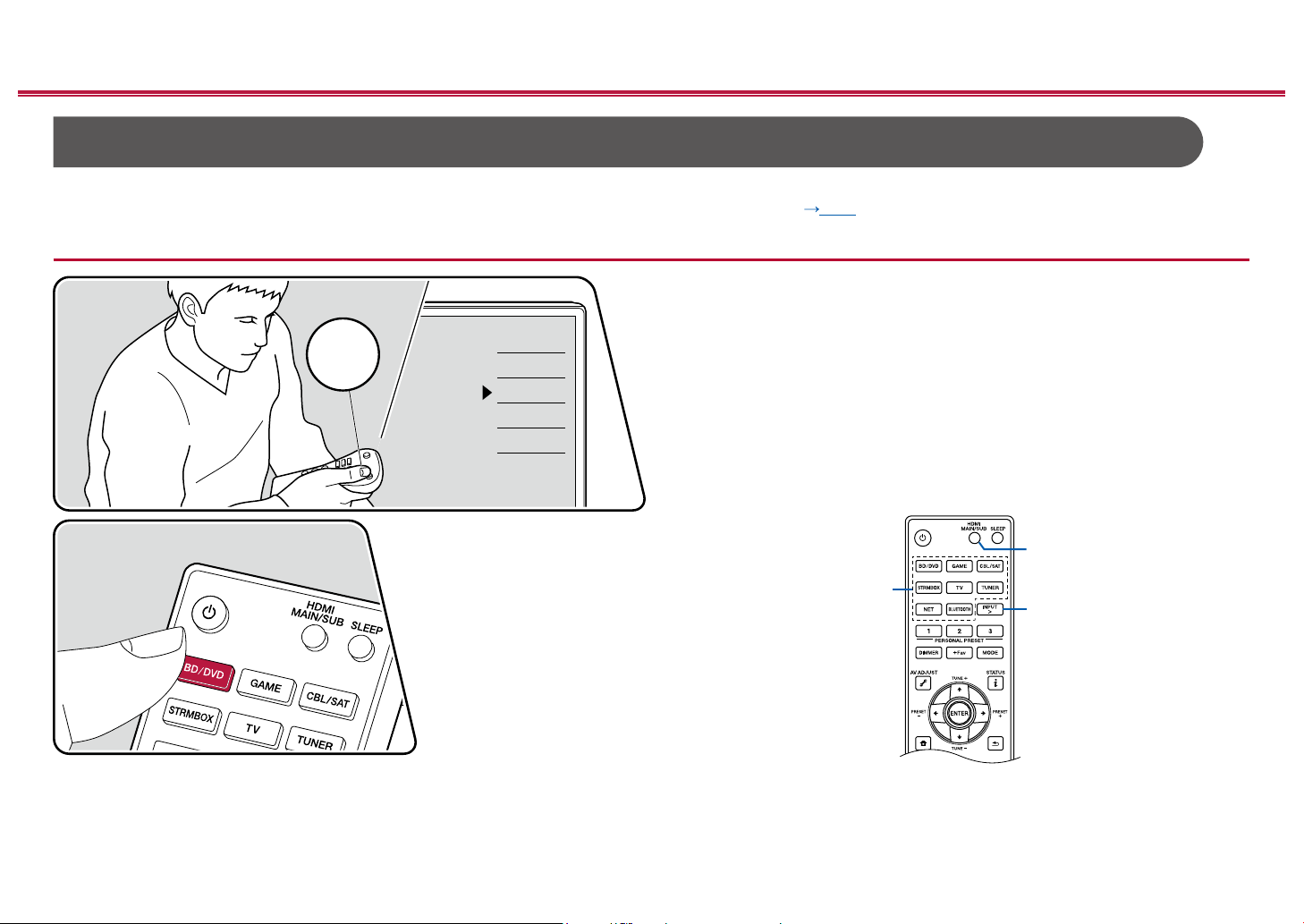
Contents ≫ Connections ≫ Playback ≫ Setup
TV
INPUT
AV Component Playback
You can play the audio from AV components, such as Blu-ray disc players through this unit.
• When a TV is connected to the HDMI OUT SUB jack, use the HDMI MAIN/SUB button or "AV Adjust" ( p196) to switch between MAIN and SUB.
Basic Operations
Perform the following procedure when this unit is on.
TV’s REMOTE
Inputs
TV
HDMI 1
HDMI 2
HDMI 3
1. Switch the input on the TV to the input connected to the unit.
2. Press the input selector whose name is the same as that of the jack to which
the player is connected.
For example, press BD/DVD to play the player connected to the BD/DVD jack.
Press TV to listen the sound of the TV. To play a device connected to the CD,
USB, PHONO, HDMI5, HDMI6 jack or the AUX INPUT HDMI jack on the front
panel, press INPUT > repeatedly to select the input.
• When the CEC link function works, the input switches automatically
when a CEC compliant TV or player is connected to this unit using HDMI
connection.
3. Start play on the AV component.
≫
HDMI MAIN/SUB
Input selector
INPUT >
95
Front Panel≫ Rear Panel≫ Remote≫
Page 96

Contents ≫ Connections ≫ Playback ≫ Setup
Pioneer SC-LX704XXX
BLUETOOTH® Playback
You can wirelessly play the audio on a BLUETOOTH-enabled device, such as a smartphone.
Basic Operations
Perform the following procedure when this unit is on.
Pairing
1. When you press the BLUETOOTH button, "Now Pairing..." is displayed on this
unit's display, and the pairing mode is enabled.
2. Enable (turn on) the BLUETOOTH function of the BLUETOOTH-enabled
device, and then select this unit from among the devices displayed. If a
password is requested, enter "0000".
• This unit is displayed as "Pioneer SC-LX704 XXXXXX". This display can be
• To connect another BLUETOOTH-enabled device, press and hold the
• The coverage area is approx. 48´/15 m. Note that connection is not always
≫
changed with the Friendly Name function ( p193) or the Pioneer Remote
App (can be used with the iOS or Android™).
BLUETOOTH button until "Now Pairing..." is displayed, and then perform
step 2. This unit can store the pairing information of up to 8 paired devices.
guaranteed with all BLUETOOTH-enabled devices.
Playing Back
1. Perform the connection procedure on the BLUETOOTH-enabled device.
2. Playing the music le.
The input on this unit automatically switches to "BLUETOOTH".
Turn up the volume of the BLUETOOTH-enabled device to an appropriate
level.
• Due to the characteristics of BLUETOOTH wireless technology, the sound
produced on this unit may slightly be behind the sound played on the
BLUETOOTH-enabled device.
96
Front Panel≫ Rear Panel≫ Remote≫
Page 97

Contents ≫ Connections ≫ Playback ≫ Setup
TV
INPUT
Network
Internet Radio
By connecting this unit to an Internet-connected network, you can enjoy Internet radio services, such as TuneIn Radio, etc.
• To play Internet radio services, the network needs to be connected to the Internet.
• Depending on the Internet radio service, a user registration may be required on your PC beforehand. For details of each service, visit the website of each service.
Playing Back
Perform the following procedure when this unit is on.
TV’s REMOTE
Inputs
TV
HDMI 1
HDMI 2
HDMI 3
1. Switch the input on the TV to the input connected to the unit.
2. Pressing NET will display the Network Functions list screen on the TV.
3. Select your preferred Internet radio service using cursor, and press ENTER to
conrm the selection.
4. Following the on-screen instructions, select a radio station and program using
cursor, and then press ENTER to play.
• To return to the previous screen, press
.
≫
NET
/ / /
ENTER
The illustration shows an image.
97
Front Panel≫ Rear Panel≫ Remote≫
Page 98

Contents ≫ Connections ≫ Playback ≫ Setup
Internet Radio Service Menu
You can bookmark specic stations, or delete stations that have been
bookmarked. The displayed menu varies according to the service being selected.
The menu icon is displayed while a station is being played. When only this
icon is displayed, pressing ENTER will display the menu on the screen. When
multiple icons are displayed, select the icon with the cursor, and press
ENTER.
Regarding the TuneIn Radio Account
If you create an account on the TuneIn Radio website (tunein.com), and log in it
from this unit, your favorite radio stations or programs you have followed on the
website are automatically added to your "My Presets" on this unit. "My Presets"
is displayed on the next level in the hierarchical structure of TuneIn Radio. To
display a radio station added to "My Presets", you need log into TuneIn Radio
from the unit. To log in, select "Login" - "I have a TuneIn account" in the "TuneIn
Radio" top list on the unit, and then enter your user name and password.
• If you select "Login" on this unit, a registration code is displayed. By using
this code, you can associate the device on the My Page section of the TuneIn
Radio website so that you can log in from "Login" - "Login with a registration
code" without entering the user name and password.
≫
98
Front Panel≫ Rear Panel≫ Remote≫
Page 99

Spotify
Use your phone, tablet or computer as a remote control for Spotify.
Go to spotify.com/connect to learn how.
Contents ≫ Connections ≫ Playback ≫ Setup
≫
99
Front Panel≫ Rear Panel≫ Remote≫
Page 100

Contents ≫ Connections ≫ Playback ≫ Setup
iPhone
Pioneer SC-LX704 XXXXXX
Wi-Fi
≫
AirPlay
By connecting this unit to the same network as iOS devices, such as iPhone®, iPod touch® and iPad®, you can enjoy music les on iOS devices wirelessly.
• Update the OS version on your iOS device to the latest version.
• Depending on the iOS version, operation screens or operation procedures on the iOS device may be different. For details, refer to the operating instructions for the
iOS device.
®
Playing Back on This Unit
1. Connect the iOS device to the access point where this unit is connected via
network.
2. Tap the AirPlay icon in the play screen of the music app on an iOS device
that supports Airplay and select this unit from the list of devices displayed.
3. Play the music le on the iOS device.
• If "System Setup" - "Hardware" - "Power Management" - "Network Standby" is
set to "Off " in the Home, manually turn the unit on and then press NET on the
remote controller. In the factory default setting, the Network Standby function (
p169) is set to On.
• Due to the characteristics of AirPlay wireless technology, the sound produced
on this unit may slightly be behind the sound played on the AirPlay-enabled
device.
You can also play the music les on a PC with iTunes (Ver. 10.2 or later)
equipped. Confirm that this unit and the PC are connected to the same network
beforehand. Then, press NET on the remote controller. Next, click the AirPlay
in iTunes, select this unit from the displayed devices, and start play of a
icon
music le.
e.g., iOS 10
100
Front Panel≫ Rear Panel≫ Remote≫
 Loading...