


DEH-X3600UI/XNUC
Pioneer DEH-X3600UI/XNUC, DEH-X3690UI/XNID, DEH-X3650UI/XNGS, DEH-X3650UI/XNGS1, DEH-X3650UI/XNCS Service Manual
...
PIONEER CORPORATION 1-1, Shin-ogura, Saiwai-ku, Kawasaki-shi, Kanagawa 212-0031, Japan
PIONEER ELECTRONICS (USA) INC. P.O. Box 1760, Long Beach, CA 90801-1760, U.S.A.
PIONEER EUROPE NV Haven 1087, Keetberglaan 1, 9120 Melsele, Belgium
PIONEER ELECTRONICS ASIACENTRE PTE. LTD. 253 Alexandra Road, #04-01, Singapore 159936
PIONEER CORPORATION 2013
CD RDS RECEIVER
ORDER NO.
CRT5370
DEH-X36UI/XNUC
DEH-X36UI
/XNUC
DEH-X3600UI/XNUC
DEH-X3650UI/XNCS
DEH-X3650UI/XNGS
DEH-X3650UI/XNGS1
DEH-X3690UI/XNID
This service manual should be used together with the following manual(s):
Model No. Order No. Mech. Module Remarks
CX-3287
CRT4759 S11.6STD CD Mech. Module : Circuit Descriptions, Mech. Descriptions, Disassembly
K-ZZZ JULY 2013 Printed in Japan
1234
1234
C
D
F
A
B
E
SAFETY INFORMATION
CAUTION
Where in a manufacturer’s service documentation, for example in circuit diagrams or lists
of components, a symbol is used to indicate that a specific component shall be replaced only
by the component specified in that documentation for safety reasons, the following symbol shall
be used:
This service manual is intended for qualified service technicians; it is not meant for the casual do-it-yourselfer.
Qualified technicians have the necessary test equipment and tools, and have been trained to properly and safely repair
complex products such as those covered by this manual.
Improperly performed repairs can adversely affect the safety and reliability of the product and may void the warranty.
If you are not qualified to perform the repair of this product properly and safely, you should not risk trying to do so
and refer the repair to a qualified service technician.
CAUTION:
USE OF CONTROLS OR ADJUSTMENTS OR PERFORMANCE OF PROCEDURES OTHER THAN THOSE
SPECIFIED HEREIN MAY RESULT IN HAZARDOUS RADIATION EXPOSURE.
- Safety Precautions for those who Service this Unit.
When checking or adjusting the emitting power of the laser diode exercise caution in order to get safe, reliable
results.
Caution:
1. During repair or tests, minimum distance of 13 cm from the focus lens must be kept.
2. During repair or tests, do not view laser beam for 10 seconds or longer.
WARNING
This product may contain a chemical known to the State of California to cause cancer, or birth defects or
other reproductive harm.
Health & Safety Code Section 25249.6 - Proposition 65
WARNING!
The AEL (accessible emission level )of the laser power output is less than CLASS 1
but the laser component is capable of emitting radiation exceeding the limit for
CLASS 1.
A specially instructed person should do servicing operation of the apparatus.
CAUTION
This product is a class 1 laser product classified under the Safety of laser products, IEC
60825-1:2007.
Laser diode characteristics
Wave length : 785 nm to 814 nm
Maximum output : 1 190 µW(Emitting period : unlimited)
Additional Laser Caution
Transistors Q101 in PCB drive the laser diodes.
When Q101 is shorted between their terminals, the laser diodes will radiate beam.
If the top cover is removed with no disc loaded while such short-circuit is continued,
the naked eyes may be exposed to the laser beam.
2
DEH-X36UI/XNUC

5 678
56
7
8
C
D
F
A
B
E
CAUTION
Danger of explosion if battery is incorrectly replaced.
Replaced only with the same or equivalent type recommended by the manufacturer.
Discord used batteries according to the manufacturer's instructions.
DEH-X36UI/XNUC
3

1234
1234
C
D
F
A
B
E
CONTENTS
SAFETY INFORMATION..................................................................................................................................... 2
1. SERVICE PRECAUTIONS............................................................................................................................... 5
1.1 SERVICE PRECAUTIONS ........................................................................................................................ 5
1.2 NOTES ON SOLDERING .......................................................................................................................... 5
2. SPECIFICATIONS............................................................................................................................................ 6
2.1 SPECIFICATIONS ..................................................................................................................................... 6
2.2 DISC/CONTENT FORMAT ........................................................................................................................ 9
3. BASIC ITEMS FOR SERVICE........................................................................................................................ 10
3.1 CHECK POINTS AFTER SERVICING..................................................................................................... 10
3.2 PCB LOCATIONS .................................................................................................................................... 10
3.3 JIGS LIST .................................................................................................................................................11
3.4 CLEANING................................................................................................................................................11
4. BLOCK DIAGRAM.......................................................................................................................................... 12
5. DIAGNOSIS.................................................................................................................................................... 14
5.1 OPERATIONAL FLOWCHART................................................................................................................ 14
5.2 ERROR CODE LIST ................................................................................................................................ 15
5.3 CONNECTOR FUNCTION DESCRIPTION............................................................................................. 18
6. SERVICE MODE ............................................................................................................................................ 19
6.1 DISPLAY TEST MODE 1 ......................................................................................................................... 19
6.2 DISPLAY TEST MODE 2 ......................................................................................................................... 20
6.3 SOFTWARE VERSION UP METHOD..................................................................................................... 21
6.4 CD TEST MODE...................................................................................................................................... 22
7. DISASSEMBLY .............................................................................................................................................. 23
8. EACH SETTING AND ADJUSTMENT ........................................................................................................... 29
8.1 CD ADJUSTMENT................................................................................................................................... 29
8.2 CHECKING THE GRATING AFTER CHANGING THE PICKUP UNIT.................................................... 30
8.3 PCL OUTPUT CONFIRMATION.............................................................................................................. 32
9. EXPLODED VIEWS AND PARTS LIST.......................................................................................................... 33
9.1 PACKING ................................................................................................................................................. 34
9.2 EXTERIOR............................................................................................................................................... 36
9.3 CD MECHANISM MODULE..................................................................................................................... 38
10. SCHEMATIC DIAGRAM............................................................................................................................... 40
10.1 TUNER AMP UNIT (GUIDE PAGE) ....................................................................................................... 40
10.2 KEYBOARD UNIT.................................................................................................................................. 46
10.3 CD CORE UNIT (S11.6VA) .................................................................................................................... 48
10.4 WAVEFORMS ........................................................................................................................................ 50
11. PCB CONNECTION DIAGRAM.................................................................................................................... 52
11.1 TUNER AMP UNIT................................................................................................................................. 52
11.2 KEYBOARD UNIT .................................................................................................................................. 56
11.3 CD CORE UNIT (S11.6VA) .................................................................................................................... 58
12. ELECTRICAL PARTS LIST .......................................................................................................................... 60
4
DEH-X36UI/XNUC

5 678
56
7
8
C
D
F
A
B
E
1. You should conform to the regulations governing the product (safety, radio and noise, and other
regulations), and should keep the safety during servicing by following the safety instructions
described in this manual.
2. Before disassembling the unit, be sure to turn off the power. Unplugging and plugging the connectors
during power-on mode may damage the ICs inside the unit.
3. To protect the pickup unit from electrostatic discharge during servicing, take an appropriate treatment
(shorting-solder) by referring to "the DISASSEMBLY".
4. After replacing the pickup unit, be sure to check the grating.
5. Be careful in handling ICs. Some ICs such as MOS type are so fragile that they can be damaged by
electrostatic induction.
6. Notes about installation and pin number description of Power IC (IC301: PA2032A)
The Power IC, PA2032A used on tha Tuner Amp Unit is a 25 pin IC.
The same PCB of the Tuner Amp Unit is used for other models that use a 27 pin IC, too.
So, the PCB has lands for a 27 pin IC.
When you replace the Power IC, install the Power IC onto 25 pins (2- 26 pin) located in the center of 27 pins for IC301.
Therefore, when you check the Power IC on the block diagram, the schematic diagram and the PCB connection
diagram, you have to pay attention as follows.
BLOCK DIAGRAM SCHEMATIC DIAGRAM
The pin number of left side is a number
on the PCB (silk printing).
The pin number of right side (in the IC frame)
means the pin number of IC itself.
The pin number is a number on the PCB
(silk printing).
The number in parentheses means the
pin number of IC itself.
10 (9)
8 (7)
6 (5)
4 (3)
26 (25)
H-SW
12 (11)
13 (12)
23 (22)
2 (1)
OFF.DET
No connection
1
2
3
4
5
6
7
8
9
10
11
12
13
14
15
16
17
18
19
20
21
22
23
24
25
No connection
For environmental protection, lead-free solder is used on the printed circuit boards mounted in this unit.
Be sure to use lead-free solder and a soldering iron that can meet specifications for use with lead-free solders for repairs
accompanied by reworking of soldering.
Compared with conventional eutectic solders, lead-free solders have higher melting points, by approximately 40 C.
Therefore, for lead-free soldering, the tip temperature of a soldering iron must be set to around 373 C in general, although
the temperature depends on the heat capacity of the PC board on which reworking is required and the weight of the tip of
the soldering iron.
Compared with eutectic solders, lead-free solders have higher bond strengths but slower wetting times and higher melting
temperatures (hard to melt/easy to harden).
The following lead-free solders are available as service parts:
Parts numbers of lead-free solder:
GYP1006 1.0 in dia.
GYP1007 0.6 in dia.
GYP1008 0.3 in dia.
1. SERVICE PRECAUTIONS
1.1 SERVICE PRECAUTIONS
1.2 NOTES ON SOLDERING
DEH-X36UI/XNUC
5

1234
1234
C
D
F
A
B
E
2. SPECIFICATIONS
DEH-X36UI/XNUC, DEH-X3600UI/XNUC
Securing the front panel
The front panel can be secured with the supplied screw.
Screw
(BPZ20P060FTC) (UC)
(XXX7020) (Except UC)
General
Power source ...................14.4 V DC (10.8 V to 15.1 V al-
lowable)
Grounding system ............Negative type
Maximum current consumption
..................................10.0 A
Dimensions (W × H × D):
DIN
Chassis ............................ 178mm × 50 mm × 165 mm
(7 in. × 2 in. × 6-1/2 in.)
Nose ................................ 188mm × 58mm × 15 mm
(7-3/8 in.× 2-1/4 in.× 5/8 in.)
D
Chassis ............................ 178mm × 50 mm × 165 mm
(7 in.× 2 in.× 6-1/2 in.)
Nose ................................ 170mm × 46mm × 15 mm
(6-3/4 in.× 1-3/4 in.× 5/8 in.)
Weight ............................. 1kg (2.2lbs)
Audio
Maximum power output ... 50 W × 4
70 W × 1/2 Ω (for subwoofer)
Continuous power output
................................... 22W × 4 (50Hz to 15 000Hz,
5 % THD, 4 Ω load, both chan-
nels driven)
Load impedance .............. 4 Ω (4 Ω to 8 Ω allowable)
Preout maximum output level
................................... 2.0 V
Loudness contour ............ +10dB (100Hz), +6.5 dB
(10 kHz) (volume: –30 dB)
Equalizer (5-Band Graphic Equalizer):
Frequency........................ 80 Hz/250 Hz/800 Hz/2.5kHz/
8 kHz
Equalization range ........... ±12 dB (2 dB step)
Subwoofer (mono):
Frequency........................ 50 Hz/63 Hz/80 Hz/100Hz/
125 Hz/160 Hz/200 Hz
Slope ...............................–12 dB/oct, –24 dB/oct
Gain ................................ +6 dB to –24dB
Phase .............................. Normal/Reverse
CD player
System ............................Compact disc audio system
Usable discs .................... Compact disc
Signal-to-noise ratio ......... 94 dB (1 kHz) (IHF-A network)
Number of channels ........ 2 (stereo)
MP3 decoding format ...... MPEG-1 & 2 Audio Layer 3
WMA decoding format ..... Ver. 7, 7.1, 8, 9, 10, 11, 12 (2 ch
audio)
(Windows Media Player)
WAV signal format ........... Linear PCM & MS ADPCM
(Non-compressed)
USB
USB standard specification
................................... USB 2.0 full speed
Maximum current supply
................................... 1A
USB Class ....................... MSC (Mass Storage Class)
File system....................... FAT12, FAT16, FAT32
MP3 decoding format ...... MPEG-1 & 2 Audio Layer 3
WMA decoding format ..... Ver. 7, 7.1, 8, 9, 10, 11, 12 (2 ch
audio)
(Windows Media Player)
WAV signal format ........... Linear PCM & MS ADPCM
(Non-compressed)
FM tuner
Frequency range .............. 87.9 MHz to 107.9 MHz
Usable sensitivity ............. 9dBf (0.8µV/75 Ω, mono, S/N:
30 dB)
Signal-to-noise ratio ......... 72 dB (IHF-A network)
AM tuner
Frequency range .............. 530 kHz to 1 710 kHz
Usable sensitivity ............. 25µV (S/N: 20 dB)
Signal-to-noise ratio ......... 62dB (IHF-A network)
CEA2006 Specifications
Power output ................... 14 W RMS × 4 Channels (4 Ω
and
1 % THD+N)
S/N ratio .......................... 91dBA (reference: 1W into
4 Ω)
Note
Specifications and the design are subject to
modifications without notice.
Backup current.................. 4.0 mA or less
2.1 SPECIFICATIONS
6
DEH-X36UI/XNUC

5 678
56
7
8
C
D
F
A
B
E
DEH-X3650UI/XNCS
General
Rated power source .........14.4 V DC
(allowable voltage range:
12.0 V to 14.4 V DC)
Grounding system ............Negative type
Maximum current consumption
..................................10.0 A
Dimensions (W × H × D):
DIN
Chassis ............................ 178mm × 50 mm × 165 mm
Nose ................................ 188mm × 58mm × 15 mm
D
Chassis ............................ 178mm × 50 mm × 165 mm
Nose ................................ 170mm × 46mm × 15 mm
Weight ............................. 1kg
Audio
Maximum power output ... 50 W × 4
70 W × 1/2 Ω (for subwoofer)
Continuous power output
................................... 22W × 4 (50Hz to 15 000Hz,
5 % THD, 4 Ω load, both chan-
nels driven)
Load impedance .............. 4 Ω (4 Ω to 8 Ω allowable)
Preout maximum output level
................................... 2.0 V
Loudness contour ............ +10dB (100Hz), +6.5dB
(10 kHz) (volume: –30 dB)
Equalizer (5-Band Graphic Equalizer):
Frequency........................ 80 Hz/250 Hz/800 Hz/2.5kHz/
8 kHz
Equalization range ........... ±12 dB (2 dB step)
Subwoofer (mono):
Frequency........................ 50 Hz/63 Hz/80 Hz/100Hz/
125 Hz/160 Hz/200 Hz
Slope ...............................–12 dB/oct, –24 dB/oct
Gain ................................ +6 dB to –24dB
Phase .............................. Normal/Reverse
CD player
System ............................Compact disc audio system
Usable discs .................... Compact disc
Signal-to-noise ratio ......... 94 dB (1 kHz) (IEC-A network)
Number of channels ........ 2 (stereo)
MP3 decoding format ...... MPEG-1 & 2 Audio Layer 3
WMA decoding format ..... Ver. 7, 7.1, 8, 9, 10, 11, 12 (2 ch
audio)
(Windows Media Player)
WAV signal format ........... Linear PCM & MS ADPCM
(Non-compressed)
USB
USB standard specification
................................... USB 2.0 full speed
Maximum current supply
................................... 1A
USB Class ....................... MSC (Mass Storage Class)
File system....................... FAT12, FAT16, FAT32
MP3 decoding format ...... MPEG-1 & 2 Audio Layer 3
WMA decoding format ..... Ver. 7, 7.1, 8, 9, 10, 11, 12 (2 ch
audio)
(Windows Media Player)
WAV signal format ........... Linear PCM & MS ADPCM
(Non-compressed)
FM tuner
Frequency range .............. 87.5 MHz to 108.0MHz
Usable sensitivity ............. 9dBf (0.8µV/75 Ω, mono, S/N:
30 dB)
Signal-to-noise ratio ......... 72dB (IEC-A network)
AM tuner
Frequency range .............. 531 kHz to 1602 kHz (9 kHz)
530 kHz to 1 640 kHz (10kHz)
Usable sensitivity ............. 25µV (S/N: 20 dB)
Signal-to-noise ratio ......... 62dB (IEC-A network)
Note
Specifications and the design are subject to
modifications without notice.
Backup current................. 4.0 mA or less
DEH-X36UI/XNUC
7

1234
1234
C
D
F
A
B
E
DEH-X3650UI/XNGS, DEH-X3650UI/XNGS1
General
Rated power source .........14.4 V DC
(allowable voltage range:
12.0 V to 14.4 V DC)
Grounding system ............Negative type
Maximum current consumption
..................................10.0 A
Dimensions (W × H × D):
DIN
Chassis ............................ 178mm × 50 mm × 165 mm
Nose ................................ 188mm × 58mm × 15 mm
D
Chassis ............................ 178mm × 50 mm × 165 mm
Nose ................................ 170mm × 46mm × 15 mm
Weight ............................. 1 kg
Audio
Maximum power output ... 50 W × 4
70 W × 1/2 Ω (for subwoofer)
Continuous power output
................................... 22W × 4 (50Hz to 15 000Hz,
5 % THD, 4 Ω load, both chan-
nels driven)
Load impedance .............. 4 Ω (4 Ω to 8 Ω allowable)
Preout maximum output level
................................... 2.0 V
Loudness contour ............ +10dB (100Hz), +6.5 dB
(10 kHz) (volume: –30 dB)
Equalizer (5-Band Graphic Equalizer):
Frequency........................ 80 Hz/250 Hz/800 Hz/2.5kHz/
8 kHz
Equalization range ........... ±12 dB (2 dB step)
Subwoofer (mono):
Frequency........................ 50 Hz/63 Hz/80 Hz/100Hz/
125 Hz/160 Hz/200 Hz
Slope ...............................–12 dB/oct, –24 dB/oct
Gain ................................ +6 dB to –24 dB
Phase .............................. Normal/Reverse
CD player
System ............................Compact disc audio system
Usable discs .................... Compact disc
Signal-to-noise ratio ......... 94dB (1 kHz) (IEC-A network)
Number of channels ........ 2 (stereo)
MP3 decoding format ...... MPEG-1 & 2 Audio Layer 3
WMA decoding format ..... Ver. 7, 7.1, 8, 9, 10, 11, 12 (2 ch
audio)
(Windows Media Player)
WAV signal format ........... Linear PCM & MS ADPCM
(Non-compressed)
USB
USB standard specification
................................... USB 2.0 full speed
Maximum current supply
................................... 1A
USB Class ....................... MSC (Mass Storage Class)
File system....................... FAT12, FAT16, FAT32
MP3 decoding format ...... MPEG-1 & 2 Audio Layer 3
WMA decoding format ..... Ver. 7, 7.1, 8, 9, 10, 11, 12 (2 ch
audio)
(Windows Media Player)
WAV signal format ........... Linear PCM & MS ADPCM
(Non-compressed)
FM tuner
Frequency range .............. 87.5 MHz to 108.0MHz
Usable sensitivity ............. 9dBf (0.8µV/75 Ω, mono, S/N:
30 dB)
Signal-to-noise ratio ......... 72dB (IEC-A network)
MW tuner
Frequency range .............. 531 kHz to 1602 kHz (9 kHz)
530 kHz to 1 640 kHz (10kHz)
Usable sensitivity ............. 25µV (S/N: 20 dB)
Signal-to-noise ratio ......... 62dB (IEC-A network)
SW tuner
Frequency range .............. 2300kHz to 7735kHz
(2 300 kHz to 2 495kHz,
2 940 kHz to 4 215kHz,
4 540 kHz to 5 175kHz,
5 820 kHz to 6 455kHz,
7 100 kHz to 7 735kHz)
9 500 kHz to 21 975 kHz
(9 500 kHz to 10 135kHz,
11 580 kHz to 12 215 kHz,
13 570 kHz to 13 870 kHz,
15 100 kHz to 15 735 kHz,
17 500 kHz to 17 985 kHz,
18 015 kHz to 18 135 kHz,
21 340 kHz to 21 975 kHz)
Usable sensitivity ............. 28µV (S/N: 20 dB)
Signal-to-noise ratio ......... 62 dB (IEC-A network)
Note
Specifications and the design are subject to
modifications without notice.
Backup current.................. 4.0 mA or less
8
DEH-X36UI/XNUC

5 678
56
7
8
C
D
F
A
B
E
DEH-X3690UI/XNID
General
Rated power source .........14.4 V DC
(allowable voltage range:
12.0 V to 14.4 V DC)
Grounding system ............Negative type
Maximum current consumption
..................................10.0 A
Dimensions (W × H × D):
DIN
Chassis ............................ 178mm × 50 mm × 165 mm
Nose ................................ 188mm × 58mm × 15 mm
D
Chassis ............................ 178mm × 50 mm × 165 mm
Nose ................................ 170mm × 46mm × 15 mm
Weight ............................. 1 kg
Audio
Maximum power output ... 50 W × 4
70 W × 1/2 Ω (for subwoofer)
Continuous power output
................................... 22W × 4 (50Hz to 15 000Hz,
5 % THD, 4 Ω load, both chan-
nels driven)
Load impedance .............. 4 Ω (4 Ω to 8 Ω allowable)
Preout maximum output level
................................... 2.0 V
Loudness contour ............ +10dB (100Hz), +6.5dB
(10 kHz) (volume: –30 dB)
Equalizer (5-Band Graphic Equalizer):
Frequency........................ 80 Hz/250 Hz/800 Hz/2.5kHz/
8 kHz
Equalization range ........... ±12 dB (2 dB step)
Subwoofer (mono):
Frequency........................ 50 Hz/63 Hz/80 Hz/100Hz/
125 Hz/160 Hz/200 Hz
Slope ...............................–12 dB/oct, –24 dB/oct
Gain ................................ +6 dB to –24 dB
Phase .............................. Normal/Reverse
CD player
System ............................Compact disc audio system
Usable discs .................... Compact disc
Signal-to-noise ratio ......... 94dB (1 kHz) (IEC-A network)
Number of channels ........ 2 (stereo)
MP3 decoding format ...... MPEG-1 & 2 Audio Layer 3
WMA decoding format ..... Ver. 7, 7.1, 8, 9, 10, 11, 12 (2 ch
audio)
(Windows Media Player)
WAV signal format ........... Linear PCM & MS ADPCM
(Non-compressed)
USB
USB standard specification
................................... USB 2.0 full speed
Maximum current supply
................................... 1A
USB Class ....................... MSC (Mass Storage Class)
File system....................... FAT12, FAT16, FAT32
MP3 decoding format ...... MPEG-1 & 2 Audio Layer 3
WMA decoding format ..... Ver. 7, 7.1, 8, 9, 10, 11, 12 (2 ch
audio)
(Windows Media Player)
WAV signal format ........... Linear PCM & MS ADPCM
(Non-compressed)
FM tuner
Frequency range .............. 87.5 MHz to 108.0MHz
Usable sensitivity ............. 9dBf (0.8 µV/75 Ω, mono, S/N:
30 dB)
Signal-to-noise ratio ......... 72dB (IEC-A network)
MW tuner
Frequency range .............. 531 kHz to 1602 kHz (9 kHz)
530 kHz to 1 640 kHz (10kHz)
Usable sensitivity ............. 25µV (S/N: 20 dB)
Signal-to-noise ratio ......... 62dB (IEC-A network)
SW tuner
Frequency range .............. 2300kHz to 7735kHz
(2 300 kHz to 2 495kHz,
2 940 kHz to 4 215kHz,
4 540 kHz to 5 175kHz,
5 820 kHz to 6 455kHz,
7 100 kHz to 7 735kHz)
9 500 kHz to 21 975 kHz
(9 500 kHz to 10 135kHz,
11 580 kHz to 12 215 kHz,
13 570 kHz to 13 870 kHz,
15 100 kHz to 15 735 kHz,
17 500 kHz to 17 985 kHz,
18 015 kHz to 18 135 kHz,
21 340 kHz to 21 975 kHz)
Usable sensitivity ............. 28µV (S/N: 20 dB)
Signal-to-noise ratio ......... 62 dB (IEC-A network)
Note
Specifications and the design are subject to
modifications without notice.
Backup current.................. 4.0 mA or less
2.2 DISC/CONTENT FORMAT
DEH-X36UI/XNUC
9
1234
1234
C
D
F
A
B
E
3. BASIC ITEMS FOR SERVICE
demrifnocebotmetIserudecorP.oN
1 Confirm whether the customer complain has
been solved.
If the customer complain occurs with the
specific media, use it for the operation check.
The customer complain must not be
reappeared.
Display, audio and operations must be
normal.
2 CD Play back a CD.
(Track search)
No malfunction on display, audio and
operation.
3 FM/AM tuner Check FM/AM tuner action.
(Seek, Preset)
Switch band to check both FM and AM.
Display, audio and operations must be
normal.
4 Check whether no disc is inside the product. The media used for the operating check must
be ejected.
retfaecnaraeppastinotridrosehctarcsoNkcehcecnaraeppA5
receiving it for service.
Item to be checked regarding audio
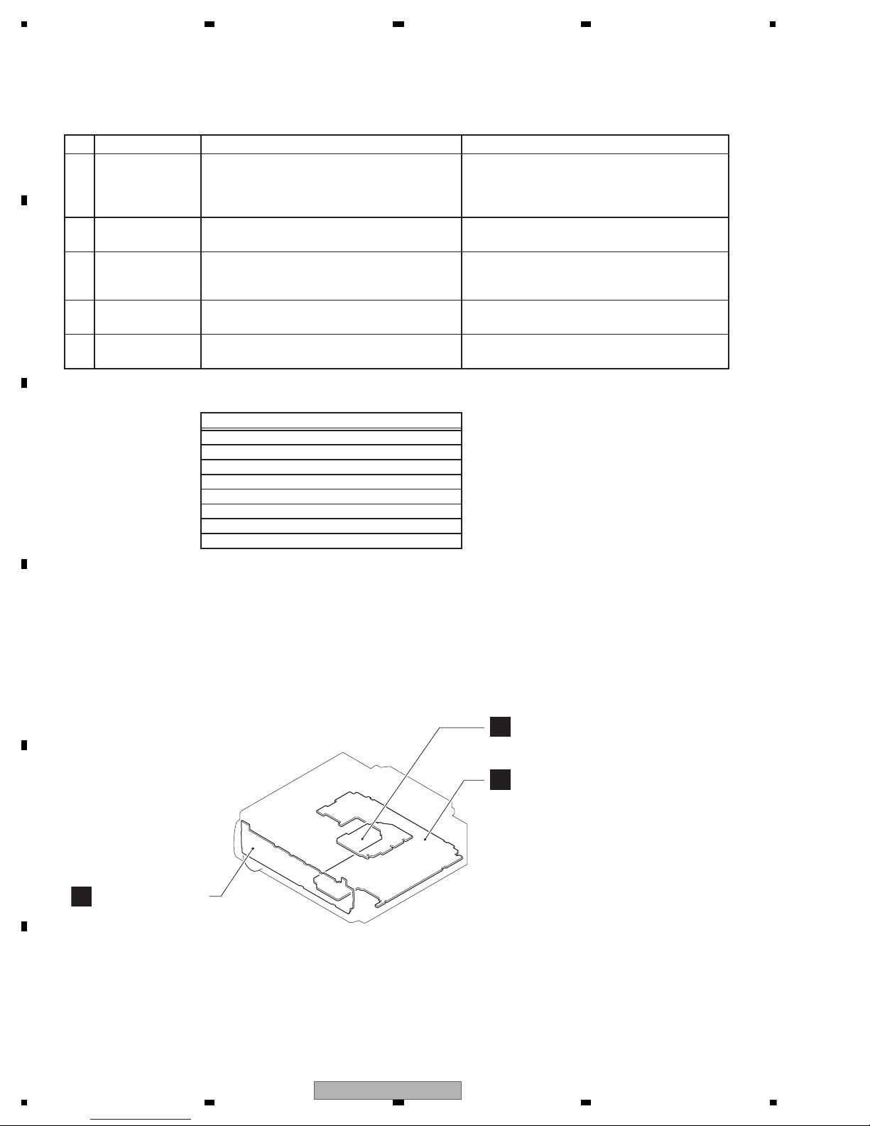
A
B
Keyboard Unit
Tuner Amp Unit
C
CD Core Unit (S11.6VA)
A:DEH-X36UI/XNUC
B:DEH-X3600UI/XNUC
C:DEH-X3650UI/XNCS
E:DEH-X3650UI/XNGS
F:DEH-X3650UI/XNGS1
G:DEH-X3690UI/XNID
Unit Number : QWM3628(A,B)
Unit Number : QWM3629(C)
Unit Number : QWM3630(E,F)
Unit Number : QWM3631(G)
Unit Name : Tuner Amp Unit
Unit Number :
Unit Name : Keyboard Unit
Unit Number : CWX4269
Unit Name : CD Core Unit(S11.6VA)
3.1 CHECK POINTS AFTER SERVICING
To keep the product quality after servicing, please confirm following check points.
See the table below for the items to be checked regarding audio:
Distortion
Noise
Volume too low
Volume too high
Volume fluctuating
Sound interrupted
3.2 PCB LOCATIONS
10
DEH-X36UI/XNUC
5 678
56
7
8
C
D
F
A
B
E
- Jigs List
- Grease List
Name
Grease
Grease
Grease No.
GEM1024
GEM1043
Remarks
CD Mechanism Module
CD Mechanism Module
N
G
Name
16P FFC
Test Disc
L.P.F.
Jig No.
GGD1310
TCD-782
Remarks
Tuner Amp Unit - CD Core Unit
Checking the grating
Checking the grating (Two pieces)
Before shipping out the product, be sure to clean the
following portions by using the prescribed cleaning
tools:
Portions to be cleaned Cleaning tools
CD pickup lenses Cleaning liquid : GEM1004
Cleaning paper : GED-008
3.3 JIGS LIST
ame
3.4 CLEANING
rease No.
emarks
DEH-X36UI/XNUC
11
1234
1234
C
D
F
A
B
E
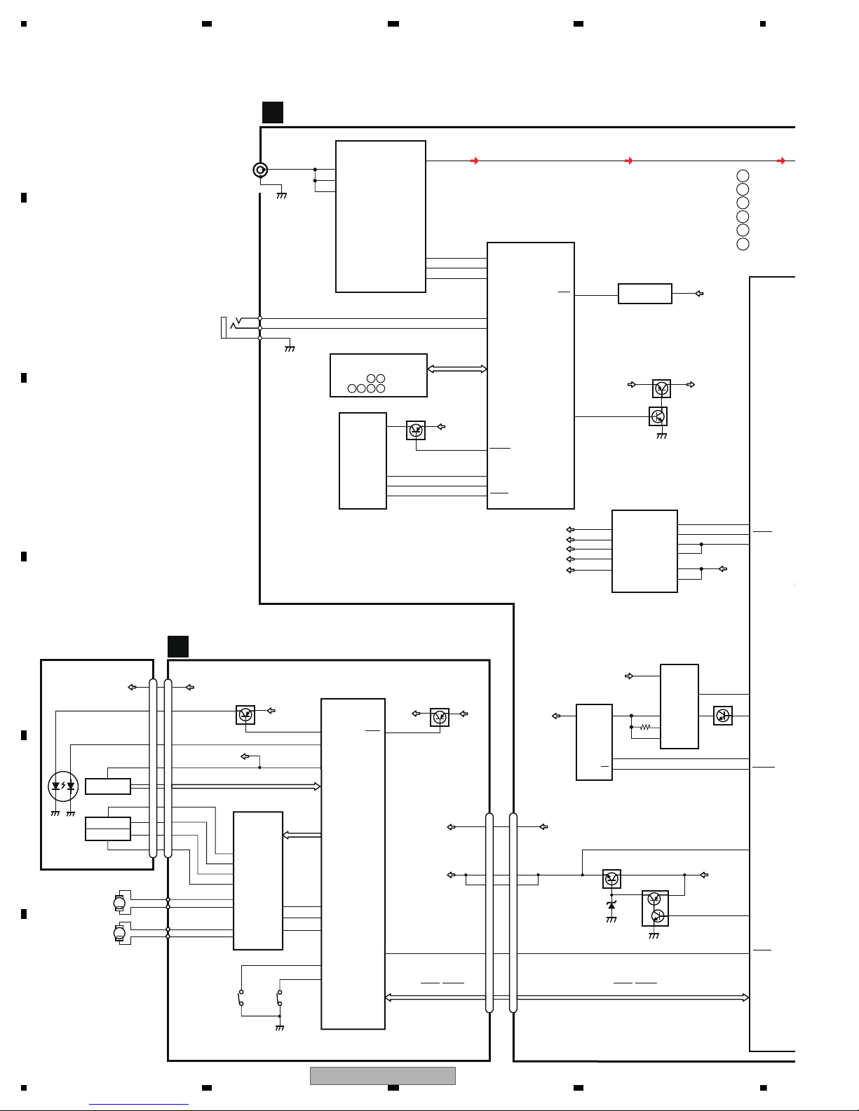
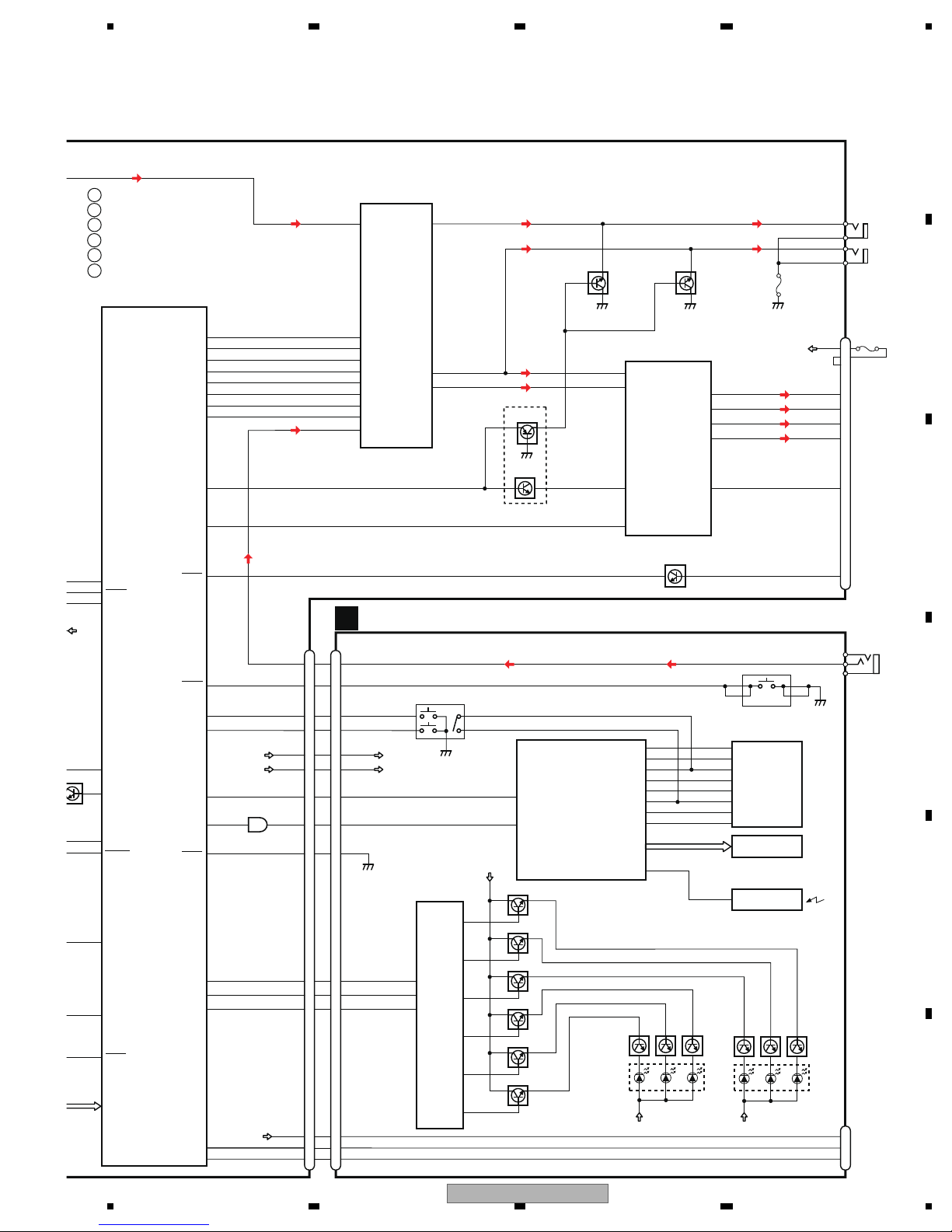
4. BLOCK DIAGRAM
JA401
1
2,3
CN701
ANTENNA
ILMPW
19
VDD3.3V
9
CDRST
8
RESET 33
DDON
SYNC
USBCTL
USBFLG
B.UP
Q751
2
1
Q752
VDCONT
85
VDSENS
55
MECHA VD
VD
VDD
SYSTEM
COMP
(2
IC6
R5S726A
FM/AM TUNER
IC401
TDA7706
5
FMMIXIN1
16
PINDIN
18
LNAIN
SYSTEM MICRO
COMPUTER
(1/2)
IC601
R5S726A0D216FP
TUN_SDA
TUN_SCL
33
34
57
94
93
TUNRES
31
88
I2CSDA
RSTN
I2CSCL
DACOUTL
FLASH ROM
IC681
CD DATA (CDSRQ,CDSTBY,SKIP,
SCL,SDA,DATA,BCLK,LRCK,WAIT)
TUNER AMP UNIT
A
6
8
91
25
92
724
2
SCL
RST
VCC
SDA
iPod CP
IC531
337S3959
VDD3.3V
Q531
CP_SCL
CP_SDA
CPPWR
CPRST
ILMPW
B.UP
ILM+B
Q872
Q871
CD CORE UNIT(S11.6 VA)
M
LD
MD
SPINDLE
M
LOADING/CARRIAGE
LD+
MD
10
11
HOLOGRAM
RF AMP, CD DECODER
2
VD
VD
9
3
SPO+
2
SPO-
5
SLLDO+
4
SLLDO-
22
LDIN
21
MUTE
TD,FD
AC,BD,VC,E,F
SD,MD
1
LD
2
PD
CONT
LOEJ
HOME
35
41
39
VDD
1
VDD
VDD
10
11
FOCUS ACT.
TRACKING ACT.
FOP
TOP
2
1
TOP
FOP
7
TKO-
10
FCO+
2
1
DSCSNS
38
29
RESET
8
RESET
88
VREF
REFO
93
REFOUT
3
3
FOM
FOM
8
TKO+
4
4
TOM
TOM
9
FCO-
23
CNT
CLCONT
40
54
PUEN
V+3A
VDD
UNIT
MOTOR
MOTOR
ACTUATOR/
MOTOR DRIVER
BD8223EFV
HOMEDSCSNS
PEQ094A
DIGITAL SERVO/DATA • PROCESSOR
CPU
CN701
Q101
CN101
Q102
IC301
S901
S903
IC201
C
V+3A
7
7
VCC
PD
REFO
SOP
SOM
LCOP
LCOM
PICKUP UNIT
(P11)(SERVICE)
LD
CD DATA (CDSRQ,CDSTBY,SKIP,
SCL,SDA,DATA,BCLK,LRCK,WAIT)
JA891
2
3
1
WIRED
REMOTE
KEYAD
KEYD
GND
KEYAD
56
KEYD
105
RES
139
RESET
IC671
S-80827CNMC-B8M
OUT
2
VDD
VDD3.3V
SWVDD
SW5V
9
6
BSENS
SYSPW
SWVDD
1
11
90
113
8
3
2
B.UP
4
10
SYS+B
SWVDD
VDD12
SW5V
SYS+B
BSENS
SW5VCNT
+B
+BUP
VDDCONT
SYSPW
5
REGULATOR IC
IC911
BA49183-V12
VDD1.2V
VDD3.3V
VDD
8
7
VCC
EN
VIN
EN
OC
USB5V
VOUT
5
SYNC
1185
986
1
8
119
1
3
1204
B.UP
BD9876EFJ
IC551
BD2232G-G
IC552
USB5V REGULATOR
FB
LX
4
BST
7
Q601
:DEH-X3
:DEH-X3
E
:DEH-X3
G
:DEH-X3
F
:DEH-X3
A
B
:DEH-X3
C
:PEB106A8
:PEB103A8
A
CEFBG
12
DEH-X36UI/XNUC
5 678
56
7
8
C
D
F
A
B
E
USB
USB5V
DM
DP
11
13
15
2
3
4
USB5V
DM
DP
CN1911
KEY MATRIX
4
6
2
1
5
4
4
3
2
1
3
AUXL
SOURCE
ROT0
ROT1
KDT2
KST1
18
19
LCD DRIVER/
KEY CONTROLLER
MULTI-CONTROL
PDC202B
LCD
98
RMIN/P73/INT/T0IN
93
P03
92
P02
91
P01
90
P00
97
P07
96
P06
95
P05
94
P04
KST3
KST2
KST1
KST0
KDT3
KDT2
KDT1
KDT0
CN1931
S1830
IC1802
V1802
S1842
JA1921
FRONT AUX
AUXL
AUXGND 1
2
AUXR 3
RGBDT
RGBST
RGBCK
7
14
12
RGB DRIVER
IC1851
BH2228FV
BLUE Key
10
12
CSB
11
CLK
DI
1
AO1
ILM+B
6
AO6
5
AO5
4
AO4
Q1852(1/2)
Q1853(1/2)
Q1853(2/2)
Q1851(1/2)
Q1851(2/2)
Q1852(2/2)
2
AO2
3
AO3
GREEN Key
RED Key
RED LCD
GREEN LCD
BLUE LCD
Q1859
D1882,
Q1858 Q1857 Q1868
D1885,
D1886
Q1867 Q1866
ILM+B ILM+B
PNJ4833M
SENSOR
REMOTE CONTROL
IC1941
1
KYDT
DPDT
10
8
100
99
URX/P35
UTX/P34
3
DSENS
20
SWVDD
5
ILM+B
KEYBOARD UNIT
B
D1883,
D1884
B.UP
117
17
MUTE
ANTPW
89
ASENS
FL-
FL+
RL-
RL+
FL-
FL+
RL-
RL+
ACC
Q941
MUTE
OFF.DET
CN801
ASENS
13
7
5
1
3
18
JA901
18
10
8
SOURCE
DPDT
KYDT
SSENS
35
ROT0
53
ROT1
54
DPDT
23
KYDT
22
FLIn
20
DSENS
DSENS
34
DM
49
DP
50
RLIn
MUTE
CDRST
33
DDON
5
AUXL
19
SYNC
USBCTL
USBFLG
VDCONT
85
VDSENS
55
SYSTEM MICRO
COMPUTER
(2/2)
IC601
R5S726A0D216FP
POWER AMP
IC301
PA2032A
Q301
(1/2)
Q301
(2/2)
Q252 Q251
INAN1L
40
33
OUTFL
34
OUTRL
35
OUTPL
ELECTRONIC VOLUME/
SOURCE SELECTOR
IC201
PM9013A
37
INBP4L
MCLK
LRCLK
BCLK
DIN
DATA
RESETB
CLK
STB
EVOL_RST
EVOL_CK
EVOL_DT
EVOL_DATA
EVOL_BCK
EVOL_LRCK
EVOL_MCK
EVOL_CS
19
20
21
22
23
26
24
25
81
104
103
106
110
87
108
111
11
USB5V
4
6
ROT0
ROT1
DM
DP
13
15
42
IC801
TC7SET08FUS1
ILM+B
3
SWVDD
TUNL
AUXL
PREOUT
POWER SUPPLY
JA251
P251
FL
PL
RCAG
6
3
14RCAG
PL
FL
RGBCS/ILMCLR2
RGBCK/ILMCLR1
RGBST/ILMCLR2
RGBCK/ILMCLR1
15
11
14
RGBDT/DIMMER
RGBDT
21
7
12
BREM
H-SW
14
BSENS
SYSPW
SWVDD
90
113
8
B.UP
118
98
119
120
:DEH-X36UI/XNUC
:DEH-X3650UI/XNGS
E
:DEH-X3690UI/XNID
G
:DEH-X3650UI/XNGS1
F
:DEH-X3600UI/XNUC
A
B
:DEH-X3650UI/XNCS
C
SORUCE
10(9)
8(7)
4(3)
6(5)
23(22)
2(1)
12(11)
13(12)
26(25)
15
B.UP
17
FUSE 10A
DEH-X36UI/XNUC
13
1234
1234
C
D
F
A
B
E
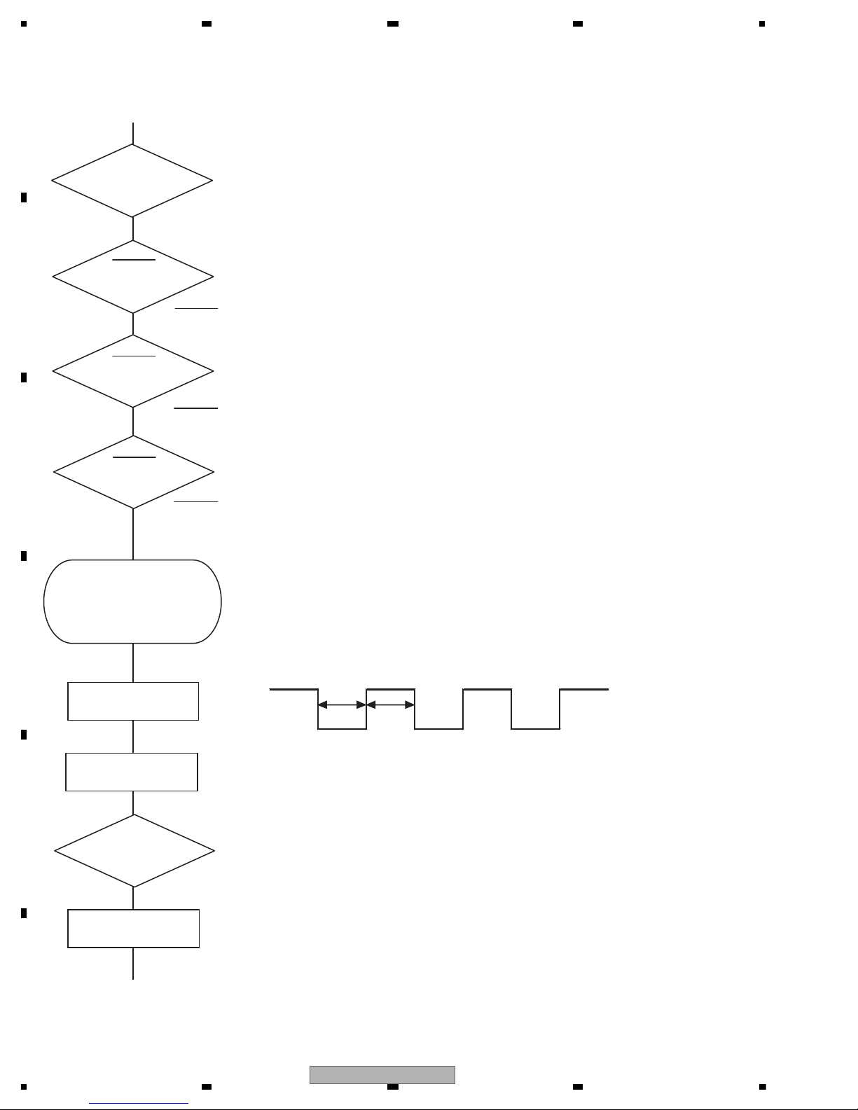
5. DIAGNOSIS
Vcc = 1.2 V
PVcc = 3.3 V
BSENS
Pin 90
ASENS
Pin 89
DSENS
Pin 34
BSENS = L
DSENS = L
Starts
communication
with Grille
microcomputer.
SWVDD <- H
Pin 113
Source keys
operative
Source ON
SYSPW <- H
Pin 8
300 ms
300 ms
In case of the above signal, the communication
with Grille microcomputer may fail.
If the time interval is not 300 msec, the oscillator
may be defective.
Completes power-on operation.
(After that, proceed to each source operation)
Power ON
ASENS = L
Vcc : Pin 12, 20, 43, 78, 86, 109
PVcc : Pin 3, 16, 28, 36, 48, 69, 82,101, 112
5.1 OPERATIONAL FLOWCHART
14
DEH-X36UI/XNUC
5 678
56
7
8
C
D
F
A
B
E
8-digit display 6-digit display 4-digit display
ERROR-xx ERR-xx E-xx
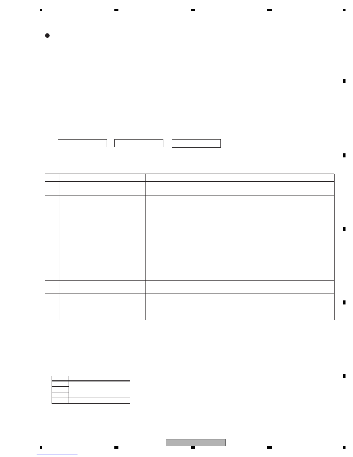
(2) LIST OF CD ERROR CODES (Error Mode: 0xFD)
Code Classification
Error code to be displayed
Details and possible causes
10 Servo Carriage Home NG The pickup cannot move toward the inner track.
The CRG cannot move from the inner track.
--> Defective HOME SW; Failure in CRG movement.
07 Servo TOC reading NG TOC information cannot be read.
--> The partial disk or TOC content is illegal.
11 Servo Focus NG Focusing not available
--> Disc placed upside-down; Stains on the disc; excessive vibration.
17 Servo Setup NG The laser output cannot be adjusted. Focus can be easily lost.
--> Scratches or stains on the disc; excessive vibration.
15 Servo RF NG The digital signal from the disc cannot be detected.
--> A CD-R/RW disc that does not contain data loaded.
12 Servo Spindle Lock NG
Subcode NG
RF-amp NG
Spindle not locked. Subcode not readable.
Proper RF AMP gain not obtained.
--> Defective spindle; Scratches or stains on the disc; excessive vibration.
-->
A CD-R/RW disc that does not contain data loaded, or in a rare case, disc placed upside-down.
--> RF signal error.
30 Servo Search Time Out Failed to reach a target address. And, the search became a timeout.
--> Carriage/Tracking error; Scratches on the disc; Stains on the disc
50 Mechanism Load NG
Eject NG
Disc loading/ejection not completed
--> A foreign object inserted in the mechanism; Disc jammed.
51 Mechanism Failure in retried
turning for ejection
Disc could not be ejected even after disc turning had been retried.
--> A foreign object inserted in the mechanism; Disc jammed.
ERROR CODES
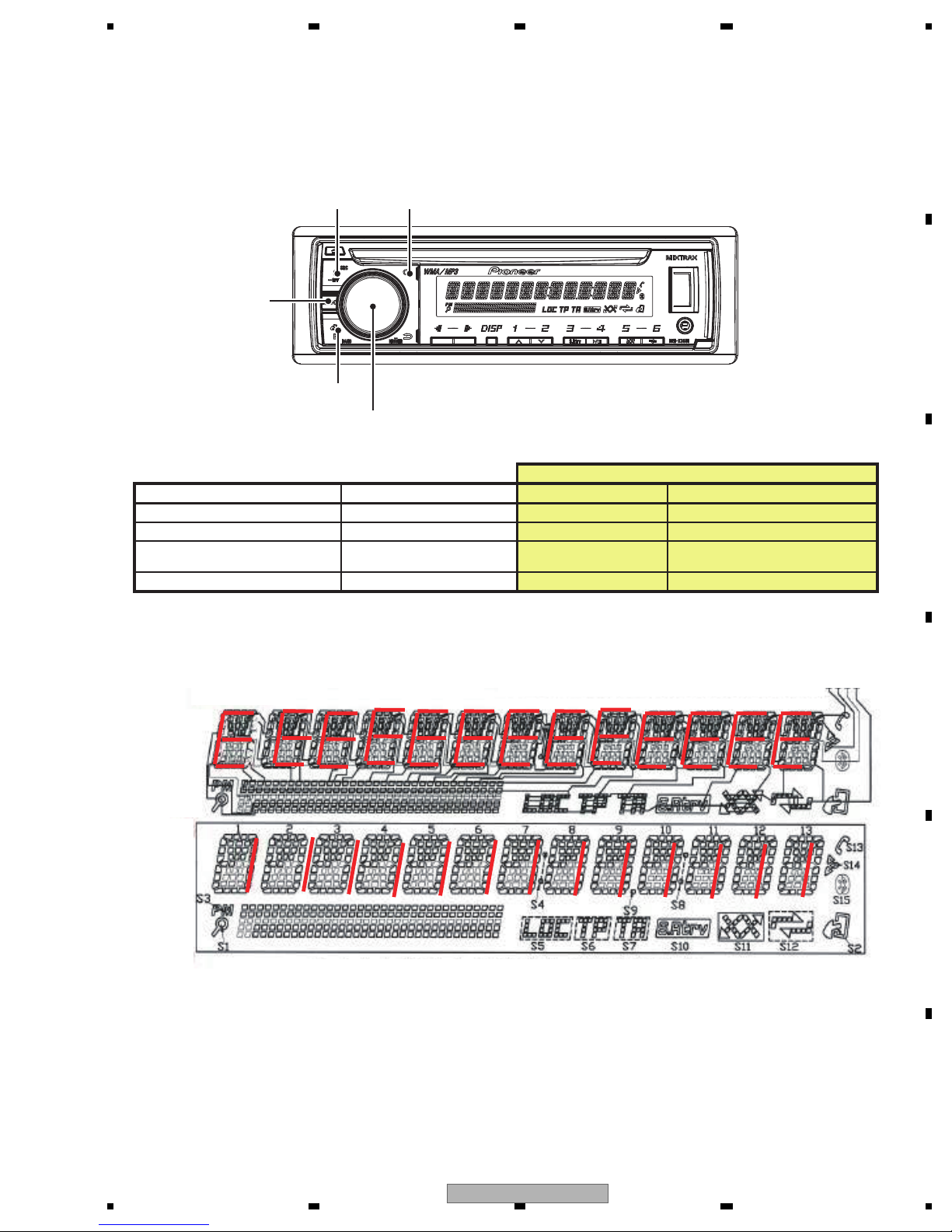
(1) DISPLAY METHOD
If “0xFD” error mode is displayed in CD MODE (CD MODE area for display), an error code will be displayed in the MIN (minute
display) and SEC (second display) areas.
The same code is displayed in the MIN and SEC areas.
The TNO area is blank (#0FFH), as it conventionally was.
• Display example of the head unit
Depending on the display capability of LCDs, the display format varies, as shown below. XX denotes an error number.
Note: In a case of an OEM product, the error display format is subject to the specifications used by the equipment
manufacturer.
If a CD memory device is inoperable, or operation of such media is stopped by an error, the error mode is established and a
cause of the error is displayed by an error code. Indication of error codes is intended to reduce the number of calls from
customers and facilitate failure analysis and repair work in servicing.
• The 2 high-order digits of an error code denote the main classification, shown below.
code classification
0x
1x Servo-related errors
3x
5x Mechanism-related errors
• How to restore from each error is shown below.
Servo-related errors(0X, 1X, 3X) : Servo-related errors CD Off, Eject, ACC Off, Back-up Off, Communication reset, Reset
Load NG/Eject NG(50) : Reload, Eject, ACC Off, Back-up Off, Communication reset, Reset
Failure in retried turning for ejection : CD On, Eject, ACC Off, Back-up Off, Communication reset, Reset
NOTES
• Indications of error codes are available only during disc operations, because CD operations are unavailable if a mechanical error is
generated.
• If the TOC cannot be read, It stops because of error 07.
• If you design a new head unit, be sure to use one of the display formats indicated in “Display example of the head unit.”
5.2 ERROR CODE LIST
DEH-X36UI/XNUC
15

1234
1234
C
D
F
A
B
E
Symptoms are written in bold and causes in regular, non-indented text. Regular, indented text is
used to indicate actions to be taken.
Common
AMP ERROR
This unit fails to operate or the speaker connection is
incorrect; the protective circuit is activated.
Check the speaker connection. If the message
fails to disappear even after the engine is
switched off/on, contact your dealer or an
authorized Pioneer Service Station for
assistance.
CD player
ERROR-07, 11, 12, 17, 30
The disc is dirty.
Clean the disc.
The disc is scratched.
Replace the disc.
ERROR-07, 10, 11, 12, 15, 17, 30, A0
There is an electrical or mechanical error.
Turn the ignition switch OFF and back ON, or
switch to a different source, then back to the CD
player.
ERROR-15
The inserted disc is blank.
Replace the disc.
ERROR-23
Unsupported CD format.
Replace the disc.
FORMAT READ
Sometimes there is a delay between the start of playback and when you start to hear any sound.
Wait until the message disappears and you hear
sound.
NO AUDIO
The inserted disc does not contain any playable files.
Replace the disc.
SKIPPED
The inserted disc contains DRM protected files.
The protected files are skipped.
PROTECT
All the files on the inserted disc are embedded with
DRM.
Replace the disc.
USB storage device/iPod
FORMAT READ
Sometimes there is a delay between the start of playback and when you start to hear any sound.
Wait until the message disappears and you hear
sound.
NO AUDIO
There are no songs.
Transfer the audio files to the USB storage device
and connect.
The connected USB storage device has security enabled.
Follow the USB storage device instructions to
disable the security.
SKIPPED
The connected USB storage device contains DRM
protected files.
The protected files are skipped.
PROTECT
All the files on the connected USB storage device
are embedded with DRM.
Replace the USB storage device.
N/A USB
The connected USB device is not supported by this
unit.
Connect a USB Mass Storage Class compliant
device.
Disconnect your device and replace it with a
compatible USB storage device.
CHECK USB
The USB connector or USB cable has shortcircuited.
Check that the USB connector or USB cable is
not caught in something or damaged.
CHECK USB
The connected USB storage device consumes more
than maximum allowable current.
Disconnect the USB storage device and do not
use it. Turn the ignition switch to OFF, then to
ACC or ON and then connect only compliant
USB storage devices.
CHECK USB
The iPod operates correctly but does not charge.
Make sure the connection cable for the iPod has
not shorted out (e.g., not caught in metal
objects). After checking, turn the ignition switch
OFF and back ON, or disconnect the iPod and
reconnect.
16
DEH-X36UI/XNUC

5 678
56
7
8
C
D
F
A
B
E
ERROR-19
Communication failed.
Perform one of the following operations.
–Turn the ignition switch OFF and back ON.
–Disconnect the USB storage device.
–Change to a different source.
Then, return to the USB source.
iPod failure.
Disconnect the cable from the iPod. Once the
iPod’s main menu is displayed, reconnect the
iPod and reset it.
ERROR-23
USB storage device was not formatted with FAT12,
FAT16 or FAT32.
USB storage device should be formatted with
FAT12, FAT16 or FAT32.
ERROR-16
The iPod firmware version is old.
Update the iPod version.
iPod failure.
Disconnect the cable from the iPod. Once the
iPod’s main menu is displayed, reconnect the
iPod and reset it.
STOP
There are no songs in the current list.
Select a list that contains songs.
NOT FOUND
No related songs.
Transfer songs to the iPod.
Pandora
ERROR-19
Communication failed.
Disconnect the cable from the device. Once the
device’s main menu is displayed, reconnect the
device and reset it.
START UP APP
The Pandora application has not started running yet.
Start up the Pandora application.
MAINTENANCE
Pandora system is undergoing maintenance.
Try again later.
INOPERABLE
The operation was disabled.
Run the same command for another track.
TRYAGAIN
Unable to save thumb rating.
Unable to save BookMark.
Unable to add station.
Try again later.
SKIP LIMIT
Skip limit reached.
Do not exceed the skip limit.
Due to music licensing restrictions, Pandora
limits the total number of skips per hour.
CHECK APP
This version of the Pandora application is not supported.
Connect a device that has a compatible version
of the Pandora application installed.
CHECK DEVICE
Device error message displayed in Pandora application.
Unable to play music from Pandora.
Please check your connected device.
NO STATION
No station found.
Create a station in the Pandora application on
your connected device.
NO ACTIVE ST
No station selected.
Select a station.
STATION FULL
A new station cannot be added.
Delete an old station to open a spot for a new
one.
CAN.T DELETE
The station could not be deleted.
Run the same command for another station.
NO NETWORK
The connected device is out of area.
Connect the connected device to a network.
NO SERVICE
The connected device is out of area.
Connect the connected device to a network.
CAN.T PLAY
The operation was disabled.
Run the same command for another station.
Apps
START UP APP
The application has not started running yet.
Follow the instructions that appear on the
screen.
DEH-X36UI/XNUC
17
1234
1234
C
D
F
A
B
E
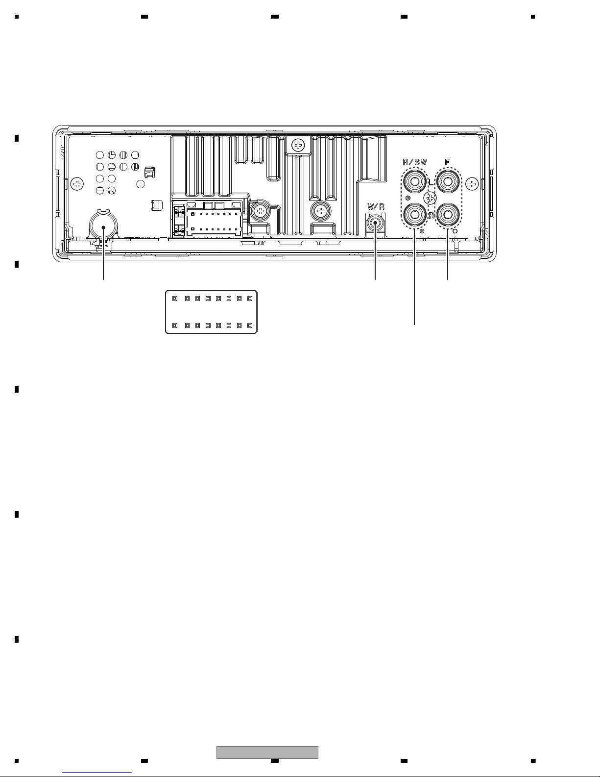
5.3 CONNECTOR FUNCTION DESCRIPTION
1 FL+
2 FR+
3 FL4 FR5 RL+
6 RR+
7 RL8 RR-
9 NC
10 NC
11 NC
12 NC
13 ACC
14 B.REM
15 B.UP
16 GND
16
14
12
10 8
6
42
15
13
11
97
5
31
WIRED
REMOTE
CONTROL
REAR OUTPUT or
SUBWOOFER OUTPUT
FRONT
OUTPUT
ANTENNA INPUT
18
DEH-X36UI/XNUC
5 678
56
7
8
C
D
F
A
B
E
Grille condition
Conf. item Operate Show LCD RGB
All light up
MIX + LIST
Draw 1 White
All light off SOURCE No light Draw2 No light
Conf. LCD pattern 1
(* And change ILM color)
BAND Draw 3
Red
Conf. LCD pattern 2
ROTARY center
Draw 4 Green
Drawings Style
Draw1 ALL light up
Draw2 ALL light off
Draw3
Draw4
BAND
SOURCE
MIX
LIST
ROTARY
Press and hold "MIX" and "LIST" buttons together, and turn BUP and ACC on.
[How to enter Test mode]
6. SERVICE MODE
6.1 DISPLAY TEST MODE 1
DEH-X36UI/XNUC
19
1234
1234
C
D
F
A
B
E
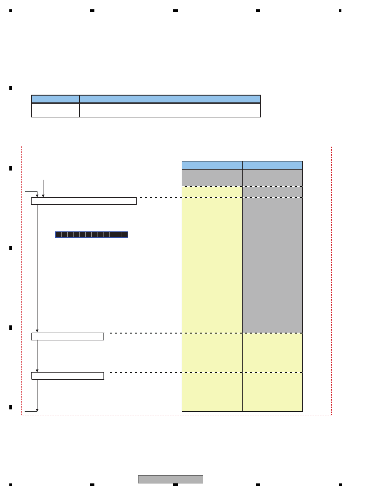
6.2 DISPLAY TEST MODE 2
* Initial
condition
$ PD number
For Ver.7.01, "701" is displayed
For PEA010A, "010A" is displayed
# System
microcomputer
version
S
$$$$
###
1 + 3
On (state when
entering test mode)
Press and hold "1" and "3" buttons together, and turn BUP and ACC on.
[Operation key]
[How to enter Test mode]
[Test items]
Start display test mode.
Press and hold "1" and "3" buttons together, and turn
BUP and ACC on.
Display is normally updated
Display update is stopped
Product operation is performed as usual, in appearance.
The screen gets still when entering this item.
On (an initial value)
On (lighting condition
of normal times)
On (an initial value or
setting value of default
menu)
On (an initial value or
setting value of default
menu)
On (an initial value or
setting value of default
menu)
Off
All off
All off
All off
Remarks
Key Illumination
Operation key Processing
Icon
Enter display test mode
Switch to next test mode
The information such as the system microcomputer version is checked.
Switching to next display
by pressing “ 1 ” + “ 3 ” buttons together.
Switching to next display
by pressing “ 1 ” + “ 3 ” buttons together.
Switching to next display
by pressing “ 1 ” + “ 3 ” buttons together.
System Version information is displayed.
20
DEH-X36UI/XNUC
 Loading...