

PIONEER AVIC 800 DVD Installation Manual [fr]
AVIC-900DVD
AVIC-800DVD
ENGLISH
MANUEL D’INSTALLATION
ESPAÑOL
DEUTSCH
FRANÇAIS
This product conforms to new cord colours.
Los colores de los cables de este producto se conforman con un nuevo código de colores.
Dieses Produkt entspricht den neuen kabelfarben.
Le code de couleur des câbles utilisé pour ce produit est
nouveau.
Questo prodotto è conforme ai nuovi codici colori.
De kleuren van de snoeren van dit toestel zijn gewijzigd.
INSTALLATION MANUAL
ITALIANO
NEDERLANDS

IMPORTANT INFORMATION
ABOUT YOUR NEW DVD NAVIGATION UNIT AND THIS MANUAL
• The Pioneer DVD Navigation Unit is intended solely as an aid to you in the operation of your vehicle. It is not a substitute for your attentiveness, judgement and
care while driving.
• Do not use your navigation system to route you to emergency services such as
hospitals or police stations. Not all emergency service facilities are contained in
the map data.
• Do not operate the DVD Navigation Unit if doing so will divert your attention
from the safe operation of your vehicle. Always observe safe driving rules and
follow all existing traffic regulations.
• This manual explains how to install this DVD Navigation Unit in your vehicle.
Operation of this DVD Navigation Unit is explained in the separate “Operation
Manual” or “Hardware Manual” that also came with this unit.
1

Contents
IMPORTANT SAFEGUARDS .................... 3
PLEASE READ ALL OF THESE
INSTRUCTIONS REGARDING
YOUR DVD NAVIGATION
UNIT AND RETAIN THEM
FOR FUTURE REFERENCE .................... 3
Connecting the System ............................ 4
CAUTION ........................................................ 4
-
Before installing the unit
-
To prevent damage
-
Parts supplied
Connecting the system ...................................... 7
-
Connecting to the display with 26-pin
input
(AVH-P7500DVD, AVH-P6500DVD, etc.)
-
Connecting to the display with 20-pin input
Connecting the power cord (1) .......................... 9
Connecting the power cord (2) ........................ 11
Installation ................................................ 12
CAUTION ...................................................... 12
To guard against electromagnetic
interference ................................................13
Before installing and fixing ............................ 13
Before using the adhesive tape ........................ 13
Installing the main unit .................................... 14
-
Installation notes
-
Parts supplied
-
CAUTION
-
If you install with the left and right sides of
the DVD Navigation Unit parallel to your
vehicle’s forward / backward direction
DIN Front/Rear-mount .................................... 17
DIN Front-mount ............................................ 17
-
Installation with the rubber bush
-
Removing the Unit
DIN Rear-mount .............................................. 18
-
Installation using the screw holes on the
side of the unit
Installing the GPS aerial .................................. 19
-
CAUTION
-
Installation notes
-
Parts supplied
-
When installing the aerial inside the
vehicle (on the dashboard or rear shelf)
-
When installing the aerial outside the
vehicle (on the body)
Installing the steering remote control .............. 22
-
Parts supplied
-
Loading the battery
-
Remote control handling notes
-
Installing the holders and the steering remote
control
Installing the microphone ................................ 25
-
Installation notes
-
Parts supplied
-
When installing the microphone on the
sun visor
-
When installing the microphone on the
steering column
-
CAUTION
ENGLISH ESPAÑOL DEUTSCH FRANÇAIS
ITALIANO NEDERLANDS
After installing the unit .......................... 28
2

IMPORTANT SAFEGUARDS
PLEASE READ ALL OF THESE INSTRUCTIONS REGARDING YOUR DVD
NAVIGATION UNIT AND RETAIN THEM FOR FUTURE REFERENCE
1. Read this manual fully and carefully before installing your DVD Navigation Unit.
2. Keep this manual handy for future reference.
3. Pay close attention to all warnings in this manual and follow the instructions carefully.
4. This unit is intended solely as an aid to you in the operation of your vehicle. It is
not a substitute for your attentiveness, judgement and care while driving. Do not
operate your DVD Navigation Unit if doing so will divert your attention from the
safe operation of your vehicle. Always observe safe driving rules and follow all
existing traffic regulations.
5. This DVD Navigation Unit may in certain circumstances display erroneous information regarding the position of your vehicle, the distance of objects shown on
the screen, and compass directions. In addition, the system has certain limitations,
including the inability to identify one-way streets, temporary traffic restrictions
and potentially unsafe driving areas. Please exercise your own judgement in light
of actual driving conditions.
6. As with any accessory in your vehicle’s interior, the DVD Navigation Unit
should not divert your attention from the safe operation of your vehicle. If you
experience difficulty in operating the system or reading the display, please make
adjustments while safely parked.
7. Do not attempt to install or service your DVD Navigation Unit by yourself.
Installation or servicing of the DVD Navigation Unit by persons without training
and experience in electronic equipment and automotive accessories may be dangerous and could expose you to the risk of electric shock or other hazards.
8. Please remember to wear your seat belt at all times while operating your vehicle.
If you are ever in an accident, your injuries can be considerably more severe if
your seat belt is not properly fastened.
3

Connecting the System
CAUTION
• Pioneer does not recommend that you install or service your DVD navigation
unit yourself. Installing or servicing of the product may expose you to risk of
electric shock or other hazards. Refer all installation and servicing of your
navigation unit to authorised Pioneer service personnel.
• Secure all wiring with cable clamps or electrical tape. Do not allow any bare
wiring to remain exposed.
• Do not drill a hole into the engine compartment to connect the yellow lead of
the unit to the vehicle battery. Engine vibration may eventually cause the
insulation to fail at the point where the wire passes from the passenger compartment into the engine compartment. Take extra care in securing the wire
at this point.
• It is extremely dangerous to allow the GPS aerial cable or microphone cable
to become wound around the steering column or gearstick. Be sure to install
the unit in such a way that it will not obstruct driving.
• Make sure that wires will not interfere with moving parts of the vehicle, such
as the gearstick, handbrake or seat sliding mechanism.
• Do not route wires where they will be exposed to high temperatures. If the
insulation heats up, wires may become damaged, resulting in a short circuit
or malfunction.
ENGLISH ESPAÑOL DEUTSCH FRANÇAIS
• Do not cut the GPS aerial cable to shorten it or use an extension to make it
longer. Altering the aerial cable could result in a short circuit or malfunction.
• Do not shorten any leads. If you do, the protection circuit may fail to work
properly.
• Never feed power to other electronic products by cutting the insulation of the
power supply lead of the DVD navigation unit and tapping into the lead. The
current capacity of the lead will be exceeded, causing overheating.
ITALIANO NEDERLANDS
4
Connecting the System
Before installing the unit
• This unit is for vehicles with a 12-volt battery and negative grounding. Before installing
it in a recreational vehicle, lorry, or bus, check the battery voltage.
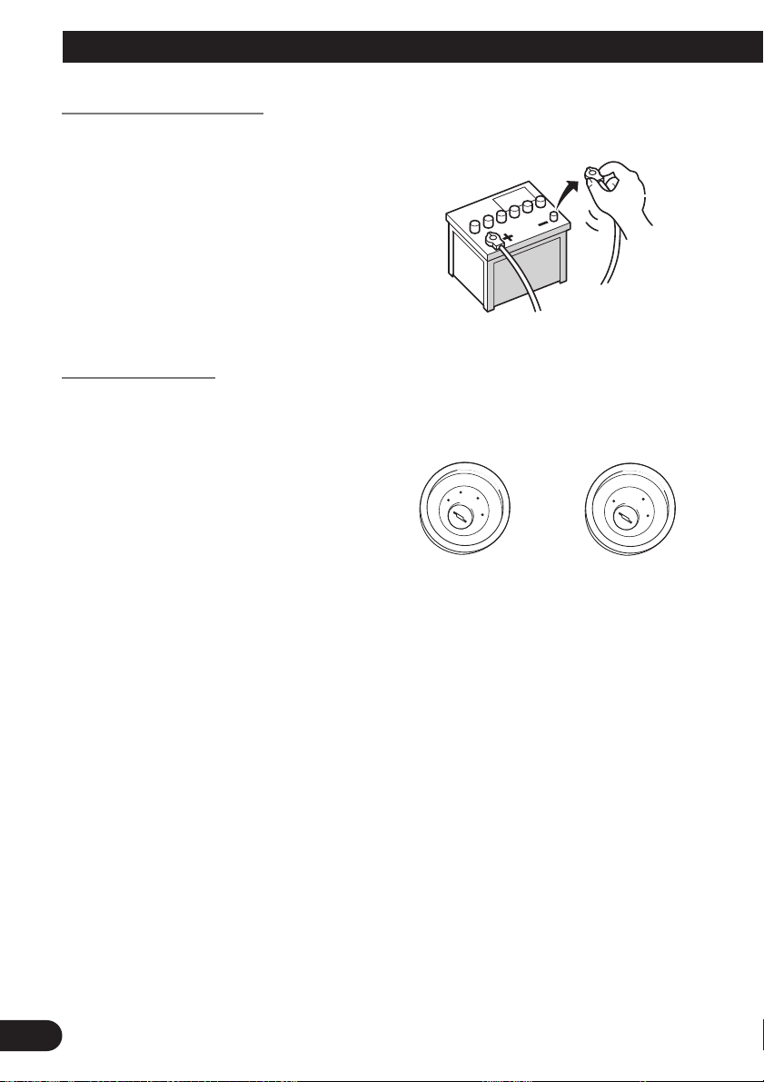
• To avoid shorts in the electrical sys-
tem, be sure to disconnect the (-) battery cable before beginning installation.
To prevent damage
• When disconnecting a connector, pull
the connector itself. Do not pull the
lead, as you may pull it out of the connector.
• If this unit is installed in a vehicle that
does not have an ACC (accessory)
position on the ignition switch, the red
lead of the unit should be connected to
a terminal coupled with ignition switch
ON/OFF operations. If this is not done,
the vehicle battery may be drained
when you are away from the vehicle
for several hours.
• To avoid short-circuiting, cover the
disconnected lead with insulating tape.
C
C
A
O
F
N
F
O
S
T
A
R
T
F
F
O
No ACC positionACC position
O
N
S
T
A
R
T
5
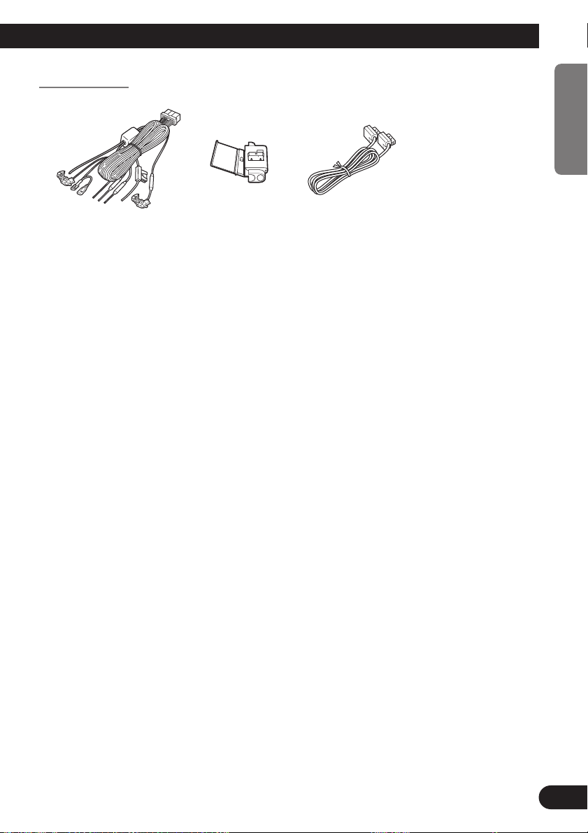
Parts supplied
ENGLISH ESPAÑOL DEUTSCH FRANÇAIS
26-pin cableConnectorPower cord
ITALIANO NEDERLANDS
6
Connecting the System
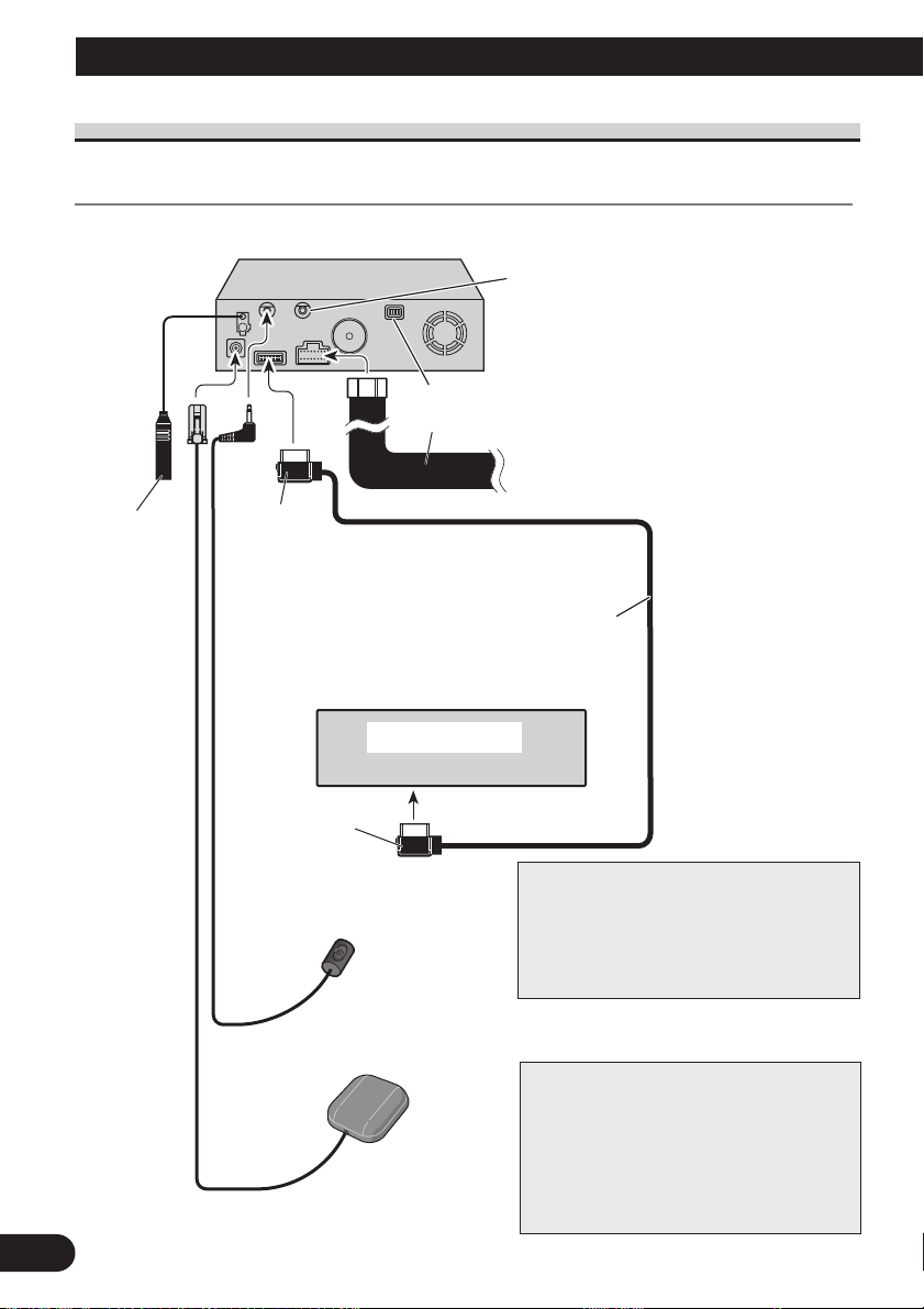
Connecting the system
Connecting to the display with 26-pin input (AVH-P7500DVD, AVH-P6500DVD, etc.)
This product
There may be no voice guidance depending on a
15 cm
Not used.
Power cord
combined display unit. In that case, an external
speaker (commercially available) must be connected to the SP-OUT jack (3.5 ø MINI JACK,
1 W max [8 Ω]) on this unit’s back.
See pages 9-11.
☞
Antenna jack
7
Black
26-pin cable (supplied)
(Ex. AVH-P7500DVD, AVH-P6500DVD
AVD-W6210, AVH-P6400CD, AVH-P6400R)
Display unit
Yellow
Microphone
See page 25.
☞
GPS aerial
See page 19.
☞
Note:
If you use equipment other than this unit
that require the connection of FM aerial,
use an adequate aerial distributor available
in the shops.
When resetting AV Head Unit
When pressing the reset button of AV Head
Unit while Navigation System and AV Head
Unit (AVH-P7500DVD, AVH-P6500DVD,
AVH-P6400CD, AVH-P6400R) are combined, make sure that ACC is tuned OFF. If
the reset button is pressed while ACC is
ON, it may not work properly.
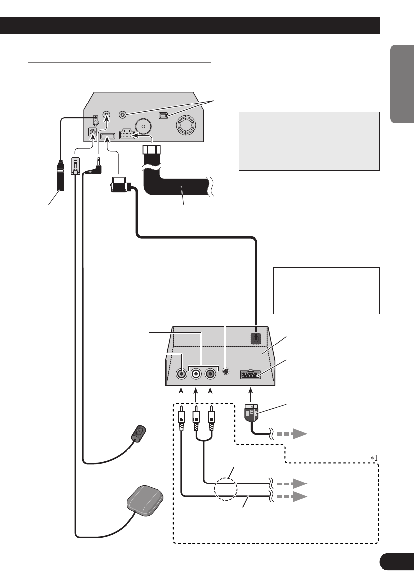
Connecting to the display with 20-pin input
This product
15 cm
Not used.
Note:
If you use equipment other than this
unit that require the connection of FM
aerial, use an adequate aerial distributor
available in the shops.
See pages 9-11.
☞
ENGLISH ESPAÑOL DEUTSCH FRANÇAIS
Antenna jack
Power cord
Level Control
This is used for adjusting output from Audio
Output. If you turn it to the right, the volume
increases, while turning it to the left reduces the
volume. (Normally, turn it fully to the right, and
instead use the external equipment outputting
sound, such as a display, for adjusting the volume.)
Audio output
Video output
Microphone
See page 25.
☞
GPS aerial
See page 19.
☞
Please make sure to complete this
connection. Otherwise you cannot
see the image of the DVD-Video.
RCA cable
(sold separately)
*1: If AVIC-800DVD is
combined, this connection is not required.
CD-RGB26P
(sold separately)
RGB output (Green)
Use this jack when
connecting the
Pioneer display.
ITALIANO NEDERLANDS
Green
To RGB input of the
display.
(Ex. AVX-7300)
To Audio inputs.
To VTR input of
the display.
8
Connecting the System
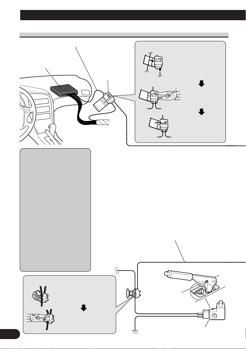
Connecting the power cord (1)
Speed detection circuit lead
Vehicle injection computer
Note: The position of the speed
detection circuit depends on the
vehicle model. For details, consult
the relevant documents from
Pioneer. When making connections for a model not listed in
those documents or for which connection to the speed detection circuit is too difficult, connect the
separately sold ND-PG1 speed
pulse generator to the pink lead.
Note: The position of the handbrake switch depends on the vehicle model. For details, consult the
vehicle owner’s manual or dealer.
Connection method
Pass the extension cord and
the lead for the speed detection circuit through this hole.
Connector
Clamp firmly with
needle-nosed pliers.
Close the cover.
Pink (CAR SPEED SIGNAL INPUT)
The mobile navigation system is connected here to detect the distance
the vehicle travels. Always connect the vehicle’s speed detection circuit or the ND-PG1 speed pulse generator, sold separately. Failure to
make this connection will increase errors in the location display.
WARNING: IMPROPER CONNECTION MAY RESULT IN
SERIOUS DAMAGE OR INJURY INCLUDING ELECRICAL
SHOCK, AND INTERFERENCE WITH THE OPERATION OF
THE VEHICLE’S ANTILOCK BRAKING SYSTEM, AUTOMATIC TRANSMISSION AND SPEEDMETER INDICATION.
Lightgreen
Used to detect the ON/OFF status of the handbrake. This lead must
be connected to the power supply side of the handbrake switch. If
this connection is made incorrectly or omitted, certain functions
of your navigation system will be unusable.
Connection method
Clamp the handbrake switch
power supply side lead.
Power supply side
Clamp firmly with
needle-nosed pliers.
9
Ground side
Handbrake switch
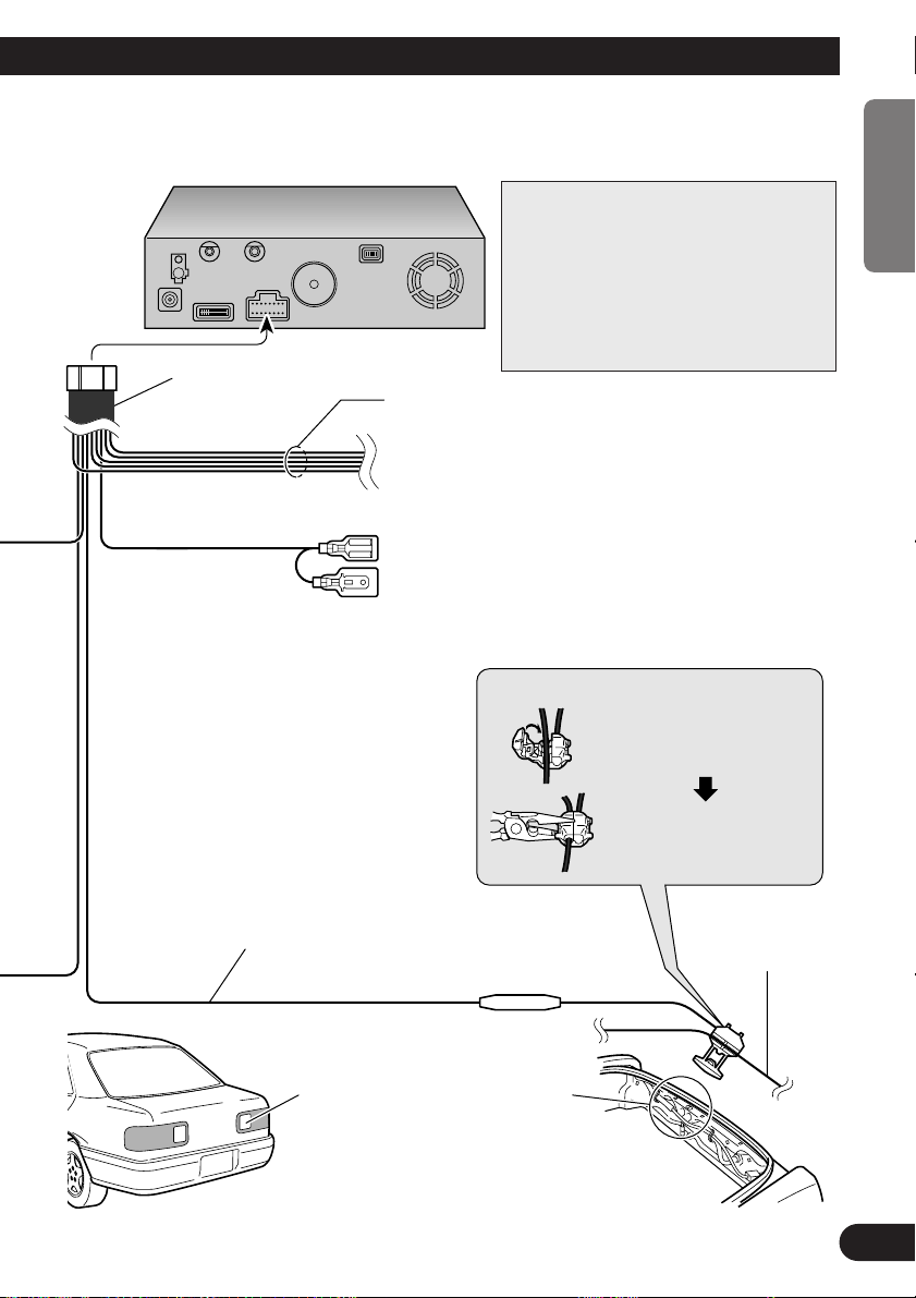
This product
Power cord
Note:
Cords for this product and those for other
products may be different colours even if
they have the same function. When connecting this product to another product,
refer to the supplied Installation manuals of
both products and connect cords that have
the same function.
Black, Orange/white, Red, Yellow
See Page 11.
☞
Yellow/black
When combining this navigation unit with a Pioneer car stereo,
if the car stereo has yellow/black leads, connect them to those
leads. In this way, when the guidance audio is output and
when you operate the system by voice, the vehicle stereo is
automatically muted to reduce the vehicle stereo volume.
ENGLISH ESPAÑOL DEUTSCH FRANÇAIS
Purple/white (REVERSEGEAR SIGNAL INPUT)
This is connected so that the navigation system can
detect whether the vehicle is moving forwards or
backwards. Connect the purple/white lead to the
lead whose voltage changes when the reverse gear
is engaged. Unless connected, the sensor may not
detect your vehicle travelling forward/backward
properly, and thus the position of your vehicle
detected by the sensor may be misaligned from the
actual position.
Note: When you use the ND-PG1 speed pulse
generator (sold separately), please make sure
to connect it.
Check the position of your vehicle’s
reversing lamp (the one that lights up
when the gearstick is in reverse [R]) and
find the reversing lamp lead in the boot.
Connection method
Clamp the reversing lamp
lead.
Clamp firmly with
needle-nosed pliers.
ITALIANO NEDERLANDS
Reversing lamp lead.
Fuse resistor
10
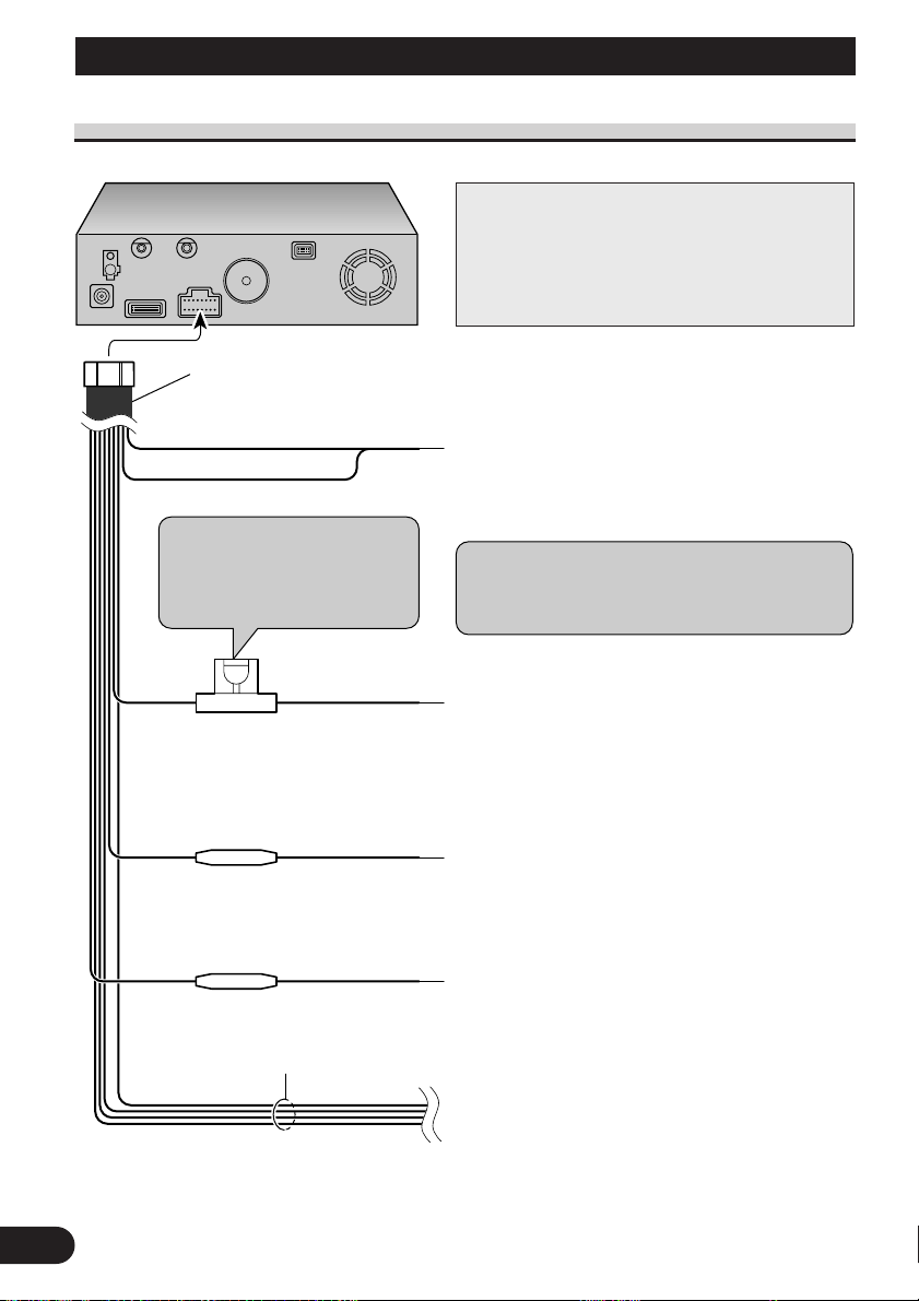
Connecting the System
This product
Yellow
To the terminal always supplied with power regardless of
ignition switch position.
Fuse holder (7.5 A)
Red
To the electric terminal controlled by the ignition switch
(12 V DC) ON/OFF.
Do not connect this lead to power source terminals to
which power is continuously supplied. If the lead is
connected to such terminals, the battery may be drained.
Orange/white
To lighting switch terminal.
Black
To vehicle (metal) body. To keep electromagnetic noise
from the vehicle body out of the mobile navigation system,
attach this lead near the main unit.
Fuse resistor
Fuse resistor
Yellow/black, Purple/white,
Pink,
Lightgreen
Note: When replacing the fuse, be
sure to use only a fuse of the rating
prescribed on the fuse holder.
Power cord
See
pages 9-11.
Note: The yellow, red, and orange/white leads should
be connected to the opposite side of the fusebox
terminals from the battery.
☞
Connecting the power cord (2)
Note:
Cords for this product and those for other products
may be different colours even if they have the same
function. When connecting this product to another
product, refer to the supplied Installation manuals
of both products and connect cords that have the
same function.
11

Installation
CAUTION
• Pioneer does not recommend that you install or service your DVD navigation
unit yourself. Installing or servicing the product may expose you to risk of
electric shock or other hazards. Refer all installation and servicing of your
navigation unit to authorised Pioneer service personnel.
• Never install the unit in places where:
* It could injure the driver or passengers if the vehicle stops suddenly.
* It may interfere with the driver’s operation of the vehicle, such as on the
floor in front of the driver’s seat.
• Make sure there is nothing behind the dashboard or panelling when drilling
holes in them. Be careful not to damage fuel lines, brake lines or power
cables.
• When using screws, do not allow them to come into contact with any electrical lead. Vibration may damage wires, leading to a short circuit or other
damage to the vehicle.
• To ensure proper installation, use the supplied parts in the manner specified.
If any parts other than the supplied ones are used, they may damage internal
parts of the unit or they may work loose and the unit may become detached.
• It is extremely dangerous to allow the GPS aerial lead or microphone lead to
become wound around the steering column or gearstick. Be sure to install
the unit in such a way that it will not obstruct driving.
ENGLISH ESPAÑOL DEUTSCH FRANÇAIS
• Make sure that leads cannot get caught in a door or the sliding mechanism of
a seat, resulting in a short circuit.
• Please confirm the proper function of your vehicle’s other equipment following installation of the DVD navigation unit.
ITALIANO NEDERLANDS
12

Installation
To guard against electromagnetic interference
• In order to prevent interference, set the following items as far as possible from the main
unit of this Navigation System, other cables or leads:
- TV aerial and aerial lead
- FM, MW/LW aerial and its lead
- GPS aerial and its lead
In addition you should lay each aerial lead as far as possible from other aerial leads.
Do not bind them together, lay them together, or cross them.
Such electromagnetic noise would increase the error for the location display.
Before installing and fixing
• Consult with your nearest dealer if installation requires the drilling of holes or other modifications of the vehicle.
• Before finally installing the unit, connect the wiring temporarily, making sure it is all
connected up properly, and the unit and the system work properly.
Before using the adhesive tape
• Make sure the surface is free of moisture, dust, grime, oil, etc. before affixing the tape.
13

Installing the main unit
5°
5°
30°
15°
Installation notes
• Do not install the main unit in places where it may become subject to high temperatures
or humidity, such as:
* Places close to a heater outlet.
* Places exposed to direct sunlight, such as on top of the dashboard or the rear shelf.
* Places that may be splashed by rain, for example close to the door.
• The installation strength will depend on the vehicle model and the installation position.
Choose a position where the main unit can be firmly installed, and install it securely.
If the main unit is not securely fastened, the errors in location display will be greater.
• Do not install the main unit on the board covering the spare tyre or other places which
are subject to vibration.
• When the main unit is installed under a front seat, ensure that it does not obstruct the
sliding action of the seat.
• Do not install the main unit where it will be under luggage. Strong mechanical shock to
the main unit would increase the errors in location display.
• Avoid installing the main unit in places where it will interfere with loading and unloading of the spare tyre, jack, tools, etc.
• Check that a disc or a PC card can be ejected with the main unit installed.
• Install the main unit on a surface within +30 degrees to -15 degrees tolerance (within
five degrees to the left or right of your vehicle’s direction of travel). A surface tilted
more than this would increase the errors in location display.
ENGLISH ESPAÑOL DEUTSCH FRANÇAIS
• Do not install the main unit vertically. Installing it this way can cause it to function
improperly.
ITALIANO NEDERLANDS
14
Installation
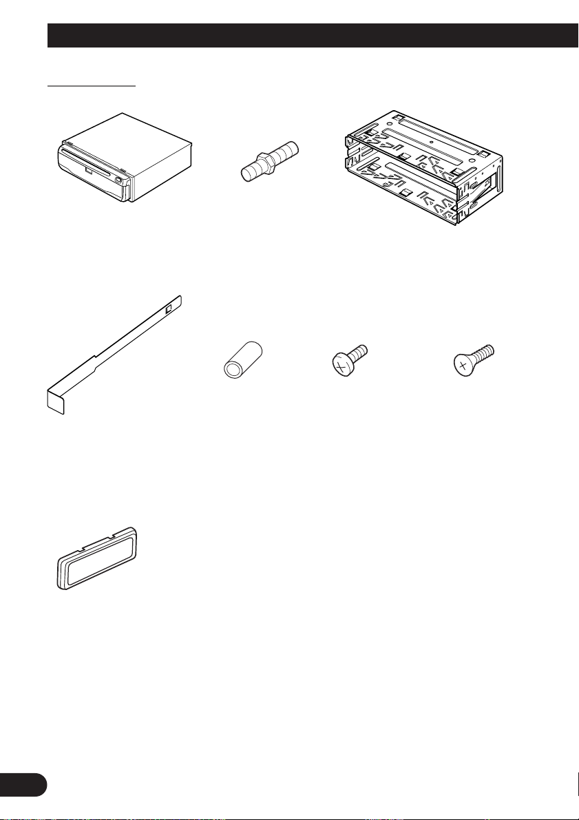
Parts supplied
Main unit
Extraction Key (2 pcs.)
Frame
Screw
Rubber bush Binding screw
(5 × 6 mm)
(4 pcs.)
Holder
Flush surface screw
(5 × 6 mm)
(4 pcs.)
15
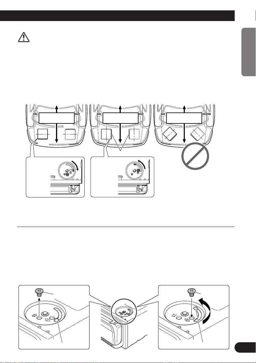
CAUTION
Locking screw
Installation direction lever
Underneath the DVD Navigation Unit
Locking screw
Installation direction lever
Front
Front Front
Front
Front
(Perpendicular)
Attachment
position of the
locking screw
↕
(Parallel)
Attachment
position of the
locking screw
↔
Forward / Backward
direction of vehicle
Forward / Backward
direction of vehicle
Forward / Backward
direction of vehicle
• Install with the left and right sides of the DVD Navigation Unit perpendicular
or parallel to your vehicle’s direction of travel. Do not install diagonally to your
vehicle’s direction of travel or the current location will be displayed incorrectly.
• If you install the left and right sides of the DVD Navigation Unit parallel to
your vehicle’s direction of travel, switch the installation direction lever, and
attach the locking screw to the “↔” side, or else the G sensor mounted in the
DVD Navigation Unit will not operate correctly.
ENGLISH ESPAÑOL DEUTSCH FRANÇAIS
If you install with the left and right sides of the DVD Navigation Unit parallel to
your vehicle’s forward / backward direction
If you install with the left and right sides of the DVD Navigation Unit parallel to your
vehicle’s forward / backward direction, remove the mounting screw underneath the DVD
Navigation Unit, and switch the installation direction lever. Then change the screw mounting position from “↔” side to “↕” side. If the screw is attached to the “↔” side, the G sensor mounted in the DVD Navigation Unit will not operate correctly.
1. Remove the locking screw attached to the installation direction lever.
2. Switch the lever, and attach the mounting screw to the “↔” side.
ITALIANO NEDERLANDS
16
Installation
After inserting the holder into the dashboard, then select the appropriate tabs
according to the thickness of the dashboard material and bend them.
(Install as firmly as possible using the
top and bottom tabs. To secure, bend
the tabs 90 degrees.)
182
53
Rubber bush
Screw
Dashboard
Holder
DIN Front/Rear-mount
This unit can be properly installed either from “Front” (conventional DIN Front-mount) or
“Rear” (DIN Rear-mount installation, utilising threaded screw holes at the sides of unit
chassis). For details, refer to the following illustrated installation methods.
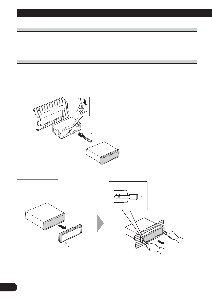
DIN Front-mount
Installation with the rubber bush
17
Removing the Unit
Pull out to remove the frame.
(When reattaching the frame, point the
side with a groove downwards and
attach it.)
Frame
Insert the supplied extraction keys into the unit, as
shown in the figure, until
they click into place.
Keeping the keys pressed
against the sides of the unit,
pull the unit out.
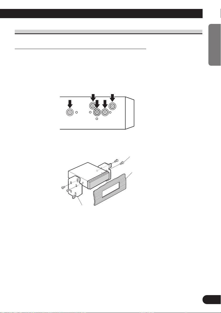
DIN Rear-mount
Installation using the screw holes on the side of the unit
• Fastening the unit to the factory radio mounting bracket.
Select a position where the screw holes of the bracket and
the screw holes of the head unit become aligned (are fitted), and tighten the screws at 2 places on each side.
Use either binding screws (5 × 6 mm) or flush surface
screws (5 × 6 mm), depending on the shape of the screw
holes in the bracket.
Screw
Dashboard or Console
ENGLISH ESPAÑOL DEUTSCH FRANÇAIS
Mounting bracket
ITALIANO NEDERLANDS
18
Installation
Dashboard
Roof
Rear shelf
Boot lid
Installing the GPS aerial
CAUTION
• Do not cut the GPS aerial lead to shorten it or use an extension to make it
longer. Altering the aerial cable could result in a short circuit.
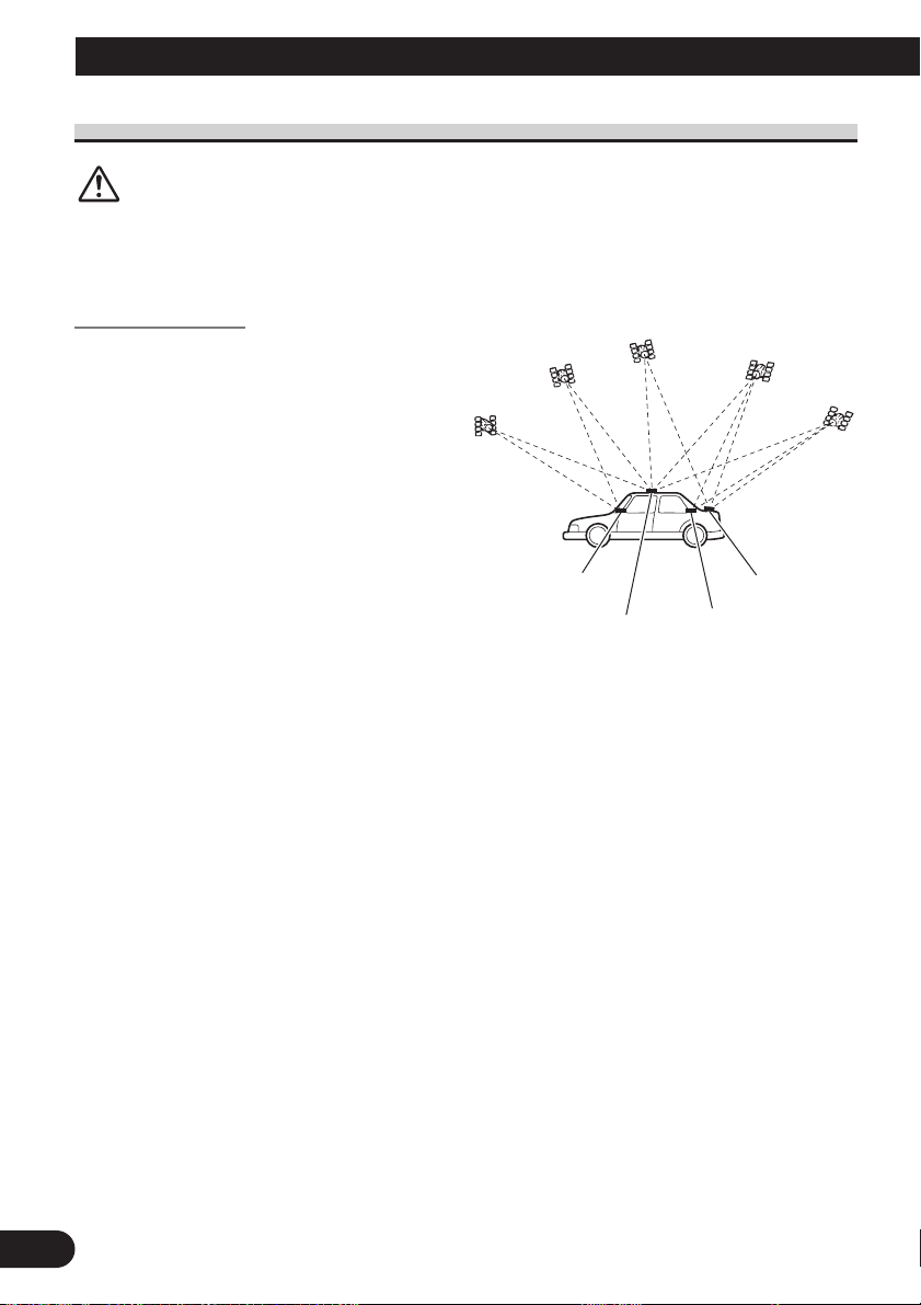
Installation notes
• The aerial should be installed on a
level surface where radio waves will
be blocked as little as possible. Radio
waves cannot be received by the aerial
if reception from the satellite is
blocked.
Installation on the vehicle roof or boot
lid is recommended to enable best
reception.
• When installing the GPS aerial inside the vehicle, be sure to use the metal sheet provided with your system. If this is not used, the reception sensitivity will be poor.
• Do not cut the accessory metal sheet. This would reduce the sensitivity of the GPS aerial.
• Take care not to pull the aerial lead when removing the GPS aerial. The magnet attached
to the aerial is very powerful, and the lead may become detached.
• The GPS aerial is installed with a magnet. When installing the GPS aerial, be careful
not to scratch the vehicle body.
• When installing the GPS aerial on the outside of the vehicle, always put it in the vehicle
when going through an automatic vehicle wash. If it is left on the outside it may be
knocked off and scratch the vehicle body.
• Do not paint the GPS aerial, as this may affect its performance.
19
Parts supplied
Metal Sheet
Peel off the protective sheet
on the rear.
Waterproof padClamp (5 pcs.)Metal sheetGPS aerial
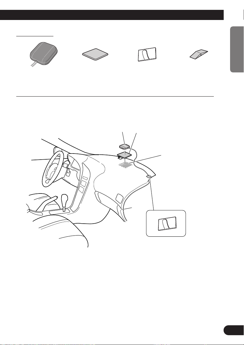
When installing the aerial inside the vehicle (on the dashboard or rear shelf)
Affix the metal sheet on as level a surface as possible where the GPS aerial faces outside
the window. Place the GPS aerial on the metal sheet. (The GPS aerial is fastened with its
magnet.)
GPS aerial
Make sure the surface is
free of moisture, dust,
grime, oil, etc., before
affixing the metal sheet.
Note: The metal sheet
contains a strong adhesive
and may leave a mark on
the dashboard if it is
removed.
ENGLISH ESPAÑOL DEUTSCH FRANÇAIS
Clamps
Use clamps to secure the
lead where necessary inside
the vehicle.
Note:
• When attaching the metal sheet, do not cut it into small pieces.
• Some models use window glass that does not allow signals from GPS satellites to pass through. On
such models, install the GPS aerial on the outside of the vehicle.
ITALIANO NEDERLANDS
20
Installation
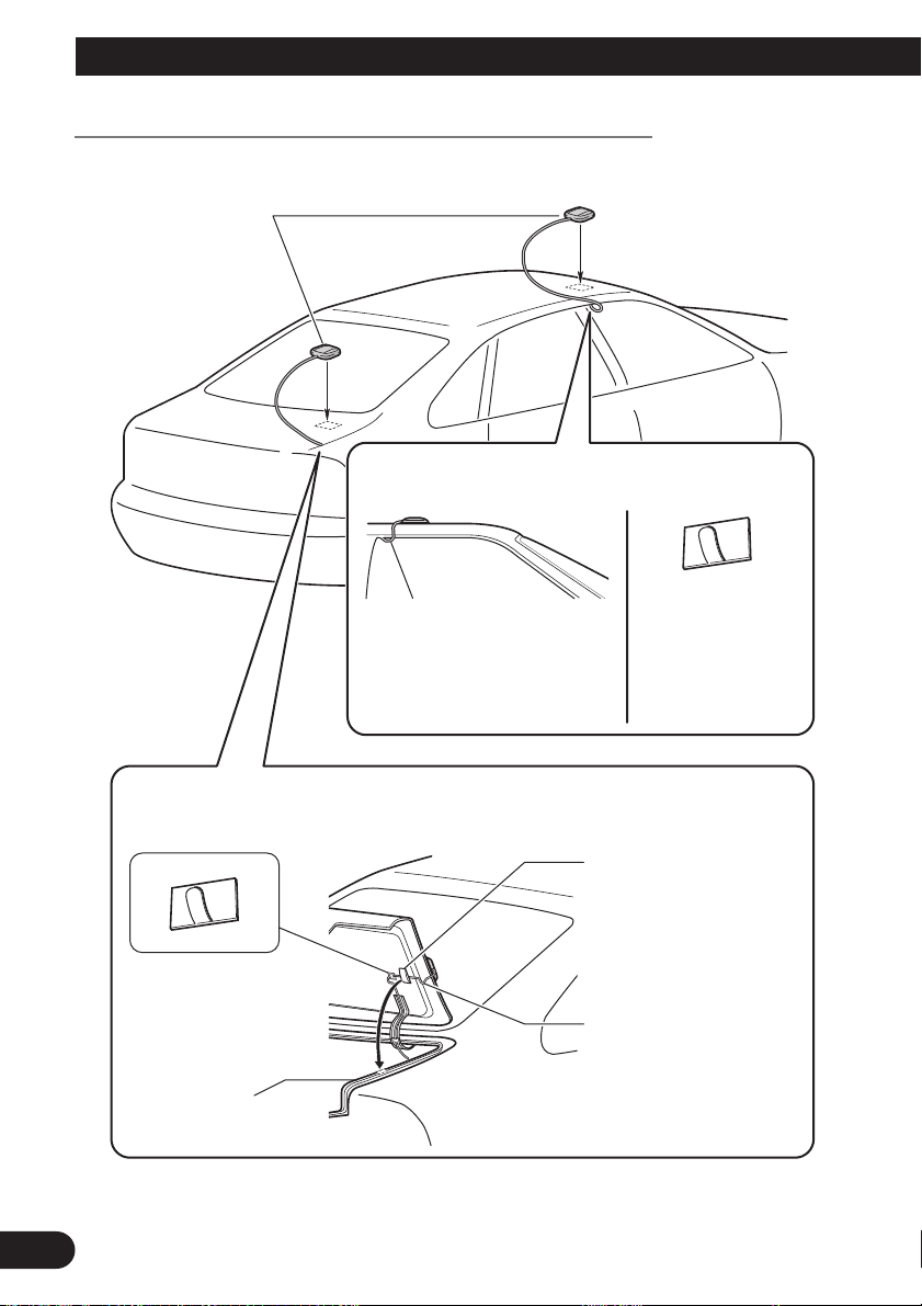
Clamps
Use clamps to secure
the lead where
necessary inside the
vehicle.
Clamps
Use clamps to secure the
lead where necessary inside
the vehicle.
GPS aerial
When routing the lead in from the top of the
door
Make a U-shaped loop in the lead
on the outside to prevent rainwater
from flowing along the lead into the
interior of the vehicle.
When routing the lead in from inside the boot
Waterproof pad
Make sure the waterproof pad
contacts the top of the rubber
packing.
Make a U-shaped loop in the
lead outside the rubber
packing to prevent rainwater
from flowing along the lead
into the interior of the vehicle.
Rubber packing
When installing the aerial outside the vehicle (on the body)
Put the GPS aerial in a position as level as possible, such as on the roof or boot lid. (The
GPS aerial is fastened with a magnet.)
21
Installing the steering remote control
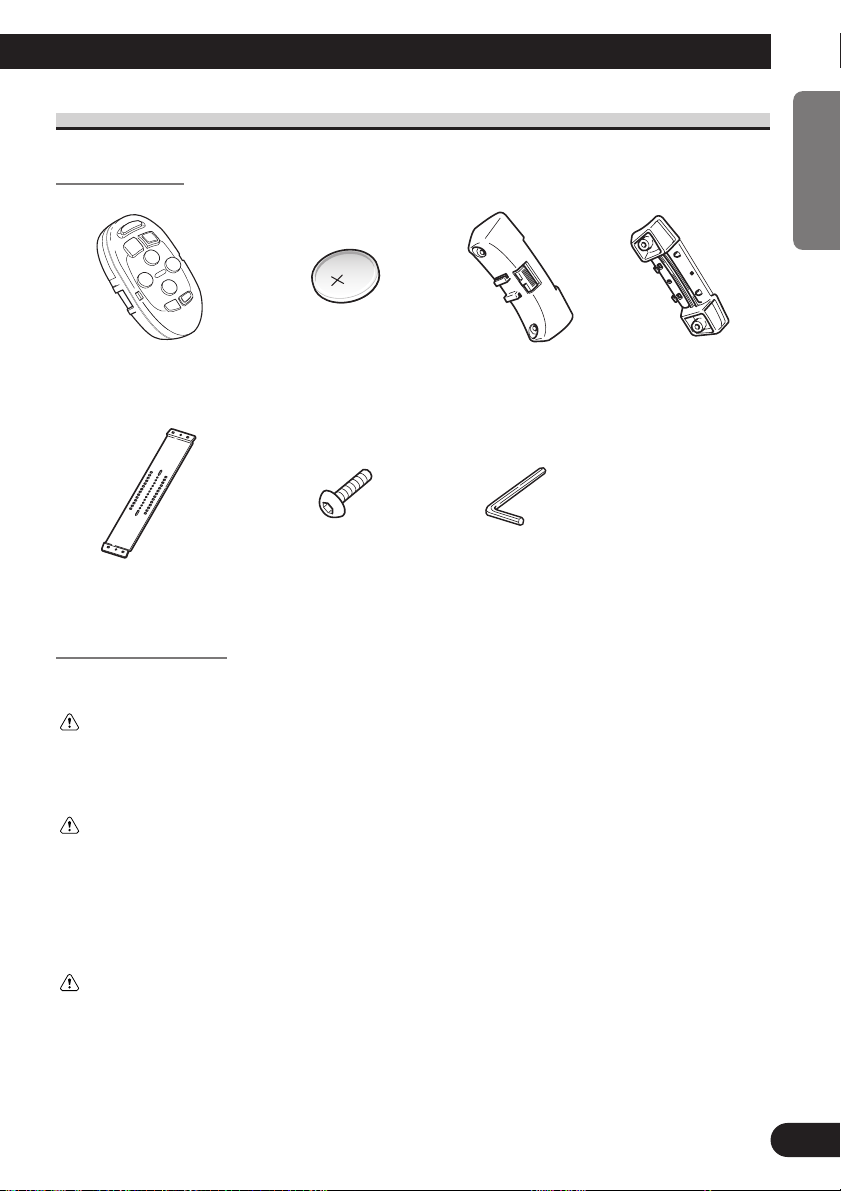
Parts supplied
ENGLISH ESPAÑOL DEUTSCH FRANÇAIS
Steering remote control
(CR2032, 3 V)
Hexagonal wrenchScrewBelt
Inner holderOuter holderLithium battery
Loading the battery
Remove the battery cover, and insert a lithium (CR2032, 3V) battery. For details, see
“Hardware Manual”.
WARNING
• Avoid installing this unit in such a location where the operation of safety devices such as airbags is prevented by this unit. Otherwise, there is a danger of a fatal accident.
• Avoid installing this unit in such a location where the operation of the steering wheel and the gearshift lever
may be prevented. Otherwise, it may result in a traffic accident.
CAUTION
• Installation of this unit requires specialized skills and experience. Installation of this unit should be entrusted
to a dealer from whom you purchased this unit.
• Install this unit using only the parts supplied with this unit. If other parts are used, this unit may be damaged
or could dismount itself, which leads to an accident or trouble.
• Install this unit as required by this manual. Failure to do so may cause an accident.
• Do not install this unit near the doors where rainwater is likely to be spilled on the unit. Incursion of water
into the unit may cause smoke or fire.
WARNING
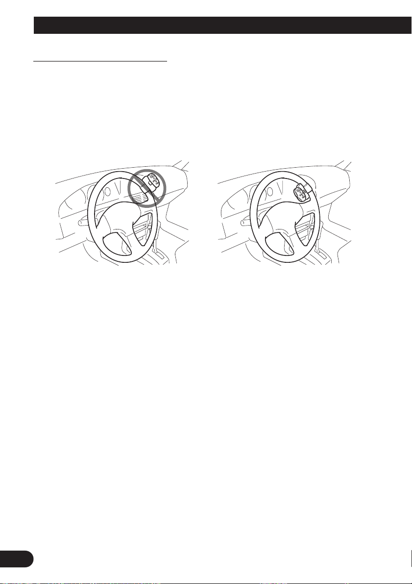
• Fix this unit securely to the steering wheel with the belt attached to the unit. If this unit is loose, it disturbs
driving stability, which may result in a traffic accident.
• Do not attach this unit to the outer circumference of the steering wheel. Otherwise, it disturbs driving stability, causing a traffic accident. Always attach this unit to the inner circumference of the steering wheel as
shown.
ITALIANO NEDERLANDS
22
Installation
Remote control handling notes
• Always keep the remote control protected from direct sunlight or high temperatures.
Leaving the remote control in places exposed to direct sunlight or high temperatures for
long periods of time may cause deformation, discolouration or malfunction.
• Replace the battery when the remote control’s performance deteriorates.
• Do not install this unit in such a place as may obstruct the driver’s view.
• Since interior layout differs depending on the type of vehicle, the ideal installation loca-
tion for the unit also differs. When installing the unit, select a location that assures optimum transmission of signals from the unit to the display.
23
Installing the holders and the steering remote control
Note:
• When the unit is installed on a right-hand-drive car, the horizontal positions are inverted.
ENGLISH ESPAÑOL DEUTSCH FRANÇAIS
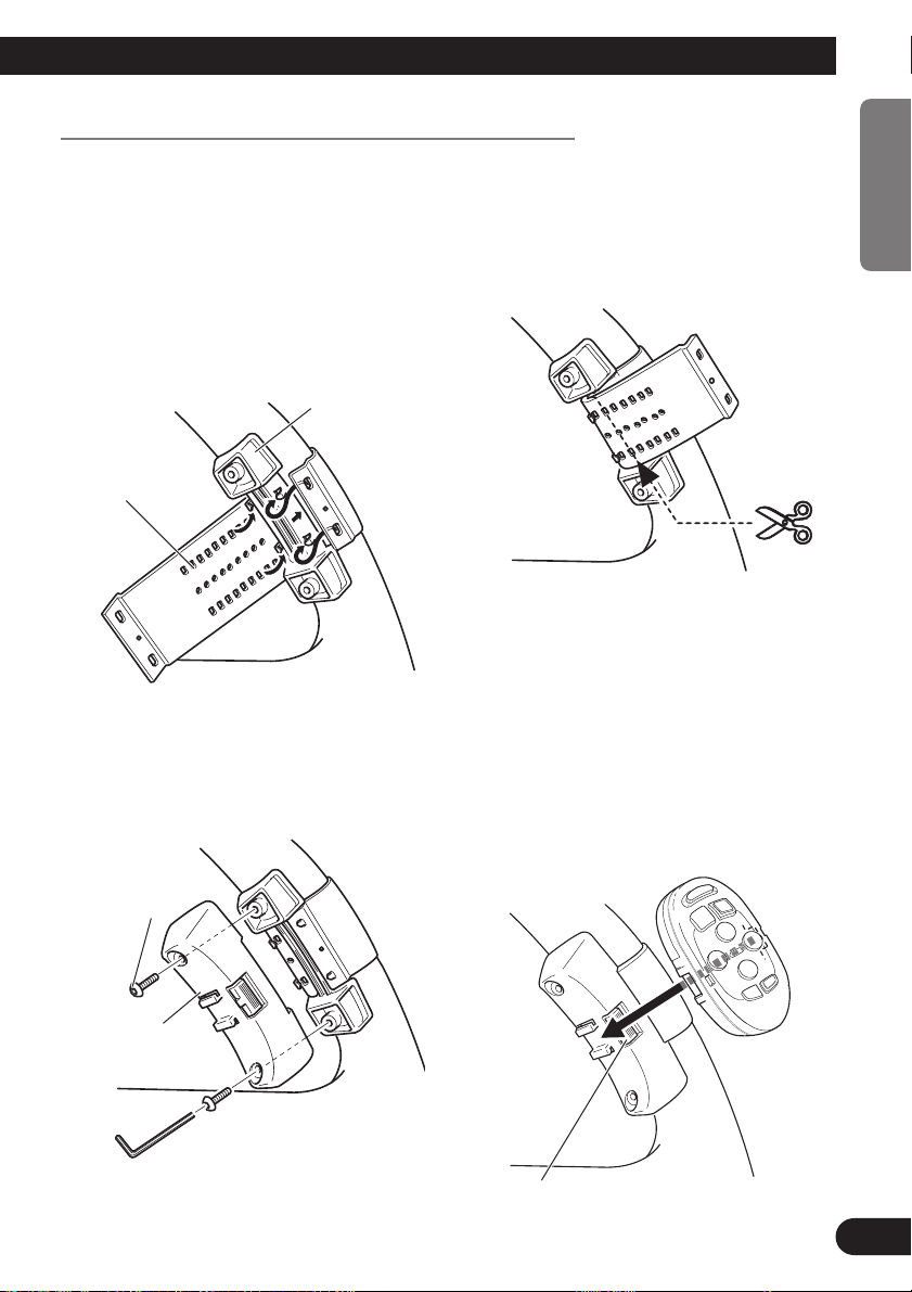
1. Secure inner holder to the inner circumference of the steering wheel
with belt.
• Fit the inner holder to the steering wheel so
that the arrow-marked side faces the driver as
shown below.
Inner holder
Belt
3. Install outer holder on the inner
holder and secure with screws.
• Tighten the screws with the supplied hexago-
nal wrench.
2. Cut the extra portion of the belt at
the center of the inner holder.
4. Install the remote control unit in
the holder.
• When removing the remote control unit from
the holder, move the corrugated release section toward the steering wheel and slide the
remote control unit toward you.
ITALIANO NEDERLANDS
Screw
Outer holder
Release Section
24
Installation
Installing the microphone
Installation notes
• Install the microphone in a position and orientation that will enable it to pick up the
voice of the person operating the system.
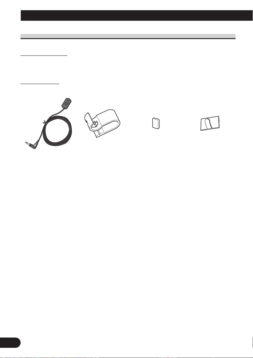
Parts supplied
Microphone clipMicrophone
Double-sided tape
(small)
Clamp
(5 pcs.)
25
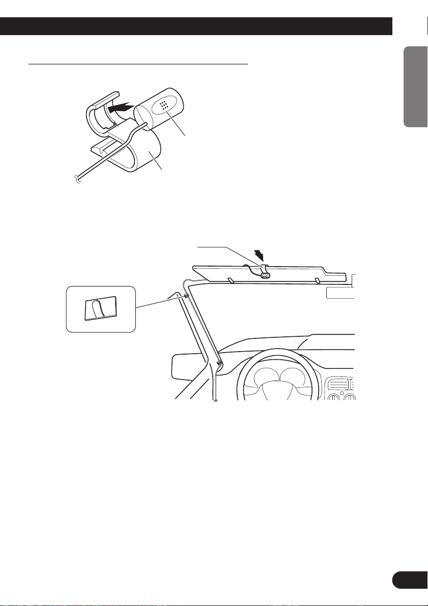
When installing the microphone on the sun visor
Microphone clip
Clamps
Use clamps to secure the
lead where necessary inside
the vehicle.
Microphone
Microphone clip
1. Install the microphone on the microphone clip.
2. Install the microphone clip on the sun visor.
With the sun visor up, install the microphone clip. (Lowering the sun visor reduces the
recognition rate for voice operations.)
ENGLISH ESPAÑOL DEUTSCH FRANÇAIS
ITALIANO NEDERLANDS
26
Installation
Clamps
Use clamps to secure the
lead where necessary inside
the vehicle.
Double-sided tape
Install the microphone clip on
the rear side of the steering
column.
Fit the microphone leadinto
the groove.
Microphone
Microphone clip
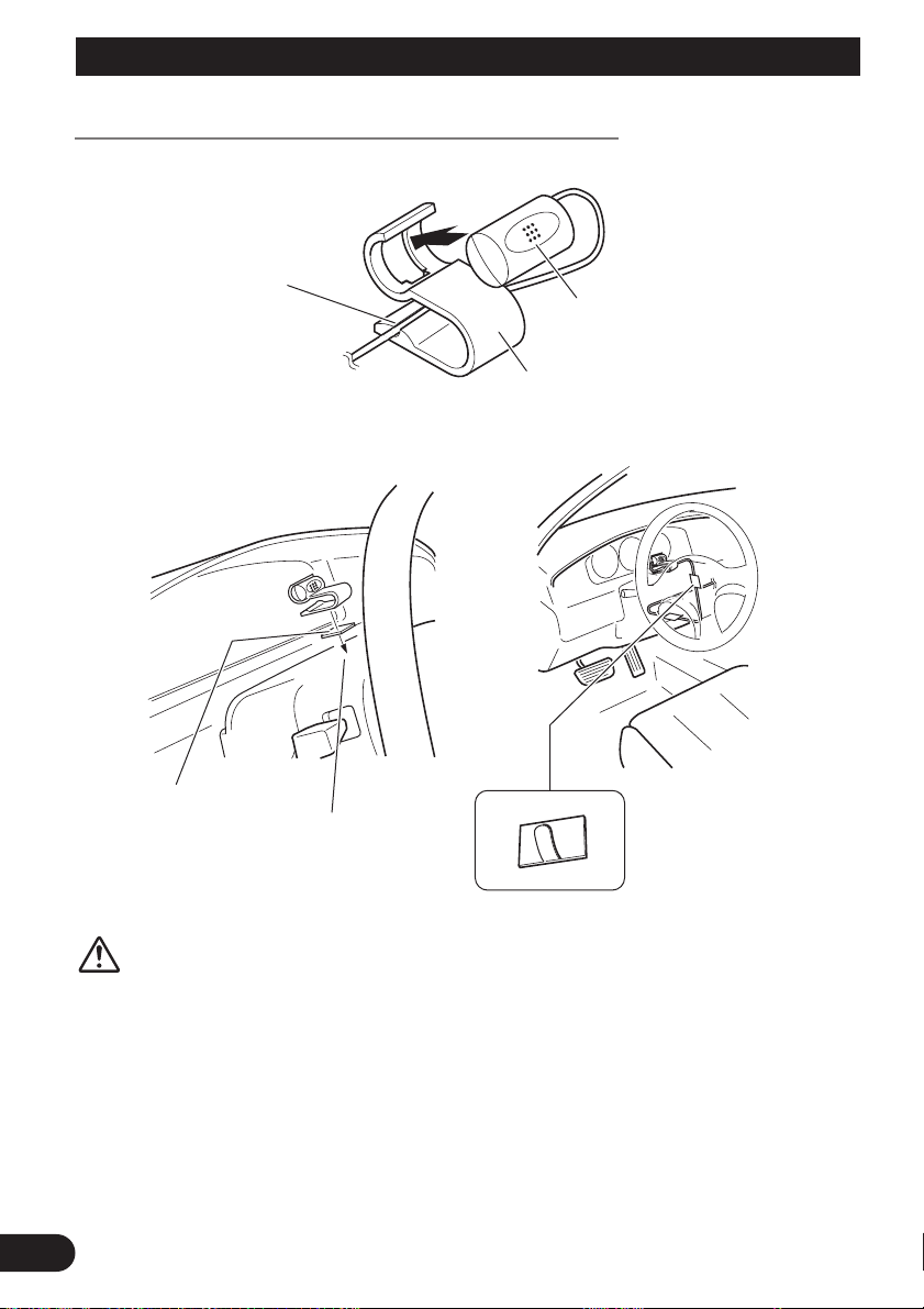
When installing the microphone on the steering column
1. Install the microphone on the microphone clip.
2. Install the microphone clip on the steering column.
CAUTION
• It is extremely dangerous to allow the microphone lead to become wound
around the steering column or gearstick. Be sure to install the unit in such a
way that it will not obstruct driving.
27
After installing the unit
1. Reconnecting the battery.
First, double-check that all connections are correct and that the unit is installed correctly.
Reassemble all vehicle components that you previously removed. Then reconnect the negative (–) cable to the negative (–) terminal of the battery.
2. Start the engine.
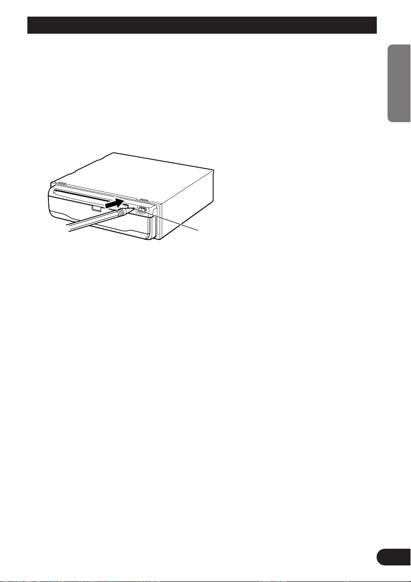
3. Press the reset button on the main unit.
Press the reset button on the main unit using a pointed object such as the point of a pen.
Reset button
4. Set the navigation system.
Set the navigation system as explained in the “Operation Manual” or “Hardware Manual”.
ENGLISH ESPAÑOL DEUTSCH FRANÇAIS
ITALIANO NEDERLANDS
28

INFORMACIÓN IMPORTANTE
ACERCA DE SU NUEVA UNIDAD DE NAVEGACIÓN CON DVD Y ESTE MANUAL
• El sistema de navegación con DVD sólo tiene la finalidad de servirle como ayuda
para manejar su vehículo. De ninguna forma debe considerarse como un acaparador de su atención, buen juicio y cuidado durante la conducción.
• No utilice su unidad de navegación con DVD para ir a lugares donde hay servicios de urgencia como hospitales o comisarias de policía. En el mapa no se indican todos los servicios de urgencia.
• No utilice la unidad de navegación con DVD si al hacerlo va a poner en peligro el
manejo seguro de su vehículo. Respete siempre las normas de conducción segura
y siga todos todas las normas de tráfico existentes.
• Este manual explica cómo instalar esta unidad de navegación con DVD en su
automóvil. El funcionamiento de este unidad de navegación con DVD se explica
en el “Manual de instruccìones” o “Manual de hardware” separado entregado
también con este sistema.
1
 Loading...