

Pioneer AVIC 8100 NEX, AVIC 7100 NEX, AVIC 6100 NEX, AVIC 5100 NEX Installation Guide

Installation Manual
Manuel d’installation
MULTIMEDIA NAVIGATION RECEIVER
RECEPTEUR DE NAVIGATION MULTIMEDIA
AVIC-8100NEX
AVIC-7100NEX
AVIC-6100NEX
AVIC-5100NEX
English Français

Contents
Precautions
Your new product and this manual 3
Important safeguards 3
Connection
Precautions before connecting the
system 5
Before installing this product 5
To prevent damage 6
– Notice for the blue/white lead 6
Parts supplied 7
Connecting the power cord (1) 8
Connecting the power cord (2) 10
Connecting the system 12
Connecting to separately sold power
amp 14
Connecting an iPhone, iPod, Android device
or a MirrorLink™ device 15
Connecting an iPhone with Lightning
connector 17
– Connecting via the USB port 17
– Connecting via the HDMI port 17
– Connecting via the RGB input 18
Connecting an iPhone with 30-pin
connector 18
– Connecting via the AUX input 18
– Connecting via the RGB input 19
Connecting the Android™ device 19
– Connecting an Android device with an
HDMI port 19
– Connecting an Android device with an
MHL port 20
Connecting the Android or MirrorLink™
device 20
Securing the High Speed HDMI
Connecting a rear view camera 22
Connecting the external video
component 23
– Using AV input 23
®
Cable 21
– Using an AUX input 24
Connecting an HDMI device 25
Connecting the rear display 25
– When using a rear display connected to
rear video output 25
Installation
Precautions before installation 26
To avoid electromagnetic interference 26
Before installing 26
– For AVIC-8100NEX and AVIC-7100NEX
users 27
Installing this product 27
– Installation notes 27
– Parts supplied 28
– Installation using the screw holes on
the side of this product 28
– Fastening the detachable faceplate 29
Installing the GPS antenna 30
– Installation notes 30
– Parts supplied 30
– When installing the antenna inside the
vehicle (on the dashboard or rear
shelf) 31
Installing the microphone 32
– Parts supplied 32
– Mounting on the sun visor 32
– Installation on the steering column 33
– Adjusting the microphone angle 33
After installation
After installing this product 34
2
En
Precautions
Your new product and this
manual
! The navigation features of this product
(and the rear view camera option if purchased) are intended solely to aid you in
the operation of your vehicle. It is not a substitute for your attentiveness, judgment
and care when driving.
! Never use this product to route to hospi-
tals, police stations, or similar facilities in
an emergency. Please call the appropriate
emergency number.
! Do not operate this product, any applica-
tions, or the rear view camera option (if purchased) if doing so will divert your attention
in any way from the safe operation of your
vehicle. Always observe safe driving rules
and follow all existing traffic regulations. If
you experience difficulty in operating this
product or reading the display, park your
vehicle in a safe location and apply the
parking brake before making the necessary
adjustments.
! This manual explains how to install this
product in your vehicle. Operation of this
product is explained in the separate manuals.
! Do not install this product where it may (i)
obstruct the driver’s vision, (ii) impair the
performance of any of the vehicle’s operating systems of safety features, including
airbags, hazard lamp buttons, or (iii) impair
the driver’s ability to safely operate the vehicle. In some cases, it may not be possible
to install this product because of the vehicle type or the shape of the vehicle interior.
! Model icons shown in this manual indicate
that the description is intended for the
models indicated by the icons.
If the following icon is shown, the description is applied only to the model shown.
e.g.)
8100NEX
Section
01
English
Important safeguards
WARNING
Pioneer does not recommend that you install
this product yourself. This product is designed for professional installation only. We
recommend that only authorized Pioneer service personnel, who have special training
and experience in mobile electronics, set up
and install this product. NEVER SERVICE
THIS PRODUCT YOURSELF. Installing or
servicing this product and its connecting
cables may expose you to the risk of electric
shock or other hazards, and can cause damage to this product that is not covered by
warranty.
! Read this manual fully and carefully before
installing this product.
! Keep this manual handy for future refer-
ence.
! Pay close attention to all warnings in this
manual and follow the instructions carefully.
! This product may in certain circumstances
display inaccurate position of your vehicle,
the distance of objects shown on the
screen, and compass directions. In addition, the system has certain limitations, including the inability to identify one-way
streets, temporary traffic restrictions and
potentially unsafe driving areas. Please exercise your own judgment in the light of actual driving conditions.
! As with any accessory in your vehicle’s in-
terior, this product should not divert your
attention from the safe operation of your
vehicle as it may result in serious injury or
death. If you experience difficulty in operating the system or reading the display,
please make adjustments while safely
parked.
! Please remember to wear your seat belt at
all times while operating your vehicle. If
you are in an accident, your injuries can be
considerably more severe if your seat belt
is not properly buckled.
En
3

Section
01
Precautions
! Certain country and government laws may
prohibit or restrict the placement and use
of this product in your vehicle. Please comply with all applicable laws and regulations
regarding the use, installation and operation of this product.
4
En
Connection
Section
02
Precautions before
connecting the system
WARNING
Do not take any steps to tamper with or disable the parking brake interlock system
which is in place for your protection. Tampering with or disabling the parking brake interlock system could result in serious injury or
death.
CAUTION
! If you decide to perform the installation
yourself, and have special training and experience in the mobile electronics installations, please carefully follow all of the
steps in the installation manual.
! Secure all wiring with cable clamps or
electrical tape. Do not allow any bare wiring to remain exposed.
! Do not directly connect the yellow lead of
this product to the vehicle battery. If the
lead is directly connected to the battery,
engine vibration may eventually cause
the insulation to fail at the point where
the wire passes from the passenger compartment into the engine compartment. If
the yellow lead’s insulation tears as a result of contact with metal parts, short-circuiting can occur, resulting in
considerable danger.
! It is extremely dangerous to allow cables
to become wound around the steering column or shift lever. Be sure to install this
product, its cables, and wiring away in
such so that they will not obstruct or hinder driving.
! Make sure that the cables and wires will
not interfere with or become caught in
any of the vehicle’s moving parts, especially the steering wheel, shift lever, parking brake, sliding seat tracks, doors, or
any of the vehicle’s controls.
! Do not route wires where they will be ex-
posed to high temperatures. If the insulation heats up, wires may become
damaged, resulting in a short circuit or
English
malfunction and permanent damage to
the product.
! Do not cut the GPS antenna cable to
shorten it or use an extension to make it
longer. Altering the antenna cable could
result in a short circuit or malfunction.
! Do not shorten any leads. If you do, the
protection circuit (fuse holder, fuse resistor or filter, etc.) may fail to work properly.
! Never feed power to other electronic pro-
ducts by cutting the insulation of the
power supply lead of this product and tapping into the lead. The current capacity of
the lead will be exceeded, causing overheating.
Before installing this product
! Use this unit with a 12-volt battery and ne-
gative grounding only. Failure to do so may
result in a fire or malfunction.
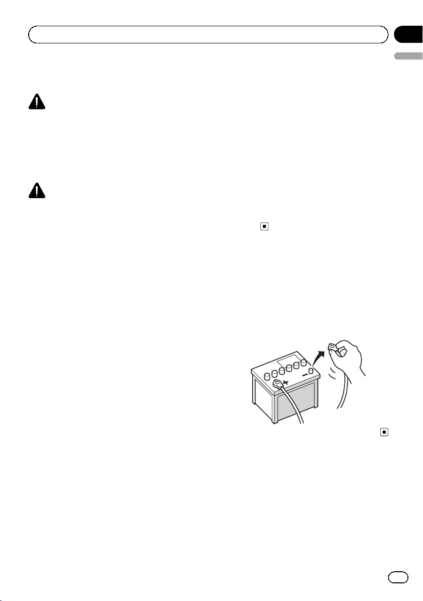
! To avoid shorts in the electrical system, be
sure to disconnect the (–) battery cable before installation.
En
5
y
Section
02
Connection
To prevent damage
WARNING
! Use speakers over 50 W (output value)
and between 4 W to 8 W (impedance value).
Do not use 1 W to 3W speakers for this
unit.
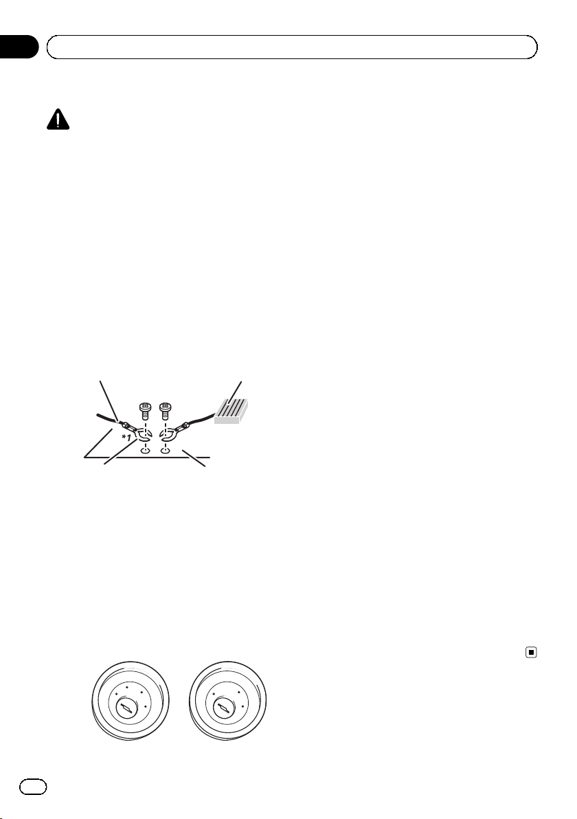
! The black cable is ground. When instal-
ling this unit or power amp (sold separately), make sure to connect the ground
wire first. Ensure that the ground wire is
properly connected to metal parts of the
car’s body. The ground wire of the power
amp and the one of this unit or any other
device must be connected to the car separately with different screws. If the screw
for the ground wire loosens or falls out, it
could result in fire generation of smoke or
malfunction.
Ground wire
Other devices
(Another electronic
device in the car)
*1
Not supplied for this unit.
Metal parts of car’s bod
! When replacing the fuse, be sure to only
use a fuse of the rating prescribed on this
product.
! When disconnecting a connector, pull the
connector itself. Do not pull the lead, as
you may pull it out of the connector.
! This product cannot be installed in a vehi-
cle without ACC (accessory) position on
the ignition switch.
C
C
A
O
F
N
F
O
S
T
A
R
T
Power amp
F
F
O
O
N
S
T
A
R
T
! To avoid short-circuiting, cover the discon-
nected lead with insulating tape. It is especially important to insulate all unused
speaker leads, which if left uncovered may
cause a short circuit.
! Attach the connectors of the same color to
the corresponding colored port, i.e., blue
connector to the blue port, black to black,
etc.
! Refer to the owner’s manual for details on
connecting the power amp and other units,
then make connections accordingly.
! Since a unique BPTL circuit is employed,
do not directly ground the * side of the
speaker lead or connect the * side of another side of the speaker lead together. Be
sure to connect the * side of the speaker
lead to the * side of the speaker lead on
this product.
Notice for the blue/white lead
! When the ignition switch is turned on (ACC
ON), a control signal is output through the
blue/white lead. Connect to an external
power amp’s system remote control terminal, the auto-antenna relay control terminal, or the antenna booster power control
terminal (max. 300 mA 12 VDC). The control signal is output through the blue/white
lead, even if the audio source is switched
off.
! Be sure not to use this lead as the power
supply lead for the external power amps.
Such connection could cause excessive
current drain and malfunction.
! Be sure not to use this lead as the power
supply lead for the auto-antenna or antenna booster. Such connection could cause
excessive current drain and malfunction.
ACC position No ACC position
6
En
Connection
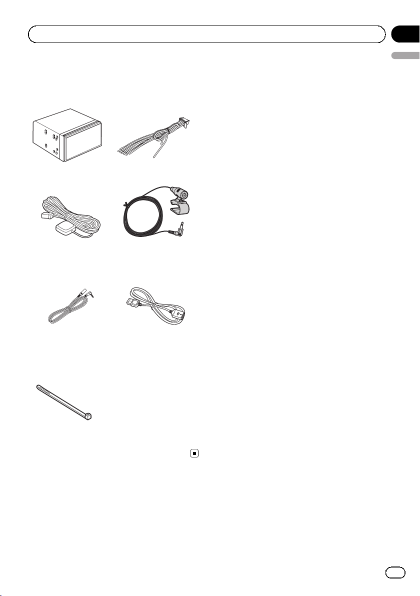
Parts supplied
Parts marked (*) are supplied with AVIC8100NEX, AVIC-7100NEX and AVIC-6100NEX.
This product Power cord
GPS antenna Microphone
Section
02
English
Mini-jack extension
cable
Lock tie*
USB cable
En
7
Section
02
Connection
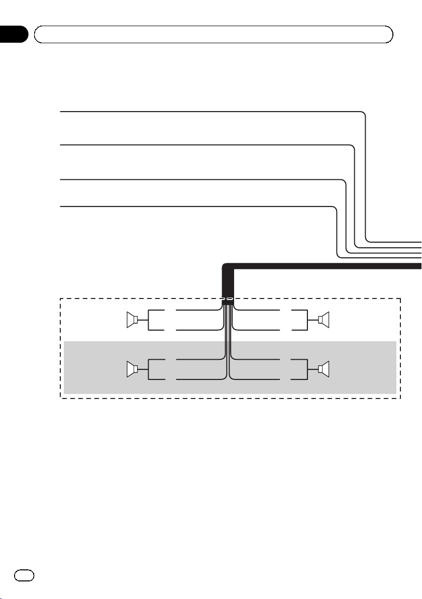
Connecting the power cord (1)
Yellow
To terminal supplied with power regardless of
ignition switch position.
Red
To electric terminal controlled by ignition
switch (12 V DC) ON/OFF.
Orange/white
To lighting switch terminal.
Black (ground)
To vehicle (metal) body.
Left Right
Rear speaker Rear speaker
With a two-speaker system, do not connect anything
to the speaker leads that are not connected to
speakers.
White
White/black Gray/black
Green
Green/black
Gray
Violet
Violet/black
Front speakerFront speaker
8
En
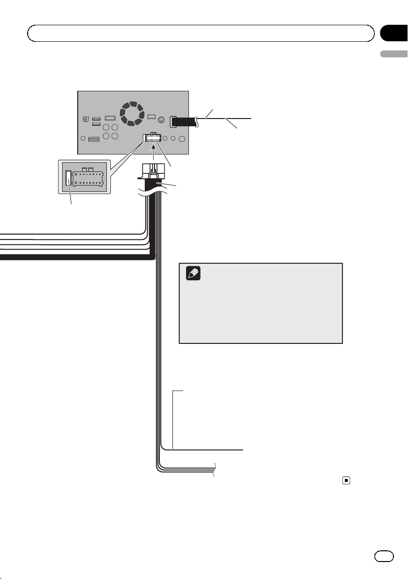
Connection
This product
Fuse (10 A)
14 cm (5-1/2 in.)
Yellow/black (MUTE)
If you use equipment with a mute
function, connect that equipment to
Power supply
Power cord
the Audio Mute lead. If not, keep the
Audio Mute lead free of any
connections.
Note
Audio source will be set to mute or attenuate, while
the following sounds will not be muted or
attenuated. For details, refer to Operation Manual.
—
Voice guidance of the navigation
—
Incoming ring tone and incoming voice of the
cellular phone that is connected to this product
via Bluetooth wireless technology
Section
02
English
Blue/white (SYSTEM REMOTE CONTROL)
To auto-antenna relay control terminal or antenna
booster power control terminal (max. 300 mA 12 V DC).
If the vehicle has a glass antenna, connect to the
antenna booster power control terminal (max. 300 mA
12 V DC).
En
9
Section
02
Connection
Connecting the power cord (2)
Pink (CAR SPEED SIGNAL INPUT)
This product is connected here to detect the distance the vehicle travels. Always connect the
vehicle’s speed detection circuit. Failure to make this connection will increase errors in the
vehicle’s location display.
WARNING
IMPROPER CONNECTION MAY RESULT IN SERIOUS DAMAGE OR INJURY INCLUDING
ELECTRICAL SHOCK, AND INTERFERENCE WITH THE OPERATION OF THE VEHICLE´S
ANTILOCK BRAKING SYSTEM, AUTOMATIC TRANSMISSION AND SPEEDOMETER
INDICATION.
CAUTION
It is strongly suggested that the speed pulse wire be connected for accuracy of navigation
and better performance.
Note
The position of the speed detection circuit and the position of the parking brake switch
vary depending on the vehicle model. For details, consult your authorized Pioneer dealer
or an installation professional.
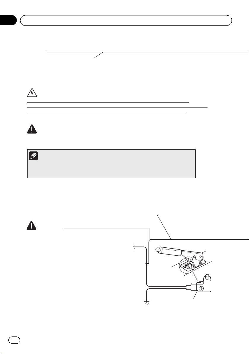
Light green (PARKING BRAKE)
Used to detect the ON/OFF status of the parking brake. This lead must be connected to the power supply
side of the parking brake switch.
If this connection is made incorrectly or omitted, certain functions of this product will be
unusable.
WARNING
LIGHT GREEN LEAD AT POWER CONNECTOR IS
DESIGNED TO DETECT PARKED STATUS AND
MUST BE CONNECTED TO THE POWER SUPPLY
SIDE OF THE PARKING BRAKE SWITCH.
IMPROPER CONNECTION OR USE OF THIS
LEAD MAY VIOLATE APPLICABLE LAW AND MAY
RESULT IN SERIOUS INJURY OR DAMAGE.
Power supply side
Ground side
Parking brake switch
10
En
Connection
Section
02
English
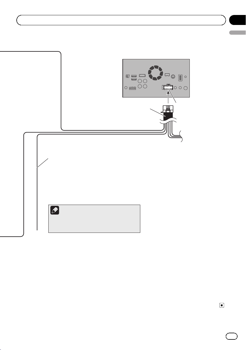
This product
Power cord
Violet/white (REVERSE-GEAR SIGNAL INPUT)
This is connected so that this product can detect whether
the vehicle is moving forwards or backwards. Connect the
violet/white lead to the lead whose voltage changes when
the shift lever is put in reverse. Unless connected, the
sensor may not detect your vehicle traveling
forward/backward properly, and thus the position of your
vehicle detected by the sensor may be misaligned from the
actual position.
Note
When you use a rear view camera, please make
sure to connect this lead. Otherwise you cannot
switch to the rear view camera picture.
Power supply
En
11
Section
02
Connection
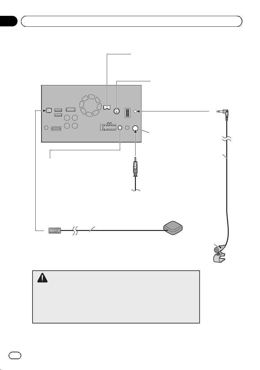
Connecting the system
iDatalink adapter input
Please refer to the instruction
manual for the iDatalink adapter
(sold separately).*
This product
Wired remote input
Please refer to the instruction manual for
the Hard-wired remote control adapter
(sold separately).
3.55 m (11 ft. 8 in.)
Vehicle antenna
SiriusXM Connect Vehicle Tuner
Please refer to the instruction manual
for SiriusXM Connect Vehicle Tuner
(sold separately).
Antenna jack
4 m (13 ft. 1 in.)
GPS antenna
Microphone
12
WARNING
· To avoid the risk of accident and the potential violation of applicable laws, this
product should never be used while the vehicle is being driven except for
navigation purposes. And, also rear displays should not be in a location where it
is a visible distraction to the driver.
· In some countries, the viewing of images on a display inside a vehicle even by
persons other than the driver may be illegal. Where such regulations apply they
must be obeyed and this product’s video source should not be used.
En
Connection
Notes
!*Before using and/or connecting the iData-
link Maestro adapter, you will need to first
flash the Maestro module with the appropriate
vehicle and head unit firmware. You can find
the device number that is required for the activation on the followings (refer to Operation
Manual.):
— the label on the packaging of this product
— the label on this product
— the “Firmware Information” screen
8100NEX 7100NEX
! Make sure to connect the microphone sup-
plied with this product when using Android
Auto.
Section
02
English
En
13
Section
02
Connection
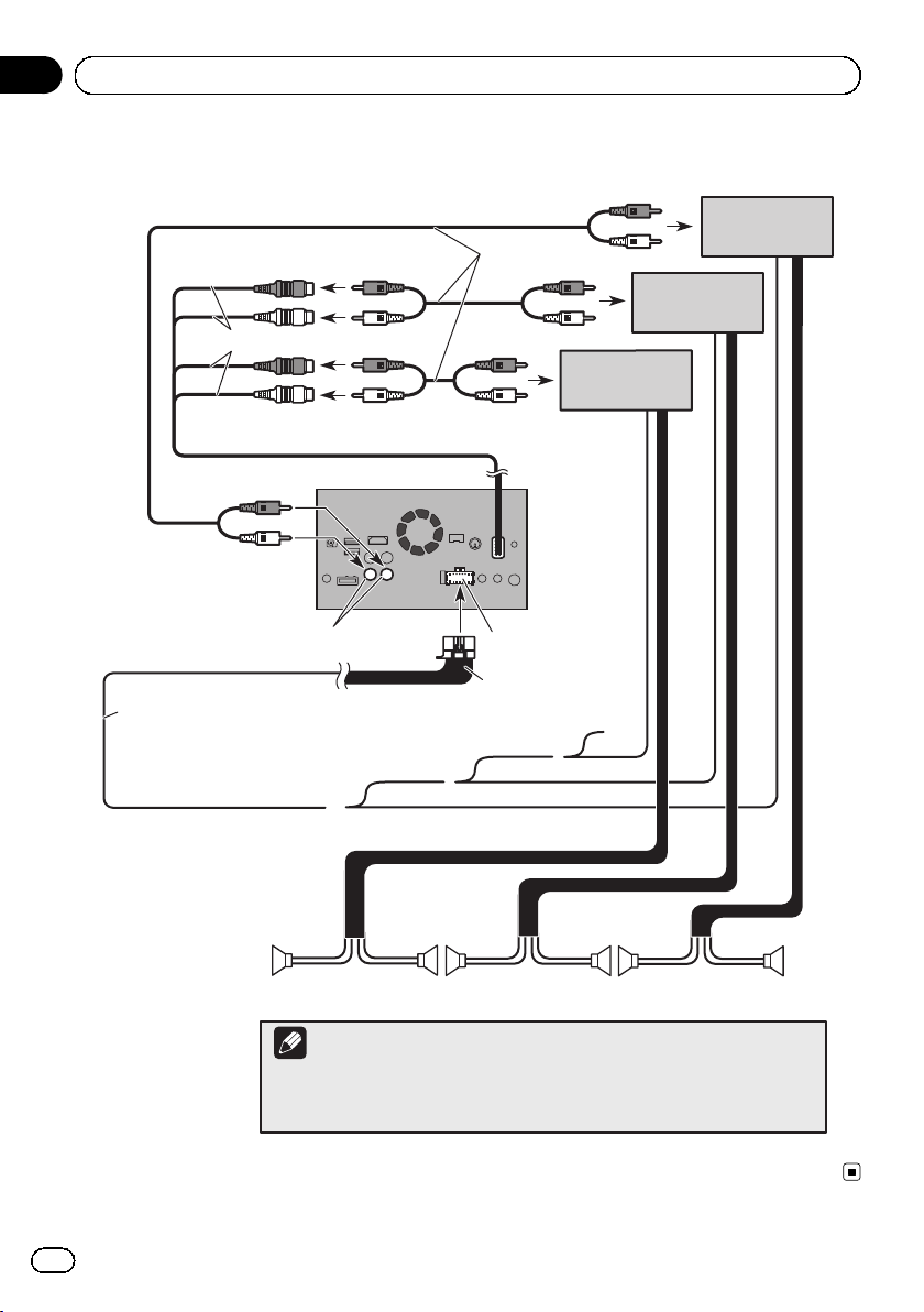
Connecting to separately sold power amp
RCA
Rear outputs
(REAR OUTPUT)
15 cm (5-7/8 in.)
Front outputs
(FRONT OUTPUT)
This product
cables
(sold separately)
Power amp
(sold separately)
Power amp
(sold separately)
Power amp
(sold separately)
14
White, Red (SWL, SWR)
Blue/white
To system control terminal of the power amp
(max. 300 mA 12 V DC).
Front speaker
Notes
· You can change the RCA output of the subwoofer depending on your subwoofer
system. (Refer to Operation Manual.)
· The subwoofer output of this product is monaural.
En
Power supply
Power cord
System remote control
Rear speaker
Subwoofer
Connection
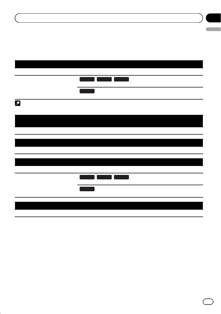
Connecting an iPhone, iPod, Android device or a
™
MirrorLink
Find your device and the function you want to operate from the list below, and refer to the page for the connection.
iPhone 6 Plus/iPhone 6/iPhone 5s/iPhone 5c/iPhone 5
iPod (audio) Refer to Connecting via the USB port on page 17.
AppRadio Mode
Note
For any of the connections mentioned above, aha, AVICSYNC App and Pandora are available for use.
iPhone 3GS/iPod touch (2nd and 3rd generation)/iPod classic 160GB/iPod classic 80GB/iPod nano (3rd,
4th, 5th, and 6th generation)
Refer to Connecting via the AUX input on page 18.
iPhone 4s/iPhone 4/iPod touch (4th generation)
Refer to Connecting via the RGB input on page 19.
iPod touch (5th generation)
iPod (audio) Refer to Connecting via the USB port on page 17.
AppRadio Mode
device
8100NEX 7100NEX 6100NEX
Refer to Connecting via the HDMI port on page 17.
5100NEX
Refer to Connecting via the RGB input on page 18.
8100NEX 7100NEX 6100NEX
Refer to Connecting via the HDMI port on page 17.
5100NEX
Refer to Connecting via the RGB input on page 18.
Section
02
English
iPod nano (7th generation)
Refer to Connecting via the USB port on page 17.
En
15
Section
02
Connection
Android device
HDMI port
8100NEX 7100NEX 6100NEX
AppRadio Mode
8100NEX 7100NEX
Android Auto
Note
For any of the connections mentioned above, aha, AVICSYNC App and Pandora are available for use.
MirrorLink device
Refer to Connecting the Android or MirrorLink
Refer to Connecting an Android device with an HDMI port on page 19.
MHL port
Refer to Connecting an Android device with an MHL port on page 20.
Refer to Connecting the Android or MirrorLink
™
device on page 20.
™
device on page 20.
16
En
Connection
Connecting an iPhone with
Lightning connector
Notes
! For details on how to connect an external de-
vice using a separately sold cable, refer to the
manual for the cable.
! For details concerning the connection, opera-
tions and compatibility of iPhone, refer to Operation Manual.
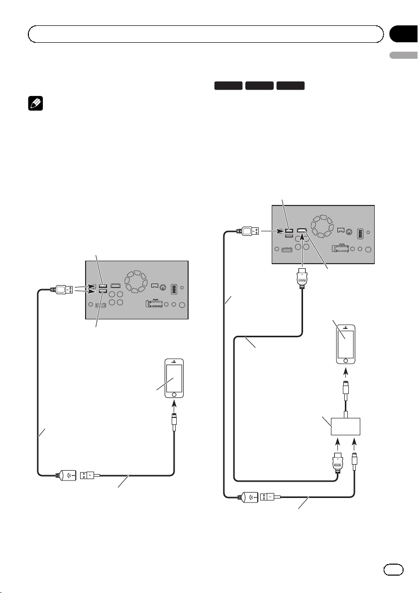
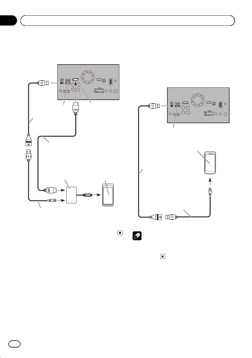
Connecting via the HDMI port
8100NEX 7100NEX
The following cables are required for the connection.
! HDMI interface cable for iPod / iPhone
(CD-IH202) (sold separately)
! USB interface cable for iPod / iPhone (CD-
IU52) (sold separately)
! Lightning Digital AV Adapter (Apple Inc.
products) (sold separately)
6100NEX
Section
02
English
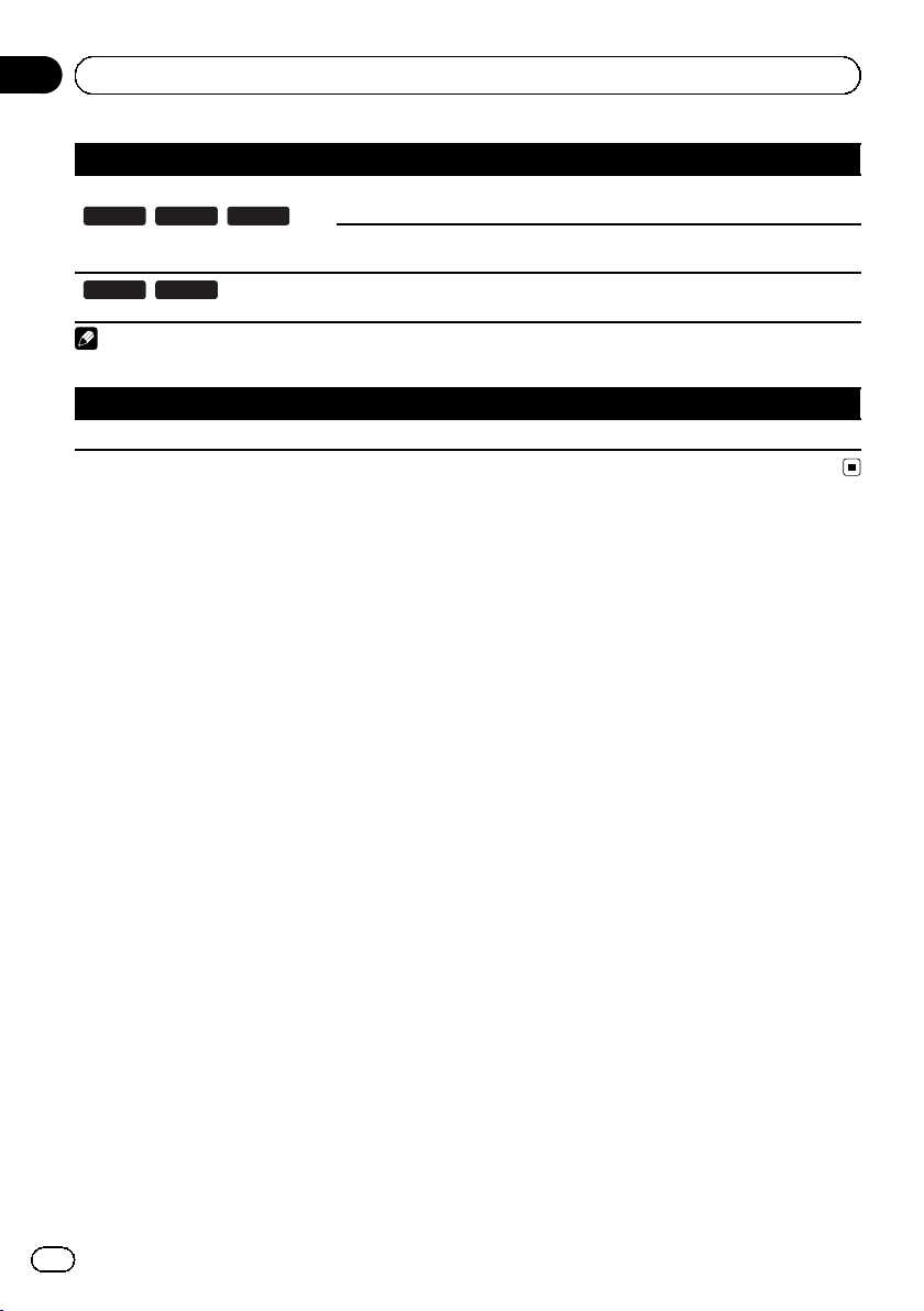
Connecting via the USB port
The USB interface cable for iPod / iPhone (CDIU52) (sold separately) is required for the connection.
USB port 1
USB port 2
iPhone with
Lightning connector
USB cable
1.5 m (4 ft. 11 in.)
This product
USB port 1
USB cable
1.5 m (4 ft. 11 in.)
®
High Speed HDMI
(Type A - A)
(supplied with CD-IH202)
Lightning Digital AV Adapter
(Apple Inc. products)
(sold separately)
Cable
This product
HDMI port
iPhone with
Lightning connector
USB interface cable for iPod / iPhone
(CD-IU52) (sold separately)
USB interface cable for iPod / iPhone
(CD-IU52) (sold separately)
En
17
Section
02
Connection
Note
! When you connect the High Speed HDMI
®
Cable, use the lock tie to fix it securely.
= For details, refer to Securing the High
Speed HDMI
®
Cable on page 21.
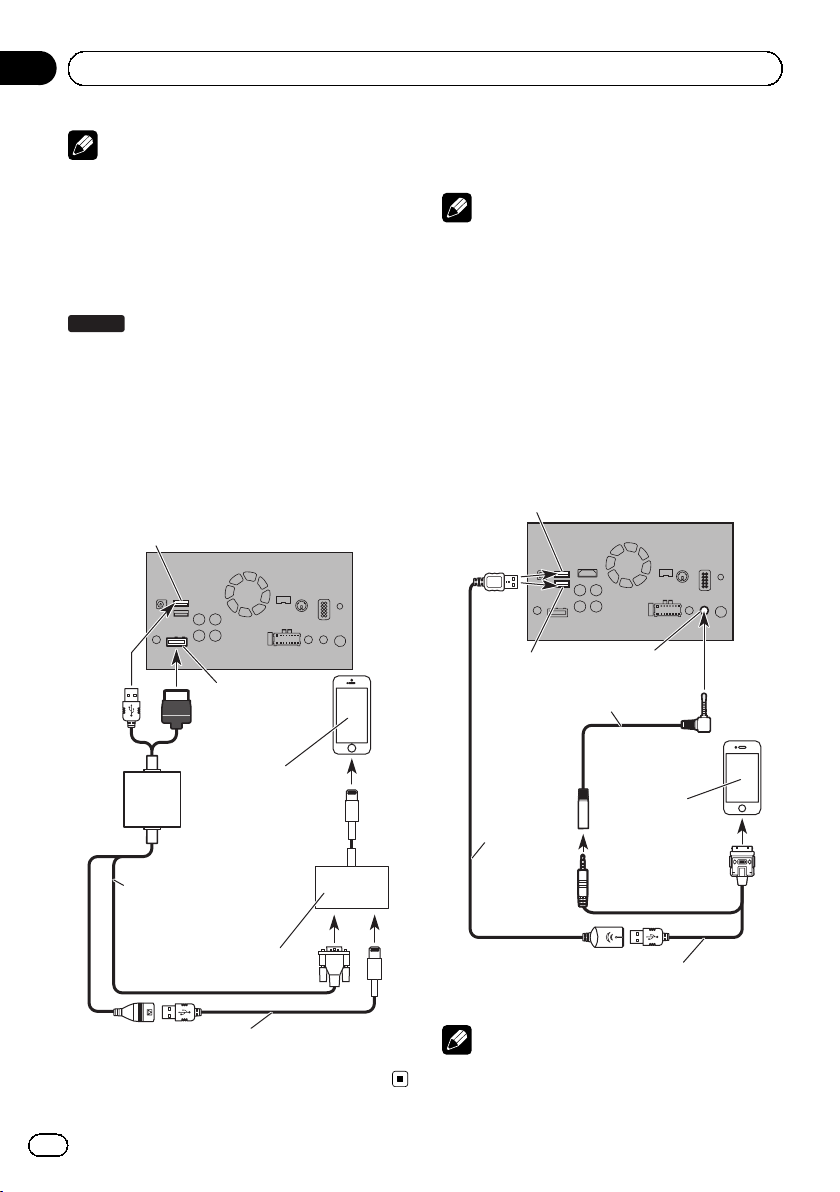
Connecting via the RGB input
5100NEX
The following cables are required for the connection.
! VGA/USB interface cable for iPod / iPhone
(CD-IV202AV) (sold separately)
! USB interface cable for iPod / iPhone (CD-
IU52) (sold separately)
! Lightning to VGA Adapter (Apple Inc. pro-
ducts) (sold separately)
USB port 1
This product
RGB input
Connecting an iPhone with
30-pin connector
Notes
! For details on how to connect an external de-
vice using a separately sold cable, refer to the
manual for the cable.
! For details concerning the connection, opera-
tions and compatibility of iPhone, refer to Operation Manual.
Connecting via the AUX input
The USB interface cable for iPod / iPhone (CDIU201V) (sold separately) is required for the
connection.
USB port 1
USB port 2
Mini-jack extension cable
2 m (6 ft. 7 in.)
This product
AUX input
18
VGA/USB interface cable
for iPod / iPhone
(CD-IV202AV) (sold separately)
Lightning to VGA Adapter
(Apple Inc. products)
(sold separately)
USB interface cable for iPod / iPhone
(CD-IU52) (sold separately)
En
iPhone with
Lightning connector
iPhone with
30-pin connector
USB cable
1.5 m
(4 ft. 11 in.)
USB interface cable for iPod / iPhone
(CD-IU201V) (sold separately)
Note
Connect the USB cable to USB port 1 when using
“aha” or “Pandora” as the source.
Connection
Section
02
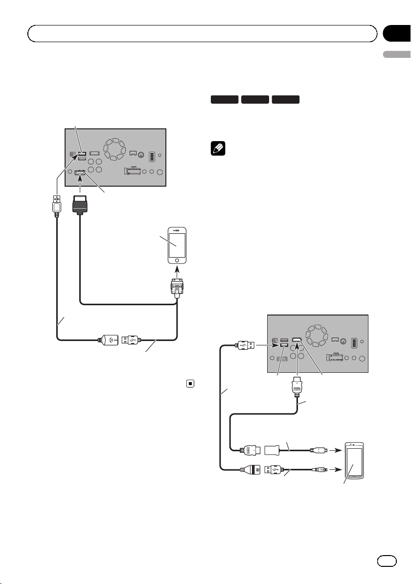
Connecting via the RGB input
The USB interface cable for iPod / iPhone (CDIU201S) (sold separately) is required for the
connection.
USB port 1
USB cable
1.5 m (4 ft. 11 in.)
This product
RGB input
iPhone with
30-pin connector
Connecting the Android
™
device
8100NEX 7100NEX
App Connectivity Kit (CD-AH200) (sold separately) is required for the connection.
Notes
! For details on how to connect an external de-
vice using a separately sold cable, refer to the
manual for the cable.
! For details concerning the connection and op-
erations of Android device, refer to Operation
Manual.
! When you connect the High Speed HDMI
Cable, use the lock tie to fix it securely.
= For details, refer to Securing the High
Speed HDMI
Connecting an Android device
with an HDMI port
6100NEX
®
Cable on page 21.
®
This product
English
USB interface cable for iPod / iPhone
(CD-IU201S) (sold separately)
USB port 2
USB cable
(supplied with
CD-AH200)
Adapter cable
(HDMI Type A - D)
(supplied with CD-AH200)
USB - micro USB cable
(Type USB A - micro USB B)
(supplied with CD-AH200)
HDMI port
High Speed HDMI®
Cable (Type A - A)
(supplied with
CD-AH200)
Android device
En
19
Section
02
Connection
Connecting an Android device
with an MHL port
This product
USB port 2
USB cable
(supplied with
CD-AH200)
High Speed HDMI® Cable
(Type A - A)
(supplied with CD-AH200)
MHL adapter
(supplied with
CD-AH200)
USB - micro USB cable
(Type USB A - micro USB B)
(supplied with CD-AH200)
HDMI port
Android device
Connecting the Android or
™
MirrorLink
The USB interface cable for use with Android
or MirrorLink
rately) is required for the connection.
USB port 2
USB cable
(supplied with CD-MU200)
USB - micro USB cable
(Type USB A - micro USB B)
(supplied with CD-MU200)
device
™
devices (CD-MU200) (sold sepa-
This product
Android or MirrorLink device
20
Note
For details on how to connect an external device
using a separately sold cable, refer to the manual
for the cable.
En
Connection
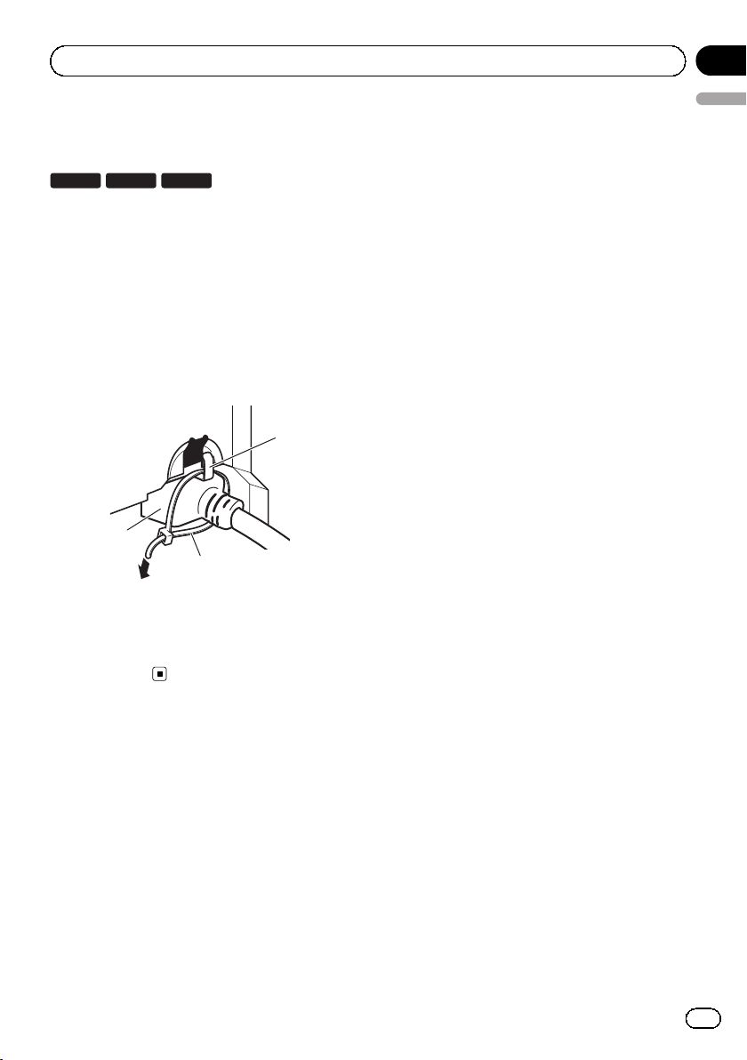
Securing the High Speed
®
HDMI
8100NEX 7100NEX
Be sure to fix the High Speed HDMI®Cable
with the lock tie, when you connect the external device with the High Speed HDMI
1 Insert the High Speed HDMI
the HDMI port.
2 Wrap the lock tie around the hook
above the HDMI port and the High Speed
HDMI
the High Speed HDMI
Cable
6100NEX
®
Cable.
®
Cable into
®
Cable, and then tighten it to secure
3
®
2
Cable.
1
Section
02
English
1 Hook
2 Lock tie
3 High Speed HDMI
p Do not tighten up the lock tie more than
necessary.
®
Cable
En
21
Section
02
Connection
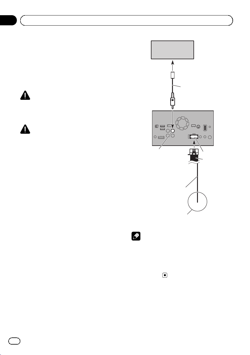
Connecting a rear view camera
When this product is used with a rear view
camera, it is possible to automatically switch
from the video to rear view image when the
shift lever is moved to REVERSE (R). Camera
View mode also allows you to check what is
behind you while driving.
WARNING
USE INPUT ONLY FOR REVERSE OR MIRROR
IMAGE REAR VIEW CAMERA. OTHER USE MAY
RESULT IN INJURY OR DAMAGE.
CAUTION
! The screen image may appear reversed.
! The rear view camera is used as an aid to
keep an eye on trailers, or backing into a tight
parking spot. Do not use this function for entertainment purposes.
! Objects in rear view may appear closer or
more distant than in reality.
! Please note that the image area shown by the
rear view camera may differ slightly when fullscreen images are displayed when backing
and when checking the rear of the vehicle
while moving forward.
Rear view camera
(ND-BC6)
(sold separately)
To video output
Brown (BC IN)
Violet/white
(REVERSE-GEAR SIGNAL
INPUT)
RCA cable
(supplied with ND-BC6)
This product
Power supply
Power cord
22
For more details about the wiring, refer to Connecting
the power cord (2) on page 10.
Notes
! This mode is available when the rear view
camera setting is set to “On”. (For details,
refer to Operation Manual.)
! Connect this product to the rear view camera
only. Do not connect to any other
equipment.
En
 Loading...