

Page 1
E-STOP relays, safety gate monitors
InputInput
A1 A2
K1
K2
14 24
S21 S22
S33 S34
=
Power
K3
K4
47 57
48 58
Reset
t
S31 S32
Input
Reset/
Start
Y39 Y40
Reset/
Start
S13 S14
S11 S12
=
34
13 23
33
Up to PL e of EN ISO 13849-1
PNOZ XV3.3P
Gertebild
][Bildunterschrift
Safety relay for monitoring E-STOP
pushbuttons and safety gates.
Approvals
PNOZ XV3.3P
Zulassungen
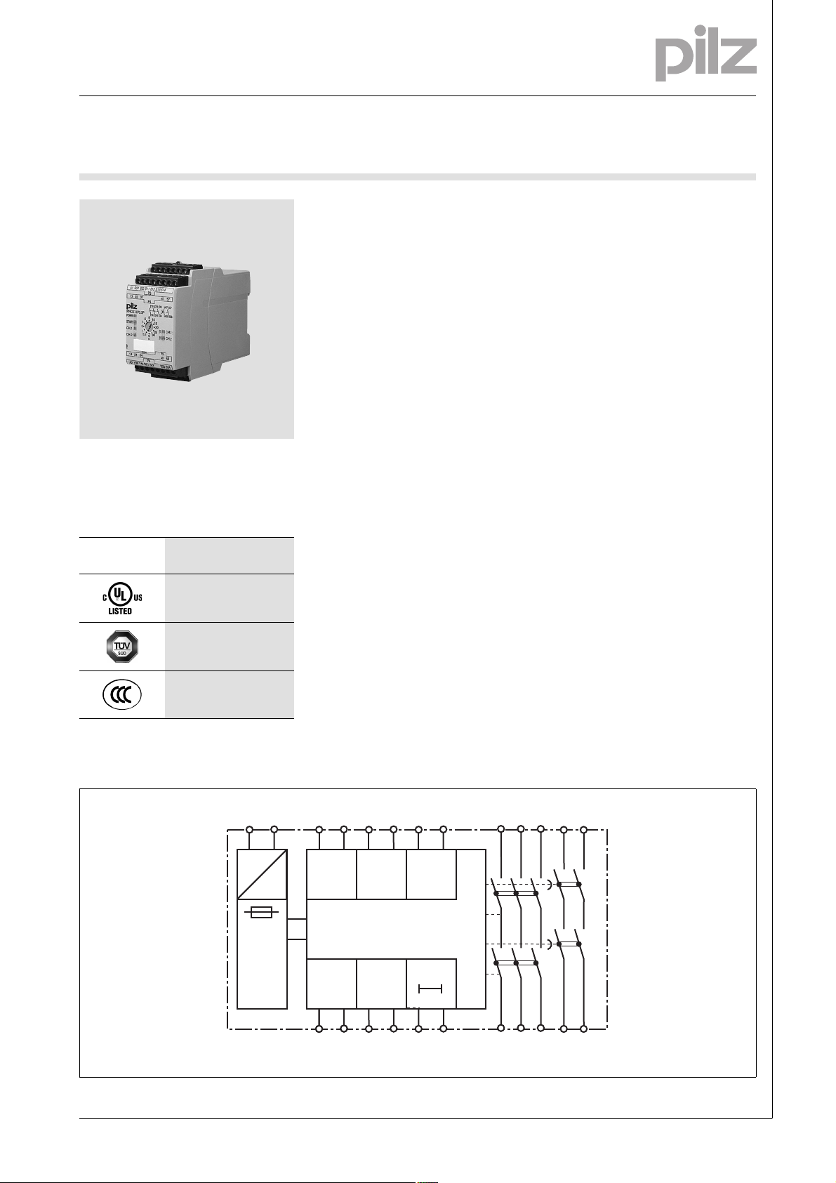
Unit features
Gertemerkmale
Positive-guided relay outputs:
– 3 safety contacts (N/O), instanta-
neous
– 2 safety contacts (N/O), delay-on
de-energisation
Connection options for:
– E-STOP pushbutton
– Safety gate limit switch
– Reset button
Delay-on de-energisation, fixed or
adjustable
Delay time can be cancelled via re-
set button
LED indicator for:
– Switch status channel 1/2
– Supply voltage
– Reset circuit
Plug-in connection terminals (either
spring-loaded terminal or screw
terminal)
See order reference for unit types
Unit description
Bestimmung/G erätebeschr eibung NOT- AUS, Schutz _PNOZ
The safety relay meets the requirements of EN 60947-5-1, EN 60204-1
and VDE 0113-1 and may be used in
applications with
E-STOP pushbuttons
Safety gates
Bestimmung/G erätebesch reibung_Ka tegorie_PN OZ
The max. category the safety contacts
can achieve in accordance with
EN 954-1 and EN ISO 13849-1 is stated in the technical details.
Safety features
][Sicherheitseigenscha ften Schaltgerät_allgem einer Teil
The relay meets the following safety
requirements:
The circuit is redundant with built-in
self-monitoring.
The safety function remains effec-
tive in the case of a component failure.
The correct opening and closing of
the safety function relays is tested
automatically in each on-off cycle.
Sicherheitseigenschaften Zusatz - Sicherung DC_PNOZ
The unit has an electronic fuse.
Block diagram
Blockschaltbild
1002309-EN-02-2011-12
Page 2
E-STOP relays, safety gate monitors
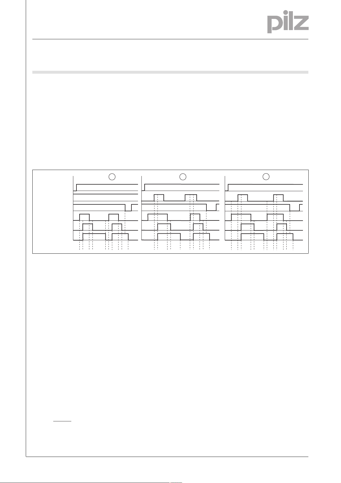
POWER
Input
Output safe del
t1 t2
t1
t2
t2t1
t3 t2
1 2
Output safe
Reset/Start
Reset t
v
t3
t1
t4
t3 t4 t3
t1
t2
t2t1
3
t3 t3
R
lmax
Rl / km
I
max
=
Up to PL e of EN ISO 13849-1
PNOZ XV3.3P
Function description
][Funktionen_einkanalig
Single-channel operation: no re-
dundancy in the input circuit, earth
faults in the reset and input circuit
are detected.
][Funktionen_zweikanalig_mit_quer_ber
Dual-channel operation with detec-
tion of shorts across contacts: redundant input circuit, detects
– earth faults in the reset and input
circuit,
Timing diagram
– short circuits in the input circuit
and, with a monitored reset, in
the reset circuit too,
– shorts between contacts in the
input circuit.
][Funktionen_autoStart
Automatic start: Unit is active once
the input circuit has been closed.
][Funktionen_manuStart
Manual reset: Unit is active once
the input circuit is closed and then
the reset circuit is closed.
][Funktionen_berStart_Wartezeit
][Zeitdiagramm_auto_manu_ueber2_del
Monitored reset: Unit is active once
the input circuit is closed and once
the reset circuit is closed after the
waiting period has elapsed
(see technical details).
][Funktionen_Kontaktvervielfachung
Increase in the number of available
instantaneous safety contacts by
connecting contact expansion
modules or external contactors.
Key
Power: Supply voltage
Reset/start: Reset circuit S13-S14,
S33-S34
Input: Input circuits S11-S12, S21-
S22, S31-S32
Output safe: Safety contacts, in-
stantaneous 13-14, 23-24, 33-34
Wiring
][Verdrahtung_Si_unverz_verz
Please note:
Information given in the “Technical
details” must be followed.
Outputs 13-14, 23-24, 33-34 are in-
stantaneous safety contacts, outputs 47-48, 57-58 are delay-on deenergisation safety contacts.
To prevent contact welding, a fuse
should be connected before the
output contacts (see technical details).
Calculation of the max. cable runs
in the input circuit:
l
max
R
= max. overall cable resist-
lmax
ance (see technical details)
Output safe del: Safety contacts,
delayed 47-48, 57-58
: Automatic reset
: Manual reset
: Monitored reset
a: Input circuit closes before reset
circuit
Rl / km = cable resistance/km
Use copper wire that can withstand
60/75 °C.
Sufficient fuse protection must be
provided on all output contacts with
capacitive and inductive loads.
b: Reset circuit closes before input
circuit
: Switch-on delay
t
1
: Delay-on de-energisation
t
2
: Delay time
t
3
t
: Waiting period
4
1002309-EN-02-2011-12
-2
Page 3
E-STOP relays, safety gate monitors
A1
L+
A2
L-
S1
S22
S21
S12
S32
S11
S31
S1
S22
S31
S32
S21
S12
S11
S1
S22
S21
S12
S32
S11
S31
S1
S2
S12
S11
S22
S32
S21
S31
Up to PL e of EN ISO 13849-1
PNOZ XV3.3P
Preparing for operation
Betriebsbereitschaft her stellen
Supply voltage
Supply voltage AC DC
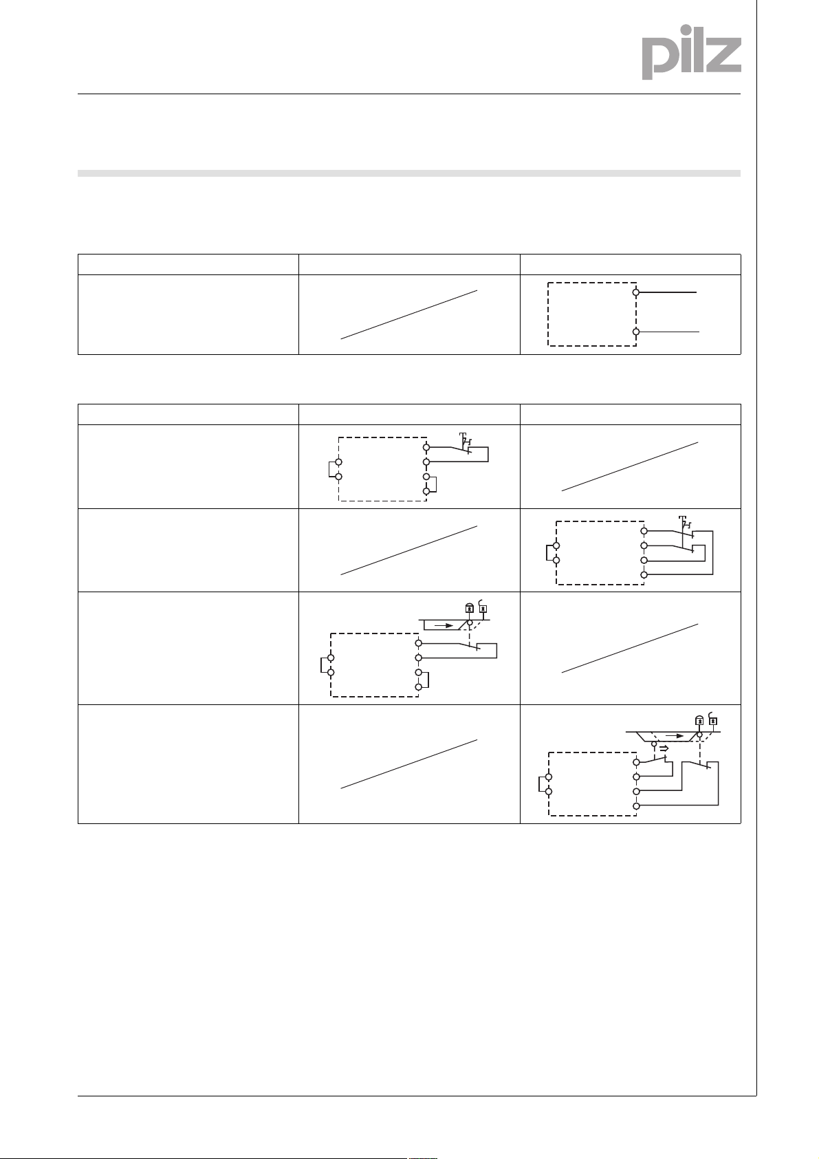
Input circuit
Input circuit Single-channel Dual-channel
E-STOP
without detection of shorts across contacts
E-STOP
with detection of shorts across contacts
Safety gate
without detection of shorts across contacts
Safety gate
with detection of shorts across contacts
1002309-EN-02-2011-12
Page 4

E-STOP relays, safety gate monitors
S13
S14
S13
S14
S33
S34
S3
S33
S34
S3
S13
S14
S3
S13
S14
S3
K5
K6
K5
L1
N
K6
S13
13 (23, 33)
S14
14 (24, 34)
K5
K6
K5
L1
K6
S33
S34
S3
N
13 (23, 33)
14 (24 ,34)
Y39
Y40
Y39
Y40
Up to PL e of EN ISO 13849-1
PNOZ XV3.3P
Reset circuit
Reset circuit E-STOP wiring (single-channel)
Safety gate (single-channel)
E-STOP wiring (dual-channel)
Safety gate (dual-channel)
Automatic reset
Monitored reset
Manual reset
Feedback loop
Feedback loop Automatic reset Monitored reset
Contacts from external contactors
Reset delay time
Reset Without reset With reset
Link or N/C contact
Key
S1/S2 E-STOP/safety gate switch
S3 Reset button
Switch operated
Gate open
Gate closed
1002309-EN-02-2011-12
-4
Page 5

E-STOP relays, safety gate monitors
17287
PNOZ XV3.3P
S22
Y39
S21
Y40 S33 S34
A2
P4
P3
P4
P3
5848
47 57
S31A1S32 S14
S12S11
S13
23 33
2414
s
CH.1
CH.2
START
POWER
[t] CH.1
CH.2 [t]
34
3323
24
5747
58
48
0
8
0,5
1
4
2
6
25
30
15
20
10
13
14
13
34
45
(1.77")
121 (4.76")
* 101 (3.98")
94 (3.70")
Up to PL e of EN ISO 13849-1
PNOZ XV3.3P
Terminal configuration
Klemmenbelegung
Installation
Montage_PNOZ_X
The safety relay should be installed
in a control cabinet with a protection type of at least IP54.
Use the notch on the rear of the unit
to attach it to a DIN rail.
Ensure the unit is mounted securely
on a vertical DIN rail (35 mm) by using a fixing element (e.g. retaining
bracket or an end angle).
Dimensions
Abmessungen
*with spring-loaded terminals
1002309-EN-02-2011-12
Page 6

E-STOP relays, safety gate monitors
Up to PL e of EN ISO 13849-1
PNOZ XV3.3P
Notice
][Wichtig_PDB
This data sheet is only intended for use
during configuration. Please refer to
the operating manual for installation
and operation.
Service life graph
Lebensdauerkurve_Rela is_Text vor Kurv e
The service life graphs indicate the
number of cycles from which failures
due to wear must be expected. The
wear is mainly caused by the electrical
load; the mechanical load is negligible.
Lebensdauerkurve_Relais_Text nach Kurve_SIR_SLR Bsp
Example
Inductive load: 0,2 A
Utilisation category: AC15
Contact service life: 4,000,000 cy-
cles
Provided the application requires fewer than 4,000,000 cycles, the PFH value (see technical details) can be used
in the calculation.
To increase the service life, sufficient
spark suppression must be provided
on all output contacts. With capacitive
loads, any power surges that occur
must be noted. With contactors, use
freewheel diodes for spark suppression.
Lebensdauerkurve
][Technische Daten PNO Z
Technical details
Electrical data
Supply voltage
Supply voltage U
Voltage tolerance -15 %/+10 %
Power consumption at U
Residual ripple DC 160 %
Voltage and current at
Input circuit DC: 24.0 V 35.0 mA
Reset circuit DC: 24.0 V 50.0 mA
Feedback loop DC: 24.0 V 3.5 mA
Number of output contacts
Safety contacts (S) instantaneous: 3
Safety contacts (N/O), delayed: 2
DC 24 V
B
DC 4.5 W
B
1002309-EN-02-2011-12
-6
Page 7

E-STOP relays, safety gate monitors
Up to PL e of EN ISO 13849-1
PNOZ XV3.3P
Electrical data
Utilisation category in accordance with EN 60947-4-1
Safety contacts: AC1 at 240 V I
Safety contacts: DC1 at 24 V I
Safety contacts, delayed: AC1 at 240 V I
Safety contacts, delayed: DC1 at 24 V I
: 0.01 A , I
min
P
: 2000 VA
max
: 0.01 A , I
min
: 200 W
P
max
: 0.01 A , I
min
: 2000 VA
P
max
: 0.01 A , I
min
P
: 200 W
max
Utilisation category in accordance with EN 60947-5-1
Safety contacts: AC15 at 230 V I
Safety contacts: DC13 at 24 V (6 cycles/min) I
Safety contacts, delayed: AC15 at 230 V I
Safety contacts, delayed: DC13 at 24 V (6 cycles/min) I
max
max
max
max
: 5.0 A
: 7.0 A
: 5.0 A
: 7.0 A
Contact material AgSnO2 + 0.2 µm Au
External contact fuse protection (I
= 1 kA) to EN 60947-5-1
K
Blow-out fuse, quick
Safety contacts: 10 A
Safety contacts, delayed: 10 A
Blow-out fuse, slow
Safety contacts: 6 A
Safety contacts, delayed: 6 A
Circuit breaker 24 VAC/DC, characteristic B/C
Safety contacts: 6 A
Safety contacts, delayed: 6 A
Max. overall cable resistance R
input circuits, reset circuits
single-channel at U
DC 100 Ohm
B
dual-channel with detect. of shorts across contacts at U
lmax
DC 10 Ohm
B
Min. input resistance when switching on 135 Ohm
Safety-related characteristic data
PL in accordance with EN ISO 13849-1: 2006
Safety contacts, instantaneous PL e (Cat. 4)
Safety contacts, delayed <30 s PL d (Cat. 3)
Safety contacts, delayed ≥30 s PL c (Cat. 1)
Category in accordance with EN 954-1
Safety contacts, instantaneous Cat. 4
Safety contacts, delayed <30 s Cat. 3
Safety contacts, delayed ≥30 s Cat. 1
SIL CL in accordance with EN IEC 62061
Safety contacts, instantaneous SIL CL 3
Safety contacts, delayed <30 s SIL CL 3
Safety contacts, delayed ≥30 s SIL CL 1
PFH in accordance with EN IEC 62061
Safety contacts, instantaneous 2.31E-09
Safety contacts, delayed <30 s 2.64E-09
Safety contacts, delayed ≥30 s 2.87E-09
SIL in accordance with IEC 61511
Safety contacts, instantaneous SIL 3
Safety contacts, delayed <30 s SIL 3
Safety contacts, delayed ≥30 s SIL 2
PFD in accordance with IEC 61511
Safety contacts, instantaneous 2.03E-06
Safety contacts, delayed <30 s 1.26E-05
Safety contacts, delayed ≥30 s 4.64E-05
T
[year] in accordance with EN ISO 13849-1: 2006 20
M
max
max
max
max
: 8.0 A
: 8.0 A
: 8.0 A
: 8.0 A
1002309-EN-02-2011-12
Page 8

E-STOP relays, safety gate monitors
Up to PL e of EN ISO 13849-1
PNOZ XV3.3P
Times
Switch-on delay
with automatic reset typ. 350 ms
with automatic reset max. 650 ms
with automatic reset after power on typ. 385 ms
with automatic reset after power on max. 700 ms
with manual reset typ. 220 ms
with manual reset max. 650 ms
on monitored reset with rising edge typ. 35 ms
on monitored reset with rising edge max. 70 ms
Delay-on de-energisation
with E-STOP typ. 15 ms
with E-STOP max. 30 ms
with power failure typ. 85 ms
with power failure max. 200 ms
Recovery time at max. switching frequency 1/s
after E-STOP 50 ms +tv
after power failure 250 ms
Delay time t
Repetition accuracy 2 %
Time accuracy -15 %/+15 % +50 ms
Waiting period with a monitored reset
with rising edge 300 ms
Min. start pulse duration with a monitored reset
with rising edge 30 ms
Simultaneity, channel 1 and 2 ∞
Supply interruption before de-energisation 20 ms
Environmental data
EMC EN 60947-5-1, EN 61000-6-2
Vibration to EN 60068-2-6
Frequency 10 - 55 Hz
Amplitude 0.35 mm
Climatic suitability EN 60068-2-78
Airgap creepage in accordance with EN 60947-1
Pollution degree 2
Overvoltage category III / II
Rated insulation voltage 250 V
Rated impulse withstand voltage 4.00 kV
Ambient temperature -10 - 55 °C
Storage temperature -40 - 85 °C
Protection type
Mounting (e.g. cabinet) IP54
Housing IP40
Terminals IP20
Mechanical data
Housing material
Housing PPO UL 94 V0
Front ABS UL 94 V0
Cross section of external conductors with screw terminals
1 core flexible 0.25 - 2.50 mm² , 24 - 12 AWG No. 777511
2 core, same cross section, flexible:
with crimp connectors, without insulating sleeve 0.25 - 1.00 mm² , 24 - 16 AWG No. 777511
without crimp connectors or with TWIN crimp connectors 0.20 - 1.50 mm² , 24 - 16 AWG No. 777511
Torque setting with screw terminals 0.50 Nm No. 777511
: selectable 0,00 s; 0,50 s; 1,00 s; 2,00 s; 4,00 s; 6,00 s; 8,00 s; 10,00 s; 15,00
V
s; 20,00 s; 25,00 s; 30,00 s No. 777511
0,00 s; 0,50 s; 1,00 s; 2,00 s; 4,00 s; 6,00 s; 8,00 s; 10,00 s; 15,00
s; 20,00 s; 25,00 s; 30,00 s No. 787511
1002309-EN-02-2011-12
-8
Page 9

E-STOP relays, safety gate monitors
Up to PL e of EN ISO 13849-1
PNOZ XV3.3P
Mechanical data
Cross section of external conductors with spring-loaded terminals: Flexible with/without crimp connectors
Spring-loaded terminals: Terminal points per connection 2 No. 787511
Stripping length 8 mm No. 787511
Dimensions
Height 101.0 mm No. 787511
Width 45.0 mm
Depth 121.0 mm
Weight 364 g No. 787511
Technische Daten_Satz No .
No. stands for order number.
Si-Kennzahlen_Zusatz_Relais_Lebensdauer_PDB
It is essential to consider the relay's
service life graphs. The relay outputs'
safety-related characteristic data is
only valid if the values in the service life
graphs are met.
The PFH value depends on the switching frequency and the load on the relay
output.
If the service life graphs are not accessible, the stated PFH value can be
All the units used within a safety function must be considered when calculating the safety characteristic data.
0.20 - 1.50 mm² , 24 - 16 AWG No. 787511
94.0 mm No. 777511
375 g No. 777511
used irrespective of the switching frequency and the load, as the PFH value
already considers the relay's B10d value as well as the failure rates of the
other components.
Si_Kennzahlen_Erläute rung_1
Si_Kennzahlen_Erläuterung_2
INFORMATION
A safety function's SIL/PL values are
not identical to the SIL/PL values of
the units that are used and may be different. We recommend that you use
the PAScal software tool to calculate
the safety function's SIL/PL values.
The standards current on 2010-07 apply.
][Dauerstrom_DC
Conventional thermal current while loading several contacts
Number of contacts I
1 8.00 A
2 6.80 A
3 5.50 A
4 4.80 A
5 4.30 A
Order reference
Type Features Terminals Order no.
PNOZ XV3.3P C 24 VDC 30 s selectable Spring-loaded terminals 787 511
PNOZ XV3.3P 24 VDC 30 s selectable Screw terminals 777 511
per contact at UBDC
th
Bestelldaten
Technische Daten_Satz Normen
1002309-EN-02-2011-12
 Loading...