

Page 1
Emergency Stop Relays, Safety Gate Monitors
Category 4, EN 954-1
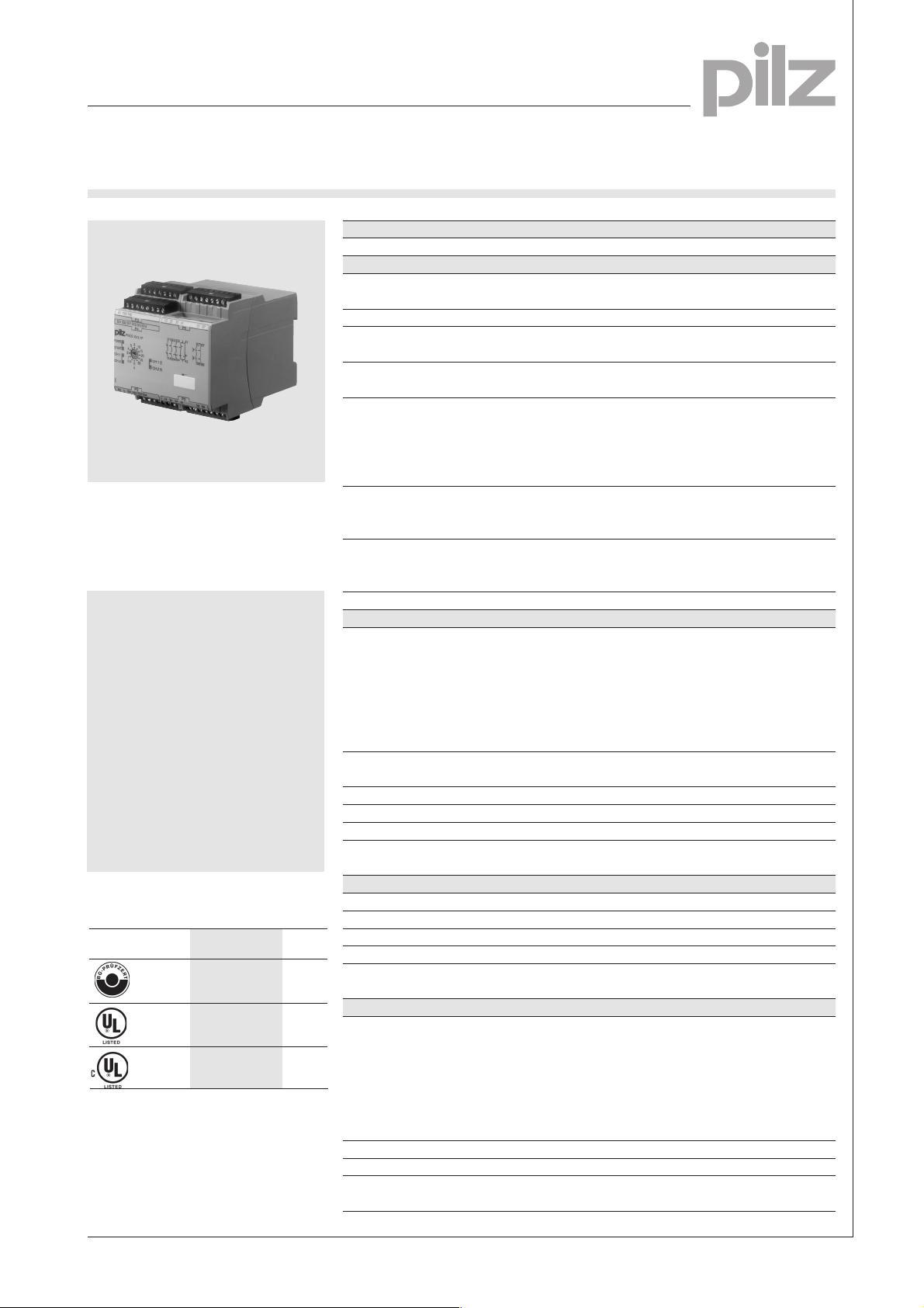
PNOZ XV3.1P
Technical Details PNOZ XV3.1P
Electrical Data
Supply Voltage DC: 24 V DC
AC/DC: 24 V ... 240 V
Tolerance 85 ... 110 %
DC: Approx. 4,5 W
AC/DC: Approx. 11 VA/5.5 W
DC1: 24 V/0,03...5 A/120 W
1 auxiliary contact (N/C)
3 instantaneous safety contacts (N/O)
Characteristic B/C
0,1-3 s: 0.1/0.2/0.3/0.4/0.5/0.6/0.7/0.8/
1/1.5/2/3 s
0-30 s: 0/0.5/1/2/4/6/8/10/15/20/25/30 s
0-300: 0/5/10/20/40/60/80/100/150/200/
250/300 s
Fixed: 0.5 s/3 s/10 s
Automatic or manual Reset. Max. 0.5 s
Flexible, without crimp connectors: 0.2 ... 1.5 mm
AC/DC: 595 g
Flexible, without crimp connectors: 0.2 ... 2.5 mm
Flexible with crimp connectors: 0.25 ... 2.5 mm
Flexible, with TWIN-crimp connectors
and plastic sheath: 0.5 ... 1.5 mm
AC/DC: 595 g
Emergency stop relay and safety
gate monitor in accordance with
EN 60204-1 (VDE 0113 part 1), 12/97
and IEC 60204-1, 10/97
Features
● Dual-channel wiring with
detection of shorts across the
input contacts
● Monitored manual or automatic
reset can be selected
● 2 delay-off safety contacts
● Supply voltage:
24 ... 240 V AC/DC
● Supply voltage:
24 V DC
l Plug-in connection terminals
(Either screw terminals or cage
clamp terminals)
Approvals
PNOZ XV3.1P
●
●
●
Power Consumption U
Voltage and Current at the Input and DC: 24 V DC, 50 mA
Reset Circuits and Feedback Control Loop AC/DC: 22 V DC, 50 mA
Switching Capability in accordance with
EN 60947-4-1, 02/01 AC1: 240 V/0,03...5 A/1200 VA
EN 60947-5-1, 11/97 AC15: 230 V/5 A; DC13: 24 V/3 A
(DC13: 6 cycles/min.)
Output Contacts 2 delayed safety contacts (N/O)
Contact fuse protection according to Blow-out fuse: 6 A
EN 60947-5-1, 11/97 Safety cut-out: 24 V DC: 6 A,
EMC EN 61000-6-3, 10/01, EN 61000-6-2, 10/01
Times
Delay-on-De-Energisation 57-58, 67-68 Adjustable:
Switch-on delay Monitored Reset: Max. 100 ms
Delay-on De-energisation Max. 50 ms
Recovery Time Approx. 1 s
Simultaneity channel1/2 ¥
Max. Supply Interruption before Approx. 25 ms
De-energisation
Mechanical Data: with cage clamp terminals
Terminal blocks per connection 2
Maximum cross section of ext. conductors
Stripping length 8 mm
Dimensions (H x W x D) 101 x90 x 121 mm
Weight DC: 510 g
Mechanical Data: with screw terminals
Maximum cross section of ext. conductors
Single-core
Multi-core Flexible, with crimp connectors but
(2 conductors with same cross-section) without plastic sheath: 0.25 ... 1 mm
Torque setting for screw terminals 0.5 ... 0.6 Nm
Dimensions (H x W x D) 94 x 90 x 121 mm
Weight DC: 510 g
B
quick or
4 A
1
slow
2
2
2
2
2
NSG-D-2-298-10/03
1-1
Page 2

Emergency Stop Relays, Safety Gate Monitors
S12
S14
S13
S11
S21
S32
S22
S1
S2
S31
Y39
Y40
S12
S34
S33
S11
S21
S32
S22
S31
S1
S2
S3
Y39
Y40
Category 4, EN 954-1
PNOZ XV3.1P
1
Description
● 90 mm P-99 housing, DIN Rail
mounting
● Positive-guided relay outputs:
– 3 instantaneous safety
contacts (N/O)
–
1 auxiliary contact (N/C)
– 2 delayed safety contacts
(N/O)
● Connections for
– E-STOP button
– safety gate limit switch
– reset button
Internal Wiring Diagram
B
Time reset Input circuit Auxiliary
U
A2
A1
Y40
Power
only on
AC/DC-device
feedback control loop
Y39
CH2
S21
Reset circuit and
S33
S34
Input circuit
● LEDs for power, channel 1,
channel 2, reset circuit
● Increase in the number of
safety contacts available by
connecting expander modules.
Operating Modes
● Single-channel operation
● Dual-channel operation
● Automatic reset
● Monitored manual reset
Safety
contacts
S31
S12
S32
13 57
S14
Start
Unit
S13
S11
CH1
S22
23
K1
K2
14 58
24
232441
contact
42
K3
K4
Safety
contacts
● Example 3
Dual-channel E-STOP wiring with
monitored manual reset.
S21 S11
S31
S1
S12
S22
S32
Y39
S33
S3
Y40
S34
● Example 4
Single-channel safety gate control
with monitored manual reset.
S11
S21
S31
67
S12
S1
S32
S22
Y39
S33
S3
Y40
S34
● Example 5
68
Dual-channel safety gate control with
monitored manual reset.
External Wiring
● Example 1
Single-channel E-STOP wiring with
automatic reset.
S11 S31
S21
S1
S32
S12
S22
S13
S14
Y39
Y40
● Example 2
Single-channel E-STOP wiring with
monitored manual reset.
S11 S31
S21
Y39
S33
S1
S12
S32
S22
S3
Y40
S34
● Example 6
Dual-channel safety gate control with
automatic reset.
NSG-D-2-298-10/03
Page 3

Emergency Stop Relays, Safety Gate Monitors
Category 4, EN 954-1
PNOZ XV3.1P
● Example 7
Dual channel light barrier control with
shorts across contacts detection by
BWS, with monitored start
BWS
S11
24 V DC
S12 S22 S34S32
S33S21S31
S3
– Key
S1/2: E-STOP or safety gate switch
S3: Reset button
Switch operated
Gate open
Gate closed
● Increase in safety contacts
The number of output contacts can
be increased by using expander
modules or relays/contactors with
positive-guided contacts.
– Operation with automatic reset.
1L1
K7
K8
S13
1L2
K5
K6
13
S14
14
K5
K6
57
58
K8
K7
– Operation with monitored manual
reset.
1
1L1
K7
K8
S33
1L2
K5
K6
S3
13
S34
14
K5
K6
57
58
K8
K7
NSG-D-2-298-10/03
1-3
Page 4

1
Emergency Stop Relays, Safety Gate Monitors
Category 4, EN 954-1
PNOZ XV3.1P
General Technical Data
Unless stated otherwise in the technical details for the specific unit
Electrical Data
Frequency Range AC 50 ... 60 Hz
Residual Ripple DC 160 %
Contact Material AgSnO
Continuous Duty 100 %
Environmental Data
EMC EN 50081-1, 01/92, EN 61000-6-2, 10/01
Vibration in accordance with Frequency: 10 ... 55 Hz,
EN 60068-2-6, 04/95 Amplitude: 0.35 mm
Climatic Suitability DIN IEC 60068-2-3, 12/86
Airgap Creepage DIN VDE 0110-1, 04/97
Ambient Temperature -10 ... +55 °C
Storage Temperature -40 ... +85 °C
Mechanical Data
Torque Setting on Connection Terminals 0.6 Nm (screws)
Mounting Position Any
Housing Material Thermoplast Noryl SE 100
Protection Mounting: IP 54
2
Housing: IP 40
Terminal Range: IP 20
The units were tested in accordance with the relevant standards current at
the time of development.
Order References
Type t U
PNOZ XV3.1P cage clamp terminals 0,5 s fixed 24 V DC 787 524
PNOZ XV3.1P screw terminals 0,5 s fixed 24 V DC 777 524
PNOZ XV3.1P cage clamp terminals 3 s fixed 24 V DC 787 525
PNOZ XV3.1P screw terminals 3 s fixed 24 V DC 777 525
PNOZ XV3.1P cage clamp terminals 10 s fixed 24 V DC 787 527
PNOZ XV3.1P screw terminals 10 s fixed 24 V DC 777 527
PNOZ XV3.1P cage clamp terminals 3 s adjustable 24 V DC 787 522
PNOZ XV3.1P screw terminals 3 s adjustable 24 V DC 777 522
PNOZ XV3.1P cage clamp terminals 30 s adjustab. 24 V DC 787 520
PNOZ XV3.1P screw terminals 30 s adjustab. 24 V DC 777 520
PNOZ XV3.1P cage clamp terminals 300 s adjustab.24 V DC 787 528
PNOZ XV3.1P screw terminals 300 s adjustab.24 V DC 777 528
PNOZ XV3.1P cage clamp terminals 0,5 s fixed 24 V ... 240 V AC/DC 787 534
PNOZ XV3.1P screw terminals 0,5 s fixed 24 V ... 240 V AC/DC 777 534
PNOZ XV3.1P cage clamp terminals 3 s fixed 24 V ... 240 V AC/DC 787 535
PNOZ XV3.1P screw terminals 3 s fixed 24 V ... 240 V AC/DC 777 535
PNOZ XV3.1P cage clamp terminals 10 s fixed 24 V ... 240 V AC/DC 787 537
PNOZ XV3.1P screw terminals 10 s fixed 24 V ... 240 V AC/DC 777 537
PNOZ XV3.1P cage clamp terminals 3 s adjustable 24 V ... 240 V AC/DC 787 532
PNOZ XV3.1P screw terminals 3 s adjustable 24 V ... 240 V AC/DC 777 532
PNOZ XV3.1P cage clamp terminals 30 s adjustab. 24 V ... 240 V AC/DC 787 530
PNOZ XV3.1P screw terminals 30 s adjustab. 24 V ... 240 V AC/DC 777 530
PNOZ XV3.1P cage clamp terminals 300 s adjustab.24 V ... 240 V AC/DC 787 538
PNOZ XV3.1P screw terminals 300 s adjustab. 24 V ... 240 V AC/DC 777 538
B
Order No.
NSG-D-2-298-10/03
 Loading...