

Page 1

PNOZ mc6p/mc6.1p
} Configurable safety systems PNOZmulti
Operating Manual 19864-EN-07
Page 2

Preface
This document is a translation of the original document.
All rights to this documentation are reserved by Pilz GmbH & Co. KG. Copies may be made
for internal purposes. Suggestions and comments for improving this documentation will be
gratefully received.
Source code from third-party manufacturers or open source software has been used for
some components. The relevant licence information is available on the Internet on the Pilz
homepage.
Pilz®, PIT®, PMI®, PNOZ®, Primo®, PSEN®, PSS®, PVIS®, SafetyBUS p®,
SafetyEYE®, SafetyNET p®, the spirit of safety® are registered and protected trademarks
of Pilz GmbH & Co. KG in some countries.
SD means Secure Digital
Page 3

Contents
Section 1 Introduction 5
1.1 Validity of documentation 5
1.2 Using the documentation 5
1.3 Definition of symbols 5
Section 2 Overview 7
2.1 Scope 7
2.2 Unit features 7
2.3 Front view 8
2.3.1 Key 8
Section 3 Safety 9
3.1 Intended use 9
3.2 System requirements 9
3.3 Safety regulations 10
3.3.1 Use of qualified personnel 10
3.3.2 Warranty and liability 10
3.3.3 Disposal 10
3.3.4 For your safety 11
Section 4 Function description 12
4.1 Operation 12
4.2 Input and output data 12
4.3 Assigning the inputs/outputs in the PNOZmulti Configurator to the CAN-
13
open inputs/outputs
4.4 Block diagram 13
Section 5 Installation 14
5.1 General installation guidelines 14
5.2 Dimensions in mm 14
5.3 Connecting the base unit and expansion modules 15
Section 6 Commissioning 16
6.1 General wiring guidelines 16
6.2 Connecting the supply voltage 16
6.3 CANopen interface 17
6.3.1 CANopen termination 17
6.4 Preparing for operation 17
6.4.1 Setting the transmission rate 17
6.4.2 Setting the station address 18
6.4.3 Download modified project to the PNOZmulti safety system 18
6.4.4 Connection example 19
Section 7 Operation 20
7.1 LED indicators 20
Operating Manual PNOZ mc6p/mc6.1p
19864-EN-07
3
Page 4

Contents
Section 8 Technical details 21
Section 9 Order reference 23
9.1 Product 23
9.2 Accessories 23
Operating Manual PNOZ mc6p/mc6.1p
19864-EN-07
4
Page 5
Introduction
1 Introduction
1.1 Validity of documentation
This documentation is valid for the product PNOZ mc6p/mc6.1p. It is valid until new documentation is published.
This operating manual explains the function and operation, describes the installation and
provides guidelines on how to connect the product.
1.2 Using the documentation
This document is intended for instruction. Only install and commission the product if you
have read and understood this document. The document should be retained for future reference.
1.3 Definition of symbols
Information that is particularly important is identified as follows:
DANGER!
This warning must be heeded! It warns of a hazardous situation that poses
an immediate threat of serious injury and death and indicates preventive
measures that can be taken.
WARNING!
This warning must be heeded! It warns of a hazardous situation that could
lead to serious injury and death and indicates preventive measures that can
be taken.
CAUTION!
This refers to a hazard that can lead to a less serious or minor injury plus
material damage, and also provides information on preventive measures
that can be taken.
Operating Manual PNOZ mc6p/mc6.1p
19864-EN-07
NOTICE
This describes a situation in which the product or devices could be damaged and also provides information on preventive measures that can be
taken. It also highlights areas within the text that are of particular importance.
5
Page 6

Introduction
INFORMATION
This gives advice on applications and provides information on special features.
Operating Manual PNOZ mc6p/mc6.1p
19864-EN-07
6
Page 7

Overview
2 Overview
2.1 Scope
} Expansion module PNOZ mc6p/mc6.1p
} Jumper
2.2 Unit features
Using the product PNOZ mc6p/mc6.1p:
Expansion module for connection to a base unit from the configurable control system
PNOZmulti
The product has the following features:
} Can be configured in the PNOZmulti Configurator
} Connection for CANopen
} Station addresses from 0 ... 99, selected via rotary switch
} Transmission rate selected via rotary switch (1 MBit/s, 10 kbit/s, 125 kBit/s, 20 kbit/s,
250 kBit/s, 50 kbit/s, 500 kBit/s, 800 kbit/s)
} Status indicators for communication with CANopen and for errors
} Supported protocols:
PNOZ mc6p: CiA DS-301 V3.0
PNOZ mc6.1p: CiA DS-301 V4.0.2
} PNOZ mc6.1p: Default COB-ID has been adapted for RPDO 3 (400 h) and TPDO 3
(380 h)
} 24 virtual inputs and outputs on the control system PNOZmulti can be defined in the
PNOZmulti Configurator for communication with the fieldbus CANopen . The number of
inputs and outputs can be extended to 128. Please note that when the extended inputs
and outputs 24 - 127 are used they have different properties (see document entitled
"Communication Interfaces").
} Max. 1 PNOZ mc6p/mc6.1p can be connected to the base unit
} Please refer to the document "PNOZmulti System Expansion" for the PNOZmulti base
units that can be connected.
} Coated version:
Increased environmental requirements (see Technical details [ 21])
Operating Manual PNOZ mc6p/mc6.1p
19864-EN-07
7
Page 8
Overview
CANopen
PNOZ mc6p
PWR
ERR
x1
x10
X1
RUN
DR
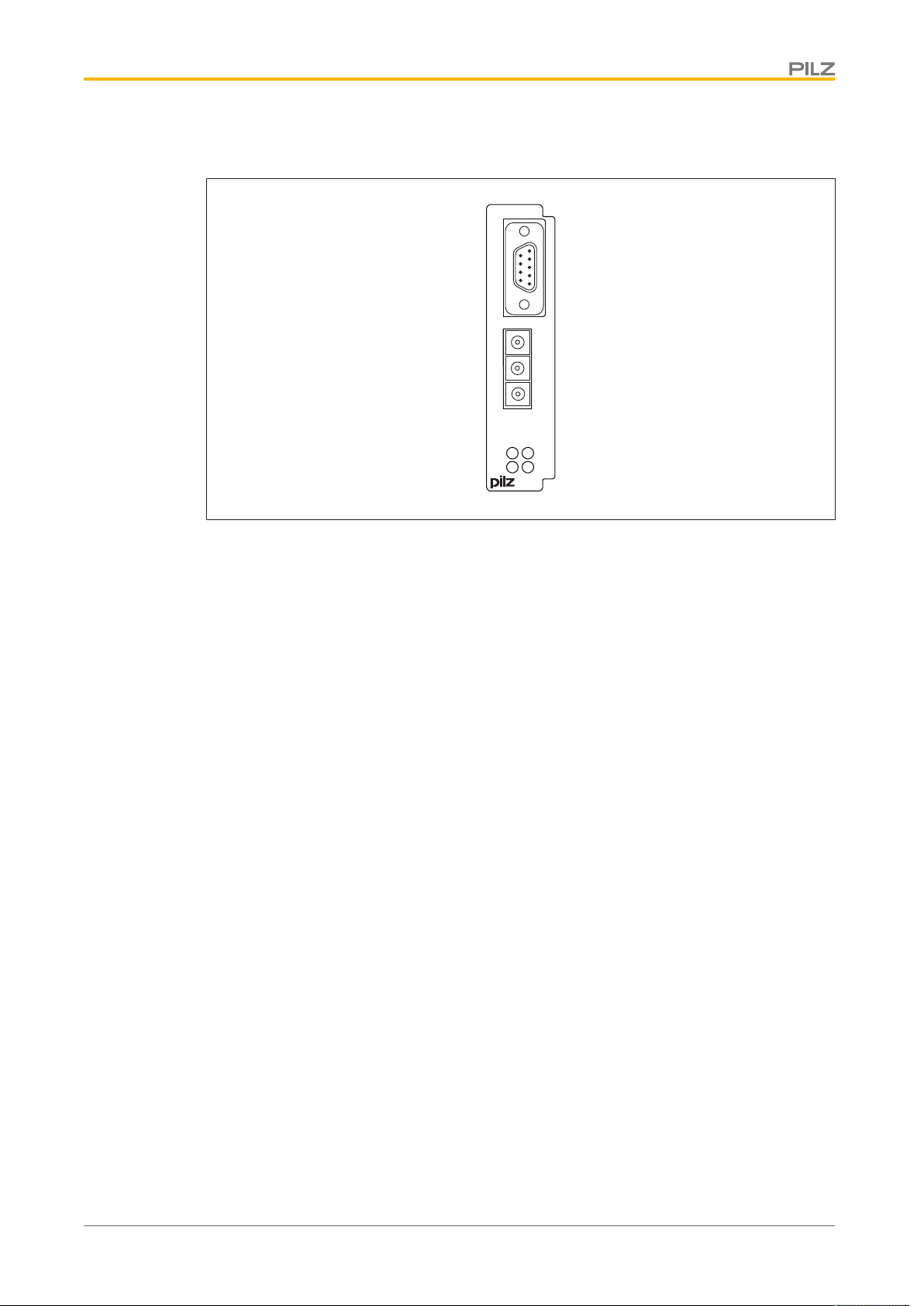
2.3 Front view
2.3.1 Key
} X1: CANopen interface (male 9-pin D-Sub connector)
} LED:
– Power
– Run
– Error
Operating Manual PNOZ mc6p/mc6.1p
19864-EN-07
8
Page 9
Safety
3 Safety
3.1 Intended use
The fieldbus module PNOZ mc6p/mc6.1p is an expansion module of the configurable control system PNOZmulti. It is used for communication between the configurable control system PNOZmulti and CANopen.
CANopen is designed for fast data exchange at field level. The expansion module PNOZ
mc6p/mc6.1p is a passive CANopen subscriber (Slave). The basic communication functions with CANopen conform to the guidelines of the CANopen User Group (CiA, for supported protocols see Technical Details). The central controller (master) reads input information from the slaves and writes output information to the slaves as part of each cycle. As
well as the cyclical transfer of usable data, the expansion module PNOZ mc6p/mc6.1p can
also be used for diagnostic and commissioning functions. Data traffic is monitored on the
Master/Slave side.
The expansion module may only be connected to a base unit from the PNOZmulti system
(please refer to the document "PNOZmulti System Expansion" for details of the base units
that can be connected).
The configurable small control systems PNOZmulti are used for the safety-related interruption of safety circuits and are designed for use in:
} E-STOP equipment
} Safety circuits in accordance with VDE0113 Part 1 and EN60204-1
The expansion module may not be used for safety-related functions.
The following is deemed improper use in particular:
} Any component, technical or electrical modification to the product
} Use of the product outside the areas described in this manual
} Use of the product outside the technical details (see Technical details [ 21]).
NOTICE
EMC-compliant electrical installation
The product is designed for use in an industrial environment. The product
may cause interference if installed in other environments. If installed in other
environments, measures should be taken to comply with the applicable
standards and directives for the respective installation site with regard to interference.
The coated version of the product PNOZ mc6p/mc6.1p is suitable for use where there are
increased environmental requirements (see Technical details [ 21]).
3.2 System requirements
Please refer to the "Product Modifications PNOZmulti" document in the "Version overview"
section for details of which versions of the base unit and PNOZmulti Configurator can be
used for this product.
Operating Manual PNOZ mc6p/mc6.1p
19864-EN-07
9
Page 10

Safety
3.3 Safety regulations
3.3.1 Use of qualified personnel
The products may only be assembled, installed, programmed, commissioned, operated,
maintained and decommissioned by competent persons.
A competent person is someone who, because of their training, experience and current professional activity, has the specialist knowledge required to test, assess and operate the
work equipment, devices, systems, plant and machinery in accordance with the general
standards and guidelines for safety technology.
It is the company’s responsibility only to employ personnel who:
} Are familiar with the basic regulations concerning health and safety / accident preven-
tion
} Have read and understood the information provided in this description under "Safety"
} And have a good knowledge of the generic and specialist standards applicable to the
specific application.
3.3.2 Warranty and liability
All claims to warranty and liability will be rendered invalid if
} The product was used contrary to the purpose for which it is intended
} Damage can be attributed to not having followed the guidelines in the manual
} Operating personnel are not suitably qualified
} Any type of modification has been made (e.g. exchanging components on the PCB
boards, soldering work etc.).
3.3.3 Disposal
} When decommissioning, please comply with local regulations regarding the disposal of
electronic devices (e.g. Electrical and Electronic Equipment Act).
Operating Manual PNOZ mc6p/mc6.1p
19864-EN-07
10
Page 11

Safety
3.3.4 For your safety
The unit meets all the necessary conditions for safe operation. However, you should always
ensure that the following safety requirements are met:
} This operating manual only describes the basic functions of the unit. The expanded
functions are described in the PNOZmulti Configurator's online help. Only use these
functions once you have read and understood the documentations.
} Do not open the housing or make any unauthorised modifications.
} Please make sure you shut down the supply voltage when performing maintenance
work (e.g. exchanging contactors).
Operating Manual PNOZ mc6p/mc6.1p
19864-EN-07
11
Page 12

Function description
4 Function description
4.1 Operation
The virtual inputs and outputs that are to be transferred via CANopen are selected and configured in the PNOZmulti Configurator. The base unit and the expansion module PNOZ
mc6p/mc6.1p are connected via a jumper. The station address and the transmission rate
are set using rotary switches. The fieldbus module is also supplied with voltage via this
jumper. After the supply voltage is switched on or the PNOZmulti control system is reset,
the expansion module PNOZ mc6p/mc6.1p is configured and started automatically.
LEDs indicate the status of the expansion module on CANopen.
The configuration is described in detail in the PNOZmulti Configurator's online help.
4.2 Input and output data
The data is structured as follows:
} Input area
The inputs are defined in the master and transferred to the PNOZmulti. Each input has
a number, e.g. input bit 4 of byte 1 has the number i12.
} Output range
The outputs are defined in the PNOZmulti Configurator. Each output that is used is
given a number there, e.g. o0, o5... The status of output o0 is stored in bit 0 of byte 0;
the status of output o5 is stored in bit 5 of byte 0 etc.
} Output range only: Byte 3
Bits 0 … 4: Status of LEDs on the PNOZmulti
– Bit 0: OFAULT
– Bit 1: IFAULT
– Bit 2: FAULT
– Bit 3: DIAG
– Bit 4: RUN
Bit 5: Data is being exchanged.
Detailed information on data exchange (tables, segments) is available in the document
"Communication Interfaces" in the section entitled "Fieldbus modules".
Operating Manual PNOZ mc6p/mc6.1p
19864-EN-07
12
Page 13

Function description
Base unit
CANopen
4.3 Assigning the inputs/outputs in the PNOZmulti Configurator to the CANopen inputs/outputs
Virtual inputs on PNOZmulti Configurator i0 ... I7 i8 ... i15 i16 ... i23
Input data CANopen Byte 0: Bits 0 … 7 Byte 1: Bits 0 … 7 Byte 2: Bits 0 … 7
Virtual outputs on PNOZmulti Configurator o0 ... o7 o8 ... o15 o16 ... o23
Output data CANopen Byte 0: Bits 0 … 7 Byte 1: Bits 0 … 7 Byte 2: Bits 0 … 7
The number of virtual inputs and outputs can be extended to 128 (see document "Communication Interfaces" in the section entitled "Fieldbus modules")
4.4 Block diagram
Operating Manual PNOZ mc6p/mc6.1p
19864-EN-07
13
Page 14

Installation
94 (3.70")
22,5
(0.88")
114 (4.49")
5 Installation
5.1 General installation guidelines
} The control system should be installed in a control cabinet with a protection type of at
least IP54. Fit the control system to a horizontal mounting rail. The venting slots must
face upward and downward. Other mounting positions could destroy the control system.
} Use the notches on the rear of the unit to attach it to a mounting rail. Connect the con-
trol system to the mounting rail in an upright position, so that the earthing springs on the
control system are pressed on to the mounting rail.
} The ambient temperature of the PNOZmulti units in the control cabinet must not exceed
the figure stated in the technical details, otherwise air conditioning will be required.
} To comply with EMC requirements, the mounting rail must have a low impedance con-
nection to the control cabinet housing.
CAUTION!
Damage due to electrostatic discharge!
Electrostatic discharge can damage components. Ensure against discharge
before touching the product, e.g. by touching an earthed, conductive surface or by wearing an earthed armband.
5.2 Dimensions in mm
Operating Manual PNOZ mc6p/mc6.1p
19864-EN-07
14
Page 15

Installation
5.3 Connecting the base unit and expansion modules
You can install a maximum of 1 PNOZ mc6p/mc6.1p to the left of the base unit.
Connect the base unit and the expansion module as described in the operating instructions
for the base units.
} Do not connect a terminator to the last expansion module on the left-hand side.
} Install the expansion module in the position in which it is configured in the PNOZmulti
Configurator.
Operating Manual PNOZ mc6p/mc6.1p
19864-EN-07
15
Page 16
Commissioning
6 Commissioning
6.1 General wiring guidelines
The wiring is defined in the circuit diagram of the PNOZmulti Configurator.
Please note:
} Information given in the Technical details [ 21] must be followed.
} Use copper wire that can withstand 75°C.
} Always connect the mounting rail to the protective earth via an earthing terminal. This
will be used to dissipate hazardous voltages in the case of a fault.
} The power supply must meet the regulations for extra low voltages with protective sep-
aration.
CAUTION!
Only connect and disconnect the expansion module when the supply
voltage is switched off.
NOTICE
When installing, you must refer to the guidelines of the CANopenUser
Group.
6.2 Connecting the supply voltage
Connect the supply voltage to the base unit:
} Terminal 24 V and A1 (+): + 24VDC
} Terminal 0 V and A2 (-): 0 V
Operating Manual PNOZ mc6p/mc6.1p
19864-EN-07
16
Page 17

Commissioning
5
1
6
9
1: n.c.
2: CAN_L
3: CAN_GND
4: n.c.
5: CAN_SHLD
6: n.c.
7: CAN_H
8: n.c.
9: n.c.
1
2
3
4
9
8
7
6
0
5
DR
6.3 CANopen interface
The connection to CANopen is made via a male 9-pin D-Sub connector.
n.c. = not connected
Please note the following when connecting to CANopen:
} Only use metal plugs or metallised plastic plugs
} Twisted pair, screened cable must be used to connect the interfaces
6.3.1 CANopen termination
To minimise cable reflection and to guarantee a defined rest signal on the transmission line,
CANopen must be terminated at both ends.
6.4 Preparing for operation
6.4.1 Setting the transmission rate
} On the upper rotary switch DR, use a small screwdriver to set the transmission rate (in
the example, "3" corresponds to 50 kBit/s).
Switch setting 0 1 2 3 4 5 6 7 8 9
Transmission rate - 10
kBit/s20kBit/s50kBit/s
Operating Manual PNOZ mc6p/mc6.1p
19864-EN-07
125
kBit/s
250
kBit/s
500
kBit/s
800
kBit/s1MBit/s
-
17
Page 18
Commissioning
1
2
3
4
9
8
7
6
0
5
x10
1
2
3
4
9
8
7
6
0
5
x1
INFORMATION
The transmission rate cannot be changed during operation.
6.4.2 Setting the station address
The station address of the expansion module PNOZ mc6p/mc6.1p is set between 0 ... 99
(decimal) via two rotary switches x1 and x10.
} On the middle rotary switch x10, use a small screwdriver to set the tens digit for the ad-
dress (“3” in the example).
} On the lower rotary switch x1, set the ones digit for the address (“6” in the example).
Station address 36 is set in the diagrams as an example.
6.4.3 Download modified project to the PNOZmulti safety system
As soon as an additional expansion module has been connected to the system, the project
must be amended using the PNOZmulti Configurator. Proceed as described in the operating instructions for the base unit.
Operating Manual PNOZ mc6p/mc6.1p
19864-EN-07
NOTICE
For the commissioning and after every program change, you must check
whether the safety devices are functioning correctly.
18
Page 19
Commissioning
CANopen
PNOZ mc6p
PWR
ERR
x1
x10
X1
RUN
DR
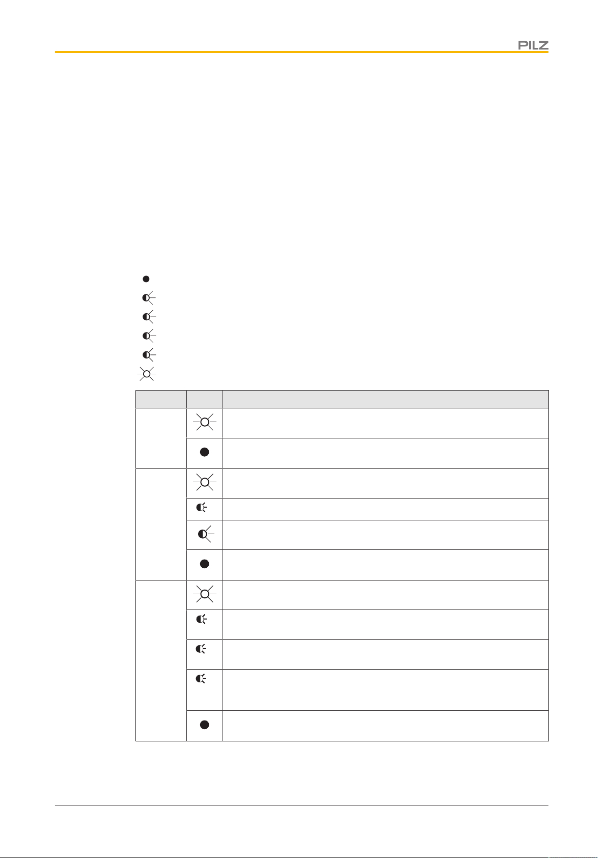
CANopen
Master
CANopen
Slave 1
CANopen
Slave 2
CANopen
Slave 3
CANopen
Slave n
PNOZ mc6p CANopen
6.4.4 Connection example
Operating Manual PNOZ mc6p/mc6.1p
19864-EN-07
19
Page 20
Operation
1
2
3
1
1
2
3
7 Operation
When the supply voltage is switched on, the PNOZmulti safety system copies the configuration from the chip card.
The LEDs “POWER”, “DIAG”, “FAULT”, “IFAULT” and “OFAULT” will light up on the base
unit.
The expansion module PNOZ mc6p/mc6.1p is configured and started automatically. The
LEDs “RUN” and “ERR” display the status of the PNOZ mc6p/mc6.1p on CANopen.
7.1 LED indicators
Legend
LED off
LED flashes
LED flashes once
LED flashes twice
LED flashes three times
LED on
LED Key
PWR Supply voltage is present
Supply voltage is not present
RUN PNOZ mc6p/mc6.1p In "Operational" status
PNOZ mc6p/mc6.1p In "Stopped" status
PNOZ mc6p/mc6.1p In "Pre-Operational" status
No supply voltage or module error detected
ERR CAN controller is in "Bus off" status
Error threshold value has been reached, the CAN controller has received too many error telegrams
Monitoring error, activation of master-slave monitoring error, e.g.
heartbeat monitoring
Error in "Synchronisation" operating status, a synchronisation telegram, e.g. with simultaneous writing on several devices, did not occur
within the configured time
No error
Operating Manual PNOZ mc6p/mc6.1p
19864-EN-07
20
Page 21

Technical details
8 Technical details
General 773712 773727 773733
CCC, CE, EAC (Eurasian), KCC, KOSHA, TÜV,
Approvals
Electrical data 773712 773727 773733
Supply voltage
for Module supply Module supply Module supply
internal Via base unit Via base unit Via base unit
Voltage 5,0 V 5,0 V 5,0 V
Kind DC DC DC
Voltage tolerance -2 %/+2 % -2 %/+2 % -2 %/+2 %
Power consumption 1,0 W 2,5 W 1,0 W
Status indicator LED LED LED
Fieldbus interface 773712 773727 773733
Fieldbus interface CANopen CANopen CANopen
Device type Slave Slave Slave
Log CiA DS-301 V3.0 CiA DS-301 V3.0 CiA DS-301 V4.02
Station address 0 - 99d 0 - 99d 0 - 99d
Transmission rates 1 MBit/s, 10 kbit/s, 125
Connection 9-pin D-Sub male con-
Galvanic isolation yes yes yes
Test voltage 500 V AC 500 V AC 500 V AC
Times 773712 773727 773733
Supply interruption before
de-energisation 20 ms 20 ms 20 ms
Environmental data 773712 773727 773733
Ambient temperature
In accordance with the
standard EN 60068-2-14 EN 60068-2-14 EN 60068-2-14
Temperature range 0 - 60 °C 0 - 50 °C 0 - 60 °C
Storage temperature
In accordance with the
standard EN 60068-2-1/-2 EN 60068-2-1/-2 EN 60068-2-1/-2
Temperature range -25 - 70 °C -25 - 70 °C -25 - 70 °C
Climatic suitability
In accordance with the
standard
Humidity 93 % r. h. at 40 °C 93 % r. h. at 40 °C 93 % r. h. at 40 °C
Condensation during operation Not permitted Short-term Not permitted
EMC EN 61131-2 EN 61131-2 EN 61131-2
cULus Listed
kBit/s, 20 kbit/s, 250
kBit/s, 50 kbit/s, 500
kBit/s, 800 kbit/s
nector
EN 60068-2-30, EN
60068-2-78
CCC, CE, EAC (Eurasian), KCC, KOSHA, TÜV,
cULus Listed
1 MBit/s, 10 kbit/s, 125
kBit/s, 20 kbit/s, 250
kBit/s, 50 kbit/s, 500
kBit/s, 800 kbit/s
9-pin D-Sub male connector
EN 60068-2-30, EN
60068-2-78
CCC, CE, EAC (Eurasian), cULus Listed
1 MBit/s, 10 kbit/s, 125
kBit/s, 20 kbit/s, 250
kBit/s, 50 kbit/s, 500
kBit/s, 800 kbit/s
9-pin D-Sub male connector
EN 60068-2-30, EN
60068-2-78
Operating Manual PNOZ mc6p/mc6.1p
19864-EN-07
21
Page 22

Technical details
Environmental data 773712 773727 773733
Vibration
In accordance with the
standard EN 60068-2-6 EN 60068-2-6 EN 60068-2-6
Frequency 10,0 - 150,0 Hz 10,0 - 150,0 Hz 10,0 - 150,0 Hz
Acceleration 1g 1g 1g
Corrosive gas check
SO2: Concentration
10ppm, duration
10days, passive – DIN V 40046-36 –
H2S: Concentration
1ppm, duration
10days, passive – DIN V 40046-37 –
Shock stress
In accordance with the
standard EN 60068-2-27 EN 60068-2-27 EN 60068-2-27
Acceleration 15g 15g 15g
Duration 11 ms 11 ms 11 ms
Max. operating height
above sea level 2000 m 2000 m 2000 m
Airgap creepage
In accordance with the
standard EN 61131-2 EN 61131-2 EN 61131-2
Overvoltage category III III III
Pollution degree 2 2 2
Rated insulation voltage 30 V 30 V 30 V
Protection type
In accordance with the
standard EN 60529 EN 60529 EN 60529
Mounting area (e.g.
control cabinet) IP54 IP54 IP54
Housing IP20 IP20 IP20
Terminals IP20 IP20 IP20
Mechanical data 773712 773727 773733
Mounting position Horizontal on top hat
rail
Horizontal on top hat
rail
Horizontal on top hat
rail
DIN rail
Top hat rail 35 x 7,5 EN 50022 35 x 7,5 EN 50022 35 x 7,5 EN 50022
Recess width 27 mm 27 mm 27 mm
Material
Bottom PPO UL 94 V0 PPO UL 94 V0 PPO UL 94 V0
Front ABS UL 94 V0 ABS UL 94 V0 ABS UL 94 V0
Dimensions
Height 94,0 mm 94,0 mm 94,0 mm
Width 22,5 mm 22,5 mm 22,5 mm
Depth 119,0 mm 119,0 mm 119,0 mm
Weight 110 g 145 g 110 g
Where standards are undated, the 2011-09 latest editions shall apply.
Operating Manual PNOZ mc6p/mc6.1p
19864-EN-07
22
Page 23

Order reference
9 Order reference
9.1 Product
Product type Features Order No.
PNOZ mc6p Fieldbus module, CANopen, protocol: CiA DS-301 V3.0 773 712
PNOZ mc6p coated version
PNOZ mc6.1p Fieldbus module, CANopen, protocol: CiA DS-301 4.0.2 773 733
Fieldbus module, CANopen, coated version, protocol: CiA
DS-301 V3.0
773 727
9.2 Accessories
Jumper
Product type Features Order No.
KOP-XE Jumper 774 639
KOP-XE coated Jumper, coated version 774 640
Operating Manual PNOZ mc6p/mc6.1p
19864-EN-07
23
Page 24
The Best of
German
En
gineering
Partner of:
Support
Technical support is available from Pilz round the clock.
Americas
Brazil
+55 11 97569-2804
Canada
+1 888-315-PILZ (315-7459)
Mexico
+52 55 5572 1300
USA (toll-free)
+1 877-PILZUSA (745-9872)
Asia
China
+86 21 60880878-216
Japan
+81 45 471-2281
South Korea
+82 31 450 0680
Australia
+61 3 95446300
Europe
Austria
+43 1 7986263-0
Belgium, Luxembourg
+32 9 3217575
France
+33 3 88104000
Germany
+49 711 3409-444
Ireland
+353 21 4804983
Italy
+39 0362 1826711
Scandinavia
+45 74436332
Spain
+34 938497433
Switzerland
+41 62 88979-30
The Netherlands
+31 347 320477
Turkey
+90 216 5775552
United Kingdom
+44 1536 462203
You can reach our
international hotline on:
+49 711 3409-444
support@pilz.com
CMSE
®
, InduraNET p
®
, PAS4000
®
, PAScal
®
, PASconfig
®
, Pilz
®
, PIT
®
, PLID
®
, PMCprimo
®
, PMCprotego
®
, PMCtendo
®
, PMD
®
, PMI
®
, PNOZ
®
, Primo
®
, PSEN
®
, PSS
®
, PVIS
®
, SafetyBUS p
®
,
SafetyEYE
®
, SafetyNET p
®
, THE SPIRIT OF SAFETY
®
are registered and protected trademarks of Pilz GmbH & Co. KG in some countries. We would point out that product features may vary
from the details stated in this document, depending on the status at the time of publication and the scope of the equipment. We accept no responsibility for the validity, accuracy
and entirety of the text and graphics presented in this information. Please contact our Technical Support if you have any questions.
Pilz develops environmentally-friendly products using
ecological materials and energy-saving technologies.
Oces and production facilities are ecologically designed,
environmentally-aware and energy-saving. So Pilz oers
sustainability, plus the security of using energy-ecient
products and environmentally-friendly solutions.
Pilz GmbH & Co. KG
Felix-Wankel-Straße 2
73760 Ostfildern, Germany
Tel.: +49 711 3409-0
Fax: +49 711 3409-133
info@pilz.com
www.pilz.com
100XXXX-DE-0X
0-0-1-3-000, 2015-00 Printed in Germany
© Pilz GmbH & Co. KG, 2015
Front cover
19864-EN-07, 2016-04 Printed in Germany
© Pilz GmbH & Co. KG, 2015
 Loading...