

Page 1

Operating Manual PNOZ mc3p
Operating Manual PNOZ mc3p
PNOZ mc3p
Configurable Control System PNOZmulti
Operating Manual — No. 21010-EN-05
Page 2

This document is a translation of the original document.
All rights to this documentation are reserved by Pilz GmbH & Co. KG. Copies may be made
for internal purposes.
Suggestions and comments for improving this documentation will be gratefully received.
Pilz®, PIT®, PMI®, PNOZ®, Primo®, PSEN®, PSS®, PVIS®, SafetyBUS p®, SafetyEYE®,
SafetyNET p®, the spirit of safety® are registered and protected trademarks of
Pilz GmbH & Co. KG in some countries.
SD means Secure Digital.
Preface
Page 3

Contents
Contents
Contents Page
Chapter 1 Introduction
1.1 Validity of the documentation 1-1
1.1.1 Retaining the documentation 1-1
1.2 Overview of documentation 1-2
1.3 Definition of symbols 1-3
Chapter 2 Overview
2.1 Unit structure 2-1
2.1.1 Scope of supply 2-1
2.1.2 Unit features 2-1
2.2 Front view 2-2
Chapter 3 Safety
3.1 Intended use 3-1
3.1.1 System requirements 3-1
3.2 Safety regulations 3-2
3.2.1 Use of qualified personnel 3-2
3.2.2 Warranty and liability 3-2
3.2.3 Disposal 3-2
3.2.4 For your safety 3-3
Chapter 4 Function description
4.1 Unit description 4-1
4.1.1 Operation 4-1
4.1.2 Input and output data 4-1
4.1.3 Assigning the inputs/outputs in the
PNOZmulti Configurator to the EtherCAT
inputs/outputs
4.1.4 Block diagram 4-2
Chapter 5 Installation
5.1 General installation guidelines 5-1
5.1.1 Dimensions 5-1
5.2 Connecting the base unit and expansion
modules
4-2
5-2
Pilz GmbH & Co. KG, Felix-Wankel-Straße 2, 73760 Ostfildern, Germany
Telephone: +49 711 3409-0, Telefax: +49 711 3409-133, E-Mail: pilz.gmbh@pilz.de
1
Page 4

Contents
Chapter 6 Commissioning
6.1 Wiring 6-1
6.1.1 General wiring guidelines 6-1
6.1.2 Connecting the supply voltage 6-1
6.1.3 PROFIBUS DP interface 6-1
6.2 Preparing for operation 6-2
6.2.1 Setting the station address 6-2
6.2.2 Download modified project to the control
system PNOZmulti
6.2.3 Connection example 6-3
Chapter 7 Operation
7.1 Messages 7-1
7.2 Display elements 7-2
7.2.1 Display elements for device diagnostics 7-2
6-2
Chapter 8 Technical Details
8.1 Technical Details 8-1
8.2 Order reference 8-2
Pilz GmbH & Co. KG, Felix-Wankel-Straße 2, 73760 Ostfildern, Germany
2
Telephone: +49 711 3409-0, Telefax: +49 711 3409-133, E-Mail: pilz.gmbh@pilz.de
Page 5

1 Introduction
1.1 Validity of the documentation
11000IntroductionIntroduction1-1.1Validity of the documentation1100Validity of th e documentation1-Einf Gltigkeit der Dokumentation
This documentation is valid for the product PNOZ mc3p. It is valid until
Einf Einleitung
1.1.1 Retaining the documentation
Retaining the documentation1-Einf Aufbewahren
new documentation is published.
This operating manual explains the function and operation, describes
the installation and provides guidelines on how to connect the product.
This documentation is intended for instruction and should be retained
for future reference.
Pilz GmbH & Co. KG, Felix-Wankel-Straße 2, 73760 Ostfildern, Germany
Telephone: +49 711 3409-0, Telefax: +49 711 3409-133, E-Mail: pilz.gmbh@pilz.de
1-1
Page 6

1 Introduction
1.2 Overview of documentation
1.2Overview of documentation1200Overview of documentation1-Einf_Uebersicht_über_die_Doku_6_Inbetriebnahme
1 Introduction
The introduction is designed to familiarise you with the contents, structure and specific order of this manual.
2 Overview
This chapter provides information on the product's most important features.
3 Safety
This chapter must be read as it contains important information on intended use.
4 Function Description
This chapter describes the product's mode of operation.
5 Installation
This chapter explains how to install the product.
6 Commissioning
This chapter describes the product's commissioning and wiring.
7 Operation
This chapter describes how to operate the product and gives tips in the
case of a fault.
8 Technical Details
This chapter contains the product's technical details and order reference.
1-2
Pilz GmbH & Co. KG, Felix-Wankel-Straße 2, 73760 Ostfildern, Germany
Telephone: +49 711 3409-0, Telefax: +49 711 3409-133, E-Mail: pilz.gmbh@pilz.de
Page 7
1 Introduction
1.3 Definition of symbols
1.3Definition of symbols1300Definition of symbols1-Einfhrung Zeichen
Information that is particularly important is identified as follows:
DANGER!
This warning must be heeded! It warns of a hazardous situation
that poses an immediate threat of serious injury and death and
indicates preventive measures that can be taken.
WARNING!
This warning must be heeded! It warns of a hazardous situation
that could lead to serious injury and death and indicates preventive measures that can be taken.
CAUTION!
This refers to a hazard that can lead to a less serious or minor
injury plus material damage, and also provides information on
preventive measures that can be taken.
NOTICE
This describes a situation in which the unit(s) could be damaged
and also provides information on preventive measures that can
be taken. It also highlights areas within the text that are of particular importance.
INFORMATION
This gives advice on applications and provides information on
special features.
Pilz GmbH & Co. KG, Felix-Wankel-Straße 2, 73760 Ostfildern, Germany
Telephone: +49 711 3409-0, Telefax: +49 711 3409-133, E-Mail: pilz.gmbh@pilz.de
1-3
Page 8

1 Introduction
1-4
Pilz GmbH & Co. KG, Felix-Wankel-Straße 2, 73760 Ostfildern, Germany
Telephone: +49 711 3409-0, Telefax: +49 711 3409-133, E-Mail: pilz.gmbh@pilz.de
Page 9

2 Overview
2.1 Unit structure
22000OverviewOverview2-2.1Unit structure2100Unit structure2-
2.1.1 Scope of supply
Scope of supply2-Lieferumfang_Brck_774639_modul_BA
2.1.2 Unit features
Unit features2-Gerätemerkmale_Verwendung
Expansion module PNOZ mc3p
Jumper 774 639
Verwendung/Bildunterschrift_multi_Modul
Geraetemerkmale_Zusatz BA Einleitung
Gertemerkmale_Feldbus_PROFIBUS-DP
Gertemerkmale_Feldbusmodule allg
Gerätemerkmal_multi_Modul_Anschluss_Basis
Using the product PNOZ mc3p:
Expansion module for connection to a base unit from the configurable
control system PNOZmulti
The product has the following features:
Can be configured in the PNOZmulti Configurator
Connection for PROFIBUS-DP
Station addresses from 0 ... 99, selected via rotary switch
Status indicators for communication with PROFIBUS-DP and for er-
rors
24 virtual outputs on the control system PNOZmulti can be defined in
the PNOZmulti Configurator for communication with the fieldbus
PROFIBUS DP. The number of inputs and outputs can be extended
to 128. Please note that when the extended inputs and outputs 24 127 are used they have different properties (see document entitled
"Communication Interfaces").
Max. 1 PNOZ mc3p can be connected to the base unit
Please refer to the document "PNOZmulti System Expansion" for the
PNOZmulti base units that can be connected
Pilz GmbH & Co. KG, Felix-Wankel-Straße 2, 73760 Ostfildern, Germany
Telephone: +49 711 3409-0, Telefax: +49 711 3409-133, E-Mail: pilz.gmbh@pilz.de
2-1
Page 10

2 Overview
PROFIBUS-DP
PNOZ mc3p
FAULT
OFFLINE
x1
x10
X1
ONLINE
ADDRESS
2.2 Front view
2.2Front view2200Front view2-Klemmenbelegung
Legende
Key:
X1:
PROFIBUS-DP interface (female 9-pin D-Sub connector)
LEDs:
–FAULT
–OFFLINE
–ONLINE
2-2
Pilz GmbH & Co. KG, Felix-Wankel-Straße 2, 73760 Ostfildern, Germany
Telephone: +49 711 3409-0, Telefax: +49 711 3409-133, E-Mail: pilz.gmbh@pilz.de
Page 11

3 Safety
3.1 Intended use
33000SafetySafety3-3.1Intended use3100Intended use3-Bestimmung/Gertebeschreibung_multi_Feldbus_PROFIBUS
Bestimmung/Gertebeschreibung_multi_Zusatz_Modul
Bestimmung/Gertebeschreibung_multi_System
The expansion module PNOZ mc3p is used for communication between the configurable control system PNOZmulti and PROFIBUS-DP.
PROFIBUS-DP is designed for fast data exchange at field level. The expansion module PNOZ mc3p is a passive subscriber (Slave) of
PROFIBUS-DP (DPV0). The basic functions of communication with
PROFIBUS-DP conform to EN 50170. The central controller (Master)
reads input information from the slaves and writes output information to
the slaves as part of each cycle. As well as the cyclical transfer of usable
data, PROFIBUS-DP can also be used for diagnostics and commissioning functions. Data traffic is monitored on the Master/Slave side.
The expansion module may only be connected to a base unit from the
configurable control system PNOZmulti (please refer to the document
"PNOZmulti System Expansion" for details of the base units that can be
connected)
Bestimmung/Gertebeschreibung_multi_ nicht sicherheitsgerichtete Funkt
Bestimmung/Gerätebeschreibung_EMV+Ausschluss
3.1.1 System requirements
System requirements3-Systemvoraussetzungen - Verweis auf Produktänderungen
The configurable control system PNOZmulti is used for the safety-related interruption of safety circuits and is designed for use in:
E-STOP equipment
Safety circuits in accordance with VDE 0113 Part 1 and EN 60204-1
The expansion module may not be used for safety-related functions.
Intended use includes making the electrical installation EMC-compliant.
The product is designed for use in an industrial environment. It is not
suitable for use in a domestic environment, as this can lead to interference.
The following is deemed improper use in particular:
Any component, technical or electrical modification to the product
Use of the product outside the areas described in this manual
Use of the product outside the technical details (see chapter entitled
“Technical Details”)
Please refer to the "Product Modifications" document in the "Version
overview" section for details of which versions of the base unit and
PNOZmulti Configurator can be used for this product.
Pilz GmbH & Co. KG, Felix-Wankel-Straße 2, 73760 Ostfildern, Germany
Telephone: +49 711 3409-0, Telefax: +49 711 3409-133, E-Mail: pilz.gmbh@pilz.de
3-1
Page 12

3 Safety
3.2 Safety regulations
3.2Safety regulations3200Safety regulations3-
3.2.1 Use of qualified personnel
Use of qualified personnel3-Sich Qualif. Personal
The products may only be assembled, installed, programmed, commissioned, operated, maintained and decommissioned by competent persons.
A competent person is someone who, because of their training, experience and current professional activity, has the specialist knowledge required to test, assess and operate the work equipment, devices,
systems, plant and machinery in accordance with the general standards
and guidelines for safety technology.
It is the company's responsibility only to employ personnel who:
Are familiar with the basic regulations concerning health and safety /
accident prevention
Have read and understood the safety guidelines given in this descrip-
tion
Have a good knowledge of the generic and specialist standards ap-
plicable to the specific application.
3.2.2 Warranty and liability
Warranty and liability3-Sich Gewhrleistung
3.2.3 Disposal
Disposal3-Si ch Entsorgung
All claims to warranty and liability will be rendered invalid if:
The product was used contrary to the purpose for which it is intended
Damage can be attributed to not having followed the guidelines in the
manual
Operating personnel are not suitably qualified
Any type of modification has been made (e.g. exchanging compo-
nents on the PCB boards, soldering work etc.).
In safety-related applications, please comply with the mission time t
M
in the safety-related characteristic data.
When decommissioning, please comply with local regulations regard-
ing the disposal of electronic devices (e.g. Electrical and Electronic
Equipment Act).
3-2
Pilz GmbH & Co. KG, Felix-Wankel-Straße 2, 73760 Ostfildern, Germany
Telephone: +49 711 3409-0, Telefax: +49 711 3409-133, E-Mail: pilz.gmbh@pilz.de
Page 13

3 Safety
3.2 Safety regulations
3.2.4 For your safety
For your safety3-Zu Ihrer Sicherheit_multi_Module
The unit meets all necessary conditions for safe operation. However,
you should always ensure that the following safety requirements are
met:
This operating manual only describes the basic functions of the unit.
Information on the advanced functions can be found in the online help
for the PNOZmulti Configurator and in the PNOZmulti technical catalogue. Only use these functions after you have read and understood
the documentation. All necessary documentation can be found on the
PNOZmulti Configurator CD.
Do not open the housing or make any unauthorised modifications.
Please make sure you shut down the supply voltage when performing
maintenance work (e.g. exchanging contactors).
Pilz GmbH & Co. KG, Felix-Wankel-Straße 2, 73760 Ostfildern, Germany
Telephone: +49 711 3409-0, Telefax: +49 711 3409-133, E-Mail: pilz.gmbh@pilz.de
3-3
Page 14

3 Safety
3-4
Pilz GmbH & Co. KG, Felix-Wankel-Straße 2, 73760 Ostfildern, Germany
Telephone: +49 711 3409-0, Telefax: +49 711 3409-133, E-Mail: pilz.gmbh@pilz.de
Page 15

4 Function description
4.1 Unit description
44000Function descriptionFunction description4-4.1Unit description4100Unit description4-
4.1.1 Operation
Operation4-Funktionen_multi_Feldbus-Profibus_ohne_Versorgsp
The virtual inputs and outputs that are to be transferred via PROFIBUS
are selected and configured in the PNOZmulti Configurator. The base
unit and the expansion module PNOZ mc3p are connected via a jumper.
The expansion module PNOZ mc3p is also supplied with voltage via this
jumper.
The station address is set via rotary switches. After the supply voltage is
switched on or the PNOZmulti control system is reset, the expansion
module PNOZ mc3p is configured and started automatically.
LEDs indicate the status of the expansion module on PROFIBUS.
4.1.2 Input and output data
Input and output data4-Funktionen_multi_Feldbus-Ein_Ausgangsdaten
The configuration is described in detail in the PNOZmulti Configurator's
online help.
The data is structured as follows:
Input range
The inputs are defined in the master and transferred to the PNOZmulti. Each input has a number, e.g. input bit 4 of byte 1 has the number
i12.
Output range
The outputs are defined in the PNOZmulti Configurator. Each output
that is used is given a number there, e.g. o0, o5... The status of output o0 is stored in bit 0 of byte 0; the status of output o5 is stored in
bit 5 of byte 0 etc.
Output range only: Byte 3
Bits 0 … 4: Status of LEDs on the PNOZmulti
– Bit 0: OFAULT
–Bit 1: IFAULT
– Bit 2: FAULT
–Bit 3: DIAG
–Bit 4: RUN
Bit 5: Data is being exchanged.
Detailed information on data exchange (tables, segments) is available in
the document "Communication Interfaces" in the section entitled "Fieldbus modules".
Pilz GmbH & Co. KG, Felix-Wankel-Straße 2, 73760 Ostfildern, Germany
Telephone: +49 711 3409-0, Telefax: +49 711 3409-133, E-Mail: pilz.gmbh@pilz.de
4-1
Page 16

4 Function description
Base unit
PROFIBUS DP
4.1 Unit description
4.1.3 Assigning the inputs/outputs in the PNOZmulti Configurator to the EtherCAT
Assigning the inputs/out puts in the PNOZmult i Configurator to th e EtherCAT inputs /outputs4-Funktionen_multi_Feldbus-Ein-und Ausgänge-zuordnen
Virtual inputs on PNOZmulti Configurator I0 ... I7 I8 ... I15 I16 ... I23
Input data PROFIBUS DP Byte 0: Bit 0 ... 7 Byte 1: Bit 0 ... 7 Byte 2: Bit 0 ... 7
Virtual outputs on PNOZmulti Configurator O0 ... O7 O8 ... O15 O16 ... O23
Output data PROFIBUS DP Byte 0: Bit 0 ... 7 Byte 1: Bit 0 ... 7 Byte 2: Bit 0 ... 7
4.1.4 Block diagram
Block diagram4-Blockschaltbild
inputs/outputs
The number of virtual inputs and outputs can be extended to 128 (see
document "Communication Interfaces" in the section entitled "Fieldbus
modules")
4-2
Pilz GmbH & Co. KG, Felix-Wankel-Straße 2, 73760 Ostfildern, Germany
Telephone: +49 711 3409-0, Telefax: +49 711 3409-133, E-Mail: pilz.gmbh@pilz.de
Page 17
5 Installation
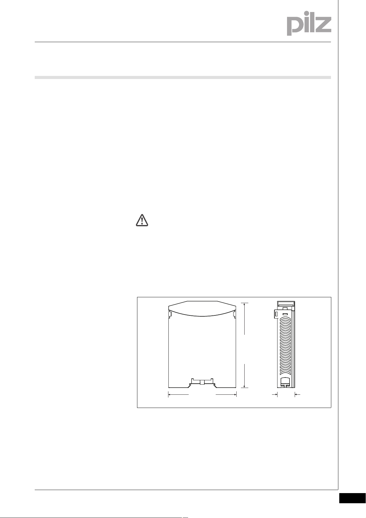
94 (3.70")
22,5
(0.88")
121 (4.76")
5.1 General installation guidelines
55000InstallationInstallation5-5.1General installation guidelines5100General installation guidelines5-Montage_multi_allgemein
Montage_EMV ESD
The control system should be installed in a control cabinet with a pro-
tection type of at least IP54. Fit the control system to a horizontal
mounting rail. The venting slots must face upward and downward.
Other mounting positions could destroy the control system.
Use the notches on the rear of the unit to attach it to a mounting rail.
Connect the control system to the mounting rail in an upright position,
so that the earthing springs on the control system are pressed on to
the mounting rail.
The ambient temperature of the PNOZmulti units in the control cabi-
net must not exceed the figure stated in the technical details, otherwise air conditioning will be required.
To comply with EMC requirements, the mounting rail must have a low
impedance connection to the control cabinet housing.
CAUTION!
Damage due to electrostatic discharge!
Electrostatic discharge can damage components. Ensure
against discharge before touching the product, e.g. by touching
an earthed, conductive surface or by wearing an earthed armband.
5.1.1 Dimensions
Dimensions5-Abmessungen
Pilz GmbH & Co. KG, Felix-Wankel-Straße 2, 73760 Ostfildern, Germany
Telephone: +49 711 3409-0, Telefax: +49 711 3409-133, E-Mail: pilz.gmbh@pilz.de
5-1
Page 18

5 Installation
5.2 Connecting the base unit and expansion modules
5.2Connecting the base unit and expansion modules5200Connecting the base unit and expansion modules5-Montage_multi_Anzahl_Module_links_1
Montage_multi_Modul_verbind_links_BA
You can install a maximum of 1 PNOZ mc3p to the left of the base unit.
Do not connect a terminator to the last expansion module on the left-
hand side.
Install the expansion module in the position in which it is configured
in the PNOZmulti Configurator.
5-2
Pilz GmbH & Co. KG, Felix-Wankel-Straße 2, 73760 Ostfildern, Germany
Telephone: +49 711 3409-0, Telefax: +49 711 3409-133, E-Mail: pilz.gmbh@pilz.de
Page 19

6 Commissioning
1
5
9
6
1: n.c.
2: n.c.
3: B (RxD/TxD-P)
4: CNTR-P
5: DGND
6: VP
7: n.c.
8: A (RxD/TxD-N)
9: n.c.
6.1 Wiring
66000CommissioningComm issioning6-6.1Wiring6100Wiring6-
6.1.1 General wiring guidelines
General wiring guidelines6-Verdrahtung_multi_Modul
The wiring is defined in the circuit diagram of the PNOZmulti Configurator.
Note:
Verdrahtung_Montageschiene mit Schutzerde verbinden
Verdrahtung_Netzteil_sichere_Trennung
Information given in the "Technical details" must be followed.
Always connect the mounting rail to the protective earth via an earth-
ing terminal. This will be used to dissipate hazardous voltages in the
case of a fault.
The power supply must meet the regulations for extra low voltages
with safe separation.
6.1.2 Connecting the supply voltage
Connecting the supply voltag e6-Verdrahtun g_multi_Feldbus_Versorgungsspannung
Connect the supply voltage to the base unit:
Terminal 24 V and A1 (+): + 24 VDC
Terminal 0 V and A2 (-): 0 V
6.1.3 PROFIBUS DP interface
PROFIBUS DP interface6-Verdrahtung
It is possible to define which outputs on the control system will communicate with PROFIBUS-DP. The connection to PROFIBUS-DP is made
via a female 9-pin D-Sub connector in accordance with the guidelines of
the PROFIBUS User Group (PNO).
n.c. = not connected
Please note the following when connecting to PROFIBUS-DP:
Only use metal plugs or metallised plastic plugs
Twisted pair, screened cable must be used to connect the interfaces
Pilz GmbH & Co. KG, Felix-Wankel-Straße 2, 73760 Ostfildern, Germany
Telephone: +49 711 3409-0, Telefax: +49 711 3409-133, E-Mail: pilz.gmbh@pilz.de
6-1
Page 20

6 Commissioning
1
2
3
4
9
8
7
6
0
5
x10
1
2
3
4
9
8
7
6
0
5
x1
6.2 Preparing for operation
6.2Preparing for operation6200Preparing for operation6-
6.2.1 Setting the station address
Setting the station address6-Verdrahtung_multi_Feldbus_Stationsadresse einstellen_Profibus
The station address of the expansion module PNOZ mc3p is set between 0 ... 99 (decimal) via two rotary switches x1 and x10.
On the upper rotary switch x10, use a small screwdriver to set the
tens digit for the address (“3” in the example).
On the lower rotary switch x1, set the ones digit for the address (“6”
in the example).
Station address 36 is set in the diagrams as an example.
6.2.2 Download modified project to the control system PNOZmulti
Download modified project to the control system PNOZmulti6-Verdrahtung_multi_Modul_Betr_geaend_Projekt_BA
As soon as an additional expansion module has been connected to the
system, the project must be amended using the PNOZmulti Configurator. Proceed as described in the operating instructions for the base unit.
NOTICE
For the commissioning and after every program change, you
must check whether the safety devices are functioning correctly.
6-2
Pilz GmbH & Co. KG, Felix-Wankel-Straße 2, 73760 Ostfildern, Germany
Telephone: +49 711 3409-0, Telefax: +49 711 3409-133, E-Mail: pilz.gmbh@pilz.de
Page 21

6 Commissioning
PROFIBUS-DP
PNOZ mc3p
FAULT
OFFLINE
x1
x10
X1
PROFIBUS-DP
Master
PROFIBUS-DP
Slave 1
PROFIBUS-DP
Slave 2
PROFIBUS-DP
Slave 3
PROFIBUS-DP
Slave n
PNOZ mc3p PROFIBUS
ONLINE
ADDRESS
6.2 Preparing for operation
6.2.3 Connection example
Connection example6-Anschlussbeisp-mc3p
Pilz GmbH & Co. KG, Felix-Wankel-Straße 2, 73760 Ostfildern, Germany
Telephone: +49 711 3409-0, Telefax: +49 711 3409-133, E-Mail: pilz.gmbh@pilz.de
6-3
Page 22

6 Commissioning
6-4
Pilz GmbH & Co. KG, Felix-Wankel-Straße 2, 73760 Ostfildern, Germany
Telephone: +49 711 3409-0, Telefax: +49 711 3409-133, E-Mail: pilz.gmbh@pilz.de
Page 23

7 Operation
7.1 Messages
77000OperationOperation7-7.1Messages71 00Messages7-Betrieb_Meldungen_allgemein_BA
Betrieb_Meldungen_Feldbus_Profibus
When the supply voltage is switched on, the PNOZmulti safety system
copies the configuration from the chip card.
The LEDs "POWER","DIAG", "FAULT", "IFAULT" and "OFAULT" light up
on the base unit.
The expansion module PNOZ mc3p is configured and started automatically. The "ONLINE" and "OFFLINE" LEDs indicate the status of the
PNOZ mc3p on PROFIBUS-DP.
If the expansion module PNOZ mc3p does not receive a configuration
from the base unit for a period of 30 s, the expansion module
PNOZ mc3p connects to PROFIBUS-DP and "ONLINE" status is displayed on PROFIBUS-DP. The error message "External Error" is sent to
the Master.
Pilz GmbH & Co. KG, Felix-Wankel-Straße 2, 73760 Ostfildern, Germany
Telephone: +49 711 3409-0, Telefax: +49 711 3409-133, E-Mail: pilz.gmbh@pilz.de
7-1
Page 24

7 Operation
7.2 Display elements
7.2Display elements72 00Display elements7-Anzeige Legende 3x
Legend:
7.2.1 Display elements for device diagnostics
Display elements for device diagnostics7-Betrieb_Anzeige_Feldbus _PROFIBUS-DP_BA
LED Meaning
POWER Supply voltage is present
Supply voltage is not present
LED on
LED flashes
LED off
ONLINE PNOZ mc3p online, data exchange is possible
Master has sent the telegram "Global Control Clear". Virtual input bits i0 ... i23 are set
to "0"; expanded input bits i24 ... i127 are frozen.
PNOZ mc3p not online
OFFLINE PNOZ mc3p offline, data exchange is not possible
PNOZ mc3p not offline
FAULT Application Watchdog Timeout
1 Hz Configuration error, length of input and/or output data during initialisation of the
PNOZ mc3p does not match the configuration
Remedy:
Ensure that the right GSD file has been used.
2 Hz Configuration error, length/contents of configuration data during initialisation of the
PNOZ mc3p does not match the configuration
Remedy:
Ensure that the right GSD file has been used.
4 Hz Error when initialising PROFIBUS-DP
No error
7-2
Pilz GmbH & Co. KG, Felix-Wankel-Straße 2, 73760 Ostfildern, Germany
Telephone: +49 711 3409-0, Telefax: +49 711 3409-133, E-Mail: pilz.gmbh@pilz.de
Page 25

8 Technical Details
8.1 Technical Details
81000Technical DetailsTechnical Details8-8. 1Technical Details1100Technical Details8-][Technische Daten_multi_Basis
Technical details
Electrical data
Module's supply voltage via base unit 5 V DC
Voltage tolerance -2 %/+2 %
Power consumption 2.5 W
Status display LED
Times
Supply interruption before de-energisation 20 ms
Fieldbus interface
Fieldbus interface PROFIBUS DP
Device type Slave
Station address 0 - 99d
Transmission rate 9.6 kBit/s - 12 MBit/s
Connection Female 9-pin D-SUB connector
Galvanic isolation yes
Test voltage 500 V AC
Environmental data
Ambient temperature 0 - 60 °C
Storage temperature -25 - 70 °C
Climatic suitability in accordance with EN 60068-2-30,
EN 60068-2-78
Condensation not permitted
EMC EN 61131-2
Vibration to EN 60068-2-6
Frequency 10 - 150 Hz
Max. acceleration 1g
Airgap creepage in accordance with EN 61131-2
Overvoltage category III
Pollution degree 2
Rated insulation voltage 30 V
Shock stress
EN 60068-2-27 15g
Mechanical data
Protection type
Mounting (e.g. cabinet) IP54
Housing IP20
Terminals IP20
DIN rail
Top hat rail 35 x 7.5 EN 50022
Recess width 27 mm
Housing material
Housing PPO UL 94 V0
Front ABS UL 94 V0
Dimensions
Height 94.0 mm
Width 22.5 mm
Depth 119.0 mm
Weight 119 g
Technische Daten_Satz No rmen
The standards current on 2011-09 apply.
93 % r. h. at 40 °C
11 ms
Pilz GmbH & Co. KG, Felix-Wankel-Straße 2, 73760 Ostfildern, Germany
Telephone: +49 711 3409-0, Telefax: +49 711 3409-133, E-Mail: pilz.gmbh@pilz.de
8-1
Page 26

8 Technical Details
8.2 Order reference
8.2Order reference8200Order reference8-Best elldaten PN OZ mc3p
Order reference
Product type Features Order no.
PNOZ mc3p Fieldbus module, PROFIBUS-DP 773 732
Bestelldaten Zubehör Abschlussstecker/Steckbrücke
Order reference: Terminator, jumper
Product type Features Order no.
PNOZmulti bus terminator Terminator 779 110
KOP-XE Jumper 774 639
8-2
Pilz GmbH & Co. KG, Felix-Wankel-Straße 2, 73760 Ostfildern, Germany
Telephone: +49 711 3409-0, Telefax: +49 711 3409-133, E-Mail: pilz.gmbh@pilz.de
Page 27

...
21010-EN-05, 2012-04 Printed in Germany
© Pilz GmbH & Co. KG, 2011
+49 711 3409-444
support@pilz.com
Pilz GmbH & Co. KG
Felix-Wankel-Straße 2
73760 Ostfildern, Germany
Telephone: +49 711 3409-0
Telefax: +49 711 3409-133
E-Mail: pilz.gmbh@pilz.de
Internet: www.pilz.com
Technical support
In many countries we are
represented by our subsidiaries
and sales partners.
Please refer to our homepage
for further details or contact our
headquarters.
InduraNET p
®
, Pilz
®
, PIT
®
, PMCprotego
®
, PMI
®
, PNOZ
®
, Primo
®
, PSEN
®
, PSS
®
, PVIS
®
, SafetyBUS p
®
, SafetyEYE
®
, SafetyNET p
®
, the spirit of safety
®
are registered and protected trademarks
of Pilz GmbH & Co. KG in some countries. We would point out that product features may vary from the details stated in this document, depending on the status at the time of publication and the scope
of the equipment. We accept no responsibility for the validity, accuracy and entirety of the text and graphics presented in this information. Please contact our Technical Support if you have any questions.
Contact address
 Loading...