

Page 1

PNOZ mc12p
Configurable Control System PNOZmulti
Operating Manual-1003016-EN-01
Page 2

Preface
This document is a translation of the original document.
All rights to this documentation are reserved by Pilz GmbH & Co. KG. Copies may be made
for internal purposes. Suggestions and comments for improving this documentation will be
gratefully received.
Pilz®, PIT®, PMI®, PNOZ®, Primo®, PSEN®, PSS®, PVIS®, SafetyBUS p®, SafetyEYE®,
SafetyNET p®, the spirit of safety® are registered and protected trademarks of Pilz GmbH
& Co. KG in some countries.
SD means Secure Digital
Page 3

Content
Section 1 Introduction 4
1.1 Validity of documentation 4
1.2 Retaining the documentation 4
1.3 Definition of symbols 4
Section 2 Overview 5
2.1 Scope of delivery 5
2.2 Unit features 5
2.3 Front view 6
Section 3 Safety 7
3.1 Intended use 7
3.2 System requirements 7
3.3 Safety regulations 7
3.3.1 Use of qualified personnel 7
3.3.2 Warranty and liability 8
3.3.3 Disposal 8
3.3.4 For your safety 8
Section 4 Function description 9
4.1 Functions 9
4.2 Input and output data 9
4.3 Block diagram 10
Section 5 Installation 11
5.1 General installation guidelines 11
5.2 Dimensions 11
5.3 Connecting the base unit and expansion modules 11
Section 6 Commissioning 12
6.1 General wiring guidelines 12
6.2 Interface assignment 12
6.3 Download modified project to the PNOZmulti safety system 13
6.4 Connection example 13
Section 7 Operation 14
7.1 Messages 14
Section 8 Technical Details 16
Section 9 Order reference 18
Operating Manual PNOZ mc12p
1003016-EN-01
3
Page 4
Introduction
1
1.1
1.2
1.3
Introduction
Validity of documentation
This documentation is valid for the product PNOZ mc12p. It is valid until new documentation is published.
This operating manual explains the function and operation, describes the installation and
provides guidelines on how to connect the product.
Retaining the documentation
This documentation is intended for instruction and should be retained for future reference.
Definition of symbols
Information that is particularly important is identified as follows:
DANGER!
This warning must be heeded! It warns of a hazardous situation that poses
an immediate threat of serious injury and death and indicates preventive
measures that can be taken.
WARNING!
This warning must be heeded! It warns of a hazardous situation that could
lead to serious injury and death and indicates preventive measures that can
be taken.
ATTENTION!
This refers to a hazard that can lead to a less serious or minor injury plus
material damage, and also provides information on preventive measures
that can be taken.
CAUTION!
This describes a situation in which the product or devices could be damaged and also provides information on preventive measures that can be taken. It also highlights areas within the text that are of particular importance.
Information
Operating Manual PNOZ mc12p
1003016-EN-01
This gives advice on applications and provides information on special features.
4
Page 5

Overview
2
2.1
2.2
Overview
Scope of delivery
} Expansion module PNOZ mc12p
} Jumper 774 639
Unit features
Using the product PNOZ mc12p:
Expansion module for connection to a base unit from the configurable control system
PNOZmulti
The product has the following features:
} Can be configured in the PNOZmulti Configurator
} Connection for Ethernet POWERLINK (Ethernet POWERLINK V 2 protocol)
} Station addresses from 1 ... 239, selected via rotary switch
} The minimum cycle time for an application of 20 Byte Output and 50 Byte Input is
350µs. The minimum cycle time is 500 µs at the maximum PDO size of 240 Byte Input
and 20 Byte Output. (The inputs and outputs in this case are viewed from the Managing
Node.)
} 24 virtual inputs and outputs on the control system PNOZmulti can be defined in the
PNOZmulti Configurator for communication with the fieldbus Ethernet POWERLINK .
The number of inputs and outputs can be extended to 128. Please note that when the
extended inputs and outputs 24 - 127 are used they have different properties (see document entitled "Communication Interfaces").
} Max. 1 PNOZ mc12p can be connected to the base unit
} Please refer to the document "PNOZmulti System Expansion" for the PNOZmulti base
units that can be connected
Operating Manual PNOZ mc12p
1003016-EN-01
5
Page 6
Overview
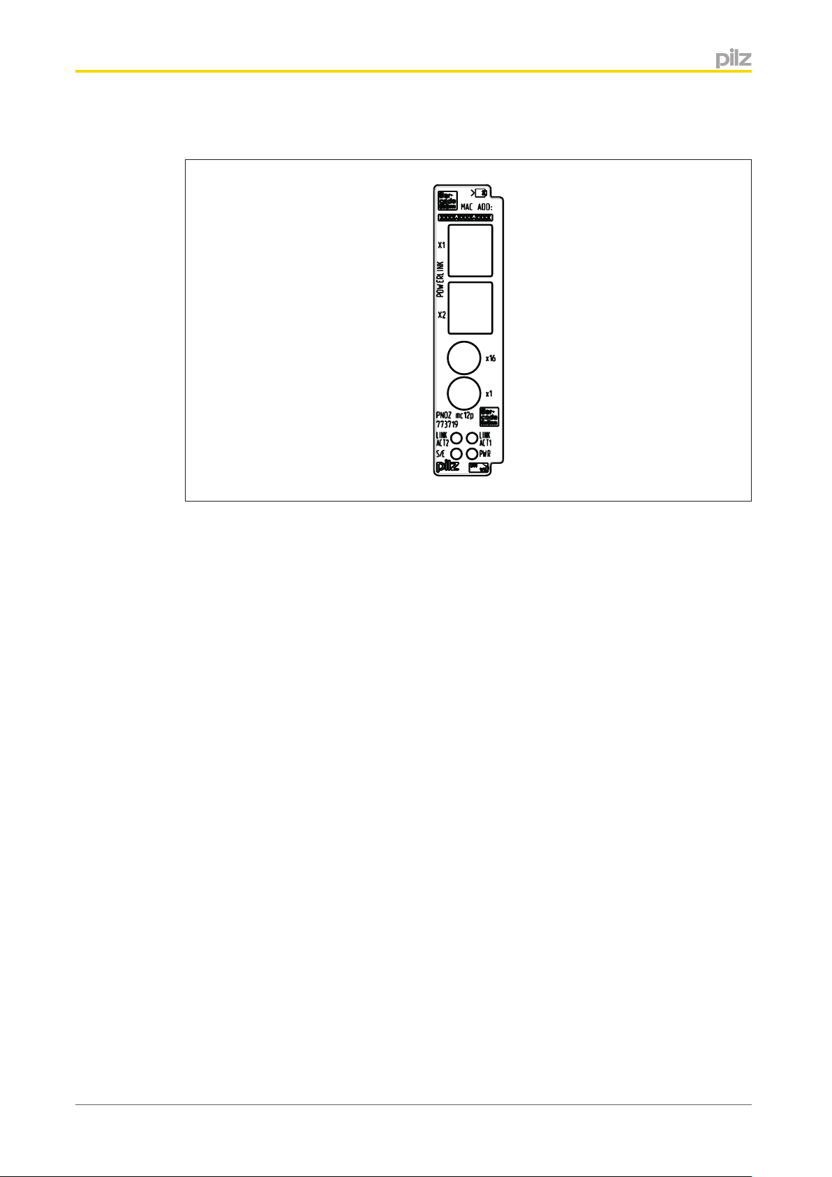
2.3
Front view
Legend:
} X1, X2 Ethernet POWERLINK interfaces
} LED:
– LINK ACT1
– LINK ACT2
– PWR
– S/E (Status/Error)
Operating Manual PNOZ mc12p
1003016-EN-01
6
Page 7

Safety
3
3.1
Safety
Intended use
The fieldbus module PNOZ mc12p is an expansion module of the configurable control system PNOZmulti. It is used for communication between the configurable control system
PNOZmulti and Ethernet POWERLINK. Ethernet POWERLINK is designed for fast data
exchange at field level. The expansion module PNOZ mc12p is a passive subscriber (Controlled Node) of Ethernet POWERLINK . The basic communication functions with Ethernet
POWERLINK conform to the System Description published by the POWERLINK User
Group (EPSG). The central controller (Managing Node) reads input information from the
slaves and writes output information to the slaves as part of each cycle. As well as the cyclical transfer of usable data, the expansion module PNOZ mc12p also has diagnostic and
commissioning functions.
The expansion module may only be connected to a base unit from the configurable control
system PNOZmulti (please refer to the document "PNOZmulti System Expansion" for details of the base units that can be connected)
The configurable control system PNOZmulti is used for the safety-related interruption of
safety circuits and is designed for use in:
} E-STOP equipment
} Safety circuits in accordance with VDE 0113 Part 1 and EN 60204-1
3.2
3.3
3.3.1
The expansion module may not be used for safety-related functions.
Intended use includes making the electrical installation EMC-compliant. The product is designed for use in an industrial environment. It is not suitable for use in a domestic environment, as this can lead to interference.
The following is deemed improper use in particular:
} Any component, technical or electrical modification to the product
} Use of the product outside the areas described in this manual
} Use of the product outside the technical details (see chapter entitled “Technical De-
tails”)
System requirements
Please refer to the "Product Modifications" document in the "Version overview" section for
details of which versions of the base unit and PNOZmulti Configurator can be used for this
product.
Safety regulations
Use of qualified personnel
The products may only be assembled, installed, programmed, commissioned, operated,
maintained and decommissioned by competent persons.
Operating Manual PNOZ mc12p
1003016-EN-01
7
Page 8

Safety
A competent person is someone who, because of their training, experience and current professional activity, has the specialist knowledge required to test, assess and operate the
work equipment, devices, systems, plant and machinery in accordance with the general
standards and guidelines for safety technology.
It is the company’s responsibility only to employ personnel who:
} Are familiar with the basic regulations concerning health and safety / accident preven-
tion
} Have read and understood the safety guidelines given in this description
} Have a good knowledge of the generic and specialist standards applicable to the spe-
cific application.
3.3.2
3.3.3
3.3.4
Warranty and liability
All claims to warranty and liability will be rendered invalid if
} The product was used contrary to the purpose for which it is intended
} Damage can be attributed to not having followed the guidelines in the manual
} Operating personnel are not suitably qualified
} Any type of modification has been made (e.g. exchanging components on the PCB
boards, soldering work etc.).
Disposal
} In safety-related applications, please comply with the mission time tM in the safety-relat-
ed characteristic data.
} When decommissioning, please comply with local regulations regarding the disposal of
electronic devices (e.g. Electrical and Electronic Equipment Act).
For your safety
The unit meets all necessary conditions for safe operation. However, you should always ensure that the following safety requirements are met:
} This operating manual only describes the basic functions of the unit. Information on the
advanced functions can be found in the online help for the PNOZmulti Configurator and
in the PNOZmulti technical catalogue. Only use these functions after you have read and
understood the documentation. All necessary documentation can be found on the
PNOZmulti Configurator CD.
} Do not open the housing or make any unauthorised modifications.
} Please make sure you shut down the supply voltage when performing maintenance
work (e.g. exchanging contactors).
Operating Manual PNOZ mc12p
1003016-EN-01
8
Page 9

Function description
4
4.1
4.2
Function description
Functions
The virtual inputs and outputs that are to be transferred via the fieldbus Ethernet POWERLINK are selected and configured in the PNOZmulti Configurator. The base unit and the
fieldbus module PNOZ mc12p are connected via a jumper. The fieldbus module is also
supplied with voltage via this jumper. After the supply voltage is switched on or the control
system PNOZmulti is reset, the fieldbus module PNOZ mc12p is configured and started automatically.
LEDs indicate the status of the fieldbus module on the fieldbus Ethernet POWERLINK .
The configuration is described in detail in the PNOZmulti Configurator's online help.
Input and output data
The data is structured as follows:
} Input range
The inputs are defined in the Managing Node and transferred to the PNOZmulti. Each
input has a number, e.g. input bit 4 of SDO 2100:02 has the number i12.
Virtual inputs
PNOZmulti Configurator
I0 … I7 I8 … I15 I16 … I23
Ethernet POWERLINK
} Output range
The outputs are defined in the PNOZmulti Configurator. Each output that is used is giv-
en a number there, e.g. o0, o5... The state of output o0 is stored in Bit 0 of SDO
2000:01.
Virtual outputs
PNOZmulti Configurator
Ethernet POWERLINK
Detailed information on data exchange is available in the document "Communication Interfaces" in the section entitled "Fieldbus modules".
The number of virtual inputs and outputs can be extended to 128 (see document "Communication Interfaces" in the section entitled "Fieldbus modules")
SDO 2100:01:
Bit 0 … 7
O0 … O7 O8 … O15 O16 … O23
SDO 2000:01:
Bit 0 … 7
SDO 2100:02:
Bit 0 … 7
SDO 2000:02:
Bit 0 … 7
SDO 2100:03:
Bit 0 … 7
SDO 2000:03:
Bit 0 … 7
Operating Manual PNOZ mc12p
1003016-EN-01
9
Page 10
Function description
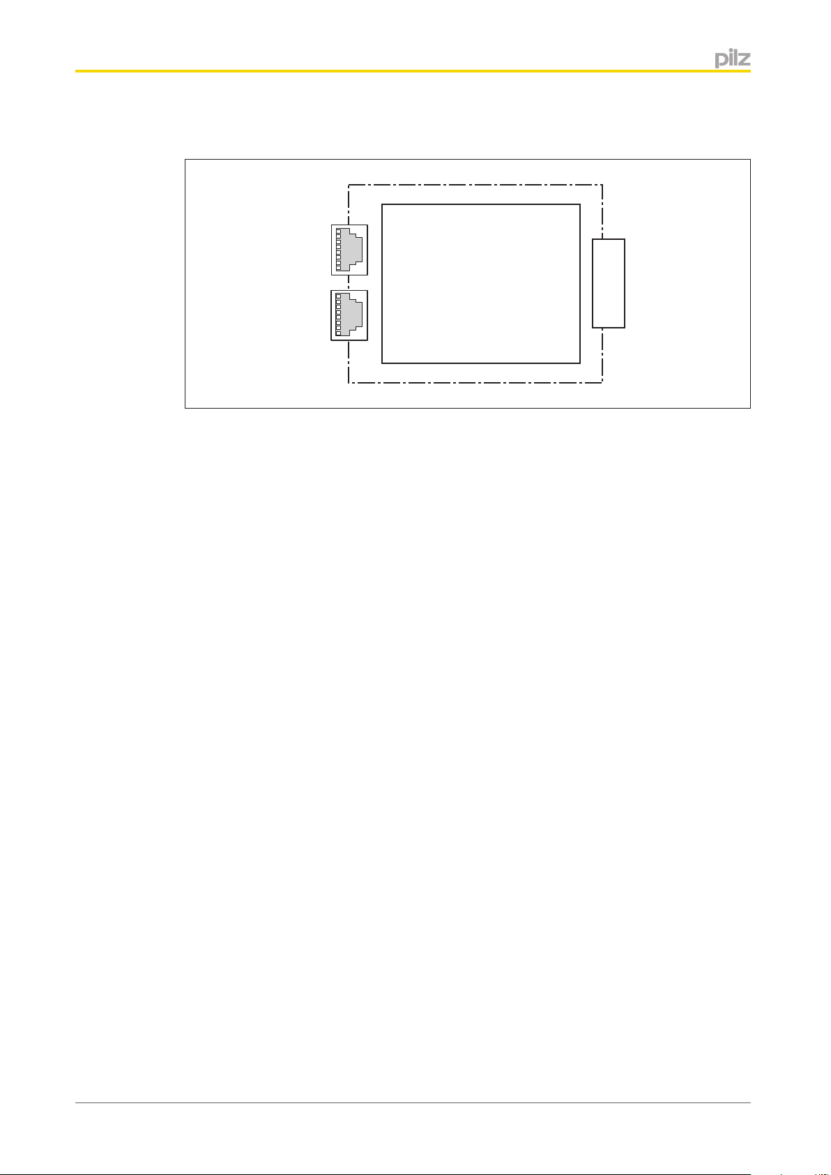
4.3
Block diagram
Base unit
Ethernet POWERLINK
Operating Manual PNOZ mc12p
1003016-EN-01
10
Page 11

Installation
5
5.1
Installation
General installation guidelines
} The control system should be installed in a control cabinet with a protection type of at
least IP54. Fit the control system to a horizontal mounting rail. The venting slots must
face upward and downward. Other mounting positions could destroy the control system.
} Use the notches on the rear of the unit to attach it to a mounting rail. Connect the con-
trol system to the mounting rail in an upright position, so that the earthing springs on the
control system are pressed on to the mounting rail.
} The ambient temperature of the PNOZmulti units in the control cabinet must not exceed
the figure stated in the technical details, otherwise air conditioning will be required.
} To comply with EMC requirements, the mounting rail must have a low impedance con-
nection to the control cabinet housing.
ATTENTION!
Damage due to electrostatic discharge!
Electrostatic discharge can damage components. Ensure against discharge
before touching the product, e.g. by touching an earthed, conductive surface
or by wearing an earthed armband.
5.2
5.3
Dimensions
Connecting the base unit and expansion modules
You can install a maximum of 1 PNOZ mc12p to the left of the base unit.
} Do not connect a terminator to the last expansion module on the left-hand side.
} Install the expansion module in the position in which it is configured in the PNOZmulti
Configurator.
Operating Manual PNOZ mc12p
1003016-EN-01
11
Page 12
Commissioning
6
6.1
Commissioning
General wiring guidelines
The wiring is defined in the circuit diagram of the PNOZmulti Configurator. It is possible to
define which inputs and outputs on the safety system will communicate with the Ethernet
POWERLINK.
Please note:
} Information given in the "Technical details" must be followed.
} Use copper wire that can withstand 75 °C.
Please note the following when connecting to Ethernet POWERLINK :
} The following minimum requirements of the connection cable and connector must be
met:
– Only use standard industrial Ethernet cable and connectors.
– Only use double-shielded twisted pair cable and shielded RJ45 connectors (indus-
trial connectors).
– 100BaseTX cable in accordance with the Ethernet standard (min. Category 5)
} Measures to protect against interference:
Ensure the requirements for the industrial use of Ethernet POWERLINK are met, as
stated in the Installation Manual published by the User Group.
6.2
ATTENTION!
Only connect and disconnect the expansion module when the supply voltage is switched off.
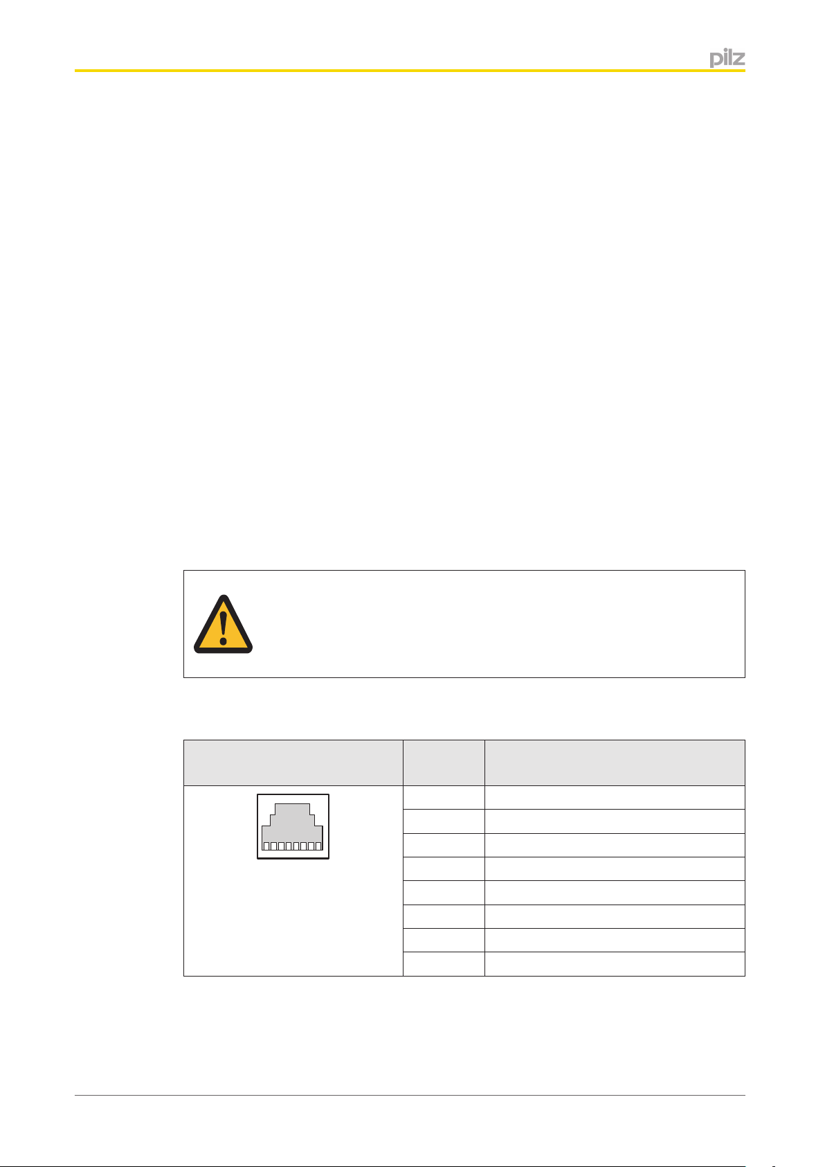
Interface assignment
RJ45 socket
8-pin PIN Standard
1 TD+ (Transmit+)
2 TD- (Transmit-)
3 RD+ (Receive+)
n.c.: Not connected
4 n.c.
5 n.c.
6 RD- (Receive-)
7 n.c.
8 n.c.
Operating Manual PNOZ mc12p
1003016-EN-01
12
Page 13
Commissioning
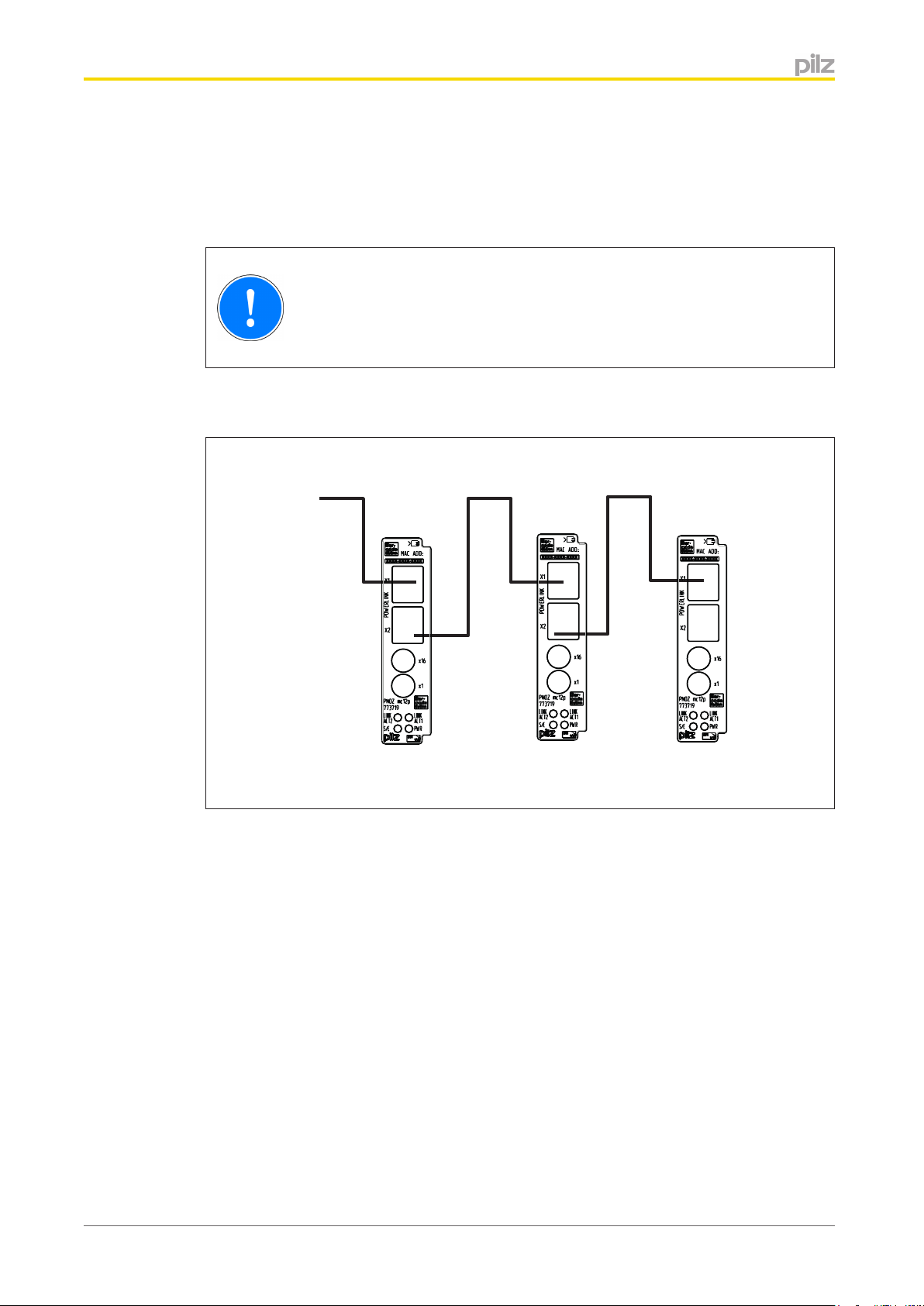
Ethernet POWERLINK
Managing Node
Controlled Node 1
Controlled Node 2
Ethernet POWERLINK
Controlled Node 3
6.3
6.4
Download modified project to the PNOZmulti safety system
As soon as an additional expansion module has been connected to the system, the project
must be amended using the PNOZmulti Configurator. Proceed as described in the operating instructions for the base unit.
CAUTION!
For the commissioning and after every program change, you must check
whether the safety devices are functioning correctly.
Connection example
Ethernet POWERLINK
Ethernet POWERLINK
Operating Manual PNOZ mc12p
1003016-EN-01
13
Page 14

Operation
7
7.1
LED Meaning
Operation
When the supply voltage is switched on, the PNOZmulti safety system copies the configuration from the chip card.
The LEDs "POWER","DIAG", "FAULT", "IFAULT" and "OFAULT" light up on the base unit.
The expansion module PNOZ mc12p is configured and started automatically.
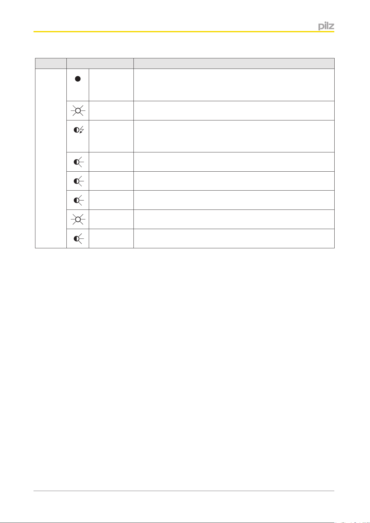
Messages
Legend:
LED on
LED flashes
LED flashes quickly 0.5 s on, 3 s off
LED off
PWR
LINK
ACT1
LINK
ACT2
Supply voltage is present
Supply voltage is not present
Green Bus connection available at X1
Green Data traffic present at X1
Bus connection is not available at X1
Green Bus connection available at X2
Green Data traffic present at X2
Bus connection not available at X2
Operating Manual PNOZ mc12p
1003016-EN-01
14
Page 15
Operation
LED Meaning
S/E
No supply at the bus controller or the bus controller is in a NOT_ACTIVE state.
If communication with Ethernet POWERLINK is not detected within 5 s,
the bus controller switches to a BASIC_Ethernet state.
Red Bus controller in a fault condition (e.g. loss of Ethernet Frames, accu-
mulation of collisions on the network etc.)
Green The bus controller has not detected any communication with Ethernet
POWERLINK. It is possible to communicate with the bus controller directly via UDP. If communication with Ethernet POWERLINK is detected, the bus switches to a PRE_OPERATIONAL_1 state.
Green: 1x The bus controller is in a PRE_OPERATIONAL_1 state.
Green: 2 x
The bus controller is in a PRE_OPERATIONAL_2 state.
short
Green: 3 x
The bus controller is in a READY_TO_OPERATE state.
short
Green The bus controller is in an OPERATIONAL state.
Green The bus controller is in a STOPPED state.
Operating Manual PNOZ mc12p
1003016-EN-01
15
Page 16

Technical Details
8
General 773719
Approvals CCC, CE, GOST
Electrical data 773719
Supply voltage
For Module supply
Internal Via base unit
Voltage 5 V
Type DC
Voltage tolerance -2 %/+2 %
Power consumption 1,6 W
Status indicator LED
Fieldbus interface 773719
Fieldbus interface Ethernet POWERLINK V2
Unit type Controlled Node
Transmission rates 100 MBit/s
Connection RJ45
Galvanic isolation Yes
Times 773719
Supply interruption before de-energisation 20 ms
Environmental data 773719
Ambient temperature
In accordance with the standard EN 60068-2-14
Temperature range 0 - 60 °C
Storage temperature
In accordance with the standard EN 60068-2-1/-2
Temperature range -25 - 70 °C
Climatic suitability
In accordance with the standard EN 60068-2-30
Humidity 93 % r. h. at 40 °C
Condensation Not permitted
EMC EN 61131-2
Vibration
In accordance with the standard EN 60068-2-6
Frequency 10,0 - 150,0 Hz
Max. acceleration 1g
Shock stress
In accordance with the standard EN 60068-2-27
Acceleration 15g
Duration 11 ms
Max. operating height above sea level 2000 m
Airgap creepage
In accordance with the standard EN 61131-2
Overvoltage category III
Pollution degree 2
Technical Details
Operating Manual PNOZ mc12p
1003016-EN-01
16
Page 17

Technical Details
Environmental data 773719
Rated insulation voltage 25 V
Protection type
In accordance with the standard EN 60529
Mounting (e.g. cabinet) IP54
Housing IP20
Terminals IP20
Potential isolation 773719
Potential isolation between Fieldbus and module voltage
Type of potential isolation Functional insulation
Rated surge voltage 500 V
Mechanical data 773719
Mounting position Horizontal on top hat rail
DIN rail
Top hat rail 35 x 7,5 EN 50022
Recess width 27 mm
Material
Bottom PPO UL 94 V0
Front ABS UL 94 V0
Dimensions
Height 94,0 mm
Width 22,5 mm
Depth 114,0 mm
Weight 115 g
The standards current on 2012-06 apply.
Operating Manual PNOZ mc12p
1003016-EN-01
17
Page 18

Order reference
9
Order reference
Product type Features Order no.
PNOZ mc12p Fieldbus module, Ethernet POWERLINK 773 719
Order reference: Terminator, jumper
Product type Features Order no.
PNOZmulti bus terminator Terminator 779 110
KOP-XE Jumper 774 639
Order reference
Operating Manual PNOZ mc12p
1003016-EN-01
18
Page 19

© Pilz GmbH & Co. KG, 2011
of the equipment. We accept no responsibility for the validity, accuracy and entirety of the text and graphics presented in this information. Please contact our Technical Support if you have any questions.
Back cover
Sachnummer Printed in Germany
1003016-EN-01, 2013-05 Printed in Germany
© Pilz GmbH & Co. KG, 2011
...
In many countries we are
represented by our subsidiaries
and sales partners.
Please refer to our homepage
for further details or contact our
headquarters.
Technical support
+49 711 3409-444
support@pilz.com
are registered and protected trademarks
®
, the spirit of safety
®
, SafetyNET p
®
, SafetyEYE
®
, SafetyBUS p
®
, PVIS
®
, PSS
®
, PSEN
®
, Primo
®
, PNOZ
®
, PMI
®
Pilz GmbH & Co. KG
Felix-Wankel-Straße 2
73760 Ostfildern, Germany
Telephone: +49 711 3409-0
Telefax: +49 711 3409-133
E-Mail: pilz.gmbh@pilz.de
Internet: www.pilz.com
, PMCprotego
®
, PIT
®
, Pilz
®
of Pilz GmbH & Co. KG in some countries. We would point out that product features may vary from the details stated in this document, depending on the status at the time of publication and the scope
InduraNET p
 Loading...