

Page 1

WORKSHOP MANUAL
633120
Liberty 125 - 200 4tempi
Page 2

WORKSHOP
MANUAL
Liberty 125 - 200 4tempi
The descriptions and illustrations given in this publication are not binding. While the basic specifications
as described and illustrated in this booklet remain unchanged, PIAGGIO-GILERA reserves the right, at
any time and without being required to update this publication beforehand, to make any changes to
components, parts or accessories, which it considers necessary to improve the product or which are
required for manufacturing or construction reasons.
Not all versions shown in this publication are available in all countries. The availability of single models
should be checked at the official Piaggio sales network.
"© Copyright 2008 - PIAGGIO & C. S.p.A. Pontedera. All rights reserved. Reproduction of this publication
in whole or in part is prohibited."
PIAGGIO & C. S.p.A. - After-Sales
V.le Rinaldo Piaggio, 23 - 56025 PONTEDERA (Pi)
Page 3

WORKSHOP MANUAL
Liberty 125 - 200 4tempi
This workshop manual has been drawn up by Piaggio & C. Spa to be used by the workshops of PiaggioGilera dealers. This manual is addressed to Piaggio service mechanics who are supposed to have a
basic knowledge of mechanics principles and of vehicle fixing techniques and procedures. Any important
changes made to the vehicles or to specific fixing operations will be promptly reported by updates to this
manual. Nevertheless, no fixing work can be satisfactory if the necessary equipment and tools are
unavailable. It is therefore advisable to read the sections of this manual relating to specific tools, along
with the specific tool catalogue.
N.B. Provides key information to make the procedure easier to understand and carry out.
CAUTION Refers to specific procedures to carry out for preventing damages to the vehicle.
WARNING Refers to specific procedures to carry out to prevent injuries to the repairer.
Personal safety Failure to completely observe these instructions will result in serious risk of personal
injury.
Safeguarding the environment Sections marked with this symbol indicate the correct use of the vehicle
to prevent damaging the environment.
Vehicle intactness The incomplete or non-observance of these regulations leads to the risk of serious
damage to the vehicle and sometimes even the invalidity of the guarantee.
Page 4

Page 5

INDEX OF TOPICS
CHARACTERISTICS CHAR
TOOLING TOOL
MAINTENANCE MAIN
TROUBLESHOOTING TROUBL
ELECTRICAL SYSTEM ELE SYS
ENGINE FROM VEHICLE ENG VE
ENGINE ENG
SUSPENSIONS SUSP
BRAKING SYSTEM BRAK SYS
CHASSIS CHAS
PRE-DELIVERY PRE DE
TIME TIME
Page 6

INDEX OF TOPICS
CHARACTERISTICS CHAR
Page 7

Rules
This section describes general safety rules for any maintenance operations performed on the vehicle.
Safety rules
- If work can only be done on the vehicle with the engine running, make sure that the premises are wellventilated, using special extractors if necessary; never let the engine run in an enclosed area. Exhaust
fumes are toxic.
- The battery electrolyte contains sulphuric acid. Protect your eyes, clothes and skin. Sulphuric acid is
highly corrosive; in the event of contact with your eyes or skin, rinse thoroughly with abundant water
and seek immediate medical attention.
- The battery produces hydrogen, a gas that can be highly explosive. Do not smoke and avoid sparks
or flames near the battery, especially when charging it.
- Fuel is highly flammable and it can be explosive given some conditions. Do not smoke in the working
area, and avoid open flames or sparks.
- Clean the brake pads in a well-ventilated area, directing the jet of compressed air in such a way that
you do not breathe in the dust produced by the wear of the friction material. Even though the latter
contains no asbestos, inhaling dust is harmful.
Maintenance rules
- Use original PIAGGIO spare parts and lubricants recommended by the Manufacturer. Non-original or
non-conforming spares may damage the vehicle.
- Use only the appropriate tools designed for this vehicle.
- Always use new gaskets, sealing rings and split pins upon refitting.
- After removal, clean the components using non-flammable or low flash-point solvents. Lubricate all
the work surfaces, except tapered couplings, before refitting these parts.
- After refitting, make sure that all the components have been installed correctly and work properly.
- For removal, overhaul and refit operations use only tools with metric measures. Metric bolts, nuts and
screws are not interchangeable with coupling members with English measurement. Using unsuitable
coupling members and tools may damage the vehicle.
- When carrying out maintenance operations on the vehicle that involve the electrical system, make
sure the electric connections have been made properly, particularly the ground and battery connections.
Liberty 125 - 200 4tempi Characteristics
CHAR - 7
Page 8

Vehicle identification
VEHICLE IDENTIFICATION (125)
Specification Desc./Quantity
Chassis prefix (125) ZAPM38100 ÷ 1001
Engine prefix (125) M381M ÷ 1001
VEHICLE IDENTIFICATION (200)
Specification Desc./Quantity
Chassis prefix (200) ZAPM38400 ÷ 1001
Engine prefix(200) M384M ÷ 1001
Dimensions and mass
WEIGHT AND DIMENSIONS
Specification
Desc./Quantity
Dry weight 99 kg
Width 735 mm
Length 1935 mm
Wheelbase 1335 mm
Saddle height 775 mm
Characteristics Liberty 125 - 200 4tempi
CHAR - 8
Page 9

Engine
ENGINE
Specification
Desc./Quantity
Engine Single-cylinder, 4-stroke Piaggio LEADER
Timing system Single overhead camshaft (SOHC) with 2 valves
Valve clearance intake 0.10
outlet 0.15
Bore x stroke (125) 57 x 48.6 mm
Bore x stroke (200) 72 x 48.6 mm
Cubic capacity (125) 124 cm³
Cubic capacity (200) 197 cm³
Compression ratio (125) 10.6 : 1
Compression ratio (200) 9,5:1
Carburettor KEIHIN CVEK26
Engine idle speed approx. 1.600 ÷ 1.800 rpm
Start-up Electric
Maximum power to crankshaft (125) 10.5 CV at 8000 rpm
Maximum power to crankshaft (200) 12.5 CV at 6500 rpm
Cooling Forced air circulation.
Liberty 125 - 200 4tempi Characteristics
CHAR - 9
Page 10

Transmission
TRANSMISSION
Specification Desc./Quantity
Transmission With automatic expandable pulley variator with torque server,
V belt, automatic clutch, gear reduction unit and transmission
housing with forced air circulation cooling.
Capacities
CAPACITIES
Specification Desc./Quantity
Engine oil 61 in³ (1,000 cm³)
Rear hub oil ~ 200 cm³
Fuel tank capacity (125) ~ 6 litres (of which 1.5 litres is reserve)
Fuel tank (200 cc.) ~ 9 litres (including 1,5 litre reserve)
Electrical system
ELECTRICAL COMPONENTS
Specification
Desc./Quantity
Start-up Electric
Spark plug (125) Champion RG6YC- NGK CR7EB
Spark plug Champion RG6YC
Frame and suspensions
FRAME AND SUSPENSIONS
Specification
Desc./Quantity
Chassis Steel tube chassis
Front suspension Ø 32 Hydraulic telescopic fork - travel: 76 mm
Rear suspension Hydraulic single shock absorber and spring adjustable to 4 po-
sitions at preloading; travel: 85.5 mm.
Brakes
BRAKES
Specification
Desc./Quantity
Front brake Ø 220 mm disc with calliper with counteracting pistons.
Rear brake Drum brake, Ø 140 mm
Wheels and tyres
WHEELS AND TYRES
Specification
Desc./Quantity
Front wheel rim Die-cast aluminium alloy, 2.15 x16"
Rear wheel rim Die-cast aluminium alloy, 2.75 x14"
Front tyre (125) Tubeless 90/80 - 16
Rear tyre (125) Tubeless 110/80-14"
Front tyre (200) Tubeless 100/80-16"
Rear tyre (200) Tubeless 120/70 - 14"
Characteristics Liberty 125 - 200 4tempi
CHAR - 10
Page 11

Specification Desc./Quantity
Front tyre pressure 2 bar
Rear tyre pressure 2.2 bar
Rear tyre pressure (rider and luggage) 2.5 bar
Secondary air
In order to reduce polluting emissions, the vehicle
is furnished with a catalytic converter in the muffler.
To favour the catalytic process, an extra amount
of oxygen is added via a secondary air system
(SAS).
This system allows more oxygen to be added to
the unburned gases before they reach the converter, thus improving the action of the catalytic
converter.
The air enters the exhaust duct from the head, and
is purified by a black filter.
The system is fitted with a control valve that disables operation while decelerating to avoid unwanted noise.
To ensure the best functioning of the SAS system,
every 12,000 km the scooter should be taken to an
Authorised Piaggio Service Centre to have the
filter cleaned (Scheduled maintenance operations
section).
The filter sponge should be cleaned with water and
mild soap, then it should be dried with a cloth and
slight blows of compressed air.
CAUTION
CONTACT AN AUTHORISED PIAGGIO SERVICE CENTRE
TO CARRY OUT THESE OPERATIONS.
Carburettor
125cc Version
Liberty 125 - 200 4tempi Characteristics
CHAR - 11
Page 12

Kehin
CARBURETTOR SETTING
Specification Desc./Quantity
Type CVEK26
Throttle valve diameter Ø 26.5
Diffuser diameter Ø 26.4
Setting stamping 262A
Maximum jet 82
Maximum air jet (on the body) 85
Tapered pin stamping NELA
Throttle valve spring 130 ÷ 180 gr.
Minimum jet 35
Idle air jet (on the body) 150
Idle mixture adjustment screw initial opening 1 ¾
Starter jet 42
Starter air jet (on the body) Ø 1.5
Starter pin travel 10 mm (at 24°)
Starter resistance 20 Ohm (at 24°)
200cc Version
Kehin
CARBURETTOR SETTING
Specification
Desc./Quantity
Type CVEK26
Throttle valve diameter Ø 26.5
Diffuser diameter Ø 26.4
Setting stamping 265A
Maximum jet 82
Maximum air jet (on the body) 85
Tapered pin stamping NELA
Throttle valve spring 130 ÷ 180 gr.
Minimum jet 35
Idle air jet (on the body) 150
Idle mixture adjustment screw initial opening 1 ¾
Starter jet 42
Starter air jet (on the body) Ø 1.5
Starter pin travel 10 mm (at 24°)
Starter resistance 20 Ohm (at 24°)
Tightening Torques
MOTORE
Name
Torque in Nm
Ignition spark plug 10 ÷ 15 Nm
Head cover screws 8 ÷ 10
Head-cylinder stud bolt nuts 6 ÷ 7 + 90° + 90° *
Screws fixing head and cylinder to crankcase 8 ÷ 10
Chain tensioner pad screw 5 ÷ 7 Nm
Timing chain tensioner screws 8 ÷ 10 Nm
Timing chain tensioner central screw 5 - 6
Camshaft pulley screw 12 ÷ 14
Rocking lever axle and camshaft bearing screw 3 ÷ 4 Nm
Valve clearance adjustment lock nuts 7 ÷ 9 Nm
Engine oil pre-filter cover: 25 ÷ 28 Nm
Engine oil drainage cap 25 ÷ 28
Characteristics Liberty 125 - 200 4tempi
CHAR - 12
Page 13

Name Torque in Nm
Alternator flywheel nut 40 ÷ 44 Nm
Stator screws 3 ÷ 4
Pick-up screws 3 ÷ 4
Oil pump bulkhead screw 4 ÷ 5
Timing chain/oil pump compartment cover screws 4 ÷ 5 Nm
Oil decantation labyrinth sheet screws 7 ÷ 8
Oil pump crown screw 8 ÷ 10
Screws fixing oil pump to crankcase 5 ÷ 6
Oil pump coupling screws 7 ÷ 9 Nm
Oil sump screws 8 ÷ 10 Nm
Inlet manifold screw 7 ÷ 9
Carburettor/manifold clamp screw 1.2 ÷ 1.5 Nm
Screws fixing cables to starter motor 1.5 ÷ 2.5
Starter motor screws 11 ÷ 13
Transmission cover screws 11 ÷ 13 Nm
Crankcase cooling cover screw 2 ÷ 2.5
Nut locking clutch unit on pulley 55 ÷ 60 Nm
Crankshaft pulley nut 18 to 20 + 90° Nm
Driven pulley shaft nut 40 ÷ 44 Nm
Hub oil drainage screw 3 ÷ 5 Nm
Rear hub cap screws 24 ÷ 26 Nm
Wheel axle nut 115 ÷ 125
Crankcase half union screw 8 ÷ 10
Per assicurare una corretta coppia di bloccaggio lubrificare i dadi prima del montaggio.
* Montando dei nuovi prigionieri, l'operazione di serraggio dei dadi comprende l'effettuazione di 3 rotazioni di 90° dopo il primo
bloccaggio a 6÷7 Nm, pertanto: 6÷7 Nm + 90° + 90° + 90° a passaggi incrociati.
STEERING ASSEMBLY
Name
Torque in Nm
Upper steering ring nut 35 ÷ 40
Steering lower ring nut 12 ÷ 14
handlebar fixing screw 45 ÷ 55
FRAME ASSEMBLY
Name
Torque in Nm
Engine-swinging arm bolt 33 ÷ 41
Frame-swinging arm bolt 64 - 72
Shock absorber - chassis nut 20 ÷ 25
Shock absorber/engine pin 33 - 41 N.m
Rear wheel axle 104 ÷ 126
Stand bolt 20 ÷ 25
Front mudguard fixing screw 4 ÷ 6
FRONT SUSPENSION
Name
Torque in Nm
Fork bottom screw 20 ÷ 25
Front wheel axle 45 ÷ 50
Odometer drive screw 6 ÷ 7
FRONT BRAKE
Name
Torque in Nm
Brake fluid pump-hose fitting 20 ÷ 25
Brake fluid pipe-calliper fitting 20 ÷ 22
Calliper tightening screw 20 ÷ 25
Disc tightening screw (Apply LOCTITE 243 medium-strength
threadlocker)
8 ÷ 12 Nm
Oil bleeding valve 8 ÷ 12
Overhaul data
Liberty 125 - 200 4tempi Characteristics
CHAR - 13
Page 14

Assembly clearances
Cylinder - piston assy.
COUPLING BETWEEN PISTON AND ALUMINIUM CYLINDER WITH CAST IRON LINER
(125)
Name Initials Cylinder Piston Play on fitting
Coupling A 56.980 ÷ 56.987 56.933 ÷ 56.940 0.040 - 0.054
Coupling B 56.987 ÷ 56.994 56.940 ÷ 56.947 0.040 - 0.054
Coupling C 56.994 ÷ 57.001 56.947 ÷ 56.954 0.040 - 0.054
Coupling D 57.001 ÷ 57.008 56.954 ÷ 56.961 0.040 - 0.054
Coupling 1st increase A1 57.180 ÷ 57.187 57.133 ÷ 57.140 0.040 - 0.054
Coupling 1st increase B1 57.187 ÷ 57.194 57.140 ÷ 57.147 0.040 - 0.054
Coupling 1st increase C1 57.194 ÷ 57.201 57.147 ÷ 57.154 0.040 - 0.054
Coupling 1st increase D1 57.201 ÷ 57.208 57.154 ÷ 57.161 0.040 - 0.054
Coupling 2nd increase A2 57.380 ÷ 57.387 57.333 ÷ 57.340 0.040 - 0.054
Coupling 2nd increase B2 57.387 ÷ 57.394 57.340 ÷ 57.347 0.040 - 0.054
Coupling 2nd increase C2 57.394 ÷ 57.401 57.347 ÷ 57.354 0.040 - 0.054
Coupling 2nd increase D2 57.401 ÷ 57.408 57.354 ÷ 57.361 0.040 - 0.054
Coupling 3rd oversize A3 57.580 ÷ 57.587 57.533 ÷ 57.540 0.040 - 0.054
Coupling 3rd oversize B3 57.587 ÷ 57.594 57.540 ÷ 57.547 0.040 - 0.054
Coupling 3rd oversize C3 57.594 ÷ 57.601 57.547 ÷ 57.554 0.040 - 0.054
Coupling 3rd oversize D3 57.601 ÷ 57.608 57.554 ÷ 57.561 0.040 - 0.054
PISTON TO CAST IRON CYLINDER COUPLING (125)
Name
Initials Cylinder Piston Play on fitting
Coupling M 56.997 ÷ 57.004 56.944 ÷ 56.951 0.046 ÷ 0.060
Coupling N 57.004 ÷ 57.011 56.951 ÷ 56.958 0.046 ÷ 0.060
Coupling O 57.011 ÷ 57.018 56.958 ÷ 56.965 0.046 ÷ 0.060
Coupling P 57.018 ÷ 57.025 56.965 ÷ 56.972 0.046 ÷ 0.060
Coupling 1st oversize M1 57.197 ÷ 57.204 57.144 ÷ 57.151 0.046 ÷ 0.060
Coupling 1st oversize N1 57.204 ÷ 57.211 57.151 ÷ 57.158 0.046 ÷ 0.060
Coupling 1st oversize O1 57.211 ÷ 57.218 57.158 ÷ 57.165 0.046 ÷ 0.060
Coupling 1st oversize P1 57.218 ÷ 57.225 57.165 ÷ 57.172 0.046 ÷ 0.060
Coupling 2nd oversize M2 57.397 ÷ 57.404 57.344 ÷ 57.351 0.046 ÷ 0.060
Coupling 2nd oversize N2 57.404 ÷ 57.411 57.351 ÷ 57.358 0.046 ÷ 0.060
Coupling 2nd oversize O2 57.411 ÷ 57.418 57.358 ÷ 57.365 0.046 ÷ 0.060
Coupling 2nd oversize P2 57.418 ÷ 57.425 57.365 ÷ 57.372 0.046 ÷ 0.060
Coupling 3rd oversize M3 57.597 ÷ 57.604 57.544 ÷ 57.551 0.046 ÷ 0.060
Coupling 3rd oversize N3 57.604 ÷ 57.611 57.551 ÷ 57.558 0.046 ÷ 0.060
Coupling 3rd oversize O3 57.611 ÷ 57.618 57.558 ÷ 57.565 0.046 ÷ 0.060
Coupling 3rd oversize P3 57.618 ÷ 57.625 57.565 ÷ 57.572 0.046 ÷ 0.060
COUPLING BETWEEN PISTON AND CYLINDER (200)
Name
Initials Cylinder Piston Play on fitting
[p] A 71.990 ÷ 71.997 71.953 ÷ 71.960 0.030 - 0.044
[p] B 71.997 ÷ 72.004 71.960 ÷ 71.967 0.030 - 0.044
[p] C 72.004 ÷ 72.011 71.967 ÷ 71.974 0.030 - 0.044
[p] D 72.011 ÷ 72.018 71.974 ÷ 71.981 0.030 - 0.044
Piston rings
SEALING RINGS (125)
Name
Description Dimensions Initials Quantity
Compression ring 57 x 1 A 0.15 ÷ 0.30
Oil scraper ring 57x1 A 0.10 ÷ 0.30
Oil scraper ring 57x2.5 A 0.10 ÷ 0.35
Compression ring 1st
oversize
57.2 x 1 A 0.15 ÷ 0.30
Characteristics Liberty 125 - 200 4tempi
CHAR - 14
Page 15

Name Description Dimensions Initials Quantity
Oil scraper ring 1st
oversize
57.2x1 A 0.10 ÷ 0.30
Oil scraper ring 1st
oversize
57.2x2.5 A 0.10 ÷ 0.35
Compression ring 2nd
oversize
57.4x1 A 0.15 ÷ 0.30
Oil scraper ring 2nd
oversize
57.4x1 A 0.10 ÷ 0.30
Oil scraper ring 2nd
oversize
57.4x2.5 A 0.10 ÷ 0.35
Compression ring 3rd
oversize
57.6x1 A 0.15 ÷ 0.30
Oil scraper ring 3rd
oversize
57.6x1 A 0.10 ÷ 0.30
Oil scraper ring 3rd
oversize
57.6x2.5 A 0.10 ÷ 0.35
Maximum clearance after use: 1 mm
SEALING RINGS (200)
Name Description Dimensions Initials Quantity
Compression ring 72x1.5 A 0.15 ÷ 0.30
Oil scraper ring 72x1 A 0.20 ÷ 0.40
Oil scraper ring 72x2.5 A 0.20 ÷ 0.40
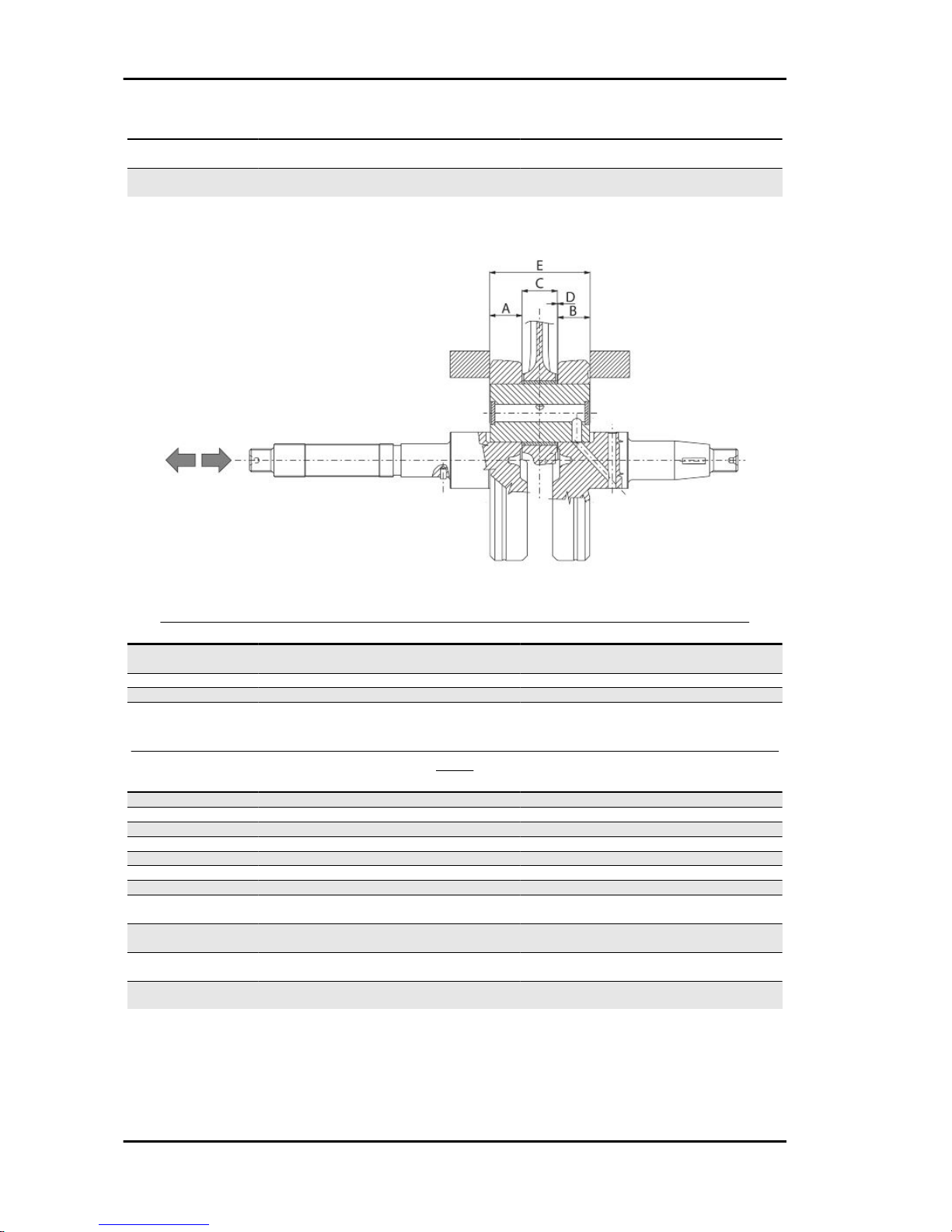
Crankcase - crankshaft - connecting rod
AXIAL CLEARANCE BETWEEN CRANKSHAFT AND CONNECTING ROD (125)
Name
Description Dimensions Initials Quantity
Half-shaft, transmission
side
16,6 +0-0,05 A D = 0.20 ÷ 0.50
Flywheel-side half shaft 16,6 +0-0,05 B D = 0.20 ÷ 0.50
Connecting rod with PP 18 -0.10 -0.15 C 0.20 ÷ 0.50
Crank pin width 51.400 E
AXIAL CLEARANCE BETWEEN CRANKSHAFT AND CRANKSHAFT HALF-BEARINGS
(125)
Name
Description Dimensions Initials Quantity
Crankshaft Category 1 28.998 ÷ 29.004
Crankshaft Class 2 29.004 ÷ 29.010
Crankcase Category 1 32.953 ÷ 32.959
Crankcase Category 2 32.959 ÷ 32.965
Crankshaft half-bearing Category B - blue 1.973 ÷ 1.976
Crankshaft half-bearing Type C - yellow 1.976 ÷ 1.979
Crankshaft half-bearing Category E - green 1.979 ÷ 1.982
Crankshaft category 1 -
Crankcase category 1
E - E
Crankshaft category 1 -
Crankcase category 2
C - C
Liberty 125 - 200 4tempi Characteristics
CHAR - 15
Page 16
Name Description Dimensions Initials Quantity
Crankshaft category 2 -
Crankcase category 1
C - C
Crankshaft category 2 -
Crankcase category 2
B - B
Crankshaft/crankcase axial clearance: 0.15 ÷ 0.40
AXIAL CLEARANCE BETWEEN CRANKSHAFT AND CONNECTING ROD (200)
Name
Description Dimensions Initials Quantity
Half-shaft, transmission
side
16,6 +0-0,05 A D = 0.20 ÷ 0.50
Flywheel-side half shaft 16,6 +0-0,05 B D = 0.20 ÷ 0.50
Connecting rod with PP 18 -0.10 -0.15 C 0.20 ÷ 0.50
Crank pin width E 51.4 +0.050
AXIAL CLEARANCE BETWEEN CRANKSHAFT AND CRANKSHAFT HALF-BEARINGS
(200)
Name
Description Dimensions Initials Quantity
Crankshaft Category 1 28.998 ÷ 29.004
Crankshaft Class 2 29.004 ÷ 29.010
Crankcase Category 1 32.959 ÷ 32.965
Crankcase Class 2 32.953 ÷ 32.959
Crankshaft half-bearing Category B - blue 1.973 ÷ 1.976
Crankshaft half-bearing Type C - yellow 1.976 ÷ 1.979
Crankshaft half-bearing Category E - green 1.979 ÷ 1.982
Crankshaft category 1 -
Crankcase category 1
E - E
Crankshaft category 1 -
Crankcase category 2
C - C
Crankshaft category 2 -
Crankcase category 1
C - C
Crankshaft category 2 -
Crankcase category 2
B - B
Crankshaft/crankcase axial clearance: 0.15 ÷ 0.43
Characteristics Liberty 125 - 200 4tempi
CHAR - 16
Page 17
Products
TABLE OF RECOMMENDED PRODUCTS
Product Description Specifications
AGIP ROTRA 80W-90 rear hub oil SAE 80W/90 Oil that exceeds the re-
quirements of API GL3 specifications
AGIP CITY HI TEC 4T Oil to lubricate flexible transmissions
(brakes, throttle control and odometer)
Oil for 4-stroke engines
AGIP FILTER OIL Oil for air filter sponge Mineral oil with specific additives for in-
creased adhesiveness
AGIP GP 330 Grease (brake control levers, throttle
grip)
Calcium complex soap-based grease
with NLGI 2; ISO-L-XBCIB2
AGIP CITY HI TEC 4T Engine oil SAE 5W-40, API SL, ACEA A3, JASO MA
Synthetic oil
AGIP GREASE MU3 Grease for odometer transmission gear
case
Soap-based lithium grease with NLGI 3;
ISO-L-XBCHA3, DIN K3K-20
Liberty 125 - 200 4tempi Characteristics
CHAR - 17
Page 18

INDEX OF TOPICS
TOOLING TOOL
Page 19

TOOLS
Stores code Description
001330Y Tool for fitting steering seats
001467Y009 Driver for OD 42-mm bearings
001467Y013 Pliers to extract ø 15-mm bearings
002465Y Pliers for circlips
005095Y Engine support
008564Y Flywheel extractor
Liberty 125 - 200 4tempi Tooling
TOOL - 19
Page 20
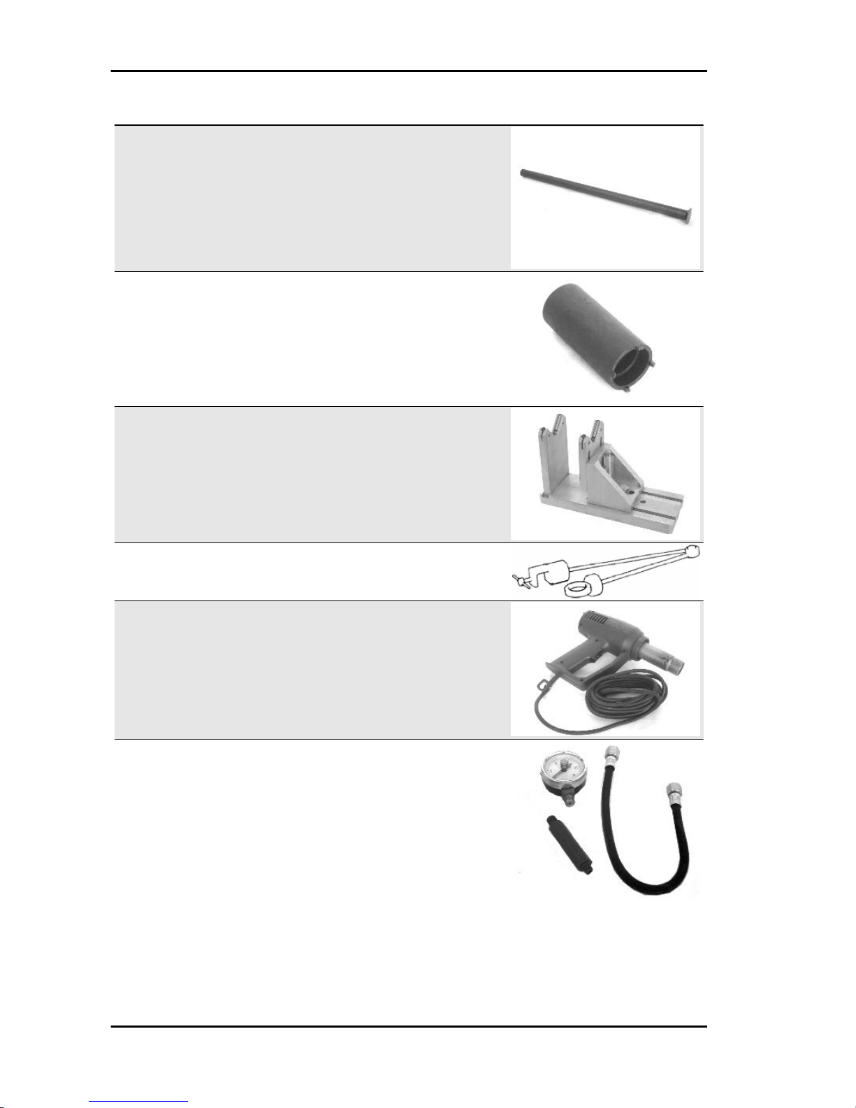
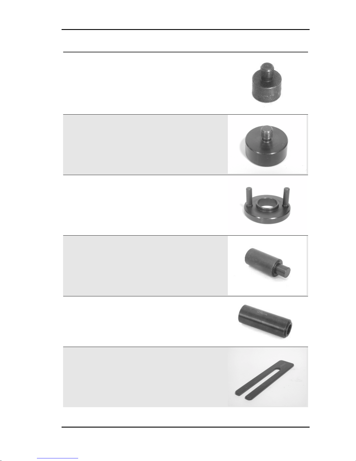
Stores code Description
020004Y Punch for removing fifth wheels from
headstock
020055Y Wrench for steering tube ring nut
020074Y Support base for checking crankshaft
alignment
020150Y Air heater support
020151Y Air heater
020193Y Oil pressure gauge
Tooling Liberty 125 - 200 4tempi
TOOL - 20
Page 21

Stores code Description
020262Y Crankcase splitting strip
020263Y Driven pulley assembly sheath
020287Y Clamp to assemble piston on cylinder
020306Y Punch for assembling valve sealing rings
020329Y MityVac vacuum-operated pump
020330Y Stroboscopic light to check timing
Liberty 125 - 200 4tempi Tooling
TOOL - 21
Page 22
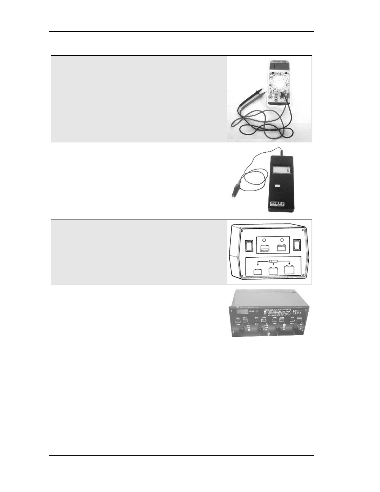
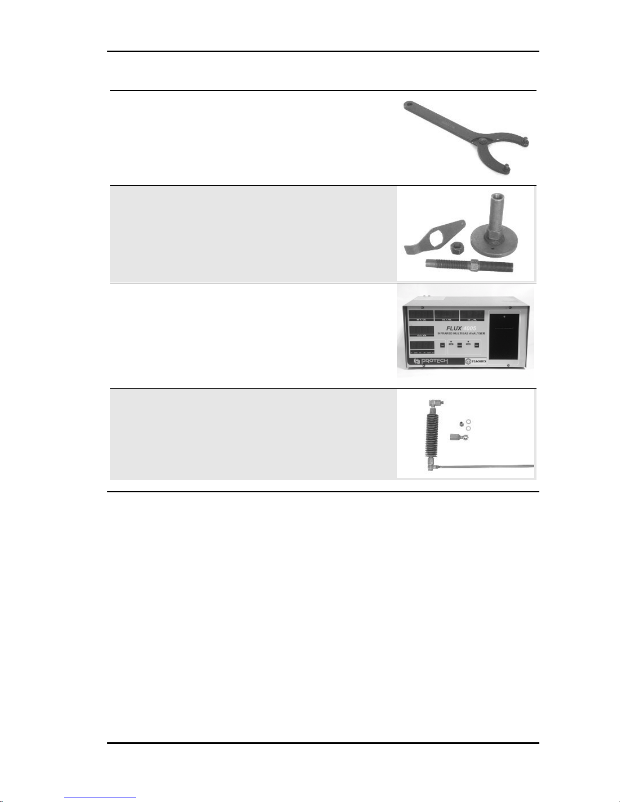
Stores code Description
020331Y Digital multimeter
020332Y Digital rev counter
020333Y Single battery charger
020334Y Multiple battery charger
Tooling Liberty 125 - 200 4tempi
TOOL - 22
Page 23

Stores code Description
020335Y Magnetic support for dial gauge
020357Y 32x35-mm Adaptor
020359Y 42x47-mm Adaptor
020360Y 52x55-mm Adaptor
020363Y 20 mm guide
020364Y 25-mm guide
Liberty 125 - 200 4tempi Tooling
TOOL - 23
Page 24

Stores code Description
020368Y driving pulley lock wrench
020375Y Adaptor 28 x 30 mm
020376Y Adaptor handle
020382Y011 adapter for valve removal tool
020409Y Multimeter adaptor - Peak voltage detec-
tion
Tooling Liberty 125 - 200 4tempi
TOOL - 24
Page 25
Stores code Description
020412Y 15 mm guide
020414Y 28-mm guide
020423Y Driven pulley lock wrench
020424Y Driven pulley roller casing fitting punch
020425Y Punch for flywheel-side oil seal
020426Y Piston fitting fork
Liberty 125 - 200 4tempi Tooling
TOOL - 25
Page 26

Stores code Description
020427Y Piston fitting band
020428Y Piston position check support
020430Y Pin lock fitting tool
020431Y Valve oil seal extractor
020434Y Oil pressure control fitting
020444Y Tool for fitting/ removing the driven pulley
clutch
Tooling Liberty 125 - 200 4tempi
TOOL - 26
Page 27
Stores code Description
020565Y Flywheel lock calliper spanner
020622Y Transmission-side oil guard punch
494929Y Exhaust fumes analyser
020625Y Kit for sampling gas from the exhaust
manifold
Liberty 125 - 200 4tempi Tooling
TOOL - 27
Page 28

INDEX OF TOPICS
MAINTENANCE MAIN
Page 29

Maintenance chart
EVERY 2 YEARS
Action
Brake fluid - change
EVERY 3000 KM
Action
Engine oil - level check/ top-up
AFTER 1000 KM
80'
Action
Engine oil - replacement
Hub oil - change
Oil filter (net filter) - clean
Idle speed (*) - adjustment
Throttle lever - adjustment
Steering - adjustment
Brake control levers - greasing
Brake pads - check condition and wear
Brake fluid level - check
Safety locks - check
Electrical system and battery - check
Tyre pressure and wear - check
Vehicle and brake test - road test
(*) See instructions in the «Idle speed adjustment» section
AFTER 6000 KM, 18000 KM, 54000 KM
150'
Action
Engine oil - replacement
Hub oil level - check
Spark plug electrode gap - check
Air filter - clean
Engine oil - change
Oil filter (net filter) - clean
Valve clearance - adjustment
Variable speed rollers/pads - check
Driving belt - checking
Brake pads - check condition and wear
Brake fluid level - check
Electrical system and battery - check
Centre stand - lubrication
Tyre pressure and wear - check
Vehicle and brake test - road test
AFTER 12000 KM, 60000 KM
160'
Action
Engine oil - replacement
Hub oil level - check
Air filter - clean
Engine oil - change
Oil filter (net filter) - clean
Spark plug - replacement
Idle speed (*) - adjustment
Throttle lever - adjustment
Pads and variator rollers - replacement
Liberty 125 - 200 4tempi Maintenance
MAIN - 29
Page 30

Action
Driving belt - replacement
Odometer gear - greasing
Steering - adjustment
Brake control levers - greasing
Brake pads - check condition and wear
Brake fluid level - check
Transmission elements - lubrication
Safety locks - check
Suspensions - check
Electrical system and battery - check
Headlight - adjustment
Centre stand - lubrication
Secondary air filter - cleaning
Tyre pressure and wear - check
Vehicle and brake test - road test
(*) See instructions in the «Idle speed adjustment» section
AFTER 24000 KM, 48000 KM
175'
Action
Engine oil - replacement
Hub oil - change
Air filter - clean
Engine oil - change
Oil filter (net filter) - clean
Spark plug - replacement
Idle speed (*) - adjustment
Throttle lever - adjustment
Pads and variator rollers - replacement
Driving belt - replacement
Cylinder ventilation system - cleaning
Odometer gear - greasing
Steering - adjustment
Brake control levers - greasing
Brake pads - check condition and wear
Brake fluid level - check
Transmission elements - lubrication
Safety locks - check
Suspensions - check
Electrical system and battery - check
Headlight - adjustment
Tyre pressure and wear - check
Secondary air filter - cleaning
Centre stand - lubrication
Vehicle and brake test - road test
(*) See instructions in the «Idle speed adjustment» section
AFTER 30000 KM, 42000 KM, 66000 KM
95'
Action
Engine oil - replacement
Hub oil level - check
Spark plug electrode gap - check
Air filter - clean
Engine oil - change
Oil filter (net filter) - clean
Slide pads and variator rollers - check
Driving belt - checking
Brake pads - check condition and wear
Brake fluid level - check
Electrical system and battery - check
Centre stand - lubrication
Tyre pressure and wear - check
Vehicle and brake test - road test
Maintenance Liberty 125 - 200 4tempi
MAIN - 30
Page 31

AFTER 36000 KM
270'
Action
Engine oil - replacement
Hub oil - change
Spark plug - replacement
Air filter - clean
Engine oil - change
Oil filter (net filter) - clean
Valve clearance - adjustment
Idle speed (*) - adjustment
Throttle lever - adjustment
Pads and variator rollers - replacement
Driving belt - replacement
Odometer gear - greasing
Steering - adjustment
Brake control levers - greasing
Brake pads - check condition and wear
Brake fluid level - check
Flexible brake tubes - replacement
Transmission elements - lubrication
Safety locks - check
Suspensions - check
Electrical system and battery - check
Headlight - adjustment
Secondary air filter - cleaning
Centre stand - lubrication
Tyre pressure and wear - check
Vehicle and brake test - road test
(*) See instructions in the «Idle speed adjustment» section
AFTER 72,000 KM
270'
Action
Engine oil - replacement
Hub oil - change
Spark plug - replacement
Air filter - clean
Engine oil - change
Oil filter (net filter) - clean
Valve clearance - adjustment
Idle speed (*) - adjustment
Throttle lever - adjustment
Pads and variator rollers - replacement
Driving belt - replacement
Odometer gear - greasing
Steering - adjustment
Cylinder ventilation system - check
Brake control levers - greasing
Brake pads - check condition and wear
Brake fluid level - check
Flexible brake tubes - replacement
Transmission elements - lubrication
Safety locks - check
Suspensions - check
Electrical system and battery - check
Headlight - adjustment
Secondary air filter - cleaning
Centre stand - lubrication
Tyre pressure and wear - check
Vehicle and brake test - road test
(*) See instructions in the «Idle speed adjustment» section
Liberty 125 - 200 4tempi Maintenance
MAIN - 31
Page 32
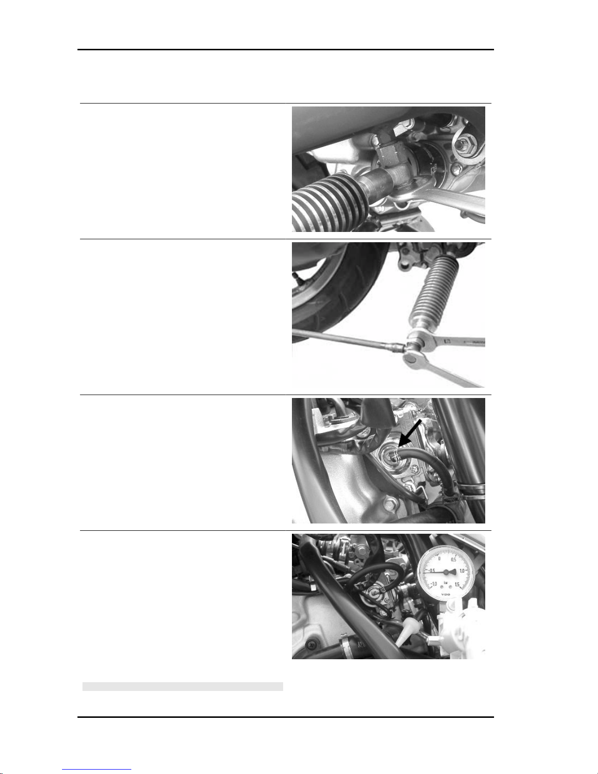
CO check
- Remove the exhaust gases outlet cap on the exhaust pipe
- Using the supplied washer, install the exhaust
gases collection kit fitting onto the pipe, as shown
in the figure.
- Correctly orientate the components as shown in
the picture
- Shut the gas outlet on the tool
- Start the engine and let it warm up
- Shut the engine down
- Disconnect the SAS check valve vacuum hose
shown in the figure.
- Seal the connection using a conical a cap.
- Connect the Mitivac vacuum pump to the SAS
control valve.
- Start the vacuum pump up to a pressure of -0.6
÷ -0.8 bar so to close the valve and cut off the SAS
system.
- Remove the exhaust gas collection kit cap and
connect the analyzer adequately pre-heated.
- Check the analyser output and the engine rpm.
- Adjust the CO concentration.
N.B.
Maintenance Liberty 125 - 200 4tempi
MAIN - 32
Page 33

CHECK THAT THE RESULT IS OBTAINED WITH THE
VALVE GAS IN CLOSED POSITION.
N.B.
ALSO CHECK THE CARBURETION ADJUSTMENT IS OB-
TAINED WITH THE FLOW SCREW OPEN BETWEEN 2 AND
4 TURNS.
N.B.
OTHERWISE, CHECK THE FUEL LEVEL ADJUSTMENT IN
THE TANK AND THE FUEL CIRCUIT.
N.B.
IN CASE OF UNSTABLE CO, CHECK THAT THE CARBU-
RETTOR IS CLEAN AND THAT THE FUEL SUPPLY SYSTEM AND THE DEPRESSION SEALS WORK ADEQUATELY
N.B.
IN CASE OF 1000 PPM UNBURNED HYDROCARBONS
(HC) >, CHECK THE IGNITION SYSTEM, THE TIMING SYSTEM, THE VALVE CLEARANCE AND THE EXHAUST
VALVE TIGHTNESS.
Specific tooling
020329Y MityVac vacuum-operated pump
020332Y Digital rev counter
494929Y Exhaust fumes analyser
020625Y Kit for sampling gas from the exhaust
manifold
Characteristic
CO Check
3.8±0.7 to 1650±50 RPM
Liberty 125 - 200 4tempi Maintenance
MAIN - 33
Page 34

INDEX OF TOPICS
TROUBLESHOOTING TROUBL
Page 35

Engine
Poor performance
POOR PERFORMANCE
Possible Cause Operation
Air filter blocked or dirty. Dismantle the sponge, wash with water and shampoo, then
soak it in a mixture of 50% petrol and 50% of specific oil (Selenia Air Filter Oil), then hand dry without squeezing, allow to
drip dry and then reassemble.
Fuel nozzles or cock clogged or dirty Dismantle, wash with solvent and dry with compressed air
Dirty or faulty vacuum-operated cock Check the filter on the cock, remove the petrol and wash the
tank, if necessary. Replace the cock as a last resource.
Failing automatic starter on the carburettor Check the electrical wiring and mechanical movement, replace
if necessary.
Excessive driving belt wear Check it and replace, if necessary
Lack of compression: parts, cylinder and valves worn Replace the worn parts
Oil level exceeds maximum Check for causes and fill to reach the correct level
Excess of encrustations in the combustion chamber Descale the cylinder, the piston, the head and the valves
Incorrect timing or worn timing system elements Time the system again or replace the worn parts
Muffler obstructed Replace
Inefficient automatic transmission Check the rollers and the pulley movement, replace the dam-
aged parts and lubricate the driven pulley moveable guide with
Montblanc Molybdenum Grease
Wrong valve adjustment Adjust the valve clearance properly
Overheated valves Remove the head and the valves, grind or replace the valves
Valve seat distorted Replace the head assembly
Worn cylinder, Worn or broken piston rings Replace the piston cylinder assembly or just the piston rings
Rear wheel spins at idle
REAR WHEEL ROTATES WITH ENGINE AT IDLE
Possible Cause
Operation
Idling rpms too high Adjust the engine idle speed and the CO%, if necessary.
Clutch fault Check the springs / clutch masses
Starting difficulties
DIFFICULTY STARTING UP
Possible Cause
Operation
Battery flat Check the state of the battery. If it shows signs of sulphation
replace it and bring the new battery into service charging it for
eight hours at a current of 1/10 of the capacity of the battery
itself
Faulty spark plug or incorrect ignition advance Replace the spark plug or check the ignition circuit components
- Engine flooded. Try starting-up with the throttle fully open. If the engine fails to
start, remove the spark plug, dry it and before refitting, make
the motor turn so as to expel the fuel excess taking care to
connect the cap to the spark plug, and this in turn to the ground.
If the fuel tank is empty, refuel and start up.
Incorrect valve sealing or valve adjustment Inspect the head and/or restore the correct clearance
Rpm too low at start-up or engine and start-up system dam-
aged
Check the starter motor and the kick-starter unit
Altered fuel characteristics Drain off the fuel no longer up to standard; then, refill
Vacuum operated cock failure Check that fuel is adequately supplied through the pipe by ap-
plying a vacuum to the suction pipe
Liberty 125 - 200 4tempi Troubleshooting
TROUBL - 35
Page 36

Possible Cause Operation
Failing automatic starter on the carburettor Check the electrical wiring and mechanical movement, replace
if necessary.
Start-up enabling buttons failure Check continuity using an Ohm meter, with the switch pressed;
replace if necessary
Carburettor nozzles clogged or dirty Dismantle, wash with solvent and dry with compressed air
Air filter obstructed or dirty. Dismantle the sponge, wash with water and shampoo, then
soak it in a mixture of 50% petrol and 50% of specific oil (Selenia Air Filter Oil), then hand dry without squeezing, allow to
drip dry and then reassemble.
Excessive oil consumption/Exhaust smoke
EXCESSIVE OIL CONSUMPTION/SMOKEY EXHAUST
Possible Cause Operation
Worn valve guides Check and replace the head unit if required
Worn valve oil guard Replace the valve oil guard
Oil leaks from the couplings or from the gaskets Check and replace the gaskets or restore the coupling seal
Worn or broken piston rings or piston rings that have not been
fitted properly
Replace the piston cylinder unit or just the piston rings
Insufficient lubrication pressure
POOR LUBRICATION PRESSURE
Possible Cause
Operation
By-Pass remains open Check the By-Pass and replace if required. Carefully clean the
By-Pass area.
Oil pump with excessive clearance Perform the dimensional checks on the oil pump components
Oil filter too dirty Replace the cartridge filter
Oil level too low Restore the level using the recommended oil type (Selenia HI
Scooter 4 Tech)
Engine tends to cut-off at full throttle
THE MOTOR TENDS TO STOP AT MAXIMUM THROTTLE
Possible Cause
Operation
Maximum jet clogged Remove the carburettor, wash with solvent and dry with com-
pressed air
Water or condensate in the carburettor tank Remove the tank, wash with solvent and dry with compressed
air
Level in tank too low Restore the level in the tank by bending on the float the thrust-
ing reed of the petrol inlet rod so as to have the float parallel to
the tank level with the carburettor inverted.
Engine tends to cut-off at idle
THE ENGINE TENDS TO STOP AT IDLE SPEED
Possible Cause
Operation
Incorrect idle adjustment Adjust using the rpm indicator
Incorrect timing Time the system and check the timing system components
The starter remains on Check: electric wiring, circuit not interrupted, mechanical
movement and power supply; replace if necessary
Faulty spark plug or incorrect ignition advance Replace the spark plug or check the ignition circuit components
Pressure too low at the end of compression Check the thermal group seals and replace worn components
Minimum nozzle dirty Wash the nozzle with solvent and dry with compressed air
Troubleshooting Liberty 125 - 200 4tempi
TROUBL - 36
Page 37

High fuel consumption
EXCESSIVE FUEL CONSUMPTION
Possible Cause Operation
Air filter blocked or dirty. Clean according to the procedure
Starter inefficient Check: electric wiring, circuit continuity, mechanical sliding and
power supply
Loose nozzles Check the maximum and minimum nozzles are adequately
fixed in their fittings
Incorrect float level Restore the level in the tank by bending on the float the thrust-
ing reed of the petrol inlet rod so as to have the float parallel to
the tank level with the carburettor inverted.
Transmission and brakes
Clutch grabbing or performing inadequately
IRREGULAR CLUTCH PERFORMANCE OR SLIPPAGE
Possible Cause Operation
Slippage or irregular functioning Check that there is no grease on the masses.
Check that the faying surface between the clutch masses and
the clutch bell is mainly in the middle and with equivalent spec-
ifications on the three masses.
Check that the clutch bell is not scored or worn abnormally
Never run the engine without the clutch bell
Insufficient braking
INEFFICIENT OR NOISY BRAKING
Possible Cause
Operation
Worn brake pads or shoes Replace the brake pads or shoes and check for brake disk or
drum wear conditions.
Front brake disk loose or deformed Check the brake disc screws are locked; use a dial gauge and
a wheel mounted on the vehicle to measure the axial shift of
the disc.
Air bubbles inside the hydraulic braking system Carefully bleed the hydraulic braking system, (there must be
no flexible movement of the brake lever).
Fluid leakage in hydraulic braking system Failing elastic fittings, plunger or brake pump seals, replace
Excessive backlash in the rear brake control cable Adjust the backlash with the appropriate adjuster located on
the back part of the crankcase.
Brakes overheating
BRAKES OVERHEATING
Possible Cause
Operation
Rubber gaskets swollen or stuck Replace gaskets.
Compensation holes on the pump clogged Clean carefully and blast with compressed air
Brake disc slack or distorted Check the brake disc screws are locked; use a dial gauge and
a wheel mounted on the vehicle to measure the axial shift of
the disc.
Defective piston sliding Check calliper and replace any damaged part.
Liberty 125 - 200 4tempi Troubleshooting
TROUBL - 37
Page 38

Electrical system
Battery
BATTERY
Possible Cause Operation
Battery The battery is the electrical device in the system that requires
the most frequent inspections and thorough maintenance. If the
vehicle is not used for some time (1 month or more) the battery
needs to be recharged periodically. The battery runs down
completely in the course of 5 ÷ 6 months. If the battery is fitted
on a motorcycle, be careful not to invert the connections, keep-
ing in mind that the black ground wire is connected to the
negative terminal while the red wire is connected to the terminal
marked+. Follow the instructions in the ELECTRICAL SYSTEM
chapter for the recharging of the batteries.
Turn signal lights malfunction
TURN INDICATOR NOT WORKING
Possible Cause Operation
Electronic ignition device failure With the key switch set to "ON" jump the contacts 1 (Blue-
Black) and 5 (Orange) on the control unit connector.
If by operating the turn indicator control the lights are not stead-
ily on, replace the control unit; otherwise, check the cable
harness and the switch.
Steering and suspensions
Heavy steering
STEERING HARDENING
Possible Cause
Operation
Steering hardening Check the tightening of the top and bottom ring nuts. If irregu-
larities continue in turning the steering even after making the
above adjustments, check the seats in which the ball bearings
rotate: if they are recessed or if the balls are squashed, replace
them.
Excessive steering play
EXCESSIVE STEERING CLEARANCE
Possible Cause
Operation
Excessive steering clearance Check the tightening of the top ring nut. If irregularities continue
in turning the steering even after making the above adjust-
ments, check the seats in which the ball bearings rotate: re-
place if they are recessed.
Troubleshooting Liberty 125 - 200 4tempi
TROUBL - 38
Page 39

Noisy suspension
NOISY SUSPENSION
Possible Cause Operation
Noisy suspension If the front suspension is noisy, check: that the front shock ab-
sorber works properly and the ball bearings are good condition.
Finally, check the locking torque of the wheel axle nut, the
brake calliper and the disc. Check that the swinging arm con-
necting the engine to the chassis and the rear shock absorber
work properly.
Suspension oil leakage
OIL LEAKAGE FROM SUSPENSION
Possible Cause Operation
Oil leakage from suspension Replace the rear shock absorber or the front fork cartridge.
Liberty 125 - 200 4tempi Troubleshooting
TROUBL - 39
Page 40

INDEX OF TOPICS
ELECTRICAL SYSTEM ELE SYS
Page 41
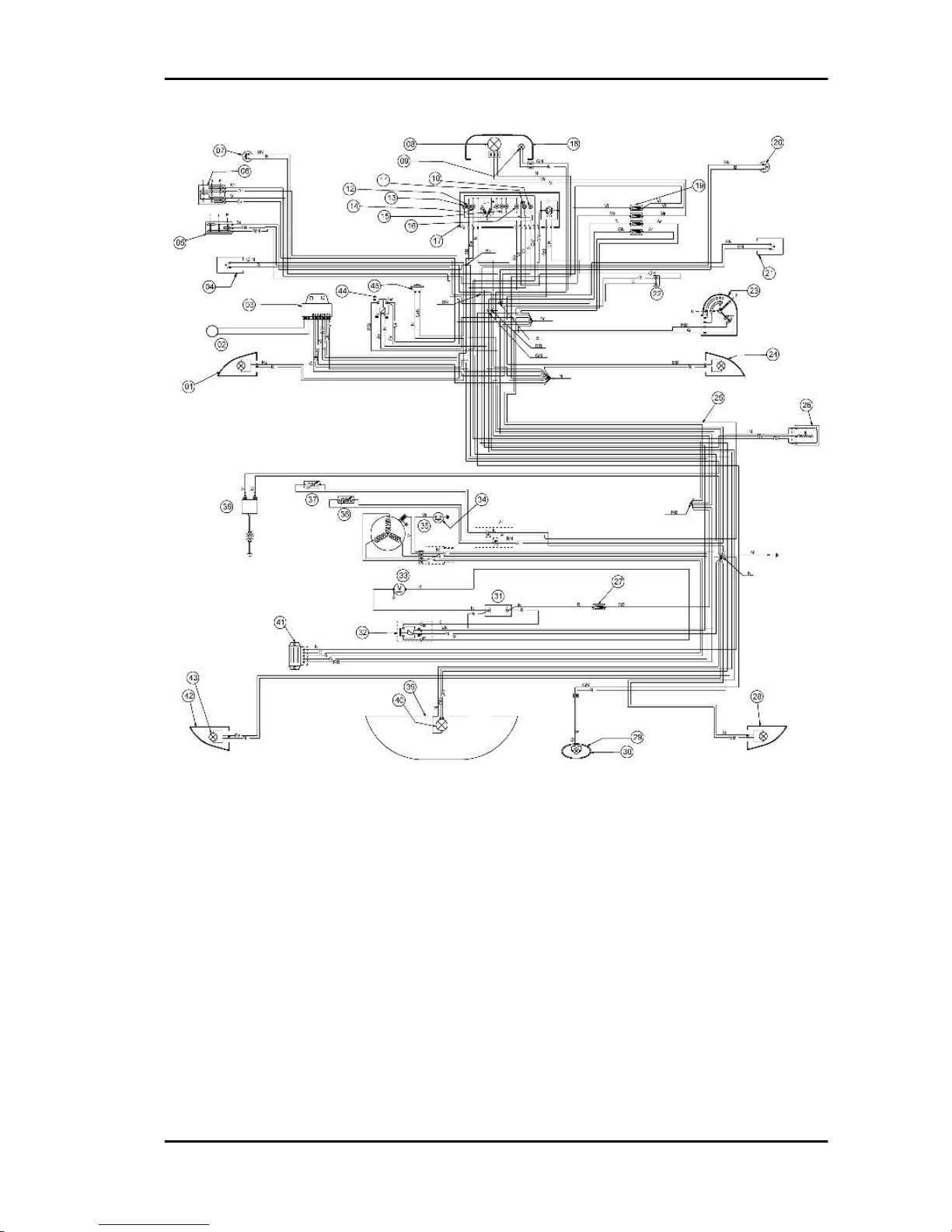
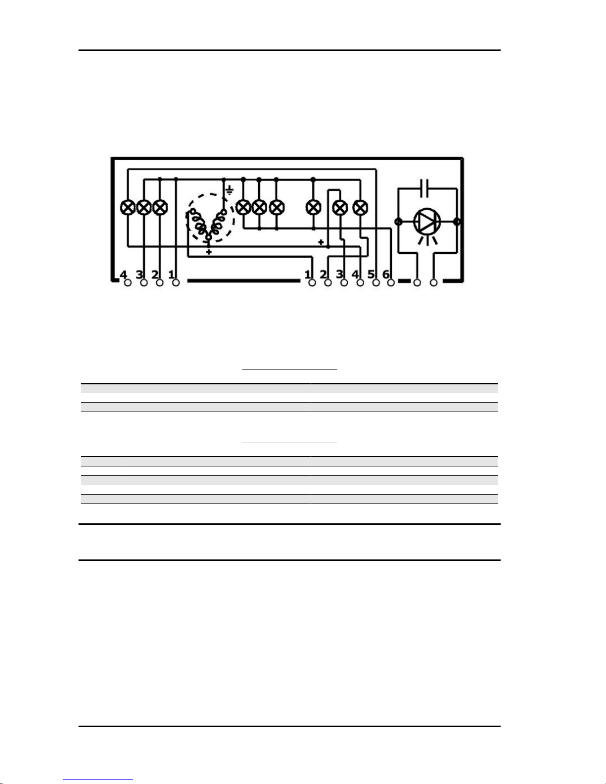
Legend:
1. Front LHS turn signal lights (2 bulbs for each lamp)
2. Immobiliser antenna
3. Electronic ignition device with integrated turn signal and choke controller.
4. Horn button
5. Turn signal switch
6. Light switch
7. Stop light switch on rear brake
8. Dual-setting light bulb 12V - 55/60W
9. Headlamp light bulb
10. High beam warning light
11. Low oil pressure warning light
12. Turn signal warning light (RHS)
Liberty 125 - 200 4tempi Electrical system
ELE SYS - 41
Page 42

13. Low fuel warning light
14. Turn signal warning light (LHS)
15. Dashboard light bulbs
16. Headlamp warning light
17. Odometer with warning lights and level gauges (7 and 2 light bulbs respectively)
18. Headlight
19. Two fuse holders with four fuses (7.5 A)
20. Front brake stop light switch
21. Starter button
22. Immobiliser diagnostic port
23. Key-switch
24. Front RHS turn signal light
25. Cable harness
26. Fuel level sender
27. Fuse holder assembly
28. Rear RHS turn signal light
29. License plate light bulb
30. License plate lamp
31. Battery
32. Starter relay
33. Starter motor
34. Low oil pressure sensor
35. Pick-up
36. Automatic choke device
37. Carburettor heater
38. H.T. coil
39. Taillight assembly
40. Stop and taillight bulb
41. Voltage regulator
42. Rear LHS turn signal light
43. Two amber bulbs for turn signal
44. Relay
45. Horn
Wires colour coding:
B = White
Bl = Blue
G = Yellow
Mr = Brown
Electrical system Liberty 125 - 200 4tempi
ELE SYS - 42
Page 43

N = Black
BV = White-Green
GN = Yellow-Black
Gr = Grey
Rs = Pink
R = Red
Vi = Purple
V = Green
VN = Green-Black
BN = White-Black
BBl = White-Blue
GV = Yellow-Green
Ar = Orange
Az = Light Blue
GrBl = Grey-Blue
GrN = Grey-Black
RBl = Red-Blue
GR =Yellow-Red
BlN = Blue-Black
Conceptual diagrams
Ignition
Liberty 125 - 200 4tempi Electrical system
ELE SYS - 43
Page 44

IGNITION
Specification Desc./Quantity
1 electronic control unit
2 Magneto flywheel
3 Pick - up
4 HV coil
5 Spark plug
6 Voltage regulator
Headlights and automatic starter section
HEADLIGHTS AND AUTOMATIC STARTER SECTION
Specification
Desc./Quantity
1 electronic control unit
2 Carburettor heater
3 Automatic starter
4 Key switch
5 Main fusible 15A
6 Battery (125) 12V - 9Ah
7 Battery (200) 12V - 12Ah
8 Headlamp relay
9 Light switch
10 High-beam fuse 7,5A
11 Low-beam and dashboard lights fuse 7,5A
12 Low-beam light bulb 12V - 55W
13 High-beam light bulb 12V-55W
14 High-beam lamp warning light 12V - 1.2W
15 Front side-light bulb 12V - 5W
16 Four dashboards illuminating bulbs 12V - 1,2W
17 Taillight bulb 12V - 5W
18 License plate bulb 12V - 5W
19 Low-beam fuse 7,5A
Electrical system Liberty 125 - 200 4tempi
ELE SYS - 44
Page 45

Battery recharge and starting
BATTERY RECHARGE AND START-UP SECTION
Specification
Desc./Quantity
1 Magneto flywheel
2 Voltage regulator
3 Pick - up
4 Main fusible 15A
5 Battery (125) 12V - 9Ah
6 Battery (200) 12V - 12Ah
7 Starter relay
8 Starter motor
9 Start up button
10 Front and rear brake light button
11 Brake light filament 12V-21W
12 Fuse 7.5 A
13 Key switch
14 electronic control unit
Liberty 125 - 200 4tempi Electrical system
ELE SYS - 45
Page 46

Level indicators and enable signals section
START PERMISSIVE BUTTONS AND LEVEL INDICATORS
Specification
Desc./Quantity
1 electronic control unit
2 Battery (200) 12V - 12Ah
3 Battery (125) 12V - 9Ah
4 Main fusible 15A
5 Key switch
6 Engine oil pressure sensor
7 Low oil pressure warning light 12V - 1,2W
8 Low fuel warning light 12V - 1.2W
9 Fuel gauge
10 Fuel level sender
11 Fuse 7.5 A
12 Immobilizer aerial
13 Low engine oil pressure sensor
14 Immobiliser LED
15 Front and rear brake light button
16 Taillight bulb 12V - 5W
17 Starter motor
18 Starter relay
19 Start up button
Electrical system Liberty 125 - 200 4tempi
ELE SYS - 46
Page 47

Turn signal lights
TURN INDICATORS AND HORN
Specification
Desc./Quantity
1 electronic control unit
2 Indicators switch
3 4 Turn indicator bulbs 12V-10W
4 Turn signal warning light bulbs 12V - 2W
5 Main fusible 15A
6 Battery (125) 12V - 9Ah
7 Battery (200) 12V - 12Ah
8 Horn
9 Fuse 7.5 A
10 Key switch
11 Horn button
Liberty 125 - 200 4tempi Electrical system
ELE SYS - 47
Page 48
Instruments and warning lights control board
4-PIN CONNECTOR
Specification
Desc./Quantity
1 Ground lead (-)
2 Left turn indicator
3 Right turn indicator
4 Contact not connected
6-PIN CONNECTOR
Specification
Desc./Quantity
1 Fuel gauge
2 High-beam warning light
3 Engine oil warning light
4 Fuse 7.5 A
5 Low fuel warning light 12V - 1.2W
6 Instrument panel lighting and headlamp warning light
Checks and inspections
Electrical system Liberty 125 - 200 4tempi
ELE SYS - 48
Page 49
Immobiliser
The electric ignition system is fed with direct current and is protected by an antitheft immobilizer
integrated to the control unit.
The ignition system consists of:
- electronic control unit
- immobilizer aerial
- master and service keys with built-in transponder
- H.V. coil
- diagnosis LED
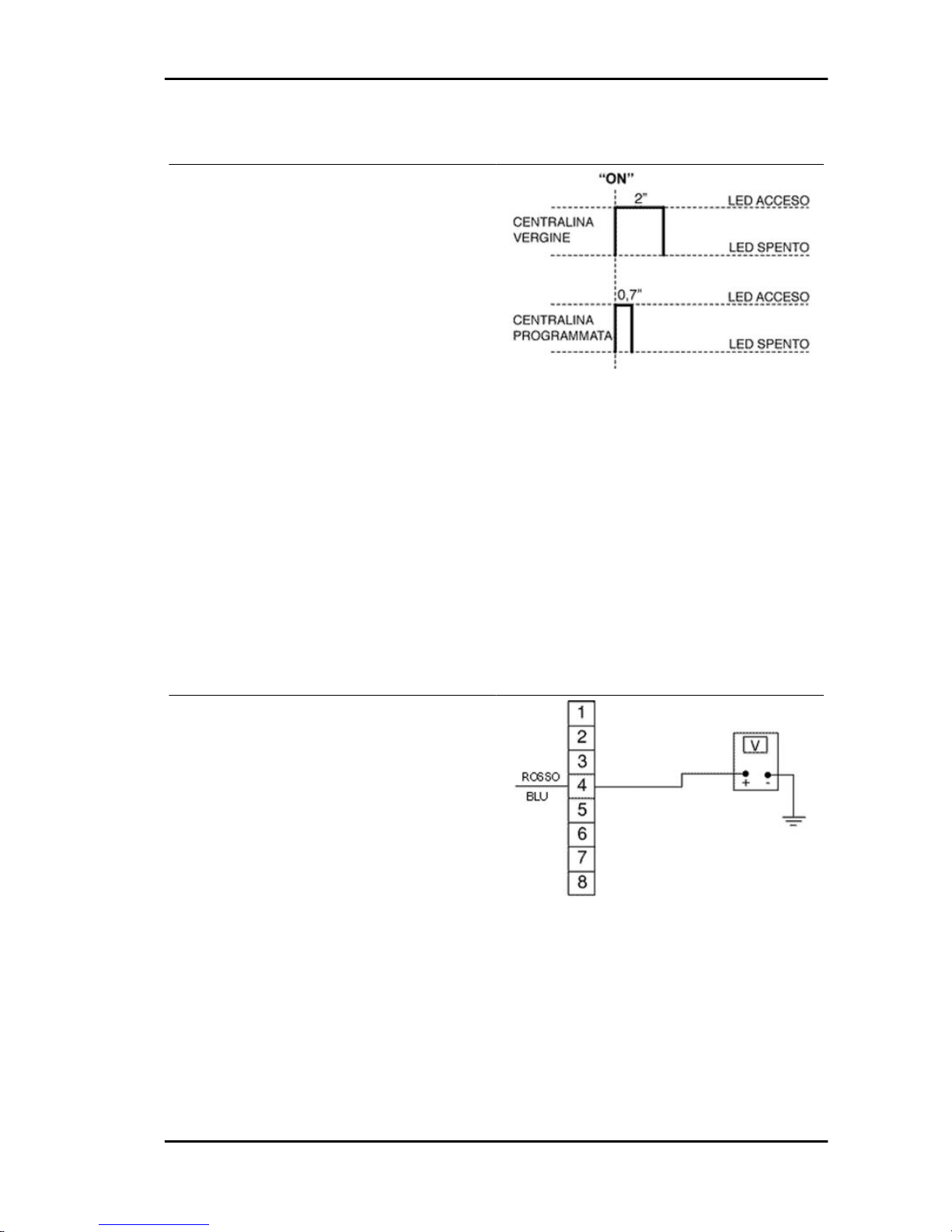
The diagnosis LED also works as a blinking light
to deter theft. This function is activated every time
the key switch is set to «OFF», when the side
stand is lowered or the engine emergency cut-off
switch is set to «OFF». It remains activated for 48
hours in order not to affect the battery charge.
When the ignition switch is turned to «ON», the
deterring blinker function is deactivated. Subsequently, a flash confirms the switching to « ON».
The duration of the flash depends on the electronic
control unit program (see figure).
Whenever the LED is off and remains so, even
when switching it to «ON», it is necessary to check
if:
- the battery is charged
- 15A main fuse is working correctly.
Connect the immobilizer tester to the diagnosis
socket (see ET4 125 manual) located behind the
front left fuse box flap.
If the serial LED remains off, check the electronic
control unit supply as follows:
Liberty 125 - 200 4tempi Electrical system
ELE SYS - 49
Page 50
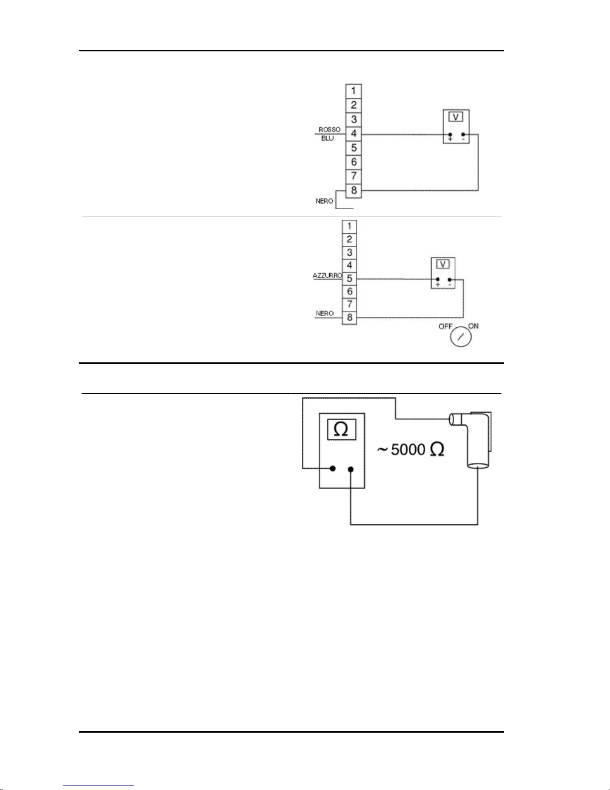
Detach the connector from the ECU and check the
following:
- Presence of battery potential difference between
terminal 4 (Red/Blue) and earth
- Presence of battery potential difference between
terminals 4 (Red/Blue) and 8 (black), as shown in
the figure.
- Presence of battery potential difference between
terminals 5 and 8 with the key-switch onto «ON».
If no anomalies are found, replace the electronic
control unit.
Virgin circuit
If the ignition system has not been programmed,
the engine can be started but it will run limited to
2000 rpm. When trying to accelerate, some evident loss of power may be felt.
Program the system with the MASTER (Brown)
and SERVICE (Blue) keys as follows:
- Insert the MASTER key, turn it to "ON" and keep
it in that position for 2 seconds (limit values: 1 ÷ 3
seconds).
- Alternatively insert all the available black keys
and turn each one of them to "ON" for 2 seconds.
- Insert the MASTER key again and turn it to "ON"
for 2 seconds.
The maximum time to change keys is 10 seconds.
A maximum of 7 service keys (blue) can be programmed at one time.
Sequence and times must be strictly observed or
it will be necessary to repeat the procedure from
the start.
Electrical system Liberty 125 - 200 4tempi
ELE SYS - 50
Page 51

Once the control unit has been programmed, the
control unit is inseparably matched with the MASTER key transponder.
This matching allows programming further service
keys in case of loss, replacement, etc. Each new
time new data is programmed the previously stored one is deleted.
If a service key setting is lost, it is essential to
carefully check the efficiency of the high voltage
system:
Shielded cap resistance ~ 5000 Ω.
In any case, it is advisable to use resistive spark
plugs as shown in the figure.
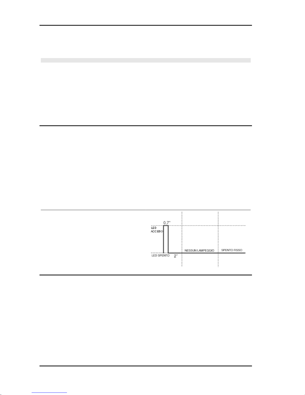
Diagnostic codes
The flash indicating the switching to "ON" (0.7-sec
flash) can be followed by a phase of programmed
failure warnings.
That is, the LED is off for 2 seconds, and then diagnosis codes are transmitted with 0.5-sec flashes.
After the failure code indication, a steadily on LED
signals that ignition is disabled; see the table:
2-FLASH CODE
Example with programmed electronic control unit,
no transponder and/or aerial malfunction
Ignition disabled-Vehicle immobilised
3-FLASH CODE
Example with programmed electronic control unit,
aerial working properly and unknown transponder
code.
Ignition disabled-Vehicle immobilised
Diagnostic code - 2 flashes
When the 2-flash code is detected, carry out the following checks:
- Check if the failure continues even after changing key (including the MASTER key). If the failure
persists with any key, disconnect the aerial connector from the electronic control unit and check the
aerial continuity with the multimeter.
Liberty 125 - 200 4tempi Electrical system
ELE SYS - 51
Page 52
If it does not work, replace the aerial.
If no faults are found, replace the control unit.
CAUTION
BEFORE PROGRAMMING THE NEW ELECTRONIC CONTROL UNIT CHECK THAT NO FAILURE
CODE IS INDICATED. THIS IS TO AVOID SPOILING A NEW CONTROL UNIT UNNECESSARILY.
Specific tooling
020331Y Digital multimeter
Electric characteristic
Resistance value
~ 7 ÷ 9 Ohm
Diagnostic code - 3 flashes
If the 3-flash code is detected, check if the failure occurs when the MASTER key in inserted into the
key switch.
- If the failure disappears when the MASTER key is used, proceed with coding a new service key (Blue).
- If the failure persists, it means that the MASTER key and the control unit are not linked; in this case,
replace the control unit and then encode the keys.
The immobilizer system is efficient when, after switching over to «ON», only a 0.7-sec flash is detected
(see diagram).
In this case, the engine can be started.
Example with programmed control unit, transponder, programmed key and working aerial. The
ignition is enabled (regular use conditions)
Ignition circuit
All the control operations of the system that entail disconnecting cables (to check connections and the
devices making up the ignition circuit) must be done with the engine off: if this is not done, the controls
might be irretrievably damaged.
The battery provides the basic power supply. The system is adjusted so that the start-up system immediately detects an eventual battery voltage drop, and this is practically irrelevant for the ignition
system.
The Pick-Up is connected to the control unit by a single cable; therefore, the control unit is connected
to the Pick-Up by the chassis and the engine ground lead.
Electrical system Liberty 125 - 200 4tempi
ELE SYS - 52
Page 53

To avoid disturbances in the ignition system during start-up, it is very important that the engine-chassis
ground connection bonding is efficient.
No spark plug
When noticing no spark plug proceded as follows:
- Pick-Up inspection.
Detach the ECU connector and check for continuity between terminals 2 (Green) and 8 (Black).
The inspection must include the pick-up and it's
power cable.
If an open circuit is found, repeat the inspection
between the flywheel connector and earth. If unacceptable values are found, proceed by replacing
the pick-up, otherwise repair the cable.
Electric characteristic
Pick-up resistance value
Pick-up resistance value: 105 ÷ 124 Ohm
- H.T. coil primary circuit inspection
Detach the connector from the ECU and check for
continuity between terminals 3 (purple) and 8
(black) (see figure).
If unacceptable values are found, repeat the inspection directly from the positive and negative
terminals of the H.T. coil primary circuit.
If the values are within the prescribed limit, proceed by repairing the wiring or reattaching all wirings, otherwise replace the H.T. coil.
Electric characteristic
High voltage coil primary resistance value
High voltage coil primary resistance value: 0.4 ÷
0.5 Ohm
- HV coil secondary check
Disconnect the spark plug cap from the HV cable and measure the resistance between the HV cable
terminal and the HV coil negative terminal (see figure).
If non-conforming values are measured, replace the HV coil. To carry out a more complete diagnosis,
check the peak voltage with the multimeter adaptor.
Specific tooling
Liberty 125 - 200 4tempi Electrical system
ELE SYS - 53
Page 54

020409Y Multimeter adaptor - Peak voltage detection
Electric characteristic
High voltage coil secondary resistance value
High voltage coil secondary resistance value: ~ 3000 ± 300 Ohm
- Pick-Up
Detach the ECU connector and connect the positive terminal to connector no. 2 and the negative
terminal to connector no. 8 (see figure).
Crank the engine using the starter motor and
check the tension produced by the pick-up.
If unacceptable values are found, replace the PickUp.
N.B.
THE MULTIMETER MUST BE SELECTED TO DETECT
CONTINUOUS VOLTAGE.
Electric characteristic
Pick-Up voltage value
Pick-Up voltage value: > 2 Volt
- H.V. coil
With the control unit and HV coil connected to the
circuit, measure the voltage of the coil primary during the start-up test with the voltage peak adaptor
and connect the positive terminal to the earth one
and the negative to the coil positive connector.
If non-conforming values are measured, replace
the control unit.
THE POSITIVE TERMINAL OF THE HV COIL PRIMARY IS
BLACK.
Electric characteristic
High voltage coil voltage value
High voltage coil voltage value: > 100 Volt
Electrical system Liberty 125 - 200 4tempi
ELE SYS - 54
Page 55
Battery recharge circuit
The recharge system is provided with a three phase alternator with permanent flywheel.
The alternator is directly connected to the voltage regulator.
In turn, the latter is directly connected to earth and to the battery positive passing through the 15A safety
fuse.
This system therefore requires no connection to the key switch.
The three- phase generator provides good recharge power and at low revs a good compromise is
achieved between generated power and idle stability.
For this reason, it is very important that the idle speed is adjusted as prescribed.
Specific tooling
020333Y Single battery charger
020334Y Multiple battery charger
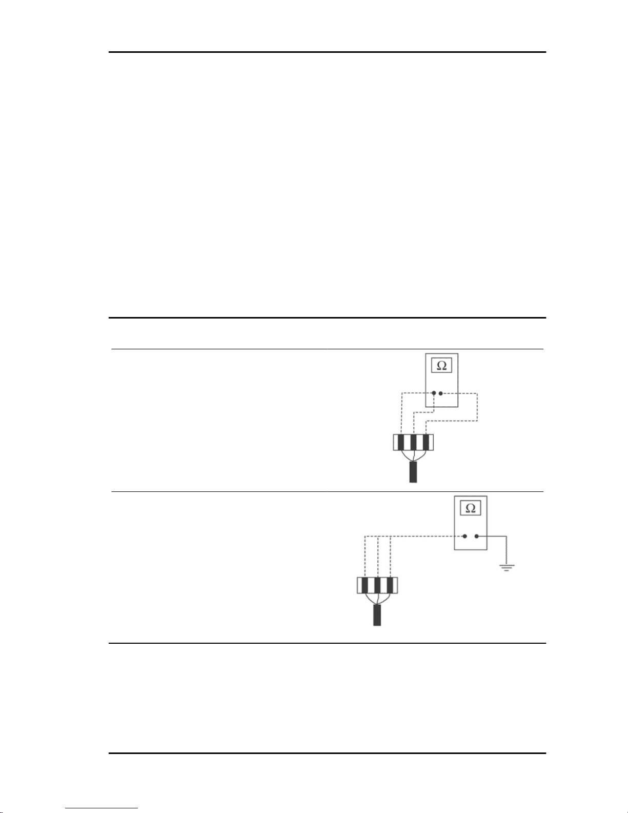
Stator check
Disconnect the connector from the voltage regulator and check there is continuity between any
yellow cable and the other two cables.
Electric characteristic
Ohm value:
0.7 ÷ 0.9 Ohm
Also check that all yellow cables are insulated from
the ground connection.
If non-conforming values are detected, repeat the
checks directly to the stator. In case of further repetitions of incorrect values replace the stator or
repair the wiring.
Liberty 125 - 200 4tempi Electrical system
ELE SYS - 55
Page 56
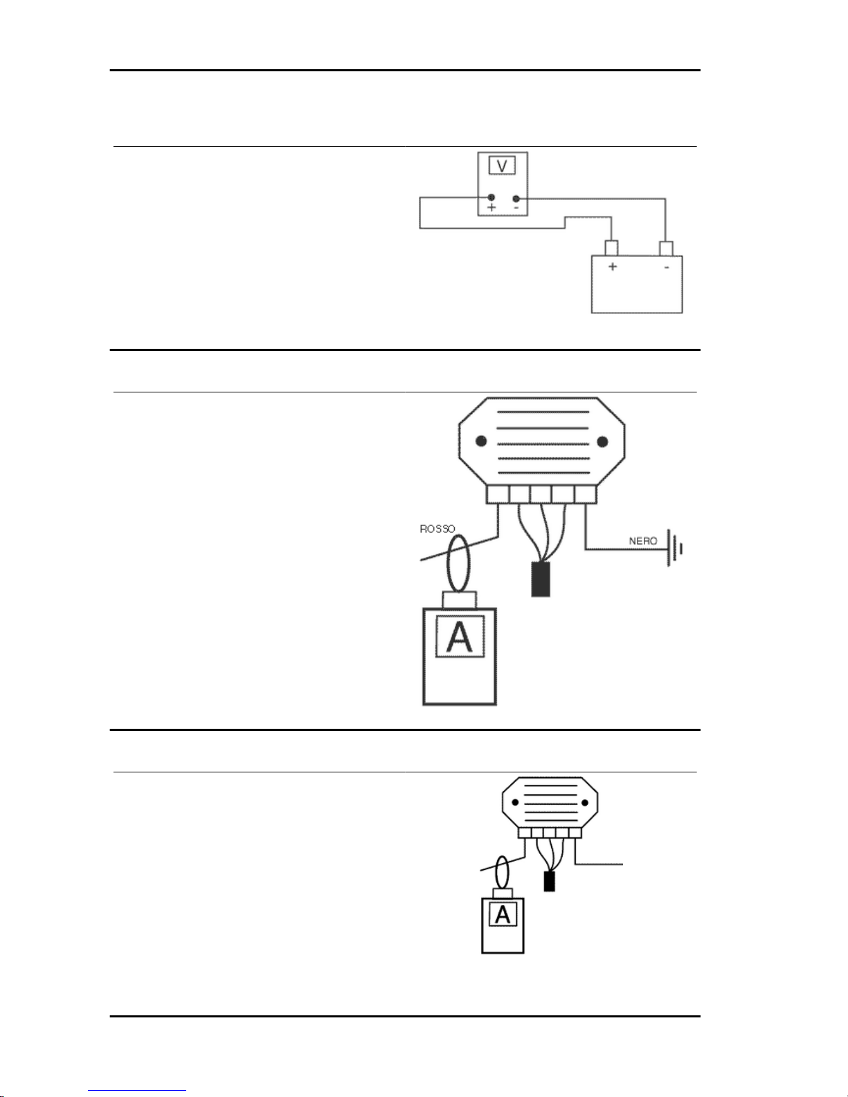
Voltage regulator check
With a perfectly charged battery and lights off,
measure voltage at the battery poles with a high
running engine.
The voltage should not exceed 15.2 Volt.
In case higher voltages are detected, replace the
regulator.
In case of voltage values lower than 14 Volt, check
the stator and the corresponding cable harness.
Recharge system voltage check
Connect an ammeter induction clamp to the voltage regulator positive terminal, measure the battery voltage and turning on the vehicles lights with
engine off, wait for the voltage to set at about 12
V. Start the engine and measure the current generated by the system with lights on and a high
running engine.
In case the generated current value is lower than
8A, repeat the test using a new regulator and/stator alternatively.
Choke Inspection
Refer to the engine section to check the resistance
and operating conditions of the component. As regards voltage supply, keep the connector connected to the system and check that the two terminals
receive battery voltage when the engine is on
(see figure).
If no voltage is detected, connect the multimeter
negative terminal to the ground lead and the positive terminal to the automatic starter orange cable;
Electrical system Liberty 125 - 200 4tempi
ELE SYS - 56
Page 57

with the key switch set to "ON" check whether
there is battery voltage; if there is no voltage,
check the wiring connections to the key switch.
If battery potential is found, repeat the inspection
from the connector to the ECU.
After detaching the choke device, start the engine
and, while at idle, check for tension connecting the
positive terminal of the multimetre to terminal 5
(Orange) and the negative to terminal 7 (White/
Black) (see figure).
If no tension is found, replace the ECU; otherwise
check the wiring between the choke device and the
ECU.
Turn signals system check
- If the turn signal lights are faulty, proceed as follows:
- Detach the ECU connector and check for battery
tension between terminal 5 (Orange) and earth,
with the key-switch onto «ON».
- Check the same is present between terminals 5
(Orange) and 8 (Black).
If no tension is measured, check the wiring, otherwise proceed as follows:
- Jumper terminals 1 (Black/Blue) and 5 (Orange),
see figure, and alternately operate the turn signal
switch towards left and right wit the key-switch onto «ON» and check the bulbs go off.
If this happens, replace the ECU, as faulty.
If this does not happen, check the wiring between
the ECU and the turn signal switch, hence repeat
the test.
Liberty 125 - 200 4tempi Electrical system
ELE SYS - 57
Page 58

Sealed battery
If the vehicle is provided with a sealed battery, the only maintenance required is the check of its charge
and recharging, if necessary.
These operations should be carried out before delivering the vehicle, and on a six-month basis while
the vehicle is stored in open circuit.
Besides, upon pre-delivery it is therefore necessary to check the battery charge and recharge it, if
required, before storing the vehicle and, afterwards, every six months.
INSTRUCTIONS FOR THE RENEWAL RECHARGE AFTER OPEN-CIRCUIT STORAGE
1) Voltage check up
Before installing the battery on the vehicle, check the open circuit voltage with a regular tester.
- If voltage exceeds 12.60 V, the battery can be installed without any renewal recharge.
- If voltage is below 12.60 V, a renewal recharge is required as explained in 2).
2) Constant voltage battery charge mode
- Constant voltage charge equal to 14.40 ÷ 14.70V
-Initial charge voltage equal to 0.3 ÷ 0.5 for Nominal capacity
- Charge time:
10 to 12 h recommended
Minimum 6 h
Maximum 24 h
3) Constant current battery charge mode
- Charge current equal to 1/10 of the battery rated capacity
- Charge time: Maximum 5 h
Dry-charge battery
WARNING
- Battery electrolyte is toxic and it may cause serious burns. It contains sulphuric acid. Avoid contact
with eyes, skin and clothing. In case of contact with eyes or skin, flush abundantly with water for about
15 minutes and seek immediate medical attention.
In the event of accidental ingestion of the fluid, immediately drink large quantities of water or milk. Follow
with milk of magnesia, beaten egg or vegetable oil. Seek immediate medical attention
Batteries produce explosive gases; keep clear of free flames, sparks or cigarettes; ventilate the area
when recharging the battery indoors.
Always protect your eyes when working close to batteries.
Keep out of the reach of children.
Electrical system Liberty 125 - 200 4tempi
ELE SYS - 58
Page 59

Commissioning dry-charged batteries :
1) - Remove the short closed tube and the caps,
then pour sulphuric acid into the cells using the
type specified for batteries with a specific gravity
of 1.26, corresponding to 30 Be at a minimum temperature of 15°C until the upper level is reached.
2) - Leave to rest for at least 2 hours; then, restore
the level with sulphuric acid.
3) - Within the following 24 hours, recharge using
the specific battery charger (single) or (multiple) at
a density of about 1/10 of the battery nominal capacity until fully charged; check that the acid density is about 27, corresponding to 31 Be, and that
these values are stabilised.
4) - Once the charge is over, level the acid (by
adding distilled water). Close and clean carefully.
5) Once the above operations have been performed, install the battery on the vehicle ensuring
that it is wired up properly.
1 Hold the vertical tube
2 Look at the level
3 The float must be freed
WARNING
- ONCE THE BATTERY HAS BEEN INSTALLED IN THE VEHICLE IT IS NECESSARY TO REPLACE THE SHORT TUBE
(WITH CLOSED END) NEAR THE + POSITIVE TERMINAL
WITH THE CORRESPONDING LONG TUBE (WITH OPEN
END), THAT YOU FIND FITTED TO THE VEHICLE, TO ENSURE THAT THE GASES THAT FORM CAN ESCAPE
PROPERLY.
Specific tooling
020333Y Single battery charger
020334Y Multiple battery charger
Battery maintenance
The battery is an electrical device which requires careful monitoring and careful maintenance. The
maintenance rules are:
1) Electrolyte level check
The electrolyte level must be checked frequently and must reach the upper level. Only use distilled
water, to restore this level. If it is necessary to add water too frequently, check the vehicle electrical
system: the battery works overcharged and is subject to quick wear.
2)Load status check
Liberty 125 - 200 4tempi Electrical system
ELE SYS - 59
Page 60

After restoring the electrolyte level, check its density using an appropriate densitometer (see the figure).
When the battery is charged, you should detect a density of 30 to 32 Bé corresponding to a specific
weight of 1.26 to 1.28 at a temperature of no lower than 15° C.
A density reading of less than 20° Bé indicates that the battery is completely flat and it must therefore
be recharged.
If the scooter is not used for a given time (1 month or more) it will be necessary to periodically recharge
the battery.
The battery runs down completely in the course of three months. If it is necessary to refit the battery in
the vehicle, be careful not to reverse the connections, remembering that the ground wire (black) marked
(-) must be connected to the -negative clamp while the other two red wires marked (+) must be connected to the clamp marked with the +positive sign.
3) Recharging the battery
Remove the battery from the vehicle removing the negative clamp first.
Regular bench charging must be carried out with the specific battery charger, (single) or (multiple),
setting the battery charger selector to the type of battery to be recharged. Connections to the power
supply source must be implemented by connecting the corresponding poles (+ to+ and - to -).
4) Battery cleaning
The battery should always be kept clean, especially on its top side, and the terminals should be coated
with Vaseline.
WARNING
BEFORE RECHARGING THE BATTERY, REMOVE THE PLUGS OF EACH CELL. KEEP SPARKS
AND NAKED FLAMES AWAY FROM THE BATTERY WHILE RECHARGING.
CAUTION
NEVER USE FUSES WITH A CAPACITY HIGHER THAN THE RECOMMENDED CAPACITY. USING
A FUSE OF UNSUITABLE RATING MAY SERIOUSLY DAMAGE THE VEHICLE OR EVEN CAUSE
A FIRE.
CAUTION
ORDINARY AND DRINKING WATER CONTAINS MINERAL SALTS THAT ARE HARMFUL FOR
THE BATTERY. FOR THIS REASON, YOU MUST ONLY USE DISTILLED WATER.
CAUTION
TO ENSURE MAXIMUM PERFORMANCE THE BATTERY MUST BE CHARGED BEFORE USE.
INADEQUATE CHARGING OF THE BATTERY WITH A LOW ELECTROLYTE LEVEL BEFORE IT
IS FIRST USED SHORTENS THE LIFE OF THE BATTERY.
Specific tooling
020333Y Single battery charger
020334Y Multiple battery charger
Electrical system Liberty 125 - 200 4tempi
ELE SYS - 60
Page 61

INDEX OF TOPICS
ENGINE FROM VEHICLE ENG VE
Page 62

Exhaust assy. Removal
- Remove the 2 fixing nuts from the manifold to the
head
- Undo the 2 screws fixing the muffler to the housing; then remove the whole muffler paying attention to the interference between its supporting
bracket and the cooling cover.
Removal of the engine from the vehicle
•
Remove the spark plug access cover.
•
Remove the helmet compartment.
•
Remove the entire muffler assembly.
•
Disconnect the spark plug cap.
•
Remove the 3 screws on the transmission cover fixing the rear brake transmission.
•
Cut the fixing clamp and disconnect the
transmission air pipe. Disconnect the
engine ground lead after having unscrewed the specific screw on the cover.
Engine from vehicle Liberty 125 - 200 4tempi
ENG VE - 62
Page 63

•
Detach the electrical connections from
starter motor, choke device, carburettor heater and flywheel magneto.
•
Detach the throttle cable and the fuel
hose from the carburettor.
•
Detach the vacuum tube from the fuel
tap on the intake manifold.
•
Remove the rear shock absorber by
loosening the top and bottom fixings.
•
Loosen the engine-swingarm fixing nut
from the right hand side of the vehicle
and then remove the bolt from the left.
WARNING
BE VERY CAREFUL WHEN HANDLING FUEL.
CAUTION
WHEN INSTALLING THE BATTERY, ATTACH THE POSI-
TIVE LEAD FIRST AND THEN THE NEGATIVE ONE.
See also
Helmet bay
Exhaust assy. Removal
Liberty 125 - 200 4tempi Engine from vehicle
ENG VE - 63
Page 64

INDEX OF TOPICS
ENGINE ENG
Page 65

This section describes the operations to be carried out on the engine and the tools to be used.
Automatic transmission
Transmission cover
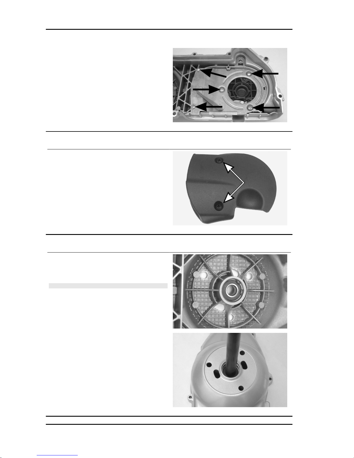
- To remove the transmission cover it is necessary
to remove the rear plastic cover first by inserting a
screwdriver in the corresponding slotted holes.
Using the clutch bell lock wrench, remove the driven pulley axle locking nut and recover the washer.
- Remove the cap/dipstick from the engine oil filling
hole.
- Remove the 10 screws and the earth cable fastened under one of them.
- Remove the transmission cover. If this operation
is performed directly on the vehicle, it is necessary
to remove the cooling air coupling and the three air
filter housing retainers.
Specific tooling
020423Y Driven pulley lock wrench
Air duct
- Unscrew the Torx screws fixing the air manifold
bulkhead and remove the bulkhead.
- Remove the 3 screws, then take out the manifold
as well as the filter.
Liberty 125 - 200 4tempi Engine
ENG - 65
Page 66
Air duct filter
- Unscrew the 2 fixing screws and slide off the filter.
- Clean with water and milid soap.
Removing the driven pulley shaft bearing
- Remove the clip from the inside of the cover.
- Use the specific tools to remove the bearing from
the crankcase.
CAUTION
USE AN APPROPRIATE REST SURFACE TO AVOID DAM-
AGING THE COVER PAINT.
Specific tooling
020376Y Adaptor handle
020375Y Adaptor 28 x 30 mm
Engine Liberty 125 - 200 4tempi
ENG - 66
Page 67
Refitting the driven pulley shaft bearing
- Heat up the crankcase inside with the hot air gun.
- Insert the bearing in its housing, refit the Seeger
ring.
N.B.
ALWAYS REPLACE THE BEARING WITH A NEW ONE
UPON REFITTING.
Specific tooling
020151Y Air heater
020376Y Adaptor handle
020357Y 32x35-mm Adaptor
020412Y 15 mm guide
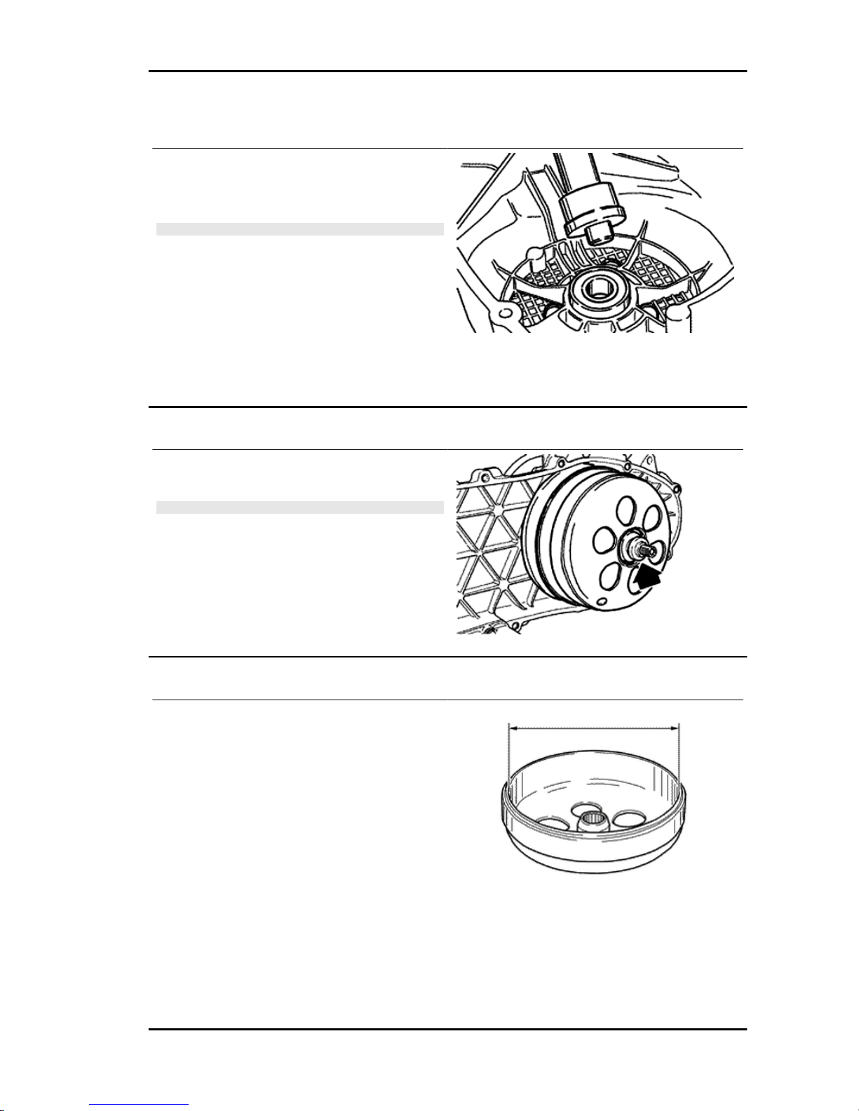
Removing the driven pulley
- Remove the spacer, the clutch bell and the whole
driven pulley unit.
N.B.
THE UNIT CAN ALSO BE REMOVED WITH THE DRIVING
PULLEY MOUNTED.
Inspecting the clutch drum
- Check that the clutch bell is not worn or damaged.
- Measure the clutch bell inside diameter.
Characteristic
Max. value clutch bell
Max. value: Ø 134.5 mm
Clutch bell standard value
Standard value: Ø 134 - 134.2 mm
Liberty 125 - 200 4tempi Engine
ENG - 67
Page 68
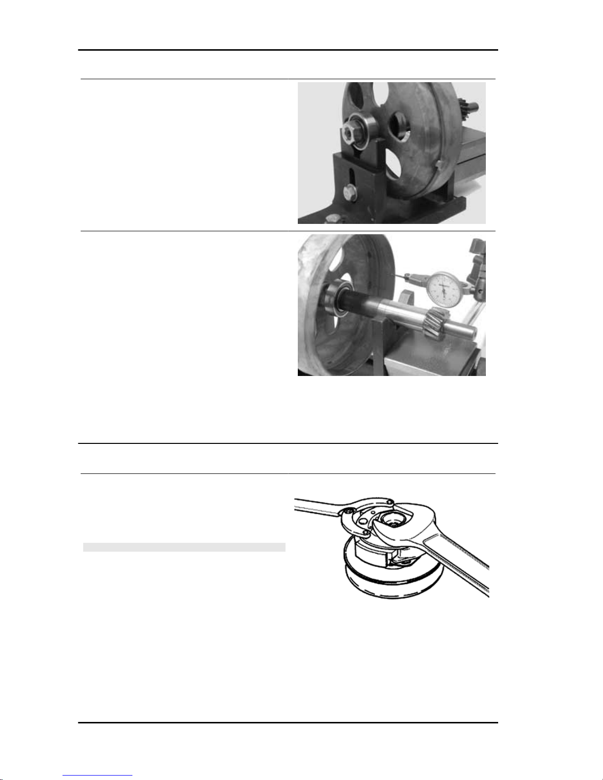
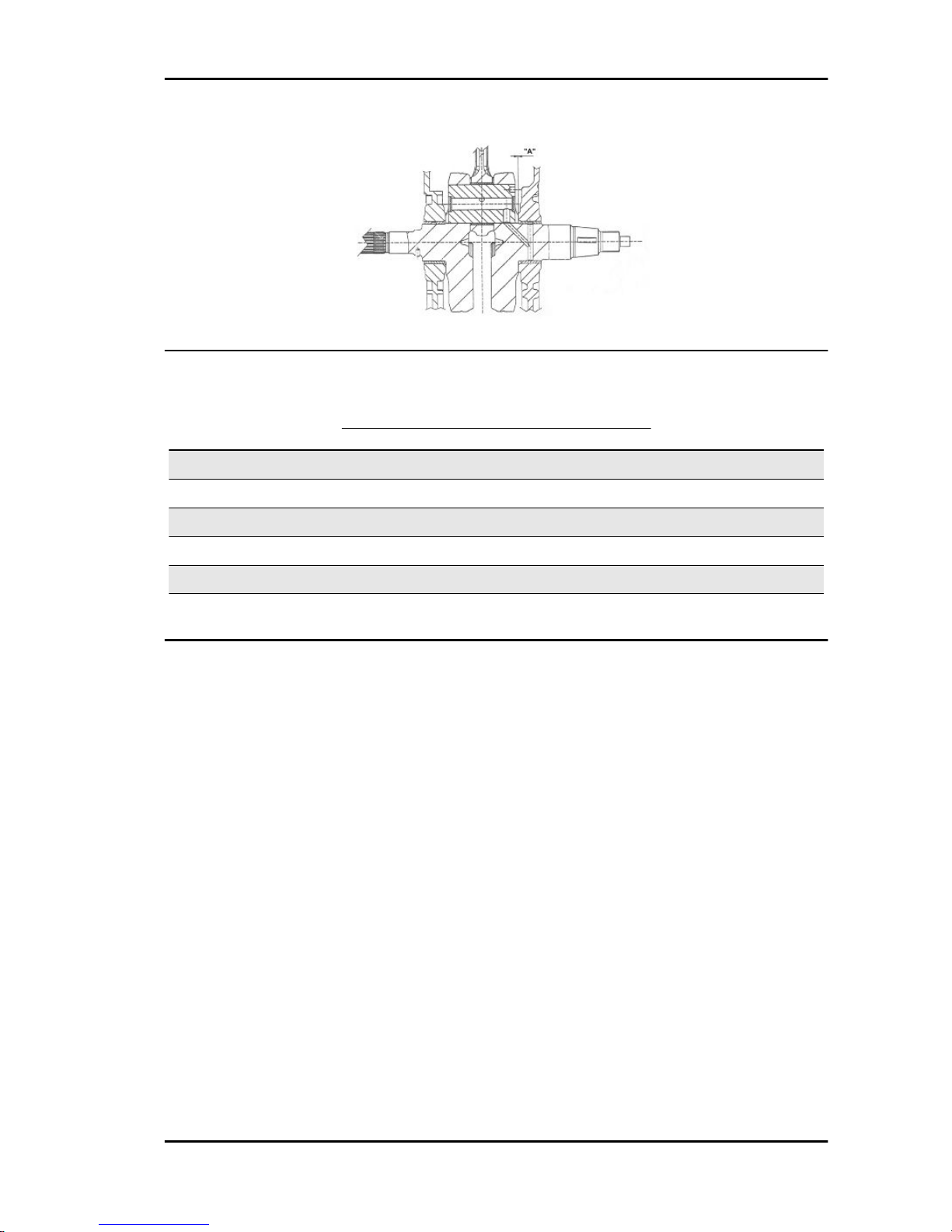
Checking the bell working surface eccentricity
- Install the bell on a driven pulley shaft using 2
bearings (inside diameter: 15 and 17 mm).
- Lock with the original spacer and nut.
- Place the bell/shaft unit on the support to check
the crankshaft alignment.
- Using a feeler pin gauge and the magnetic base,
measure the bell eccentricity.
- Repeat the measurement in 3 positions (Central,
internal, external).
- If faults are found, replace the bell.
Specific tooling
020074Y Support base for checking crankshaft
alignment
020335Y Magnetic support for dial gauge
Characteristic
clutch bell inspection: Limit eccentricity.
Admissible limit eccentricity: 0.15 mm
Removing the clutch
- By means of a calliper spanner, block the clutch
assembly rotation. - With a 46 mm spanner remove the clutch lock nut. - Remove the clutch and
the spring.
CAUTION
UPON REMOVING THE CLUTCH ASSEMBLY LOCK NUT,
PAY ATTENTION TO KEEP THE ASSEMBLY IN ITS SEAT
SO THAT IT DOES NOT COME OUT DUE TO THE SPRING
THRUST
Specific tooling
020565Y Flywheel lock calliper spanner
Engine Liberty 125 - 200 4tempi
ENG - 68
Page 69
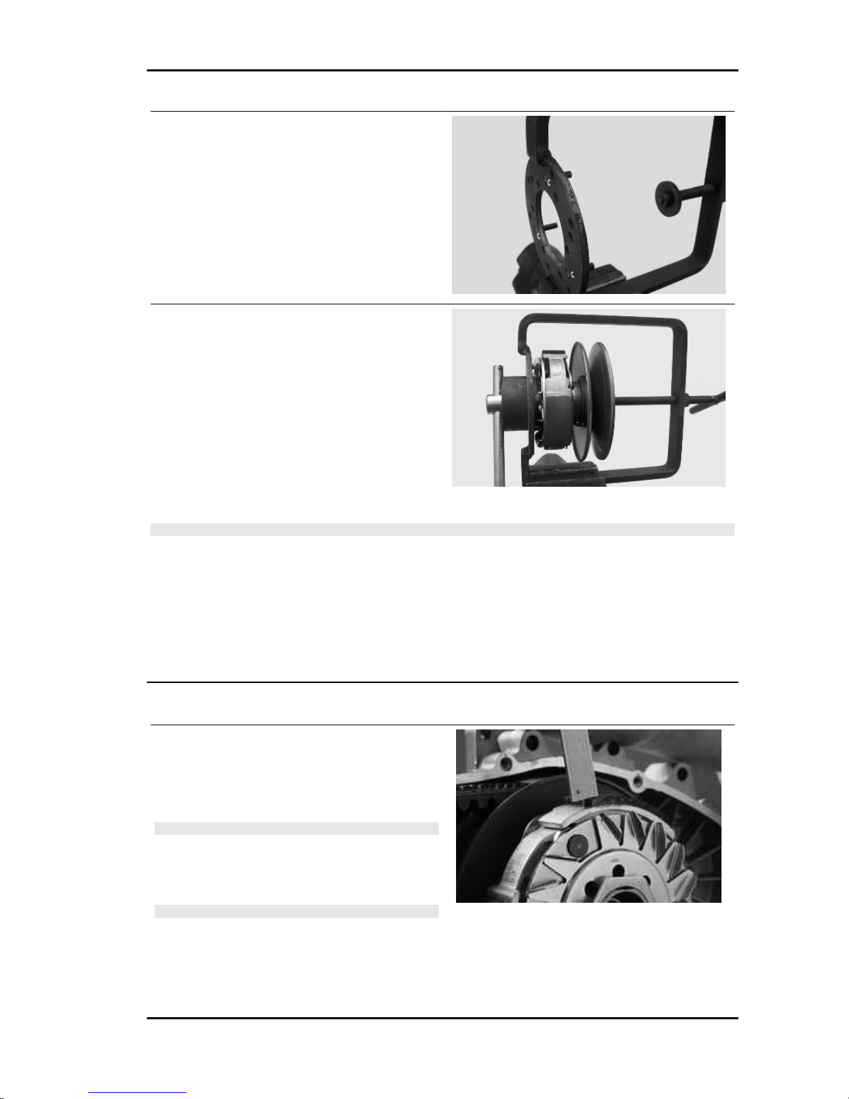
- Prepare the locking tool for the driven pulley with
the pins half-screwed in the tool set to «C».
- Fit the driven pulley unit in the tool so as the bolt
get into the masses clutch support holes. Afterwards make the support screw make contact with
a minimum force.
- Using the specific wrench, inserted 46 mm from
the side, remove the clutch central locking nut.
- Separate the driven pulley into its components (clutch with fan and contrast spring with plastic fittings).
CAUTION
THE TOOL MUST BE FIRMLY FIXED IN THE VICE AND THE CENTRAL SCREW MUST NOT BE
TIGHTENED WITH EXCESSIVE TORQUE AS THIS MAY DAMAGE THE PULLEY OR DEFORM THE
SPECIFIC TOOL.
Specific tooling
020444Y Tool for fitting/ removing the driven pulley clutch
020444Y009 wrench 46 x 55
Inspecting the clutch
- Check the thickness of the clutch mass friction
material.
- The masses must not show traces of lubricants;
otherwise, check the driven pulley unit seals.
N.B.
UPON RUNNING-IN, THE MASSES MUST EXHIBIT A CEN-
TRAL FAYING SURFACE AND MUST NOT BE DIFFERENT
FROM ONE ANOTHER.
VARIOUS CONDITIONS CAN CAUSE THE CLUTCH TO
TEAR.
CAUTION
DO NOT OPEN THE MASSES USING TOOLS TO PREVENT
A VARIATION IN THE RETURN SPRING LOAD.
Characteristic
Check minimum thickness
Liberty 125 - 200 4tempi Engine
ENG - 69
Page 70

1 mm
Pin retaining collar
- Remove the collar with the aid of 2 screwdrivers.
- Remove the 3 guide pins and the movable halfpulley.
Removing the driven half-pulley bearing
- Remove the retaining ring using two flat blade
screwdrivers.
- Using a hammer and pin, knock the ball bearing
out as shown in the figure.
- Remove the roller bearing using the specific extractor.
N.B.
REST THE HALF-PULLEY ON A WOOD SURFACE TO
AVOID DAMAGING THE THREADED RINGLET OF THE
DRIVEN PULLEY UPON REMOVING IT.
Specific tooling
020375Y Adaptor 28 x 30 mm
020376Y Adaptor handle
020439Y 17 mm guide
Engine Liberty 125 - 200 4tempi
ENG - 70
Page 71
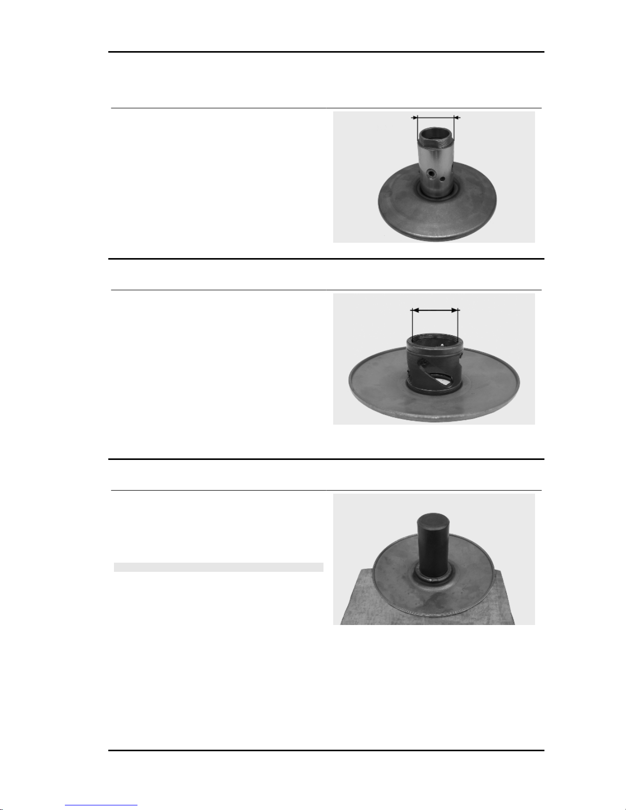
Inspecting the driven fixed half-pulley
- Measure the external diameter of the pulley bushing.
Characteristic
Minimum diameter permitted
Ø 40.96 mm
Standard diameter
Ø 40.965 mm
Inspecting the driven sliding half-pulley
- Remove the 2 inner sealing rings and the two Orings.
- Measure the inside diameter of the mobile halfpulley bushing.
Characteristic
Minimum admissible diameter
Ø 41.08 mm
Standard diameter
Ø 41.035 mm
Refitting the driven half-pulley bearing
- Assemble a new roller case using the specific
punch, fit the bearing with the label facing outward
and insert it completely up to the punch on the halfpulley.
N.B.
REST THE HALF-PULLEY ON A WOOD SURFACE TO
AVOID DAMAGING THE THREADED RINGLET OF THE
DRIVEN PULLEY UPON REMOVING IT.
Specific tooling
020424Y Driven pulley roller casing fitting
punch
Liberty 125 - 200 4tempi Engine
ENG - 71
Page 72
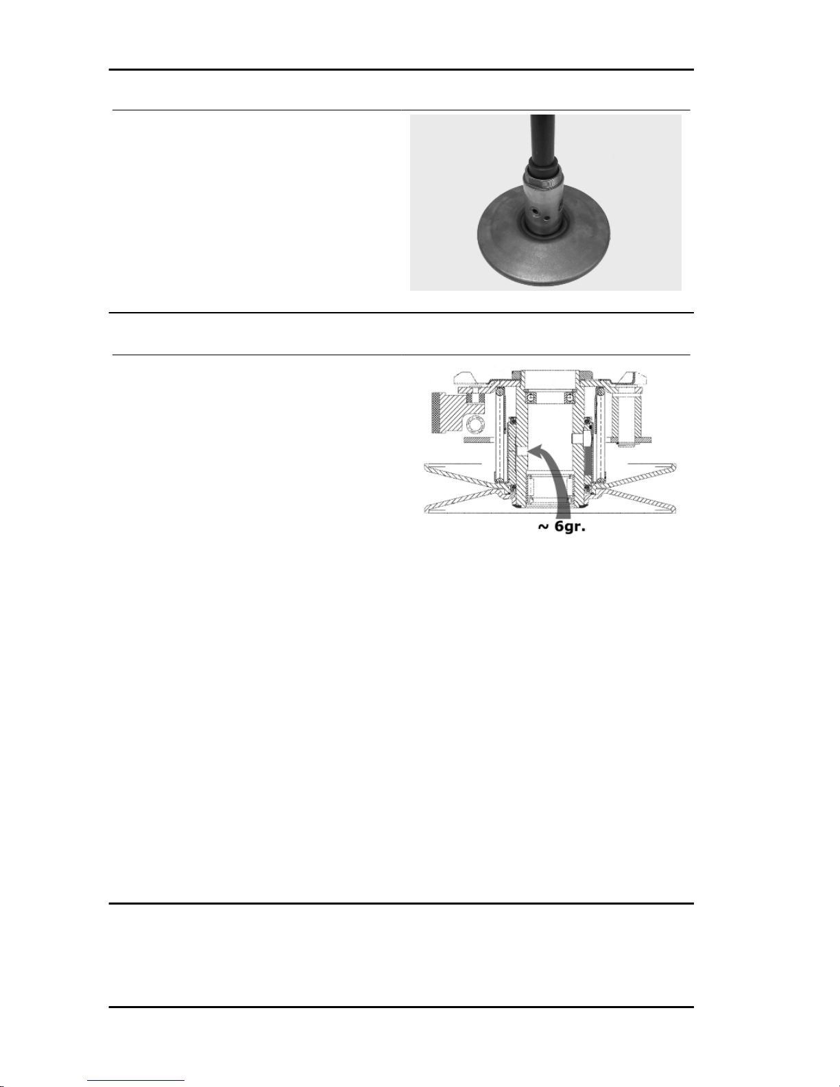
- To assemble the new ball bearing insert it completely down in its housing with the specific punch
and finally assemble the Seeger ring.
Specific tooling
020375Y Adaptor 28 x 30 mm
020376Y Adaptor handle
020439Y 17 mm guide
Refitting the driven pulley
- Check that the faying surfaces between the 2
half-pulleys and the belt do not show any signs of
wear, scoring and grease.
- Insert the new oil seals and O-rings on the movable half-pulley.
- Assemble the half-pulley on the ringlet with the
appropriate protection sheath.
- Make sure the pins and collar are not worn, reassemble the pins and collar.
- Use a greaser with a curved spout to lubricate the
driven pulley unit with around 6 g of grease. This
operation must be done through one of the holes
inside the bushing until grease comes out of the
opposite hole. This operation is necessary to avoid
the presence of grease beyond the O-rings.
Specific tooling
020263Y Driven pulley assembly sheath
Recommended products
AGIP GREASE SM 2 Grease for the tone wheel
revolving ring
Soap-based lithium grease containing NLGI 2 Molybdenum disulphide; ISO-L-XBCHB2, DIN
KF2K-20
Engine Liberty 125 - 200 4tempi
ENG - 72
Page 73

Inspecting the clutch spring
- Measure the unloaded length of the spring of the
movable driven half-pulley.
Characteristic
Standard length:
106 mm
Refitting the clutch
Version 200
- Check the thickness of the clutch mass friction
material.
-The masses must not show traces of lubricants;
otherwise, check the driven pulley unit.
N.B.
UPON RUNNING-IN, THE MASSES MUST EXHIBIT A CEN-
TRAL CONTACT SURFACE AND MUST NOT BE DIFFERENT FROM ONE ANOTHER. VARIOUS CONDITIONS CAN
CAUSE THE CLUTCH TO TEAR.
CAUTION
DO NOT OPEN THE MASSES USING TOOLS SO AS TO
PREVENT A VARIATION IN THE RETURN SPRING LOAD.
Characteristic
Minimum thickness permitted:
1 mm
- Support the driven pulley spring compressor appropriate tool with the control screw in vertical axis.
- Arrange the tool with the medium length pins
screwed in position "C" on the inside.
- Introduce the adapter ring 11 with the chamfering
facing upwards.
- Insert the clutch on the adapter ring.
- Lubricate the end of the spring that abuts against
the servo-system closing collar.
- Insert the spring with its plastic holder in contact
with the clutch.
Liberty 125 - 200 4tempi Engine
ENG - 73
Page 74

- Insert the driving belt into the pulley unit according to their direction of rotation.
- Insert the pulley unit with the belt into the tool.
- Slightly preload the spring.
- Make sure that the clutch is perfectly inserted into
the adapter ring before proceeding to tighten the
clutch nut.
- Place the tool in the clamp with the control screw
on the horizontal axis.
- Fully preload the spring.
- Apply the clutch fixing nut and tighten it to the
prescribed torque using the special 46x55 wrench.
- Loosen the tool clamp and insert the belt according to its direction of rotation.
- Lock the driven pulley again using the specific
tool.
- Preload the clutch return spring with a traction/
rotation combined action and place the belt in the
smaller diameter rolling position.
- Remove the driven pulley /belt unit from the tool.
N.B.
DURING THE SPRING PRELOADING PHASE, BE CARE-
FUL NOT TO DAMAGE THE PLASTIC SPRING STOP AND
THE BUSHING THREADING.
N.B.
FOR DESIGN REASONS, THE NUT IS SLIGHTLY ASYM-
METRIC; THE FLATTEST SURFACE SHOULD BE MOUNTED IN CONTACT WITH THE CLUTCH.
Specific tooling
020444Y Tool for fitting/ removing the driven
pulley clutch
020444Y011 adapter ring
020444Y009 wrench 46 x 55
Locking torques (N*m)
Nut locking clutch unit on pulley 55 ÷ 60 Nm
Version 125
Engine Liberty 125 - 200 4tempi
ENG - 74
Page 75

- Refit the clutch assembly following the fitting operation but in reverse order and using the calliper
spanner. Lock the nut to the specified torque.
CAUTION
USE A BOX-SPANNER WITH SMALL CHAMFER SO AS
NOT TO DAMAGE THE CLUTCH NUT.UPON FITTING THE
CLUTCH ASSEMBLY LOCK NUT, PAY ATTENTION TO
KEEP THE ASSEMBLY IN ITS SEAT UNTIL SOME NUT
THREADS HOLD IT IN PLACE
Locking torques (N*m)
Locking torque 55 ÷ 60 Nm
Refitting the driven pulley
- Reassemble the clutch bell and spacer.
Drive-belt
During the wear checks foreseen in the scheduled
maintenance services at 6,000 km; 18,000 km;
etc., check that the rim bottom of the toothing does
not show signs of incisions or cracking (see figure):
The rim bottom of the tooth must not have incisions
or cracking; if it does, change the belt.
- Check that the driving belt is not damaged.
- Check the width of the belt.
VERSION 125
Specification
Desc./Quantity
Minimum width 21.5 mm
Standard width 22.5 ± 0.2 mm
Liberty 125 - 200 4tempi Engine
ENG - 75
Page 76
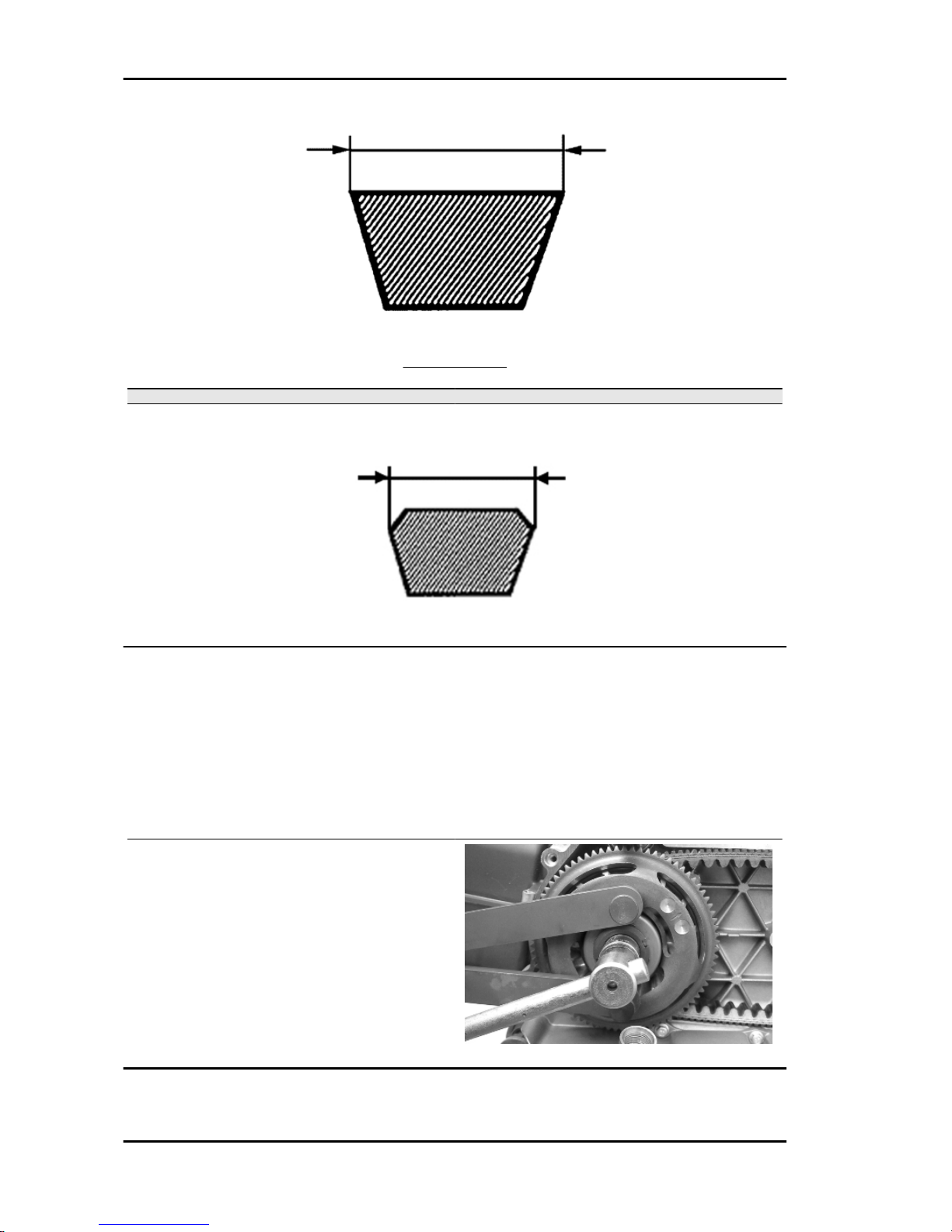
VERSION 200
Specification Desc./Quantity
Minimum width 21±0.2 mm
Standard width 22±0.2 mm
Removing the driving pulley
Driving pulley removal
- With the appropriate tool placed into the internal slots, remove the nut with the built-in Belleville washer.
Appropriate tools:
Specific tooling
020442Y Pulley lock wrench
- Remove the entire start-up crown unit with the
torque limiter.
- Remove the fixed driving half-pulley together with
the O-ring and the steel washer touching the bushing.
Engine Liberty 125 - 200 4tempi
ENG - 76
Page 77

- Lock the driving pulley with the specific tool as
shown in the figure. - Disassemble the central nut
and the Belleville washer, remove the drive and
the 2 washers. - Remove the stationary half pulley
and the steel washer.
Specific tooling
020368Y driving pulley lock wrench
- Remove the belt and slide the movable half-pulley with the relevant bush, taking care of the falling
free assembled rollers.
- Remove the return rollers plate with the relative
guide pads.
Inspecting the rollers case
- Check that the internal bushing is not abnormally worn and measure inner diameter.
N.B.
DO NOT LUBRICATE OR CLEAN THE BUSHING.
BUSHING ROLLER CONTAINER
Specification
Desc./Quantity
Maximum allowable diameter Ø 26.121 mm
Standard diameter Ø 26+0 +0.021 mm
BUSH SLIDE PULLEY
Specification
Desc./Quantity
Minimum diameter permitted Ø 25.950 mm
Standard diameter Ø 26-0.020 -0.041 mm
VARIABLE SPEED ROLLERS
Specification
Desc./Quantity
Minimum diameter permitted Ø 18.5 mm
Standard diameter Ø 26±0.1 mm
Liberty 125 - 200 4tempi Engine
ENG - 77
Page 78

- Check the guide shoes for the variator back-plate
are not worn.
- Check there is no wear in the roller housing, and
the surfaces in contact with the belt on either of the
pulley halves.
- Pre-assemble the movable half-pulley with the
roller contrast plate by placing the rollers as shown
in the figure, that is, during insertion, the closed
side should be on the left side of the pulley thrust.
- Mount the complete bushing unit on the driving
shaft.
- Open the rear pulley and insert the belt observing
the correct direction of rotation.
WARNING
IT IS MOST IMPORTANT THAT WHEN FITTING THE FRONT
PULLEY UNIT, THE BELT IS FREE INSIDE SO AS TO AVOID
A WRONG TIGHTENING OF THE DRIVING HALF-PULLEY.
Engine Liberty 125 - 200 4tempi
ENG - 78
Page 79

Refitting the driving pulley
- Correctly reassemble the previously removed
Bendix back to its position.
- Fit the steel shim washer in contact with the
bushing and the fixed driving pulley together with
the O-ring on the outside of the fan blades.
- Fit the entire start-up crown assembly with the
torque limiter.
- Fit the torque limiter on the crankshaft so as to
guarantee the references on the start-up crown
and the fixed driving half-pulley are aligned. In
case this is not possible, choose the closest position to the references.
- Failure to do this may affect the cooling fan performance
The lock wrench operates on the start-up crown.
- If the torque limiter is worn, the failure can be detected when locking the nut on the crankshaft.
- The torque limiter cannot be serviced.
- In case of failures, replace the start-up crown and
the limiter.
Specific tooling
020442Y Pulley lock wrench
Recommended products
Loctite "Super Rapido" Loctite "Super Rapido"
243
Apply Loctite "Super Rapido" 243 on the threads
and screw the nut with washer to the prescribed
torque.
Locking torques (N*m)
Drive pulley nut 75 ÷ 83
Liberty 125 - 200 4tempi Engine
ENG - 79
Page 80
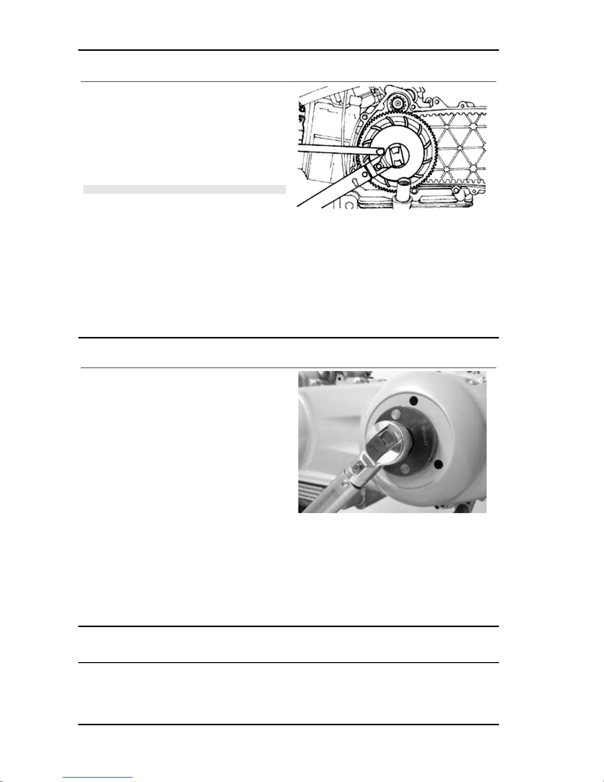
- Reassemble the parts of the unit (internal lining,
fixed half-pulley, external lining, drive and nut),
spread threadlock on the thread and screw the nut
to the prescribed torque.
-Avoid the half-pulley rotation using a calliper
spanner
N.B.
REPLACE THE NUT WITH A NEW ONE AT EVERY REFIT
Specific tooling
020368Y driving pulley lock wrench
Recommended products
Loctite 243 Medium-strength threadlock
Loctite 243 medium-strength threadlock
Locking torques (N*m)
Locking torque 75 ÷ 83
Refitting the transmission cover
- Check that there are 2 centring dowels and that
the sealing gasket for the oil sump on the transmission cover is adequately fitted.
- Replace the cover and tighten the 10 screws to
the specified torque.
- Refit the oil loading cap/bar.
- Refit the steel washer and the driven pulley nut.
- Tighten the nut to the prescribed torque using the
lock wrench and the torque wrench tools.
- Refit the plastic cover.
Specific tooling
020423Y Driven pulley lock wrench
Locking torques (N*m)
Transmission cover screws 11 ÷ 13 Driven pulley shaft nut 54 ÷ 60
End gear
Engine Liberty 125 - 200 4tempi
ENG - 80
Page 81
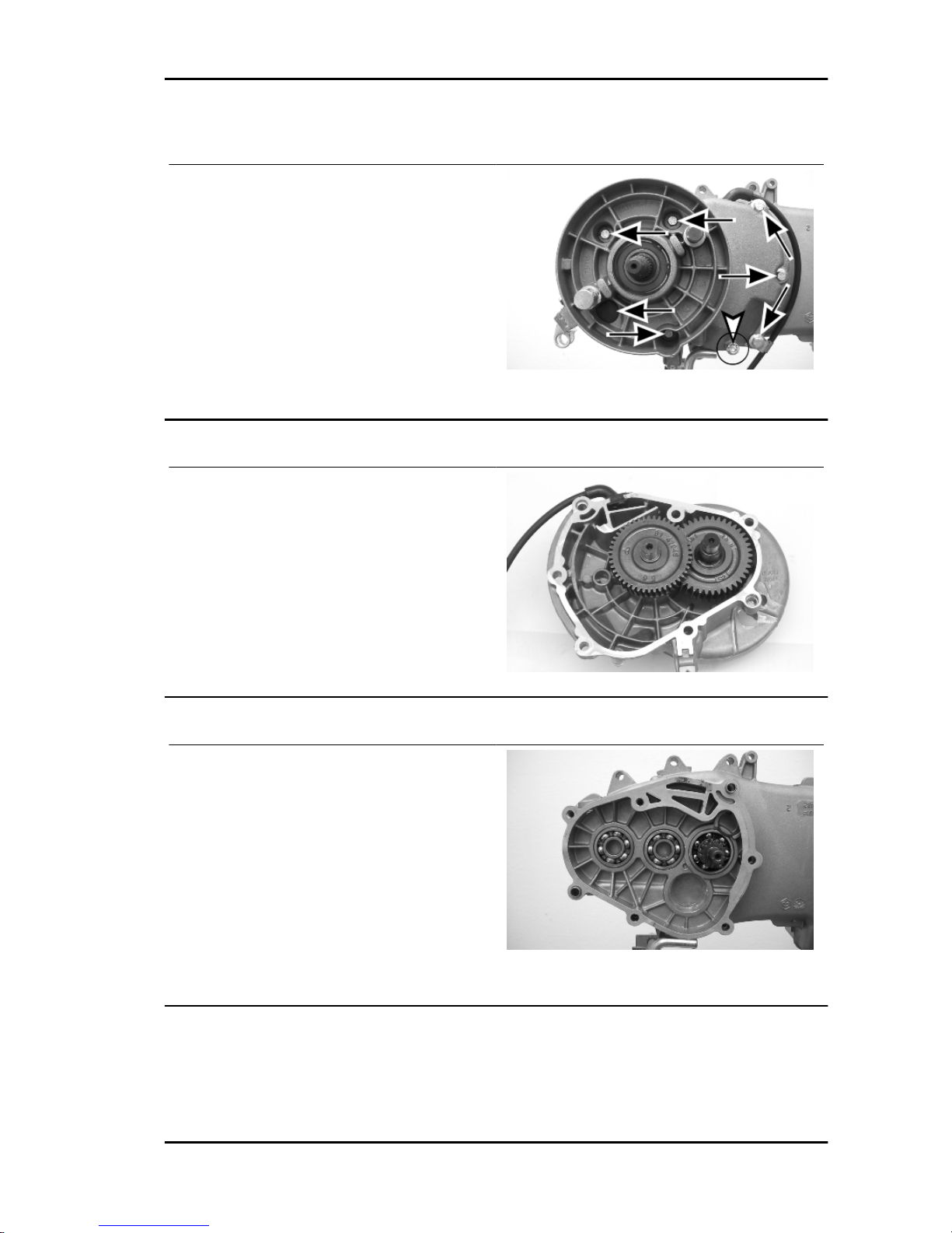
Removing the hub cover
- Empty the rear hub through the oil drainage tap
located inside the hub cover
- Remove the brake shoe and relevant spring
- Remove the 7 flanged screws as shown in the
figure.
- Remove the rubber cover and the brake pad lever
sliding unscrewing the relevant retaining screw to
reach the rear of the cover
- Take off the hub cover and relevant gaskets
Removing the wheel axle
Remove the intermediate gear and the complete
hub cover.
Removing the hub bearings
- Check the state of the bearings being examined
(wear, clearance and noisiness). If faults are detected, do the following.
- Use the specific bearing extractor to remove the
three 15 mm bearings (2 in the crankcase and 1 in
the hub cover).
Specific tooling
001467Y009 Driver for OD 42-mm bearings
001467Y013 Pliers to extract ø 15-mm bearings
Liberty 125 - 200 4tempi Engine
ENG - 81
Page 82

Removing the wheel axle bearings
- Take out the clip on the outside of the gearbox
cover.
- Remove the bearing with the adequate tools adequately supporting the hub cover, as shown in the
figure.
Specific tooling
020376Y Adaptor handle
020364Y 25-mm guide
With the appropriate tools, remove the oil seal as
shown in the figure.
Specific tooling
020376Y Adaptor handle
020359Y 42x47-mm Adaptor
Removing the driven pulley shaft bearing
If it is necessary to remove the driven pulley shaft, from the relevant bearing and oil seal, remove driven
pulley.
- Extract the driven pulley shaft from its bearing.
- Remove the oil guard using a screwdriver, working from inside the bearing and being careful not to
damage the housing, make it come out of the belt transmission side.
- Remove the seeger ring shown in the figure
With the sectional punch, remove the driven pulley
shaft bearing.
Specific tooling
020376Y Adaptor handle
020375Y Adaptor 28 x 30 mm
020363Y 20 mm guide
See also
Removing the driven pulley
Engine Liberty 125 - 200 4tempi
ENG - 82
Page 83
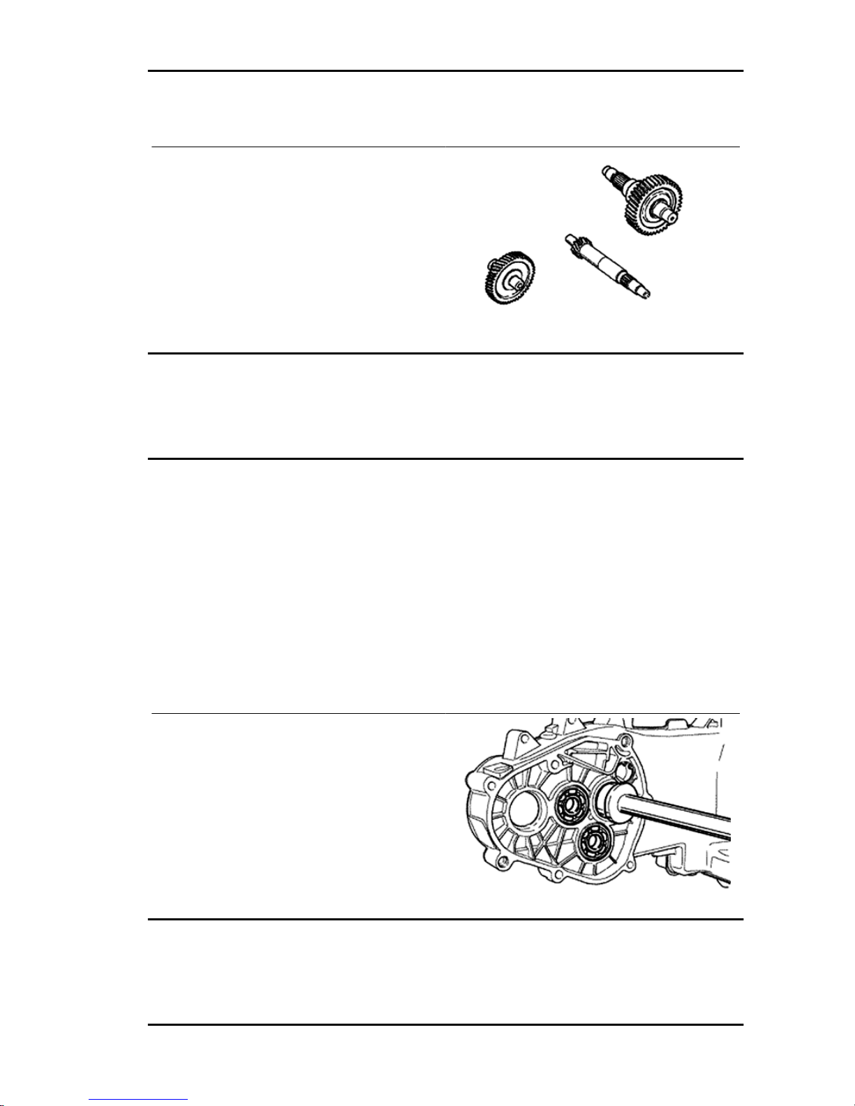
Inspecting the hub shaft
- Check the three shafts for wear or distortion of
the toothed surfaces, the bearing housings, and
the oil seal housings.
- In case of anomalies, replace the damaged components.
Inspecting the hub cover
- Check that the fitting surface is not dented or distorted. - Check the capacity of the bearings and the
brake camshaft. - If faults are found, replace the hub cover.
Refitting the driven pulley shaft bearing
- Heat up the parts using the specific heat gun
Specific tooling
020150Y Air heater support
020151Y Air heater
- Reassemble the driven pulley axle bearing positioning it with ball bearing in view from the inside of
the hub cover using the adequate tools
Specific tooling
020376Y Adaptor handle
- Refit the Seeger ring with the opening facing the
bearing as shown in the figure and fit a new oil
guard flush with the crankcase.
Refitting the wheel axle bearing
- Heat up the parts using the specific heat gun
Specific tooling
Liberty 125 - 200 4tempi Engine
ENG - 83
Page 84
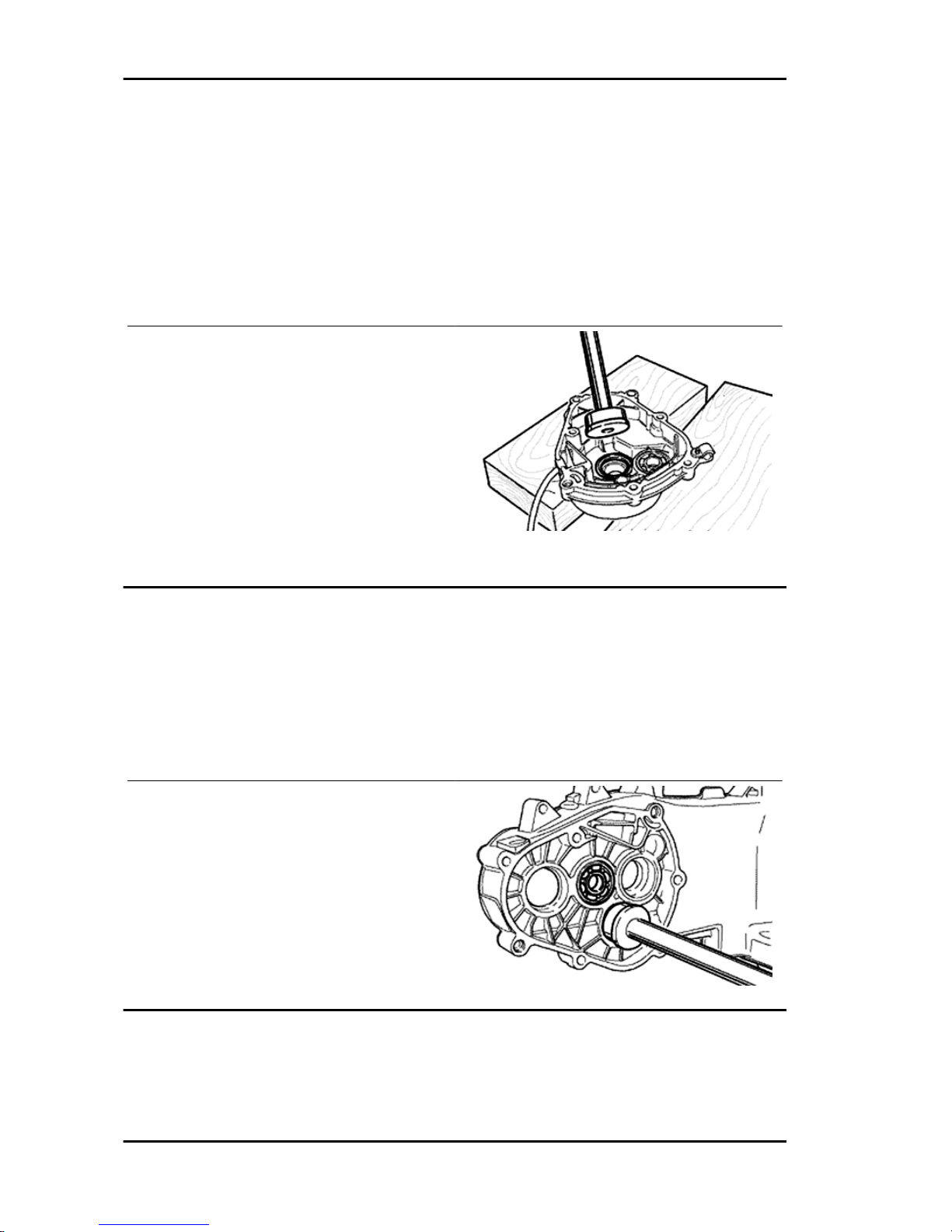
020151Y Air heater
020150Y Air heater support
-The wheel axle bearing on the cover, should be assembled with the specific tools
Specific tooling
020364Y 25-mm guide
020360Y 52x55-mm Adaptor
020376Y Adaptor handle
•
Assemble the Seeger ring.
•
Assemble the oil seal flush with the internal surface as shown in the figure to
the hub using the adequate tools and
with the seal lip towards the inside of
the hub.
Specific tooling
020376Y Adaptor handle
020360Y 52x55-mm Adaptor
Refitting the hub cover bearings
- For the fitting of the hub box bearings the engine crankcase and the cover must be heated with the
specific heat gun.
Specific tooling
020150Y Air heater support
020151Y Air heater
- The three 15 mm bearings must be fitted using
the appropriate tools.
Engine Liberty 125 - 200 4tempi
ENG - 84
Page 85

Refitting the hub bearings
- Insert the cover prepared in the crankcase taking
care of inserting the gear of the pulley shaft on the
intermediary gear.
Refitting the ub cover
- Fit a new gasket together with the centring dowels.
- Fit the gearbox cover, making sure the breather
pipe is in the correct position.
- Screw the 7 screws to the specified torque, positioning the support plate of the pipe in the position shown in the figure.
- Remove the control pin of the shoe taking care
so as the long tooth coincides with the groove on
the control lever.
Locking torques (N*m)
Locking torque 24 ÷ 27
Flywheel cover
Cooling hood
-Remove the housing acting on the 4 retaining
screws.
CAUTION
DURING REMOVAL SLIDE THE HOUSING CONNECTOR
ON THE HOUSING.
Liberty 125 - 200 4tempi Engine
ENG - 85
Page 86
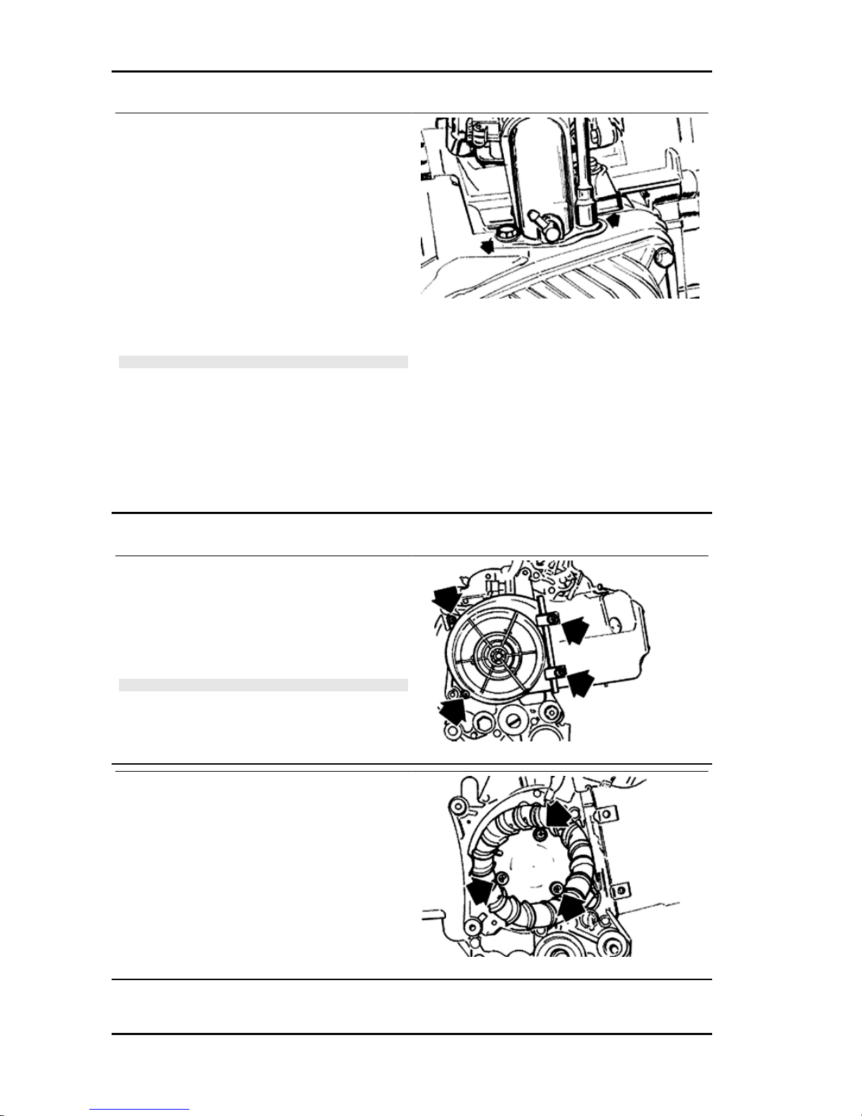
- Loosen the clamp and remove the carburettor
from the manifold.
-Remove the complete manifold acting on the 2
retainers as shown in the figure.
- Remove the 2 self threading screws, left and right
and the lateral base retaining screw on the crankcase base.
- Take off the housings.
- Remove the gasket seal of the housing on the
head.
N.B.
IF THE FLYWHEEL HOUSING IS NOT REMOVED, IT IS AL-
SO NECESSARY TO REMOVE THE TWO KNOB SCREWS.
On the vehicles equipped with the engines mentioned if they are losing a full circle at full gas, we suggest
to intervene on the vacuum socket inserting on the inlet manifold widening the hole from 0.4 mm to 1.5
mm. Remember that such operation must have performed on a disassembled manifold which must be
cleaned afterwards.
Cooling fan
- Refit the parts in reverse order of the removal
operation.
- Make sure that there are spacers with the two
rear retainers of the housing.
- The long spacers should be in a high position.
CAUTION
TAKE CARE TO CORRECTLY POSITION THE FLYWHEEL
CONNECTOR.
- Remove the cooling fan by acting on the three
fixings indicated in the figure.
Engine Liberty 125 - 200 4tempi
ENG - 86
Page 87

Removing the stator
- Remove the electric terminal of the minimum oil
pressure switch.
- Remove the two Pick-Up screws and the one for
the wiring harness bracket as well as the two stator
fixing screws shown in the figure.
- Remove the stator and its wiring.
Refitting the stator
- Refit the stator and flywheel carrying out the removal procedure in reverse, tightening the retainers to the specified torque.
- Place the cable harness as shown in the figure.
N.B.
THE PICK-UP WIRE SHOULD BE POSITIONED BETWEEN
THE UPPER SCREW AND THE REFERENCE PIN AS
SHOWN IN THE DETAIL DRAWING.
Locking torques (N*m)
Stator screw 3 ÷ 4
Flywheel and starting
Liberty 125 - 200 4tempi Engine
ENG - 87
Page 88

Removing the flywheel magneto
- Lock the rotation of the flywheel using the calliper
spanner.
- Remove the nut.
CAUTION
THE USE OF A CALLIPER SPANNER OTHER THAN THE
ONE SUPPLIED COULD DAMAGE THE STATOR COILS
Specific tooling
020565Y Flywheel lock calliper spanner
- Extract the flywheel with the extractor.
Specific tooling
008564Y Flywheel extractor
Inspecting the flywheel components
- Check the integrity of the internal plastic parts of the flywheel and the Pick-Up control plate.
Refitting the flywheel magneto
- Fit the flywheel being careful to insert the key
properly.
- Lock the flywheel nut to the prescribed torque
- Check that the Pick-Up air gap is between 0.34
÷ 0.76 mm.
The air gap cannot be modified when assembling
the Pick-Up.
Different values result from deformations visible
on the Pick-Up support.
N.B.
A VARIATION IN THE AIR GAP DISTANCE MODIFIES THE
IGNITION SYSTEM IDLE SPEED
Locking torques (N*m)
Flywheel nut 52 ÷ 58
Engine Liberty 125 - 200 4tempi
ENG - 88
Page 89
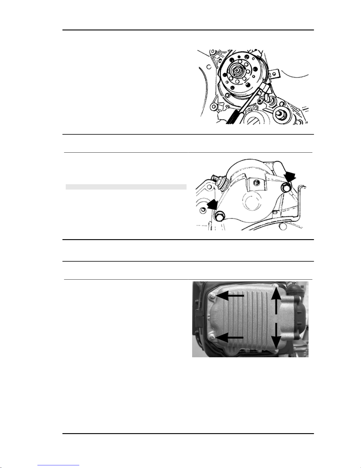
Refitting the starter motor
- Fit a new O-ring on the starter and lubricate it.
- Fit the starter on the crankcase, locking the two
screws to the prescribed torque.
N.B.
REFIT THE REMAINING PARTS AS DESCRIBED IN THE
CYLINDER HEAD, TIMING, LUBRICATION, FLYWHEEL
AND TRANSMISSION CHAPTERS.
Locking torques (N*m)
Starter motor screws 11 ÷ 13
Cylinder assy. and timing system
Removing the timing system drive
- Remove the parts listed below first: transmission
cover, belt driving pulley, oil pump pulley cover and
pinion separator washer.
- Remove the tappet cover.
- Remove the central screw fastener and the automatic valve-lifter retaining cover, as shown in the
figure.
- Remove the return spring of the automatic valve
lifter assembly and the automatic valve lifter assembly and its end of stroke washer.
- Loosen the central screw on the tensioner first.
- Remove the two fixings shown in the figure.
- Remove the tensioner with its gasket.
Liberty 125 - 200 4tempi Engine
ENG - 89
Page 90

- Remove the internal hex screw and the counterweight shown in the figure.
- Remove the camshaft command pulley and its
washer.
- Remove the command sprocket wheel and the
timing chain.
- Remove the screws indicated in the figure, the
spacer bar and the tensioner pad.
The chain tensioning pad must be removed from
the transmission side. As regards the lower chain
guide pad, it may only be removed after the head
has been removed.
N.B.
IT IS ADVISABLE TO MARK THE CHAIN IN ORDER TO EN-
SURE THAT THE INITIAL DIRECTION OF ROTATION IS
MAINTAINED.
See also
Removal
Transmission cover
Removing the driving pulley
Removing the cam shaft
- Remove the two screws and the cam shaft retainer shown in the diagram.
- Remove the cam shaft.
Engine Liberty 125 - 200 4tempi
ENG - 90
Page 91
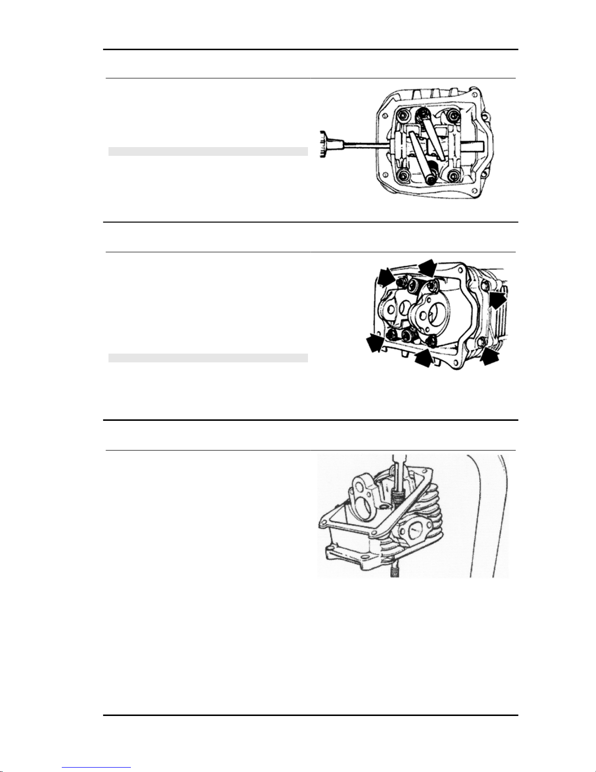
- Remove the pin of the rocking levers from the
flywheel side holes.
- Remove the rocking levers and the elastic washer.
N.B.
MARK THE ROCKING LEVERS ASSEMBLE POSITION, SO
AS TO AVOID THE INVERSION OF INLET WITH THE OUTLET.
Removing the cylinder head
- Remove the spark plug.
- Remove the 2 side fixings shown in the figure.
- Loosen the 4 head-cylinder fastening nuts in two
or three stages and in criss-cross fashion.
- Remove the head, the two centring dowels and
the gasket.
N.B.
IN NEEDED, THE HEAD MAY BE REMOVED WITH THE
CAMSHAFT, ROCKING LEVER PINS AND FIXING BRACKET. THE HEAD CAN ALSO BE REMOVED WITHOUT REMOVING THE CHAIN AND THE DRIVING SHAFT CHAIN
TIGHTENER.
Removing the valves
- Using the specific tool fitted with the element
shown in the figure, remove the cotters, the plates
and the spring between the valves.
Specific tooling
020382Y Valve cotters equipped with part 012
removal tool
020382Y011 adapter for valve removal tool
Liberty 125 - 200 4tempi Engine
ENG - 91
Page 92

- Remove the oil seals with the appropriate tool.
- Remove the lower spring supports.
Specific tooling
020431Y Valve oil seal extractor
Removing the cylinder - piston assy.
- Remove the chain guide pad.
- Remove the cylinder base gasket.
CAUTION
TO AVOID DAMAGING THE PISTON, SUPPORT IT WHILE
REMOVING THE CYLINDER.
- Remove the two stop rings, the wrist pin and the
piston.
- Remove the 3 piston rings from the piston.
N.B.
BE CAREFUL NOT TO DAMAGE THE PISTON RINGS DUR-
ING REMOVAL.
Inspecting the small end
- Measure the internal diameter of the small end
using an internal micrometer.
N.B.
IF THE DIAMETER OF THE ROD SMALL END EXCEEDS
THE MAXIMUM DIAMETER ALLOWED, SHOWS SIGNS OF
WEAR OR OVERHEATING REPLACE THE CRANKSHAFT
AS DESCRIBED IN THE "CRANKCASE AND CRANKSHAFT" CHAPTER".
Characteristic
Rod small end check-up: Maximum diameter
15.030 mm
Engine Liberty 125 - 200 4tempi
ENG - 92
Page 93

Rod small end check-up: Standard diameter
15+0.015+0.025 mm
Inspecting the wrist pin
- Check the outer diameter of the gudgeon pin.
Characteristic
Standard pin diameter
14.996 ÷ 15 mm
Minimum diameter permitted
Ø 14.994 mm
- Calculate the piston pin coupling clearance.
N.B.
THE PIN HOUSINGS HAVE 2 LUBRICATION CHANNELS.
FOR THIS REASON MEASUREMENT OF THE DIAMETER
MUST BE CARRIED OUT ACCORDING TO THE AXIS OF
THE PISTON.
Characteristic
Piston pin bore - standard diameter
Ø 15+0.001 +0.006
- Measure the outside diameter of the piston, perpendicular to the gudgeon pin axis.
- Measure 36.5 mm from the piston crown's shown
in the figure.
N.B.
THE PIN HOUSINGS HAVE 2 LUBRICATION CHANNELS.
FOR THIS REASON MEASUREMENT OF THE DIAMETER
MUST BE CARRIED OUT ACCORDING TO THE AXIS OF
THE PISTON.
- Using a bore meter, measure the inner cylinder
diameter at three different points according to the
directions shown in the figure.
- Check that the coupling surface with the head is
not worn or misshapen.
- Pistons and cylinders are classified into categories based on their diameter. The coupling is carried out in pairs (A-A, B-B, C-C, D-D).
Characteristic
Liberty 125 - 200 4tempi Engine
ENG - 93
Page 94

Maximum allowable run-out:
0.05 mm
- The cylinder rectifying operation should be carried out with a surfacing that respects the original
angle.
- The cylinder surface roughness should be 0.9
micron.
- This is indispensable for a good seating of the
sealing rings, which in turn minimises oil consumption and guarantees optimum performance.
- The pistons are oversized due to cylinder rectification and are subdivided into three categories
1st, 2nd, 3rd with 0.2-0.4-0.6 mm oversize. They
are also classified into 4 categories A-A, B-B, CC, D-D.
Inspecting the piston
- Carefully clean the seal housings.
- Measure the coupling clearance between the seal rings and the grooves using suitable sensors, as
shown in the diagram.
- If the clearance is greater than that indicated in the table, replace the piston.
STANDARD COUPLING CLEARANCE
Name
Description Dimensions Initials Quantity
Top piston ring 0.025 ÷ 0.070
Middle piston ring 0.015 ÷ 0.060
oil scraper 0.015 ÷ 0.060
MAXIMUM ADMITTED CLEARANCE AFTER USE
Name
Description Dimensions Initials Quantity
Top piston ring 0.080 mm
Middle piston ring 0.070 mm
oil scraper 0.070 mm
Engine Liberty 125 - 200 4tempi
ENG - 94
Page 95

Inspecting the piston rings
- Alternately insert the three sealing rings into the cylinder, in the area where it retains its original diameter. Using the piston, insert the rings perpendicularly to the cylinder axis.
- Measure the opening, see figure, of the sealing rings using a thickness gauge.
- If any measurements are greater than specified, replace the piston rings.
N.B.
BEFORE REPLACING ONLY THE PISTON RINGS, ENSURE THAT THE CLEARANCE BETWEEN
THE PISTON RINGS AND THE PISTON RING GROOVES, AND BETWEEN THE PISTON AND THE
CYLINDER, IS AS SPECIFIED. IN ANY CASE, NEW PISTON RINGS USED IN COMBINATION WITH
A USED CYLINDER MAY HAVE DIFFERENT BEDDING CONDITIONS THAN THE STANDARD.
SEALING RINGS (125)
Name Description Dimensions Initials Quantity
Compression ring 57 x 1 A 0.15 ÷ 0.30
Oil scraper ring 57x1 A 0.10 ÷ 0.30
Oil scraper ring 57x2.5 A 0.10 ÷ 0.35
Compression ring 1st
oversize
57.2 x 1 A 0.15 ÷ 0.30
Oil scraper ring 1st
oversize
57.2x1 A 0.10 ÷ 0.30
Oil scraper ring 1st
oversize
57.2x2.5 A 0.10 ÷ 0.35
Compression ring 2nd
oversize
57.4x1 A 0.15 ÷ 0.30
Oil scraper ring 2nd
oversize
57.4x1 A 0.10 ÷ 0.30
Oil scraper ring 2nd
oversize
57.4x2.5 A 0.10 ÷ 0.35
Compression ring 3rd
oversize
57.6x1 A 0.15 ÷ 0.30
Oil scraper ring 3rd
oversize
57.6x1 A 0.10 ÷ 0.30
Oil scraper ring 3rd
oversize
57.6x2.5 A 0.10 ÷ 0.35
Maximum clearance after use: 1 mm
MAX. VALUE (125)
Name
Description Dimensions Initials Quantity
Top piston ring 0,40
Middle piston ring 0,40
Oil scraper 0,45
SEALING RINGS (200)
Name
Description Dimensions Initials Quantity
Compression ring 72x1.5 A 0.15 ÷ 0.30
Oil scraper ring 72x1 A 0.20 ÷ 0.40
Oil scraper ring 72x2.5 A 0.20 ÷ 0.40
MAX. VALUE (200)
Name
Description Dimensions Initials Quantity
Top piston ring 0,40
Middle piston ring 0,50
oil scraper 0,50
Liberty 125 - 200 4tempi Engine
ENG - 95
Page 96

Removing the piston
- Install piston and wrist pin onto the connecting
rod, aligning the piston arrow the arrow facing towards the exhaust.
- Fit the pin stop ring onto the appropriate tool.
Specific tooling
020430Y Pin lock fitting tool
- With the opening in position indicated on the tool,
take stop ring in the closed position using the
punch.
- Fit the wrist pin stop using the plug as shown in
the figure
N.B.
THE TOOL FOR INSTALLING THE STOP RINGS MUST BE
USED MANUALLY.
CAUTION
USING A HAMMER TO POSITION THE RINGS CAN DAM-
AGE THE LOCKING HOUSING.
Choosing the gasket
- Provisionally fit the piston into the cylinder, without any base gasket.
- Assemble a dial gauge on the specific tool
- Set the dial gauge to zero at a contrast plane with an average precharge, for example 5 mm. Keeping
the zero setting position, fit the tool on the cylinder and lock it with 2 nuts, as shown in the figure.
- Rotate the crankshaft until TDC (the inverted point of the dial gauge rotation)
- Calculate the difference between the two measurements: use the chart below to identify the thickness
of the cylinder base gasket to be used for refitting. The proper identification of the cylinder base gasket
thickness allows maintaining the correct compression ratio.
- Remove the special tool and the cylinder.
Engine Liberty 125 - 200 4tempi
ENG - 96
Page 97

Characteristic
Standard compression ratio
10.6 ± 0.5
CYLINDER BASE GASKET THICKNESS
Specification Desc./Quantity
Value measured 1 ÷ 1.1
Thickness 0.8 ± 0.05
Value measured 1.1 ÷ 1.3
Thickness 0.6 ± 0.05
Value measured 1.3 ÷ 1.4
Thickness 0.4 ± 0.05
Liberty 125 - 200 4tempi Engine
ENG - 97
Page 98
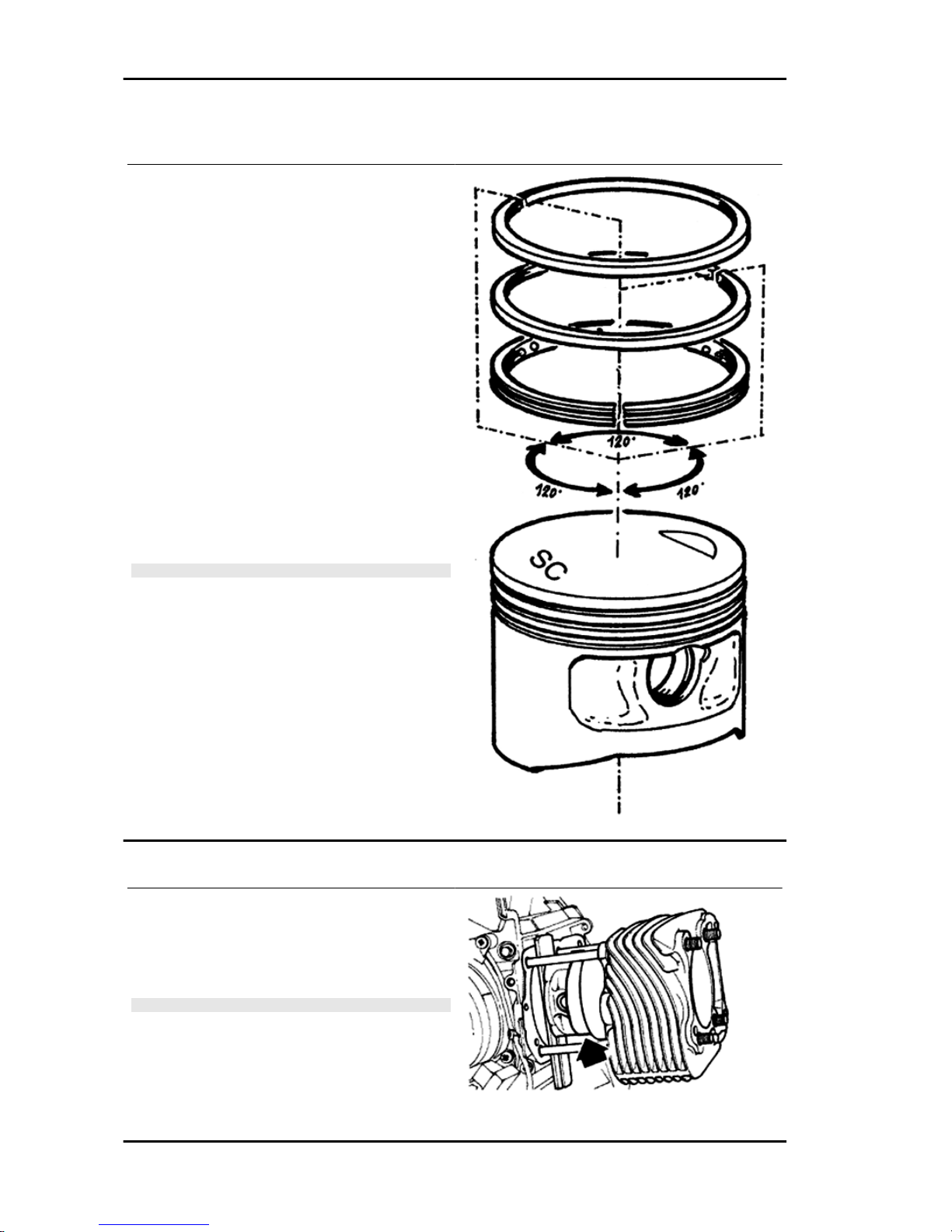
Refitting the piston rings
- Place the oil scraper spring on the piston.
- Refit the oil scraper ring with the join of spring
ends on the opposite side from the ring gap and
the word 'TOP' towards the crown of the piston.
The tapered side of the middle piston ring should
always be facing away from the crown of the piston.
- Fit the middle piston ring with the identification
letter facing the crown of the piston. In any case,
the step must be facing opposite the piston top.
- Fit the top piston ring with the word 'top' or the
reference mark facing the crown of the piston.
- Offset the piston ring gaps on the three rings by
120° to each other as shown in the figure.
- Lubricate the components with engine oil.
N.B.
SO AS TO OBTAIN THE BEST CONFIGURATION THE 2
SEALING RINGS ARE MADE WITH A CONTACT CONICAL
CYLINDER SECTION.
Refitting the cylinder
- Insert the cylinder base gasket with the thickness
determined above.
- Using the fork support and the piston ring retaining band, refit the cylinder as shown in the figure.
N.B.
BEFORE FITTING THE CYLINDER, CAREFULLY BLOW
OUT THE LUBRICATION DUCT AND OIL THE CYLINDER
BARREL.
Specific tooling
020426Y Piston fitting fork
Engine Liberty 125 - 200 4tempi
ENG - 98
Page 99
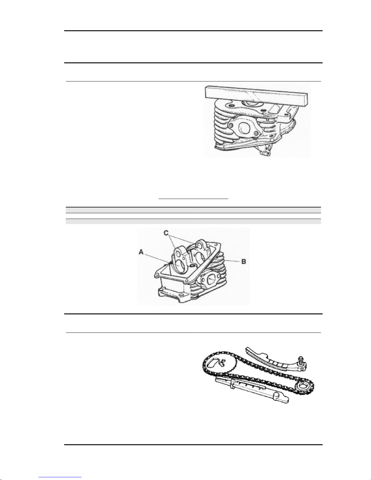
020427Y Piston fitting band
Inspecting the cylinder head
- Using a trued bar check that the cylinder head
surface is not worn or distorted.
- Check that the camshaft and rocking lever pin
bearings show no signs of wear.
- Check that the cylinder head cover surface, the
intake manifold and the exhaust manifold are not
worn.
Characteristic
Maximum admitted unevenness: Head check
0.05 mm
STANDARD DIAMETER
Specification Desc./Quantity
Standard diameter A Ø 32.5 ÷ 32.525
Standard diameter B Ø 20 ÷ 20.021
Standard diameter C Ø 12 ÷ 12.018
Inspecting the timing system components
- Check that the guide shoe and the tensioner shoe
are not worn out.
- Ensure that the camshaft drive pulley, the chain
assembly and the sprocket wheel are not worn.
- If sings of wear are found, replace the parts. if the
chain, pinion or pulley are worn, replace the whole
assembly.
Liberty 125 - 200 4tempi Engine
ENG - 99
Page 100
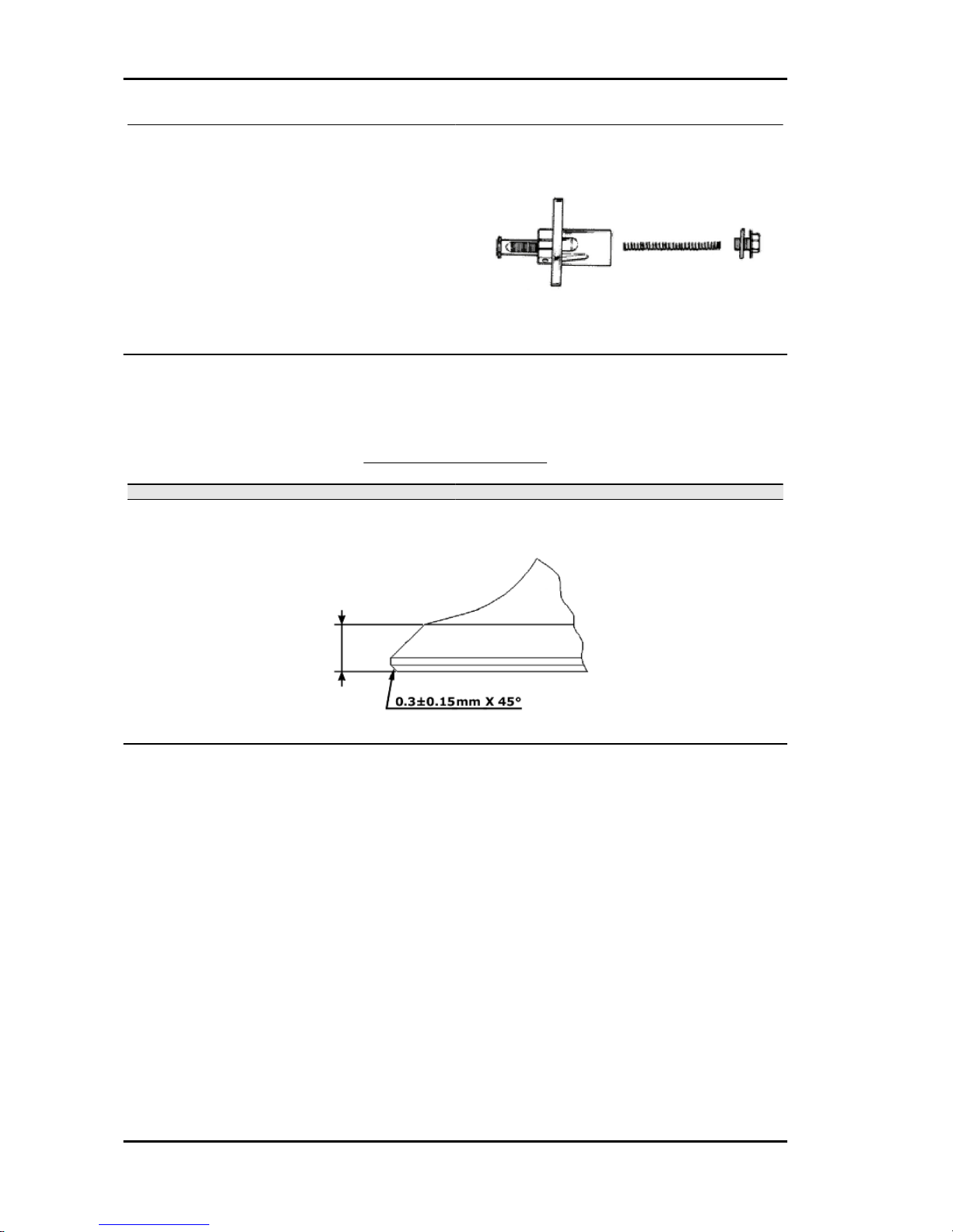
- Remove the central screw and the tensioner
spring. Check that the one-way mechanism is not
worn.
- Check the condition of the tensioner spring.
- If examples of wear are found, replace the whole
assembly.
Inspecting the valve sealings
- Measure the width of the sealing surface on the valve seats.
VALVE SEAL SURFACE
Specification Desc./Quantity
Inlet valve - seal surface 2.4 ÷ 2.8 mm
Outlet valve - seal surface 2.2 ÷ 2.6 mm
Inspecting the valve housings
- Remove any carbon formation from the valve guides.
- Measure the inside diameter of each valve guide.
- Take the measurement at three different heights in the rocker arm push direction.
Characteristic
Standard drainage guide diameter
5.012 mm
Standard inlet guide diameter
5.012 mm
Engine Liberty 125 - 200 4tempi
ENG - 100
 Loading...