

Philips FWC-185 Service Manual
Mini System
FWC185
For /77/79/98 version
TABLE OF CONTENTS
Handling chip components ............................................................ 1-1
Service tools .................................................................................. 1-1
Leadfree and safety information ................................................... 1-2
Technical specification .................................................................. 2-1
Service measurement setup ......................................................... 2-2
Connections and controls ..................................................... 3-1...3-3
Disassembly diagram ............................................................ 4-1...4-3
Wiring diagram .............................................................................. 5-1
Display board
circuit diagram .......................................................................... 6-1
layout diagram .......................................................................... 6-2
CD board
circuit diagram. ......................................................................... 7-1
layout diagram .......................................................................... 7-2
Main board
circuit diagram .......................................................................... 8-1
layout diagram .......................................................................... 8-2
Power board
circuit diagram .......................................................................... 9-1
layout diagram .......................................................................... 9-1
Exploded view diagram ................................................................. 10-1
Mechanical partslist ....................................................................... 10-2
Electrical partslist ..............................................................11-1...11-2
©
Copyright 2006 Philips Consumer Electronics B.V. Eindhoven, The Netherlands
All rights reserved. No part of this publication may be reproduced, stored in a retrieval
system or transmitted, in any form or by any means, electronic, mechanical, photocopying,
or otherwise without the prior permission of Philips.
Published by YB 0628 Service Audio Printed in The Netherlands Subject to modification
Version 1.0
© 3141 785 31230

HANDLING CHIP COMPONENTS
1 - 1
1 - 2

SPECIFICATIONS
2 - 1
GENERAL:
Mains voltage : 240V
Mains frequency : 50 Hz
Power consumption : < 90W max.
< 8 W at standby
Clock accuracy : 4 seconds per day
Dimension center unit : 265 x 295 x 320 mm
TUNER:
FM
Tuning range : 87.5 – 108 MHz
IF Frequency : 10.7 MHz ± 20kHz
Aerial input : wire
Sensitivity at 26sb S/N : < 22 dB
Selectivity at 600 kHz
Bandwidth : > 45 dB
IF rejection : > 50 dB
Image rejection : > 20 dB
Distortion : < 7 %
Crosstalk : > 22 dB
MW
Tuning range : 531 – 1602kHz
Grid : 9 kHz
IF Frequency : 465 kHz ± 5 kHz
Aerial input : Bar antenna
Sensitivity at 26sb S/N : < 4.4 mV/M
Selectivity at 18 kHz
Bandwidth : > 22 dB
IF rejection : > 45 dB
Image rejection : > 28 dB
Distortion : < 5%
AMPLIFIER:
Output power : 2 x 15 W RMS
Speaker impedance : 3 ohm
Frequency response
Within ± 3dB : 60Hz – 16 kHz
Dynamic Bass Boost ON : 8dB ± 3dB at 60Hz
CASSETTE RECORDER:
Number of tracks : 2 x 2 stereo
Tape speed : 4.76 cm/sec +2.5/-1.5%
Wow and flutter : < 0.35% DIN
Fast-wind/rewind time : < 130 sec. With C-60
Bias frequency : 75 ± 10 kHz
R/P frequency response : 125 – 8 kHz (8 dB)
Signal to noise radio : > 42 dB with type 1 tape
COMPACT DISC:
Number of programming track : 30
Frequency response
Within ± 3 dB : 30 Hz – 16 kHz
Signal/Noise ratio : 76 dB/A-weighted
Distortion at 1 kHz : < 3%
Channel separation at 1 kHz : > 25 dB

SERVICE MEASUREMENT
2 - 2
Tuner FW
RF Generator
e.g. PM5326
DUT
Bandpass
250Hz-15kHz
e.g. 7122 707 48001
LF Voltmeter
e.g. PM2534
½
Ri=50
S/N and distortion meter
e.g. Sound Technology ST1700B
Use a bandpass filter to eliminate hum (50Hz, 100Hz) and disturbance from the pilottone (19kHz, 38kHz).
Tuner AM (MW,LW)
RF Generator
e.g. PM5326
½
Ri=50
DUT
Frame aerial
e.g. 7122 707 89001
Bandpass
250Hz-15kHz
e.g. 7122 707 48001
LF Voltmeter
e.g. PM2534
S/N and distortion meter
e.g. Sound Technology ST1700B
To avoid atmospheric interference all AM-measurements have to be carried out in a Faraday«s cage.
Use a bandpass filter (or at least a high pass filter with 250kHz) to eliminate hum (50Hz, 100Hz).
CD RECORDER
Use Audio Signal Disc SBC429 4822 397 30184
(replaces test disc 3)
DUT
L
R
S/N and distortion meter
e.g. Sound Technology ST1700B
LEVEL METER
e.g. Sennheiser UPM550
with FF-filter
Use Universal Test Cassette Fe SBC420 4822 397 30071
LF Generator
e.g. PM5110
DUT
½
Ri=50
L
R
S/N and distortion meter
e.g. Sound Technology ST1700B
LEVEL METER
e.g. Sennheiser UPM550
with FF-filter
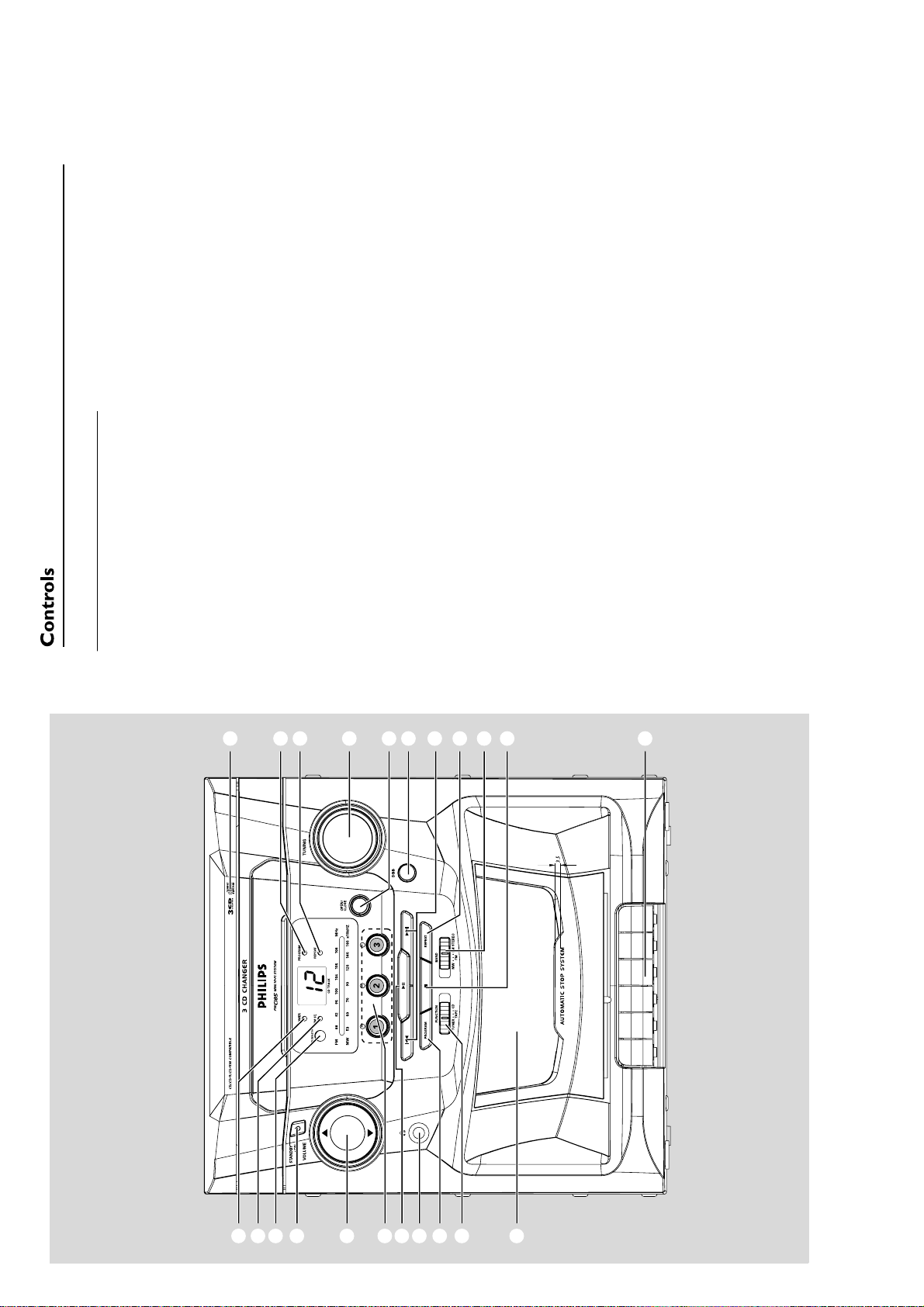
CONNECTION AND CONTROLS
3 - 1
, 4
3
@ Ta pe deck
# FUNCTION: TUNER, TAPE, CD
– selects CD, tape or radio source of sound
Controls on the system
Disc trays
– programs tracks and reviews the program
$ PROGRAM
PROGRAM indicator
REPEAT indicator
% n
TUNING rotary
tunes to radio stations
1
Helpful hints:
before you plug in the headphones.
– Connecting headphones will switch off the
– Adjust the volume to a moderate level
3.5 mm headphone socket
–
OPEN/CLOSE
press to open/close the disc tray
DBB
2
3
6
selects a disc tray for playback*V
–
REPEAT
7
OLUME
– adjusts the volume level
BAND (MW•FM•FM STEREO)
9
8
speakers.
starts or pauses CD playback
^ ÉÅ
–
& DISC: 1/ 2/ 3
skips or searches CD tracks backwards/
4 / ¢
forwards
5
turns the bass enhancement on/off
4
POWER
mode.)REMOTE SENSOR
(
– switches the system on or to standby
STOPÇ
stops CD playback;
0
control towards this sensor.
– sensor for the infrared remote control
Helpful hints: Always point the remote
ases a CD program
r
Ta pe deck keys
£ .................... starts playback
RECORD .. star ts recording
!
¡ FM ST. indicator
™ Power indicator
stops playback;
à /á ............ fast rewinds/winds a tape
70 ....................
recording
............................. opens the tape holder
Å ...................... interrupts playback or
™¡)
(
*
&
^
%
$
#
@
CONNECTION AND CONTROLS
(left)
Speaker
3 - 2
power cord
AC
2
FM wire antenna
Speaker
(right)
Black
-
Red
1
+
Press the clip of the black terminal and fully
insert the stripped portion of the black (or
unmarked) speaker cable into the socket, then
Warning:
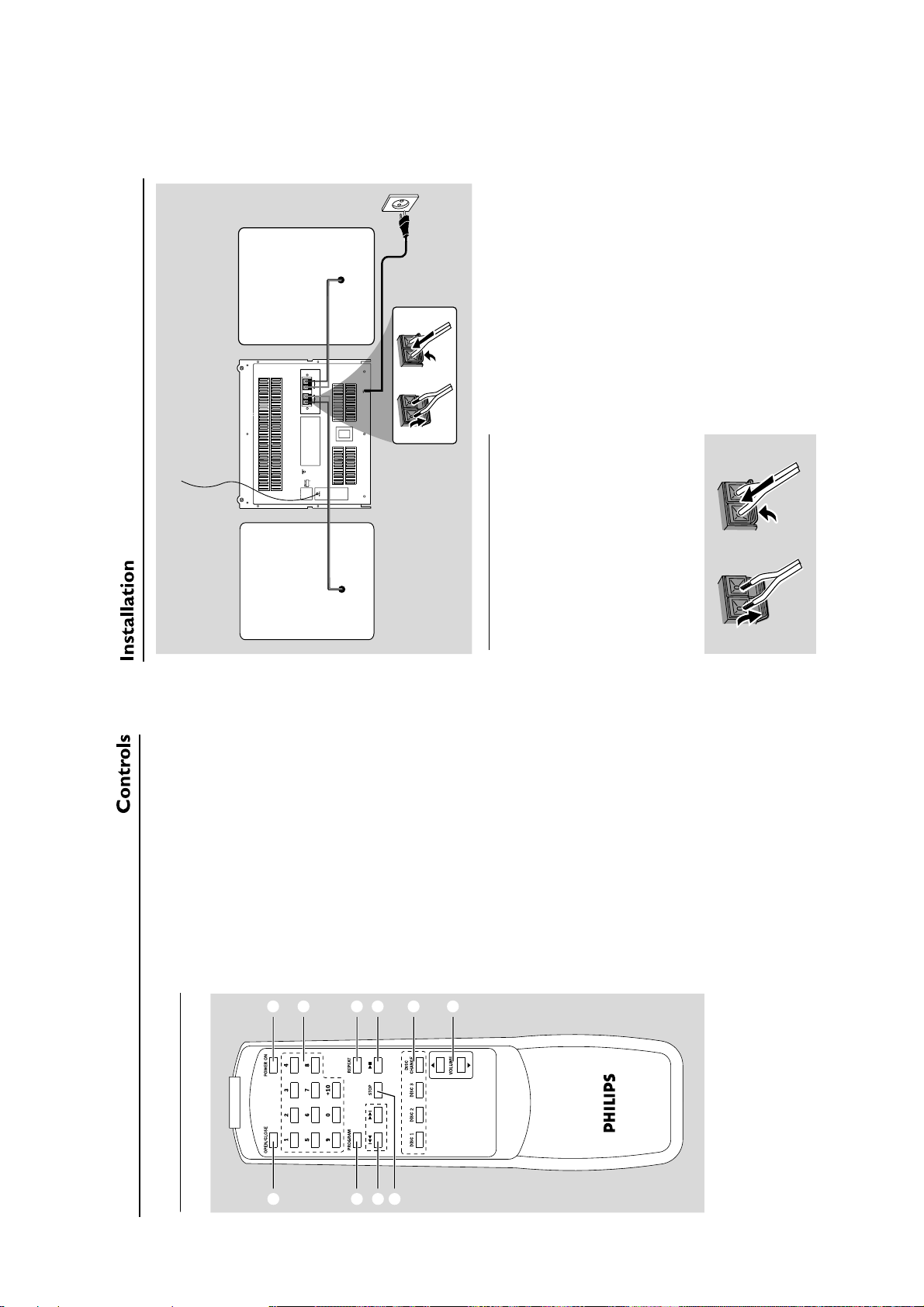
Rear connections
release the clip.
B FM antenna
Never make or change connections with
the power supply switched on.
ay as possible from the TV, VCR or other
adiation sources).
r
in different positions for optimal reception (as far
aw
Fix the antenna’s end to the wall.
1 Extend the wire antenna and move the antenna
Speakers connection
Use the supplied speakers only. Using other
2
and black
”
+
and left speaker to
R”
speakers can damage the set or the sound
”, red (labelled red) wire to “
quality will be negatively affected.
Connect the speaker wires to the SPEAKERS
terminals, right speaker to “
“L
”.
Black
-
Red
(labelled black) wire to “-
+
the stripped portion of the coloured (or
marked) speaker cable into the socket, then
Press the clip of the red terminal and fully insert
switches the system on or to standby
mode2DIGITS 0 - +10
1 POWER ON
–
Remote control
– CD: selects a track number
3 REPEAT
– selects repeat modes
4ÉÅ– starts or pauses CD playback
102
DISC 1/DISC 2/DISC 3
selects a disc tray for playback
5 DISC
–
3
4
5
987
4
,
3
OLUME
DISC CHANGE
V
– changes disc trays
– adjusts the volume level
6
6
7 STOP
stops CD playback
–
skips or searches CD tracks backwards/
forwards
–
– erase a CD program
8 4 / ¢
programs tracks and reviews the program
9 PROGRAM
–
press to open/closes the disc tray
0 OPEN/CLOSE
–
 Loading...