

Philips FW910SR/P22, FW910R/22 User Manual
Mini HiFi System
FW 910SR
1

Important notes for users in the U.K.
Mains plug
FrançaisEnglish
This apparatus is fitted with an approved 13 Amp plug. To change a fuse in this
type of plug proceed as follows:
1 Remove fuse cover and fuse.
Español
2 Fix new fuse which should be a BS1362 5 Amp, A.S.T.A. or BSI approved type.
3 Refit the fuse cover.
If the fitted plug is not suitable for your socket outlets, it should be cut off and an
Deutsch ∂ППЛУИО¿PortuguêsSuomiDanskSvenskaItalianoNederlands
appropriate plug fitted in its place.
If the mains plug contains a fuse, this should have a value of 5 Amp. If a plug
without a fuse is used, the fuse at the distribution board should not be greater
than 5 Amp.
Note: The severed plug must be disposed of to avoid a possible shock hazard
should it be inserted into a 13 Amp socket elsewhere.
How to connect a plug
The wires in the mains lead are coloured with the following code: blue = neutral
(N), brown = live (L).
As these colours may not correspond with the colour markings identifying the
terminals in your plug, proceed as follows:
• Connect the blue wire to the terminal marked N or coloured black.
• Connect the brown wire to the terminal marked L or coloured red.
• Do not connect either wire to the earth terminal in the plug, marked E (or e) or
coloured green (or green and yellow).
Before replacing the plug cover, make certain that the cord grip is clamped over
the sheath of the lead - not simply over the two wires.
Copyright in the U.K.
Recording and playback of material may require consent. See Copyright Act 1956
and The Performer’s Protection Acts 1958 to 1972.
Italia
DICHIARAZIONE DI CONFORMITA’
Si dichiara che l’apparecchio FW910SR Philips
risponde alle prescrizioni dell’art. 2 comma 1 del
D.M. 28 Agosto 1995
n. 548.
Fatto a Eindhoven , il 23/08/1999
Philips Consumer Electronics
5616 JB Eindhoven, The Netherlands
Philips, Glaslaan 2
Norge
Typeskilt finnes på apparatens underside.
Observer:
Den innebygde netdelen er derfor ikke frakoplet
nettet så lenge apparatet er tilsluttet
nettkontakten.
For å redusere faren for brann eller elektrisk
støt, skal apparatet ikke utsettes for regn eller
fuktighet.
Nettbryteren er sekundert innkoplet.
2

INDEX
CLASS 1
LASER PRODUCT
English .....................................5
Français .................................32
Español ..................................63
Deutsch ..................................93
Nederlands..........................123
Italiano .................................153
Svenska ...............................184
Dansk ...................................213
Suomi ...................................243
Português ............................273
∂ППЛУИО¿
............................ 303
EnglishFrançais
Español
NederlandsItalianoSvenskaDanskSuomiPortuguês∂ППЛУИО¿ Deutsch
3

English
4

CONTENTS GENERAL INFORMATION SAFETY INFORMATION
General Information .......................... 5
Safety Information ............................. 5
Preparation ................................... 6 - 7
Controls ....................................... 8 - 10
Operating The System ............ 11 - 12
CD ............................................... 13 - 15
CD Recorder.............................. 15 - 21
Tuner .......................................... 22 - 24
Tape............................................ 24 - 25
Aux ..................................................... 25
Recording .................................. 26 - 27
Clock .................................................. 27
Timer .......................................... 27 - 28
Maintenance .................................... 28
Specifications .................................. 29
Troubleshooting ....................... 30 - 31
General Information
• The type plate (which contains the
serial number) is located at the rear
of the system.
• Recording is permissible if
copyright or other rights of third
parties are not infringed.
• This product complies with the
radio interference requirements of
the European Community.
Environmental Information
All unnecessary packaging material has
been omitted. We have done our utmost to
make the packaging easily separable into
three mono-materials: cardboard (box),
polystyrene foam (buffer) and polythene
(bags, protective foam sheet).
Your system consists of materials which
can be recycled and reused if disassembled
by a specialized company. Please observe
the local regulations regarding the disposal
of packaging materials, exhausted
batteries and old equipment.
Accessories
– Remote control
– Batteries (2 x AA size) for remote control
– AM loop antenna
– FM wire antenna
– AC power cord
– CD Recorder
(Supplied)
Safety Information
• Before operating the system, check that
the operating voltage indicated on the
typeplate (or the voltage indication
beside the voltage selector) of your
system is identical with the voltage of
your local power supply. If not, please
consult your dealer. The type plate is
located at the rear of your system.
• When the system is switched on, do not
move it around.
• Place the system on a solid base (e.g. a
cabinet).
• Place the system in a location with
adequate ventilation to prevent internal
heat build-up in your system.
• Do not expose the system to excessive
moisture, rain, sand or heat sources.
• Under no circumstances should you
repair the system yourself, as this will
invalidate the warranty!
• If the system is brought directly from a
cold to a warm location, or is placed in a
very damp room, moisture may
condense on the lens of the CD unit
inside the system. Should this occur, the
CD player will not operate normally.
Leave the power on for about one hour
with no disc in the system until normal
playback is possible.
• Electrostatic discharge may cause
unexpected problems. See whether
these problems disappear if you unplug
the AC power cord and plug it in again
after a few seconds.
• To disconnect the system from the
power supply completely, remove
the AC power plug from the wall
socket.
English
5
PREPARATION
English
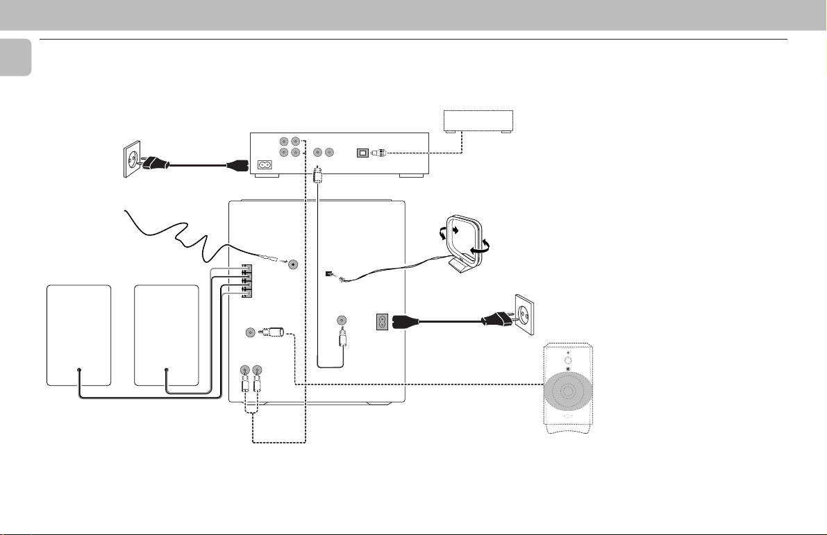
Rear Connections
LR
C
F
BB
B
FRONT
SUBWOOFER
OUT
AUX IN
Connections general
The connections you make will depend
upon the possibilities your audio equipment
offers. Please refer to the user manuals for
D
CD RECORDER
L
L
R
R
MAINS
IN
ANALOG
OUT
IN
DIGITAL
IN
OUT
OPTICAL
CD PLAYER
DIGITAL
OPTICAL
OUTPUT
A
FM AERIAL
75Ω
+
R
–
–
L
+
AM AERIAL
DIGITAL
OUT
AC
MAINS
~
F
STANDBY ON
E
V
L
E
R
L
E
F
C
O
O
N
O
T
W
R
B
U
S
MIN MAX
CUT OFF FREQUENCY
HIGH POWER SUBWOOFER
60Hz 150Hz
E
your other audio equipment first.
Digital recordings (optical or coaxial) give
the best performance in audio and
usability (e.g. auto-track). (The digital
optical connection is less sensitive to
external disturbances). If your equipment
does not offer digital connections, the high
quality Analog-Digital-Convertor of your CD
recorder will ensure very good audio
performance when recordings are made
from the analog input.
Playback via the digital coaxial output of
the CD recorder gives the best audio
performance. If your equipment does not
offer digital connections, the high quality
Digital-Analog-Convertor of the CD
recorder ensures a very good sound quality
O
L
via the analog output.
We advise you to always establish both
digital and analog connections. In this way
you can always make analog recordings
when digital recording is not possible.
6
PREPARATION
A AM Loop Antenna
Connection
Connect the supplied loop antenna to the
AM AERIAL terminal. Place the AM loop
antenna far away from the system and
adjust its position for the best reception.
B FM Wire Antenna
Connection
Connect the supplied FM wire antenna to
the FM 75 Ω terminal. Adjust the position
of the FM antenna for the best reception.
Outdoor Antenna
For better FM stereo reception connect an
outdoor FM antenna to the FM AERIAL 75
Ω terminal using a 75 Ω coaxial wire.
C Speaker Connections
• Connect the right speaker to Front
terminal R, with the colored wire to +
and the black wire to -.
• Connect the left speaker to Front
terminal L, with the colored wire to +
and the black wire to -.
• Clip the stripped portion of the speaker
wire as shown.
12 mm
unlock lock
D CD Recorder Connections
ANALOG CONNECTIONS
Connect the red plugs to the R sockets, and
the white plugs to the L sockets.
For recording
Connect cable between the ANALOG INsockets on the CD recorder CDR LINE- or
TAPE OUT-sockets of an amplifier.
Note:
– For recording directly from a CD player,
the analog input of the CD recorder
should be connected to the analog
output of the CD player.
For playback
Connect cable between the ANALOG OUTsockets on the CD recorder and the AUX IN
sockets on the mini system, or the input
sockets of an amplifier e.g. TAPE IN, CDR
or AUX.
Note:
– Never use the PHONO input.
DIGITAL COAXIAL CONNECTIONS
For recording
Connect the cable between the DIGITAL INsocket on the CD recorder and the DIGITAL
OUT-socket of the mini system or CD
player.
For playback
Connect the cable between the DIGITAL
OUT-socket on the CD recorder and the
digital coaxial input of an amplifer or
recording device.
Note:
– Digital coaxial connection is only
required in case you wish to record from
a CD player with digital coaxial output.
DIGITAL OPTICAL CONNECTIONS
For recording
Connect a fibre-optic cable
between the IN OPTICAL of the CD
recorder and the digital-optical output of a
CD player.
Notes:
– Digital optical connection is only
required in case you wish to record from
a CD player with digital optical output.
– For playback, the digital coaxial output
or analog output should be connected to
an amplifier.
– When connecting the Digital Optical
cable, make sure it is fully inserted until
there is a click.
(not supplied)
E Subwoofer Out Connection
Connect the optional active subwoofer to
the SUBWOOFER OUT terminal. The
subwoofer reproduces just the low bass
effect (e.g. explosions, the rumble of
spaceships, etc.). Be sure to follow the
instructions supplied with the subwoofer.
F AC Power Supply
After all other connections have been
made, connect the AC power cord to the
system and to the wall outlet.
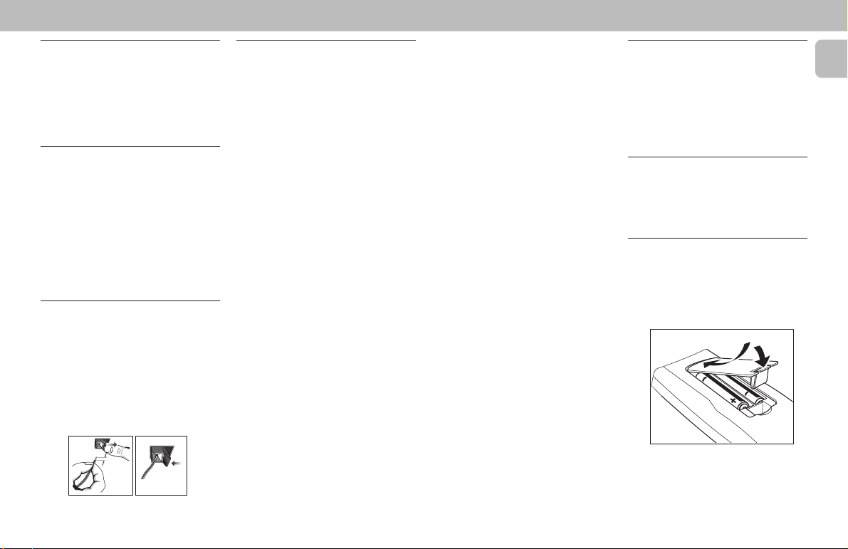
Inserting batteries into the
Remote Control
• Insert the batteries (Type R06 or AA)
into the remote control as shown in the
battery compartment.
• To avoid damage from possible battery
leakage, remove dead batteries or
batteries that will not be used for a long
time. For replacement, use type R06 or
AA batteries.
English
7
CONTROLS
English
@
!
0
9
8
7
8
2
1
6
5
4
3
∞
OPTIMAL
DSC DBB
TECHNO
DIGITAL SOUND CONTROL
STANDBY.ON
DUBBING
RECORD A. REPLAY
NORM•FAST
DISC
1
DISC
2
DISC
3
REC
STEREO
JAZZ
ROCK
REPEAT
PROGRAM
SHUFFLE
REPLAY
TIMER
DBB
NEWS
I S
HSD
MW
FM
AM
PMLW
FW 318C
CD TUNER TAPE AUX
CD
1
• 2 •
3
▲▲▲
TUNING
SEARCH
BAND
▲
DEMO
STOP•CLEAR
TAPE 1 • 2
PAUSE
PLAY
DISC CHANGE
MAX
VIDEO
▲
PRESET
PREV NEXT
OPEN • CLOSE
RDS NEWS!
CLOCK
TIMER
▲
PROGRAM
3
CHANGER
INCREDIBLE SURROUND
#
$
DC
%
^
2
&
*
•
(
(
)
)
3
n
¡
9
§
OPENOPEN
AUX
CD 1/2/3
1
4
7
í
à
DBB DSC
TAPE 1/2 TUNER
2
5
8
0
VOLUME
É
Ç
Å
SIDE
SHUFFLE
REPEAT
INTRO
TRACK
SCAN
INCREMENT
2
CDR
=
3
6
9
PROG.INC. SURR.
*
)
ë
á
7
≥
™
≤
£
TAPE 1 TAPE 2
8

CONTROLS
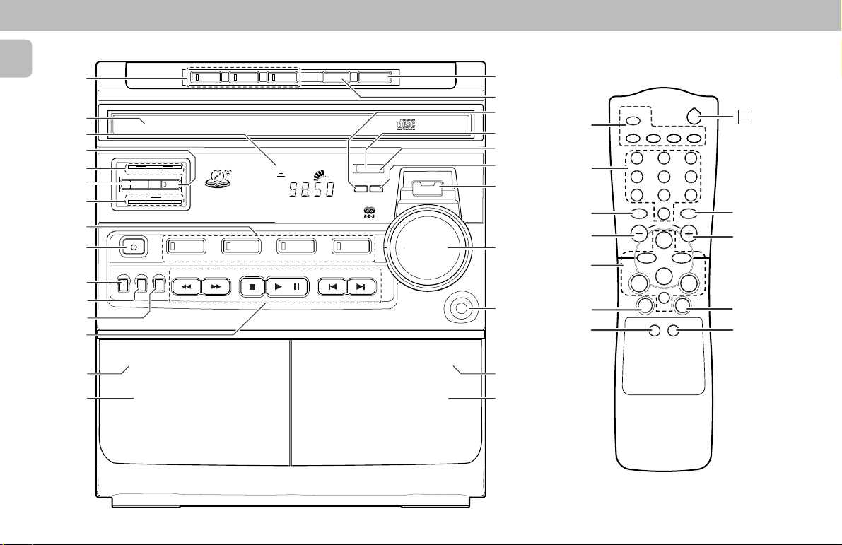
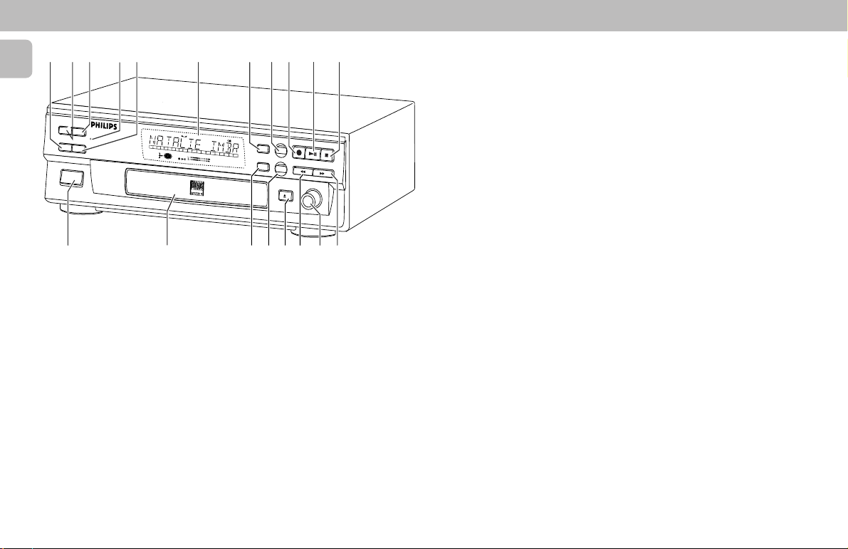
Controls on the system and
remote control
1 STANDBY-ON
– to switch the system on or to standby
mode.
– to store radio stations automatically
by pressing and holding for 5 seconds.
2 SOURCE : to select the following.
CD / (CD 1•2•3)
– to select CD mode. When CD in stop
mode; to select the disc tray 1, 2 or 3.
TUNER / (BAND)
– to select Tuner mode. When in tuner
mode; to select the waveband: FM,
MW or LW.
TAPE / (TAPE 1• 2)
– to select Tape mode. When tape in
stop mode; to select either tape deck
1 or 2.
AUX / (VIDEO)
– to select sound from an external
source (e.g. TV, Laser Disc, DVD,VCR
player or CD Recorder).
3 MODE SELECTION
SEARCH à á (TUNING à á)
for CD ............ to search backward/
forward.
for TUNER ..... to tune to a lower or
higher radio frequency.
for TAPE ........ to rewind or fast
forward on tape deck 2
only.
for CD Recorder…to search
backward/forward.
...................... cursor control in Menu/
Prog. review mode.
STOP•CLEAR Ç (DEMO)
for CD ............ to stop CD playback or
for TUNER ..... to stop programming.
clear a program.
(on the system only)
for TAPE ........ to stop playback or
DEMO ........... to start or stop
recording.
demonstration mode
(on the system only)
for CD Recorder…to stop or clear a
PLAY É / PAUSEÅ
for CD ............ to start or interrupt
for TAPE ........ to start playback.
for CD Recorder…to start playback/
PREV í / NEXT ë (PRESET 4 3)
for CD ............ to skip to the beginning
for TUNER ..... to select a preset
4 AUTO REPLAY
program.
playback.
interrupt playback or
recording.
of the current or
previous/next track.
station in memory.
(available in tape
deck 2 only)
– to select playback mode either in
continuous AUTO PLAY or ONCE only.
5 RECORD
– to start recording on tape deck 2 only.
for CD Recorder
– to start recording, finalizing and
erasing.
6 DUBBING
– to dub a tape in normal or fast speed.
7 DIGITAL SOUND CONTROL (DSC)
– to select the desired sound effect :
OPTIMAL, JAZZ, ROCK or TECHNO.
8 DIGITAL SOUND CONTROL
DISPLAY PANEL
– to view the selected DSC display.
9 DYNAMIC BASS BOOST (DBB)
– to switch on bass boost to enhance
bass response or to switch off bass
boost.
0 DISPLAY SCREEN
– to view the current setting of the
system.
! CD CAROUSEL TRAY
@ CD DIRECT PLAY (DISC 1 / DISC 2 /
DISC 3)
– to select a CD tray for playback.
# OPEN•CLOSE
– to open or close the CD carousel tray.
for CD Recorder
– to open or close the disc tray.
$ DISC CHANGE
– to change CD(s).
% CLOCK/TIMER
– to view clock, set clock or timer.
^ RDS
– to select RDS data.
& NEWS!
– to hear news at a preset time
automatically.
* PROGRAM
– to program CD tracks in CD mode or
preset radio stations in tuner mode.
( INCREDIBLE SURROUND
– to switch on or off the surround sound
effect.
) VOLUME
– to adjust the volume level.
¡ n
– to connect headphones.
™ OPEN
– to open tape deck 2.
£ TAPE DECK 2
≤ TAPE DECK 1
∞ OPEN
– to open tape deck 1.
§ REPEAT/INTRO SCAN
– to repeat a CD track.
– to play the first 10 seconds of each
track
(only for CD operation)
≥ SHUFFLE/TRACK INCREMENT
– to play all the available discs and their
tracks in random order.
– to increase track numbers during
recording
• Digit 0 - 9
– (numbers consisting of two figures
– to key in a CD track
(only for CD operation)
must be keyed in within 2 seconds).
CDR operation)
.
.
.
number (only for
English
9
CONTROLS
English
‚ · ° ‡ªfl fi0 335›
ERASE
SCROLL
FINALIZE
DISPLAY
CDR
ON/OFF
MINI AUDIO
CD RECORDER
REM
123456789
DIGITAL
I
OPTICAL
I
ANALOG
CD
TRACKREC TIME
REMTOTAL
TIME STEPTRACK
10
11
12
13
14
15
16
17
PROGRAM
RW
MANUAL
SHUFFLE
Recordable
º ⁄ ¤ # 3‹3
ª ON/OFF
– to turn the CD recorder ON or OFF.
º CD RECORDER DISC TRAY
⁄ CANCEL
– to delete tracks from a program.
– to delete text in Menu mode.
– to return to a higher level in the menu.
¤ MENU/STORE
– to select Menu mode.
– to store Menu settings.
‹ EASY JOG-rotate
– to skip to the previous/next track in
10
(on CD Recorder only)
(on CD Recorder only)
(on CD Recorder only)
(on CD Recorder
only)
Playback or Program mode.
REC TYPE
SOURCE
RECORD
PLAY/PAUSE
18
19
20 +
MENU/STORE
CANCEL
SYNC
SCAN
REPEAT
TRACK
ALL
OPEN/CLOSE
REWIND
STOP
FFWD
EASY JOG
ENTER
– to control recording level in Recording
mode.
– to select settings in Menu mode.
ENTER-push
– to play the selected tracks.
– to select settings in Menu mode.
– to program track numbers.
› REC TYPE
(on CD Recorder only)
– to select recording mode.
fi SOURCE
(on CD Recorder only)
– to select input source.
fl DISPLAY
(on CD Recorder only)
– to select display information/text.
‡ STANDBY INDICATOR
(on CD
Recorder only)
° FINALIZE
(on CD Recorder only)
– to select finalize mode.
· ERASE
(on CD Recorder only)
– to select erasing mode.
‚ SCROLL
(on CD Recorder only)
– to activate scrolling of text over the
display (once).
= B
– to switch the system to standby mode.
Notes for remote control:
– First select the source you wish to
control by pressing one of the
source select keys on the remote
control (e.g. CD 1/2/3, TAPE 1/2,
TUNER, or CDR).
– Then select the desired function
(
É, í, ë
, etc).
 Loading...