

Page 1

Disassembly and
This document has been printed from SPI². Not for Resale
Assembly
KENR6226-01
April 2008
402D-403
GG (Engine)
ngine)
GH
(E
(Engine)
GJ
(Engine)
GK
ngine)
GL (E
GM
(Engine)
(Engine)
GN
Engine)
(
GP
GQ
(Engine)
GS
(Engine)
D-404D Industrial Engine
SAFETY.CAT.COM
Page 2

Important Safety Information
This document has been printed from SPI². Not for Resale
Most accidents that involve product operation, maintenance and repair are caused by failure to
observe basic safety rules or precautions. An accident can often be avoided by recognizing potentially
hazardous situations before an accident occurs. A person must be alert to potential hazards. This
person should also have the necessary training, skills and tools to perform these functions properly.
Improper operation, lubrication, maintenance or repair of this product can be dangerous and
could result in injury or death.
Do not operate or perform any lubrication, maintenance or repair on this product, until you have
read and understood the operation, lubrication, maintenance and repair information.
Safety precautions and warnings are provided in this manual and on the product. If these hazard
warnings are not heeded, bodily injury or death could occur to you or to other persons.
The hazards are identified by the “Safety Alert Symbol” and followed by a “Signal Word” such as
“DANGER”, “WARNING” or “CAUTION”. The Safety Alert “WARNING” label is shown below.
The meaning of this safety alert symbol is as follows:
Attention! Become Alert! Your Safety is Involved.
The message that appears under the warning explains the hazard and can be either written or
pictorially presented.
Operations that may cause product damage are identified by “NOTICE” labels on the product and in
this publication.
Perkins cannot anticipate every possible circumstance that might involve a potential hazard. The
warnings in this publication and on the product are, therefore, not all inclusive. If a tool, procedure,
work method or operating technique that is not specifically recommended by Perkins is used,
you must satisfy yourself that it is safe for you and for others. You should also ensure that the
product will not be damaged or be made unsafe by the operation, lubrication, maintenance or
repair procedures that you choose.
The information, specifications, and illustrations in this publication are on the basis of information that
was available at the time that the publication was written. The specifications, torques, pressures,
measurements, adjustments, illustrations, and other items can change at any time. These changes can
affect the service that is given to the product. Obtain the complete and most current information before
you start any job. Perkins dealers or Perkins distributors have the most current information available.
When replacement parts are required for this
product Perkins recommends using Perkins
replacement parts.
Failure to heed this warning can lead to premature failures, product damage, personal injury or
death.
Page 3

KENR6226-01 3
This document has been printed from SPI². Not for Resale
Table of Contents
Table of Contents
Disassembly and Assembly Section
Fuel Filter Base - Remove and Install (403D-11,
403D-15, 403D-15T, 403D-17, 404D-15, 404D-22,
404D-22T and 404D-22TA Engines) ..................... 4
Fuel Filter Base - Remove and Install (402D-05 and
403D-07 Engines) ................................................. 5
Fuel Transfer Pump - Remove and Install (Mechanical
Fuel Transfer Pump) ............................................. 7
Fuel Transfer Pump - Remove and Install (Electrical
Fuel Transfer Pump) ............................................. 8
Fuel Injection Lines - Remove and Install .............. 9
Fuel Shutoff Solenoid - Remove and Install ........ 12
Fuel Injection Pump - Remove and Install ........... 13
Fuel Injector - Remove and Install ....................... 15
Turbocharger - Remove and Install ..................... 16
Exhaust Manifold - Remove and Install ............... 18
Inlet and Exhaust Valve Springs - Remove and
Install ........................................... ........................ 19
Inlet and Exhaust Valves - Remove and Install .... 22
Engine Oil Line - Remove and Install ................... 24
Engine Oil Cooler - Remove and Install ............... 26
Engine Oil Relief Valve - Remove and Install ....... 27
Engine Oil Pump - Remove .................................. 28
Engine Oil Pump - Install ...................................... 30
Water Pump - Remove and Install (403D-11,
403D-15, 403D-15T, 403D-17, 404D-15, 404D-22,
404D-22T and 404D-22TA Engines) ................... 32
Water Pump - Remove and Install (402D-05 and
403D-07 Engines) ............................................... 33
Water Temperature Regulator Housing - Remove and
Install .................................................................. 35
Water Temperature Regulator - Remove and Install
(402D-05 and 404D-07 Engines) ........................ 36
Water Temperature Regulator - Remove and Install
(403D-11, 403D-15, 403D-15T, 403D-17, 404D-15,
404D-22, 404D-22T and 404D-22TA Engines) ... 38
Flywheel - Remove ............................................... 39
Flywheel - Install ................................................... 40
Crankshaft Rear Seal - Remove and Install ......... 41
Crankshaft Wear Sleeve (Rear) - Remove and
Install ........................................... ........................ 43
Flywheel Housing - Remove and Install .............. 44
Flywheel Housing - Remove and Install (Engines with
Flywheel Housing and Back Plate) ..................... 45
Crankshaft Pulley - Remove and Install ............... 47
Crankshaft Front Seal - Remove and Install ......... 48
Housing (Front) - Remove .................................... 49
Housing (Front) - Disassemble ............................. 50
Housing (Front) - Assemble .................................. 52
Housing (Front) - Install ........................................ 55
Crankcase Breather - Remove and Install
(Turbocharged Engines) ..................................... 56
Crankcase Breather - Remove and Install (Naturally
Aspirated Engines) .............................................. 58
Valve Mechanism Cover - Remove and Install ..... 60
Rocker Shaft and Pushrod - Remove ................... 62
Rocker Shaft - Disassemble (403D-15, 403D-15T,
403D-17, 404D-
Engines) .............................................................. 62
Rocker Shaft - Disassemble (402D-05, 403D-07,
403D-11 and 40
Rocker Shaft - Assemble (403D-15,
403D-15T,403D-17, 404D-22, 404D-22T and
404D-22TA Eng
Rocker Shaft - Assemble (402D-05, 403D-07,
403D-11 and 404D-15 Engines) ......................... 65
Rocker Shaft a
Cylinder Head - Remove ...................................... 67
Cylinder Head - Install .......................................... 69
Lifter Group - R
Camshaft - Remove .............................................. 72
Camshaft - Disassemble ....................................... 73
Camshaft - Asse
Camshaft - Install .................................................. 74
Engine Oil Pan - Remove and Install ................... 76
Pistons and Conn
Pistons and Connecting Rods - Disassemble ....... 78
Pistons and Connecting Rods - Assemble ........... 80
Pistons and Conn
Connecting Rod Bearings - Remove (Connecting
rods in position) ................................................... 83
Connecting Rod B
in position) ........................................................... 83
Connecting Rod Bearings - Install ........................ 84
Crankshaft Main
Crankshaft Main Bearings - Install ........................ 86
Crankshaft - Remove ............................................ 88
Crankshaft - Inst
Bearing Clearance - Check ................................... 90
Coolant Temperature Switch - Remove and Install
(403D-11, 403D-1
404D-22, 404D-22T and 404D-22TA Engines) ... 91
Coolant Temperature Switch - Remove and Install
(402D-05 and 403
Engine Oil Pressure Switch - Remove and Install
............................................................................. 93
Glow Plugs - Remov
V-Belts - Remove and Install ................................ 96
Fan - Remove and Install ..................................... 96
Alternator-Remo
Alternators) ......................................................... 97
Alternator - Remove and Install (55 Amp
Alternator) ........................................................... 99
Alternator - Remove and Install (40 Amp
Alternator) ........................................................... 99
Alternator-Remo
Alternators) ....................................................... 101
Electric Starting Motor - Remove and Install ..... 102
22, 404D-22T and 404D-22TA
4D-15 Engines) ......................... 63
ines) ........................................... 64
nd Pushrod - Install ....................... 66
emove and Install ......................... 71
mble ........................................... 74
ecting Rods - Remove .............. 77
ecting Rods - Install .................. 81
earings - Install (Connecting rods
Bearings - Remove .................... 85
all ................................................ 89
5, 403D-15T, 403D-17, 404D-15,
D-07 Engines) ........................ 92
e and Install ......................... 95
veandInstall(65Ampand85Amp
veandInstall(14Ampand15Amp
Index Section
Index ............................... .................................... 103
Page 4
4 KENR6226-01
This document has been printed from SPI². Not for Resale
Disassembly and Assembly Section
Disassembly an
d Assembly
Section
i02959949
Fuel Filter Base - Remove and
Install
(403D-11, 40
403D-17, 404D-15, 404D-22,
404D-22T and 404D-22TA
Engines)
Removal Procedure
Do not allow dirt to enter the fuel system. Thoroughly
clean the are
will be disconnected. Fit a suitable cover over disconnected fuel system component.
Care must be taken to ensure that fluids are contained
during performance of inspection, maintenance, testing, adjusting and repair of the product. Be prepared to
collect the fluid with suitable containers before opening any compartment or disassembling any component containing fluids.
Dispose of all fluids according to local regulations and
mandates.
a around a fuel system component that
3D-15, 403D-15T,
NOTICE
NOTICE
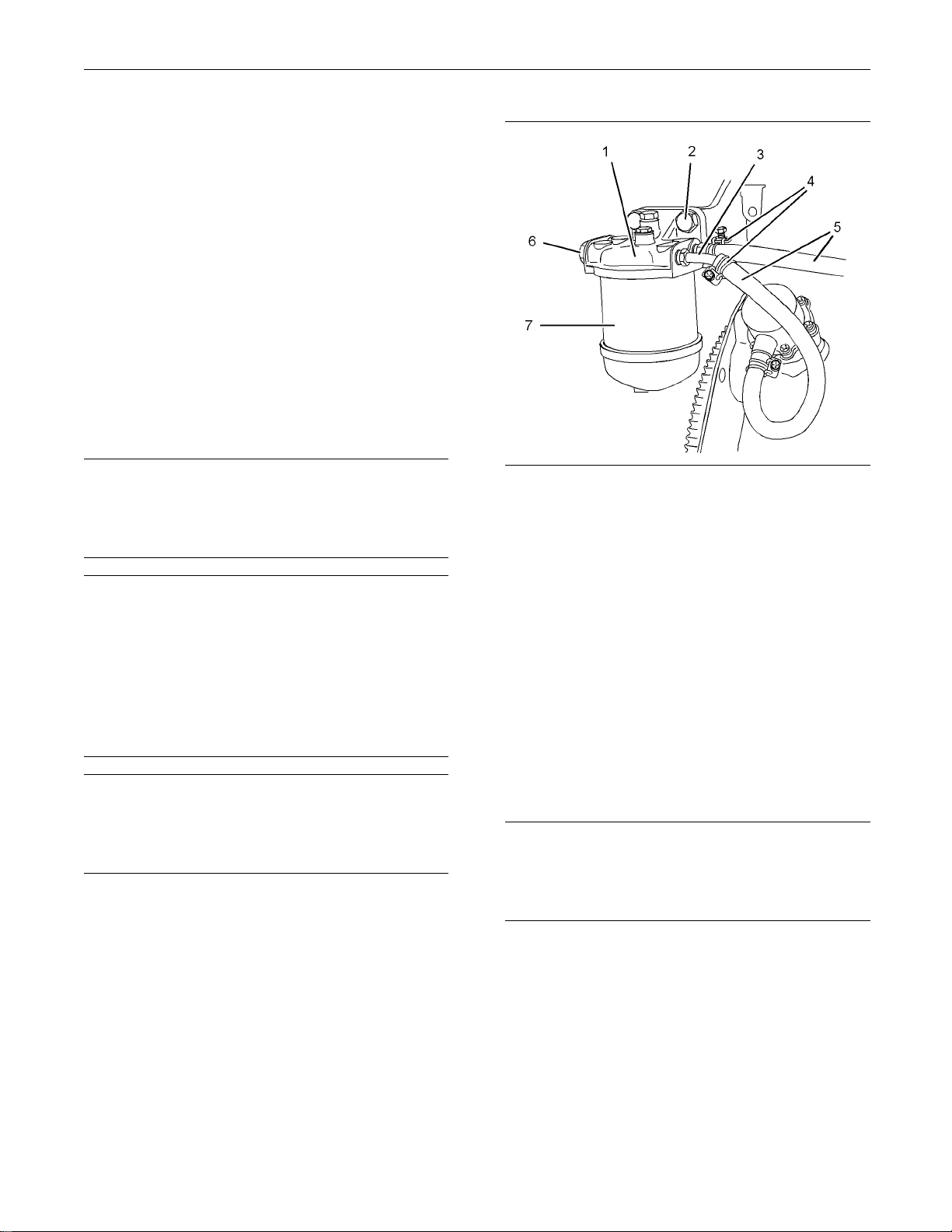
Illustration 1
Typical example
2. Loosen hose clamps (4) and disconnect hoses (5).
3. If necessary, remove fuel filter element (7)
from fuel filter base (1). Refer to Operation
and Maintenance Manual, “Fuel System Filter Replace”.
4. Remove fasteners (2) and remove fuel filter base
(1) from the mounting bracket.
5. If necessary, remove plugs (6) and washers (not
shown) from fuel filter base (1). Remove tube
assemblies (3) and rubber olives (not shown) from
fuel filter base (1).
g01302737
NOTICE
Keep all parts clean from contaminants.
Contaminan
component life.
Note: Place identification marks on all hoses for
installation purposes. Plug all hoses and all the ports
in the fuel filter base. This helps prevent fluid loss,
and this helps to keep contaminants from entering
the system.
1. Turn the fuel supply to the OFF position.
ts may cause rapid wear and shortened
Installation Procedure
NOTICE
Keep all parts clean from contaminants.
Contaminants may cause rapid wear and shortened
component life.
Note: If the engine is equipped with a hand priming
pump, the hand priming pump is mounted on the fuel
filter base. The assembly of the fuel filter base and
the hand priming pump is not serviceable.
1. Ensure that the fuel filter base is clean and free
from damage. If necessary, replace the fuel filter
base.
Page 5
KENR6226-01 5
This document has been printed from SPI². Not for Resale
Disassembly and Assembly Section
i02645711
Fuel Filter B ase - Remove and
Install
3D-07 Engines)
NOTICE
NOTICE
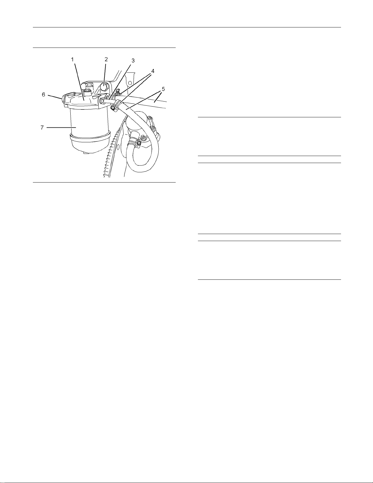
Illustration 2
Typical example
2. If necessary, install new rubber olives (not shown)
onto tube assemblies (3). Install tube assemblies
(3) to fuel filter base (1). Ensure the correct
orientation of the tube assemblies. Tighten the
nuts to a torque of 9 N·m (80 lb in).
g01302737
(402D-05 and 4 0
Removal Procedure
Do not allow dirt to enter the fuel system. Thoroughly
clean the area a
will be disconnected. Fit a suitable cover over disconnected fuel system component.
Care must be taken to ensure that fluids are contained
during performance of inspection, maintenance, testing, adjusting and repair of the product. Be prepared to
collect the fluid with suitable containers before opening any compartment or disassembling any component containing fluids.
Dispose of all fluids according to local regulations and
mandates.
round a fuel system component that
3. Install washers (not shown) onto plugs (6). Install
plugs (6) to fuel filter base (1). Tighten the plugs
to a torque of 23 N·m (17 lb ft).
4. Align fuel filter base (1) with the mounting bracket.
Install fasteners (2). Tighten the fasteners to a
torque of 50 N·m (37 lb ft).
5. If necessary, install a new fuel filter element
(7) to fuel filter base (1). Refer to Operation
and Maintenance Manual, “Fuel System Filter Replace”.
6. Connect hoses (5) and tighten hose clamps (4).
Note: Ensure that the hoses do not contact any other
engine components.
7. Turn the fuel supply to the ON position.
8. Remove the air from the fuel system. Refer to
Operation and Maintenance Manual, “Fuel System
- Prime”.
NOTICE
Keep all parts clean from contaminants.
Contaminants
component life.
Note: Place identification marks on all hoses for
installation purposes. Plug all hoses and all the ports
in the fuel filter base. This helps prevent fluid loss,
and this helps to keep contaminants from entering
the system.
1. Turn the fuel supply to the OFF position.
may cause rapid wear and shortened
Page 6
6 KENR6226-01
This document has been printed from SPI². Not for Resale
Disassembly and Assembly Section
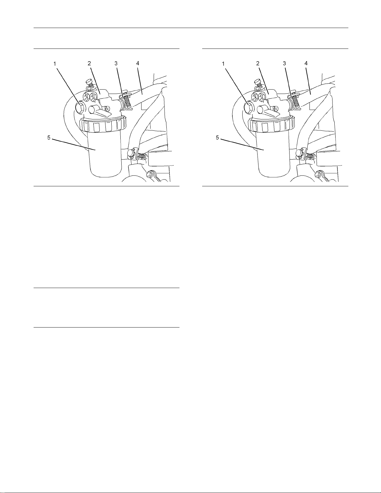
Illustration 3
Typical example
g01303701
2. Loosen hose clamps (3) and disconnect hoses (4).
3. If necessary, remove fuel filter element (5). Refer
to Operations and Maintenance Manual, “Fuel
System Filter - Replace”.
4. Remove bolt (1) and remove fuel filter base (2)
from the mounting bracket.
Installation Procedure
NOTICE
Keep all parts clean from contaminants.
Contaminants may cause rapid wear and shortened
component life.
1. Ensure that the fuel filter base is clean and free
from damage. If necessary, replace the fuel filter
base.
Illustration 4
Typical example
g01303701
2. Align fuel filter base (2) with the mounting bracket.
Install bolt (1). Tighten the bolt to a torque of
25 N·m (18 lb ft).
3. If necessary, install a new fuel filter element
(6) to fuel filter base (2). Refer to Operation
and Maintenance Manual, “Fuel System Filter Replace”.
4. Connect hoses (4) and tighten hose clamps (3).
Note: Ensure that the hoses do not contact any other
engine components.
5. Turn the fuel supply to the ON position.
6. Remove the air from the fuel system. Refer to
Operation and Maintenance Manual, “Fuel System
- Prime”.
Page 7
KENR6226-01 7
This document has been printed from SPI². Not for Resale
Disassembly and Assembly Section
i02645722
Fuel Transfer Pump - Remove
and Install
(Mechanical Fu
el Transfer
Pump)
Removal Proce
Do not allow di
clean the area around a fuel system component that
will be disconnected. Fit a suitable cover over disconnected fuel sy
Care must be taken to ensure that fluids are contained
during performance of inspection, maintenance, testing, adjusting and repair of the product. Be prepared to
collect the fluid with suitable containers before opening any compartment or disassembling any component containing fluids.
Dispose of all fluids according to local regulations and
mandates.
Keep all parts clean from contaminants.
Contaminants may cause rapid wear and shortened
component life.
Note: Place identification marks on all hoses for
installation purposes. Plug all hoses and all the
ports in the fuel transfer pump. This helps prevent
fluid loss, and this helps to keep contaminants from
entering the system.
rt to enter the fuel system. Thoroughly
stem component.
dure
NOTICE
NOTICE
NOTICE
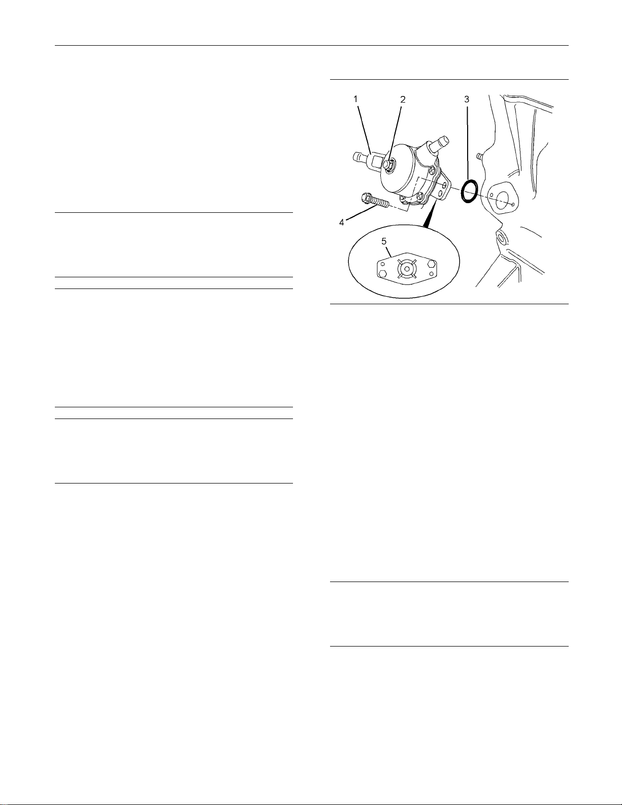
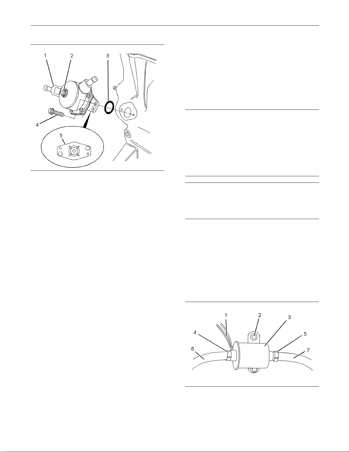
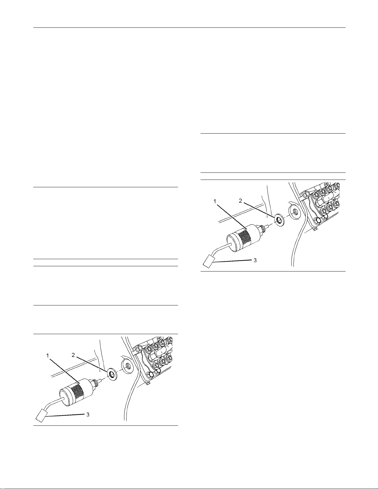
Illustration 5
Typical example
Note: The fuel transfer pump can be oriented in two
positions. Before removing the fuel transfer pump
from the cylinder block, note the orientation of flange
(5) on fuel transfer pump (1) for assembly.
2. Loosen the hose clamps and disconnect the
hoses (not shown) from fuel transfer pump (1).
3. Evenly loosen bolts (4) and remove fuel transfer
pump (1) from the cylinder block.
Note: In order to remove the fuel transfer pump, it
may be necessary to rotate the crankshaft until the
operating plunger of the fuel transfer pump is not
under pressure.
4. Remove O-ring seal (3) from fuel transfer pump
(1).
g01326306
1. Turn the fuel supply to the OFF position.
Installation Procedure
NOTICE
Keep all parts clean from contaminants.
Contaminants may cause rapid wear and shortened
component life.
Page 8
8 KENR6226-01
This document has been printed from SPI². Not for Resale
Disassembly and Assembly Section
i02645719
Fuel Transfer Pump - Remove
and Install
(Electrical Fu
Removal Procedure
Care must be taken to ensure that fluids are contained
during perform
ing, adjusting and repair of the product. Be prepared to
collect the fluid with suitable containers before opening any compar
nent containing fluids.
ance of inspection, maintenance, test-
el Transfer Pump)
NOTICE
tment or disassembling any compo-
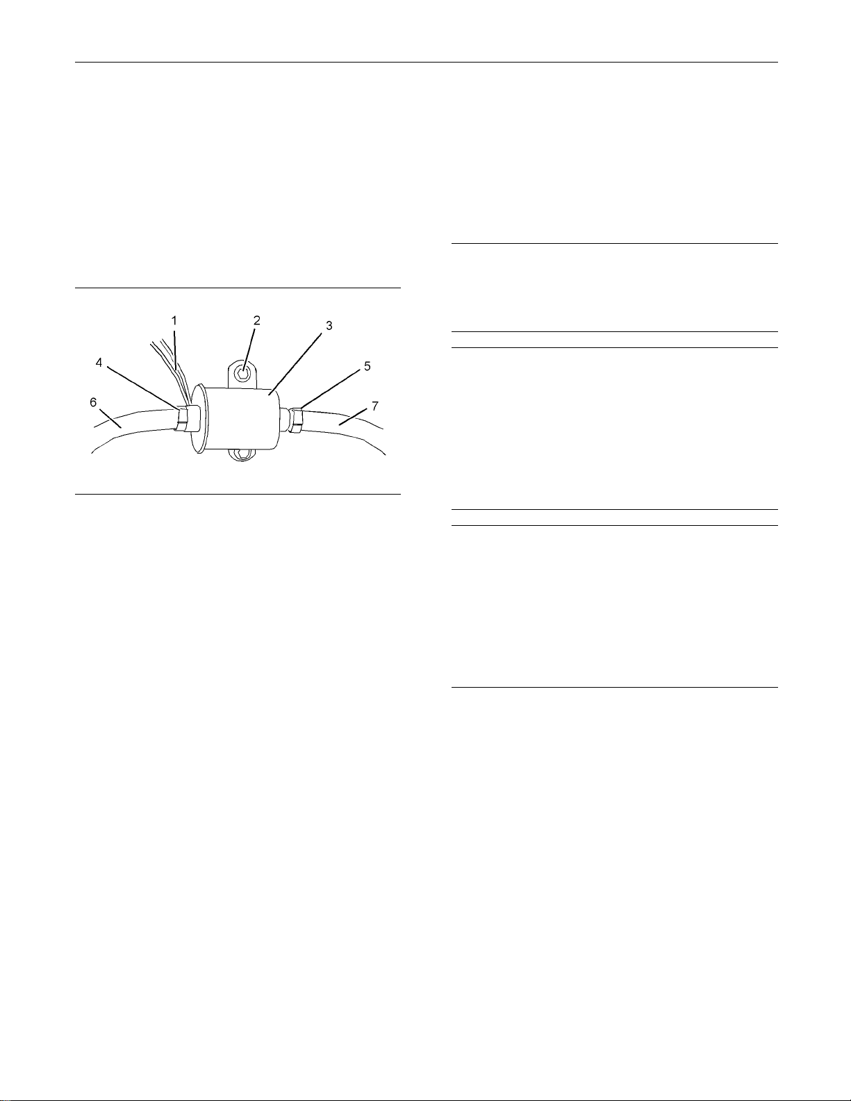
Illustration 6
Typical example
1. Clean the mating surfaces of the cylinder block
and flange (5) on the fuel transfer pump.
Note: Ensure that the camshaft lobe for the fuel
transfer pump is at minimum lift before the fuel
transfer pump is installed. The fuel transfer pump
canbeorientedintwopositions.Ensurethatthefuel
transfer pump is oriented in the correct position.
2. Install a new O-ring seal (3) to fuel transfer pump
(1).
3. Lubricate the operating plunger of fuel transfer
pump (1) with clean engine oil.
4. Position fuel transfer pump (1) on the cylinder
block. Ensure that the operating plunger is
positioned correctly on the camshaft lobe. Install
bolts (4). Tighten the bolts to a torque of 6 N·m
(53lbin).
5. Connect the hoses (not shown) to fuel transfer
pump (1). Tighten the hose clamps.
g01326306
Dispose of all
mandates.
Keep all parts clean from contaminants.
Contaminants may cause rapid wear and shortened
component life.
Note: Put identification marks on all hoses, on all
hose assembl
for installation purposes. Plug all hose assemblies
and tube assemblies. This helps to prevent fluid loss
and this help
the system.
1. Turn the fue
2. Turn the battery disconnect switch to the OFF
position.
fluids according to local regulations and
NOTICE
ies, on wires and on all tube assemblies
s to keep contaminants from entering
l supply to the OFF position.
Note: The inlet for the fuel transfer pump can be
rotated 360 degrees by loosening bolt (2). The
fuel inlet is adjustable in 15 degree increments. If
adjustment is made to the position of the fuel inlet,
tighten bolt (2) to a torque of 2.5 N·m (22 lb in).
6. Turn the fuel supply to the ON position.
7. Prime the fuel system. Refer to Systems
Operation, Testing and Adjusting, “Fuel System Prime” for additional information.
Illustration 7
Typical ex
3. Disconnect harness assembly (1).
ample
g01304057
Page 9
KENR6226-01 9
This document has been printed from SPI². Not for Resale
Disassembly and Assembly Section
4. Loosen hose clamps (4) and (5). Disconnect
hoses (6) and (7
5. Remove bolts (2) and remove electric transfer
pump (3).
Installation
1. Ensure that the electric transfer pump is clean
and free from d
electric transfer pump.
Illustration 8
Typical example
2. Position el
and install bolts (2).
).
Procedure
amage. If necessary, replace the
g01304057
ectric transfer pump (3) on the mounting
i02959953
Fuel Injection Lines - Remove
and Install
Removal Procedure
NOTICE
Keep all parts clean from contaminants.
Contaminants m
component life.
Care must be taken to ensure that fluids are contained
during performance of inspection, maintenance, testing, adjusting
collect the fluid with suitable containers before opening any compartment or disassembling any component contain
Dispose of all fluids according to local regulations and
mandates.
Do not let the tops of fuel injectors turn when the fuel
line nuts are loosened or tightened.
ay cause rapid wear and shortened
NOTICE
and repair of the product. Be prepared to
ing fluids.
NOTICE
3. Tighten bol
4. Connect hoses (6) and (7). Tighten hose clamps
(4) and (5)
5. Connect harness assembly (1).
6. Turn the fuel supply to the ON position.
7. Turn the ba
position.
8. Remove the
Operation and Maintenance Manual, “Fuel System
- Prime”.
ts (2) to a torque of 9 N·m (79 lb in).
.
ttery disconnect switch to the ON
air from the fuel system. Refer to
The fuel injectors will be damaged if the top of the
injector turns in the body.
The engine will be damaged if a defective fuel injector
is used because the shape of fuel (spray pattern) that
comes out of the nozzle will not be correct.
Note: Place identification marks on all tube
assemblies for installation. Plug all lines and tube
assemblies in order to prevent contamination.
1. Turn the fuel supply to the OFF position.
Page 10
10 KENR6226-01
This document has been printed from SPI². Not for Resale
Disassembly and Assembly Section
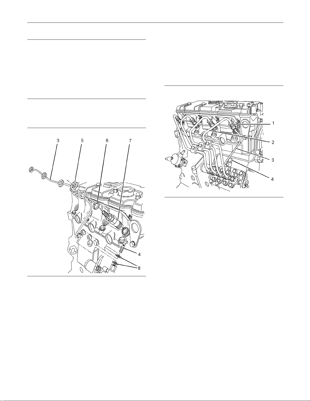
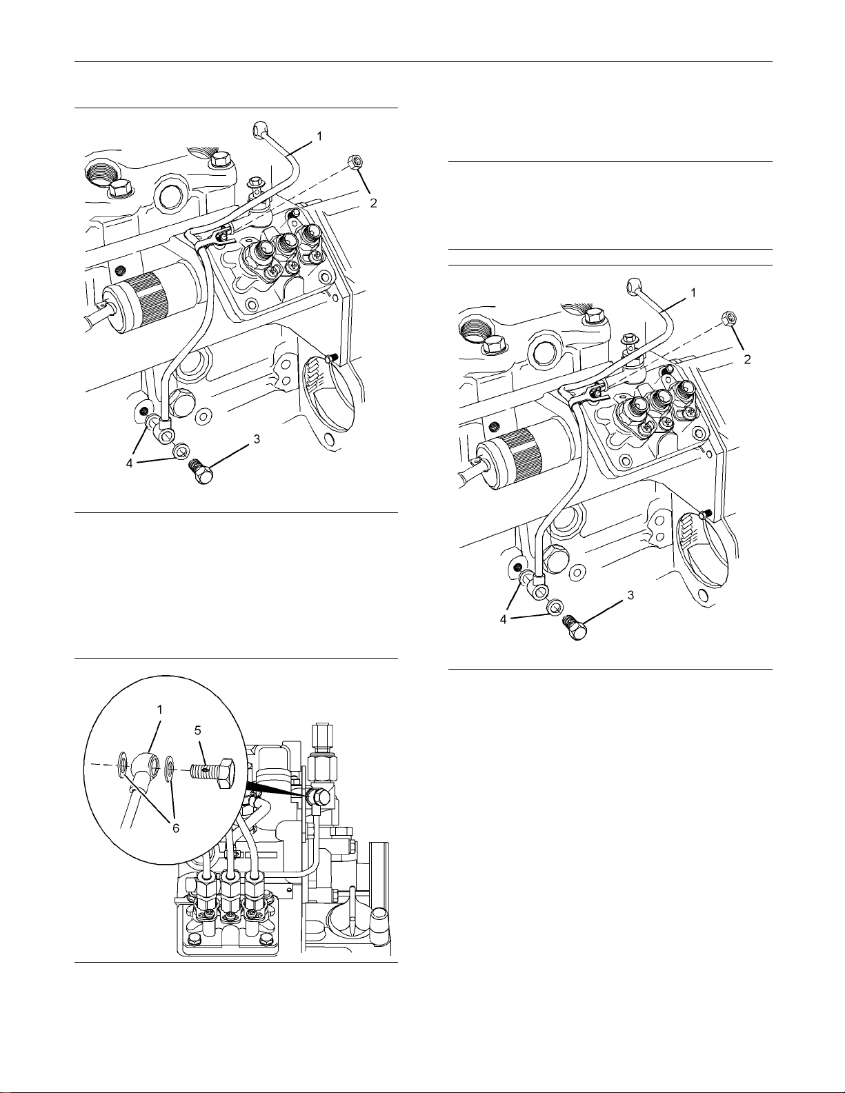
Illustration 9
Typical example
g01326550
2. Disconnect nuts (1) for fuel injection lines (2) from
the fuel injectors.
3. Disconnect nuts (1) for fuel injection lines (2) from
the fuel injection pump.
4. Remove fuel injection lines (2) from the engine
as a unit.
5. Use suitable caps in order to plug the open ports
of the fuel injection pump immediately.
6. The 403D-15, 403D-15T, 403D-17, 404D-22,
404D-22T and 404D-22TA engines have a rigid
fuel return line.
For engines with a rigid fuel return line, remove
banjo bolt (4) from fuel return line (3). Rem ove
washers (8).
The 402D-05, 403D-07, 403D-11 and 404D-15
engines have a flexible fuel return hose.
For engines with a flexible fuel return hose,
disconnect the hose from the fuel injection pump.
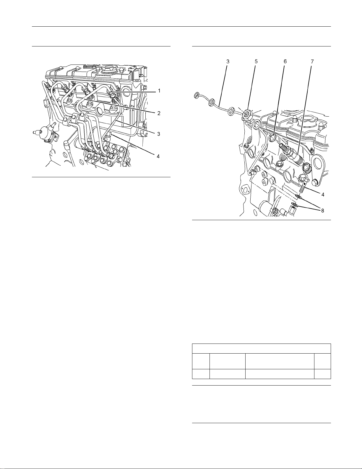
ion 10
Illustrat
Typical example
g01326555
7. Remove nuts (5) from fuel injectors (7).
Note: For e
ngines with a rigid fuel return line, ensure
that the fuel return line is not distorted when the nuts
are loosened.
8. Remove fuel return line (3) and washers (6) from
fuel injectors (7).
9. Use suitable caps in order to plug the fuel injectors
immediately.
Installation Procedure
Table 1
Tools
Part Name Qty
Pipe Nut Tool
1
Tool
A
Part
Number
27610294
Required
Injector
NOTICE
Keep all parts clean from contaminants.
Contaminants may cause rapid wear and shortened
component life.
Page 11
KENR6226-01 11
This document has been printed from SPI². Not for Resale
Disassembly and Assembly Section
The 402D-05, 403D-07, 403D-11 and 404D-15
NOTICE
engines have a fl
exible fuel return hose.
Do not let the tops of fuel injectors turn when the fuel
line nuts are lo
osened or tightened.
The fuel injectors will be damaged if the top of the
injector turns
in the body.
For engines with a flexible fuel return hose,
connect the fu
el return hose to the fuel injection
pump.
4. Tighten nuts (
5)toatorqueof27N·m(20lbft).
The engine will be damaged if a defective fuel injector
is used becaus
e the shape of fuel (spray pattern) that
comes out of the nozzle will not be correct.
Note: The installation procedure is similar for the
two cylinder,
the three cylinder and the four cylinder
engines.
Illustration 11
Typical e
xample
g01326555
1. Remove the caps from fuel injectors (7). Install
new washe
rs (6) and fuel return line (3) to fuel
injectors (7).
Note: Th
e washers (6) have two small holes.
2. Install nuts (5) to fuel injectors (7).
3. The 403D-15, 403D-15T, 403D-17, 404D-22,
404D-22TA and 404D-22TA engines have a rigid
fuel ret
urn line.
For engines with a rigid fuel return line, install new
washers
(8) to fuel return line (3) and install banjo
bolt (4) to the fuel injection pump. Tighten banjo
bolt (4) to a torque of 7 N·m (62 lb in).
Illustration 12
Typical example
g01326550
5. Remove the caps from the outlet connections of
the fuel injection pump. Install the fuel injection
lines to the engine as a unit.
6. Connect fuel injection lines (2) to fuel injectors (7).
Tighten the union nuts (1) finger tight.
7. Use Tooling (A) to tighten union nuts (1) at the fuel
injection pump.
For 402D-05 and 403D-07 engines, tighten union
nuts (1) to a torque of 20 N·m (15 lb ft).
For 403D-11, 403D-15, 403D-15T, 403D-17,
404D-15, 404D-22, 404D-22T and 404D-22TA
engines, tighten the union nuts (1) to a torque of
23 N·m (17 lb ft).
Note: For the three cylinder and the four cylinder
engines, tighten the center union nuts first.
8. Use Tooling (A) to tighten union nuts (1) at the fuel
injections.
For 402D-05 and 403D-07 engines, tighten union
nuts (1) to a torque of 20 N·m (15 lb ft).
Page 12
12 KENR6226-01
This document has been printed from SPI². Not for Resale
Disassembly and Assembly Section
For 403D-11, 403D-15, 403D-15T, 403D-17,
404D-15, 404Dengines, tighten the union nuts (1) to a torque of
23 N·m (17 lb ft).
9. Turn the fuel supply to the ON position.
10. Prime the fuel
Maintenance Manual, “Fuel System - Prime” for
more information.
22, 404D-22T and 404D-22TA
system. Refer to Operation and
i02645718
Fuel Shutof f Solenoid Remove an d In
Removal Procedure
Care must be taken to ensure that fluids are contained
during perfo
ing, adjusting and repair of the product. Be prepared to
collect the fluid with suitable containers before opening any compa
nent containing fluids.
rmance of inspection, maintenance, test-
rtment or disassembling any compo-
stall
NOTICE
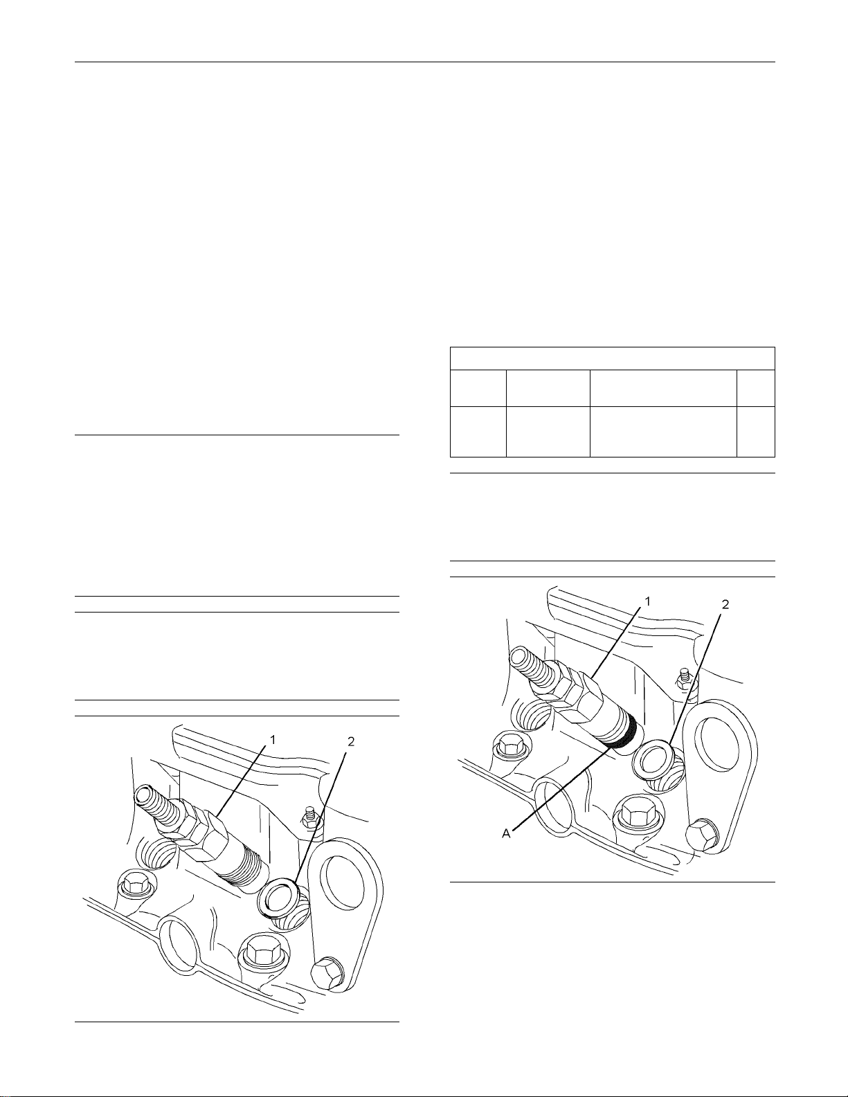
2. Disconnect electrical connection (3) from
the harness ass
connections for installation.
3. Remove fuel sh
injection pump housing by rotating the fuel shutoff
solenoid in a counterclockwise direction.
4. Remove sealing washer (2) from fuel shutoff
solenoid (1).
embly (not shown). Mark all
utoff solenoid (1) from the fuel
Installation Procedure
NOTICE
Keep all parts clean from contaminants.
Contaminants may cause rapid wear and shortened
component life.
Dispose of a
mandates.
Keep all parts clean from contaminants.
Contaminants may cause rapid wear and shortened
component life.
1. Turn the battery disconnect switch to the OFF
position.
ll fluids according to local regulations and
NOTICE
Illustration 14
Typical example
1. Install sealing washer (2) to fuel shutoff solenoid
(1).
2. Install fuel shutoff solenoid (1) into the fuel
injection pump housing by rotating the fuel shutoff
solenoid in a clockwise direction. Tighten the fuel
shutoff solenoid to a torque of 17 N·m (12 lb ft).
3. Connect electrical connection (3) to the harness
assembly (not shown).
4. Turn the battery disconnect switch to the ON
position.
g01326564
Illustration 13
Typical e
xample
g01326564
Page 13
KENR6226-01 13
This document has been printed from SPI². Not for Resale
Disassembly and Assembly Section
i02959957
Fuel Injection Pump - Remove
and Install
Removal Procedure
Start By:
a. Remove the fuel shutoff solenoid. Refer to
Disassembly a
Solenoid - Remove and Install”.
Care must be taken to ensure that fluids are contained
during perfor
ing, adjusting and repair of the product. Be prepared to
collect the fluid with suitable containers before opening any compa
nent containing fluids.
Dispose of al
mandates.
nd Assembly, “Fuel Shutoff
NOTICE
mance of inspection, maintenance, test-
rtment or disassembling any compo-
l fluids according to local regulations and
Illustration 15
Typical example
g01327005
NOTICE
Keep all parts clean from contaminants.
Contaminants may cause rapid wear and shortened
component life.
Note: The removal procedure is similar for the two
cylinder, t
engines. The Illustrations show a four cylinder engine.
1. Remove the f
he three cylinder and the four cylinder
uel injection lines. Refer to
Disassembly and Assembly, “Fuel Injection Lines
- Remove and Install” for more information.
The 402D-05, 403D-07, 403D-11 and 404D-15
engines have a flexible fuel return hose.
For engines with a flexible fuel return hose,
disconnect the fuel hose from the inlet connection
of the fuel
injection pump.
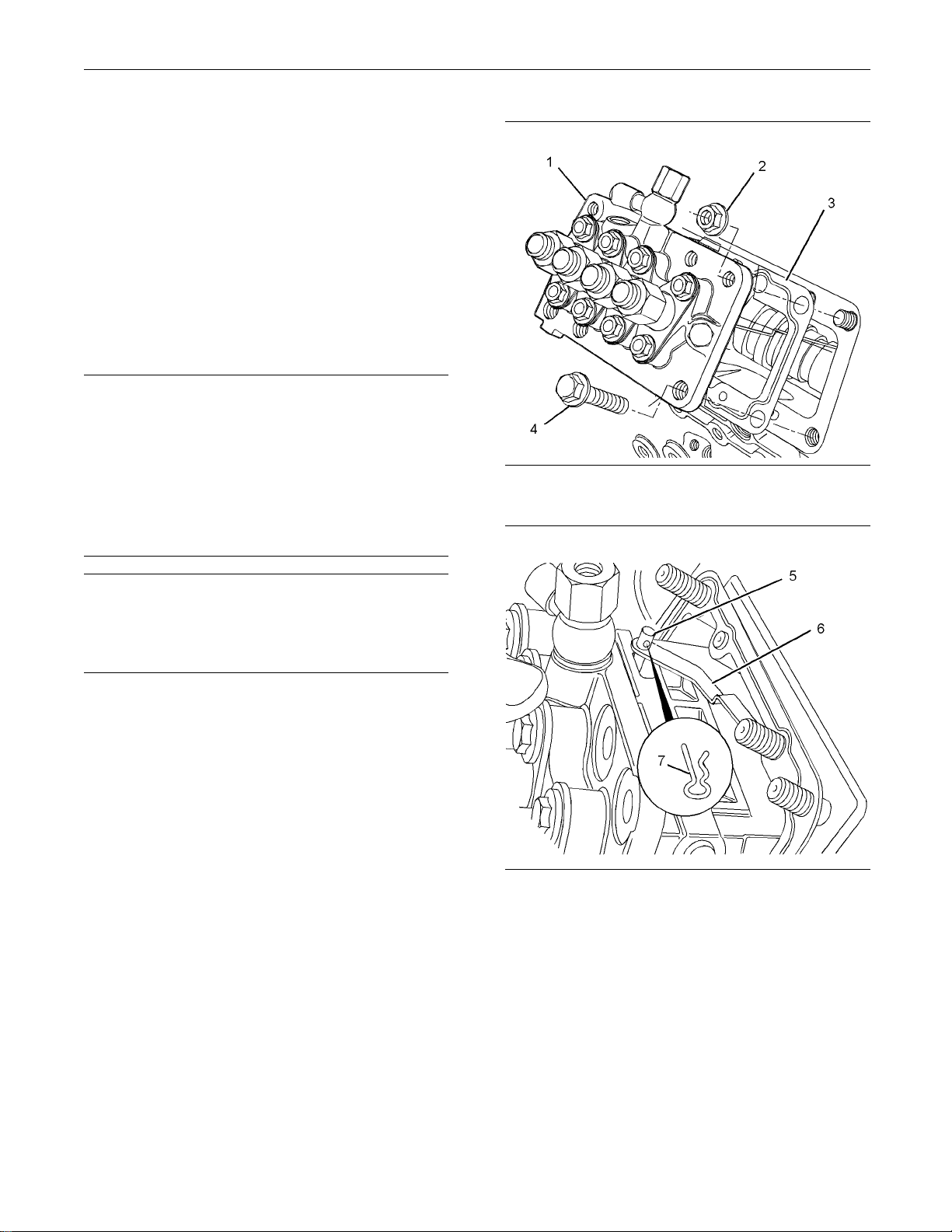
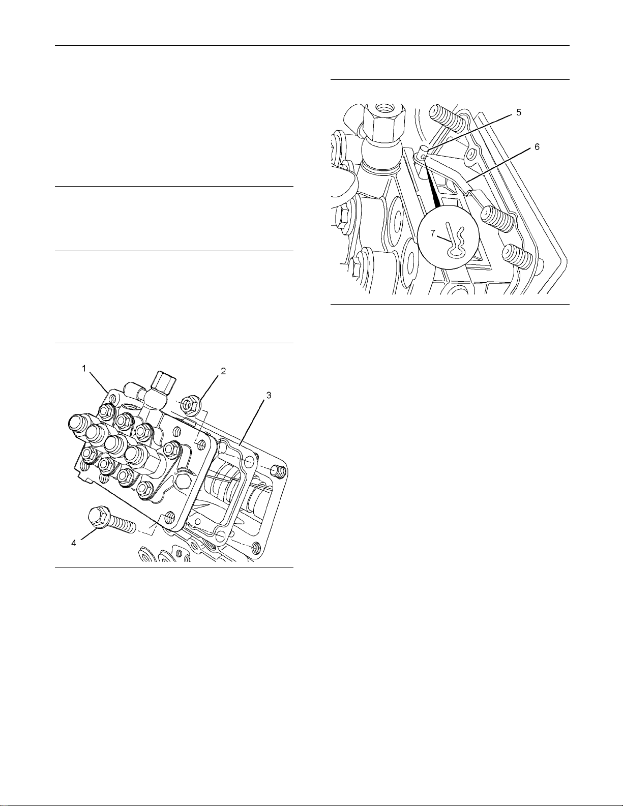
Illustration 16
Typical example
2. Gradual
the fuel injection pump to the cylinder block.
3. Careful
cylinder block and remove clip (7) that connects
link (6) to fuel rack control (5).
ly loosen bolts (4) and nuts (2) that fasten
ly raise fuel injection pump (1) from the
g013270
06
4. Remove fuel injection pump (1) from the cylinder
block.
5. Remove shims (3) from the mounting face of the
cylinder block.
Page 14
14 KENR6226-01
This document has been printed from SPI². Not for Resale
Disassembly and Assembly Section
Note: Record the thickness of each shim and the
number of shims
for reassembly. The fuel injection
timing is determined by the thickness of the shim
pack that is between the fuel injection pump and
the mounting f
ace on the cylinder block. Refer
to Specifications, “Fuel Injection Pump” for more
information.
Installation Procedure
NOTICE
Keep all parts clean from contaminants.
Contaminants may cause rapid wear and shortened
component life.
Note: The installation procedure is similar for the
two cylinder, the three cylinder and the four cylinder
engines. The Illustrations show a four cylinder engine.
1. Clean the mating surfaces of the cylinder block
and the fuel injection pump.
Illustration 17
Typical example
g01327005
2. New shims (3) must be used during assembly.
Install the correct thickness and the correct
number of shims on the mounting face of the
cylinder block. Refer to Specifications, “Fuel
Injection Pump” for more information.
Illustration 18
Typical example
g01327006
3. Positionfuelinjectionpump(1)closetothe
mounting face of the cylinder block, and connect
link (6) and fuel rack control (5) with clip (7).
4. Align fuel injection pump (1) with the studs on the
cylinder block. Install the fuel injection pump to
the cylinder block.
5. Install bolts (4) and nuts (2). Ensure that the
tube clip for the engine oil line is secured by the
appropriate fastener.
For 402D-05, 403D-07, 403D-11 and 404D-15
engines, evenly tighten bolts (4) and nuts (2) to a
torqueof6N·m(53lbin).
For 403D-15, 403D-15T, 403D-17, 404D-22,
404D-22T and 404D-22TA engines, evenly tighten
bolts (4) and nuts (2) to a torque of 15 N·m
(11 lb ft).
6. Install the fuel injection lines. Refer to Disassembly
and Assembly, “Fuel Injection Lines - Remove
and Install”.
The 402D-05, 403D-07, 403D-11 and 404D-15
engines have a flexible fuel return hose.
For engines with a flexible fuel return hose,
connect the fuel hose to the inlet connection of
the fuel injection pump.
Page 15
KENR6226-01 15
This document has been printed from SPI². Not for Resale
Disassembly and Assembly Section
End By:
a. Install the fuel shutoff solenoid. Refer to
Disassembly and Assembly, “Fuel Shutoff
Solenoid - Rem
Fuel Injector
ove and Install”.
i02959963
- Remove and
Install
Removal Proce
Start By:
a. Remove the fuel injection lines. Refer to
Disassembly and Assembly, “Fuel Injection Lines
- Remove and I
Care must be taken to ensure that fluids are contained
during performance of inspection, maintenance, testing, adjusti
collect the fluid with suitable containers before opening any compartment or disassembling any component contai
Dispose of all fluids according to local regulations and
mandates.
ng and repair of the product. Be prepared to
ning fluids.
dure
nstall”.
NOTICE
1. Use a deep socket to remove fuel injector (1) from
the cylinder he
2. Remove seat washers (2) from the cylinder head.
Note: 402D-05 and 403D-07 engines have two seat
washers. The seat washers are different diameters.
The 403D-11, 4
404D-15, 404D-22, 404D-22T and 404D-22TA
engines have one seat washer.
3. Cap all openings or plug all openings immediately.
ad.
03D-15, 403D-15T, 403D-17,
Installation Procedure
Table 2
Required Tools
Too l
A
Keep all parts clean from contaminants.
Contaminants may cause rapid wear and shortened
component life.
Part
Number
1861117
Part Description Qty
POWERPART
Universal Jointing
Compound
NOTICE
1
NOTICE
Keep all parts clean from contaminants.
Contaminants may cause rapid wear and shortened
component life.
Illustration 19
Typical example
g01320610
Illustration 20
Typical ex
1. Clean the bore for the fuel injector in the cylinder
2. Install n
ample
head. Ensu
Clean the threads on the body of the fuel injector.
fuel injector in the cylinder head.
re that no debris enters the cylinder.
ew seat washers (2) into the bore for the
g01304054
Page 16
16 KENR6226-01
This document has been printed from SPI². Not for Resale
Disassembly and Assembly Section
Note: 402D-05 and 403D-07 engines have two seat
washers. The se
The 403D-11, 403D-15, 403D-15T, 403D-17,
404D-15, 404D-22, 404D-22T and 404D-22TA
engines have o
3. Apply a bead of Tooling (A) to the first two threads
of the fuel in
head. The bead should have a diameter of 2 mm
(0.08inch)andalengthof6mm(0.25inch).
Note: Ensure that Tooling (A) does not cover the
body of the fuel injector below the threads.
4. Install fuel injector (1) into the cylinder head. Use a
deep socket to tighten the fuel injector to a torque
of 64 N·m (47 l
End By:
a. Install the fuel injection lines. Refer to Disassembly
and Assembly, “Fuel Injection Lines - Remove
and Install
at washers are different diameters.
ne seat washer.
jector that engage into the cylinder
b ft).
”.
i02645771
Turbocharg
er - Remove and
Install
Removal pro
Care must be taken to ensure that fluids are contained
during performance of inspection, maintenance, testing, adjusting and repair of the product. Be prepared to
collect the fluid with suitable containers before opening any compartment or disassembling any component containing fluids.
Dispose of all fluids according to local regulations and
mandates.
Keep all parts clean from contaminants.
Contamina
component life.
nts may cause rapid wear and shortened
cedure
NOTICE
NOTICE
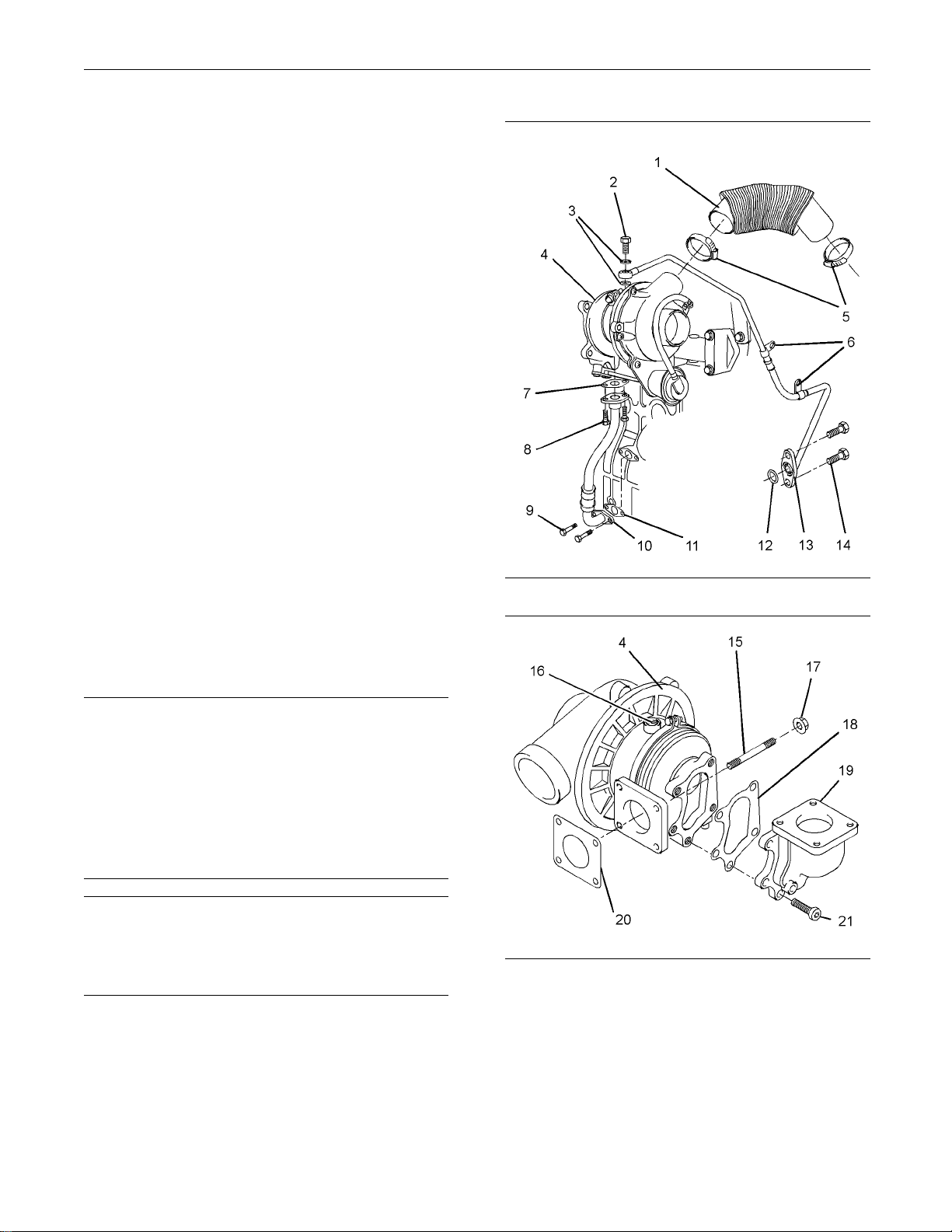
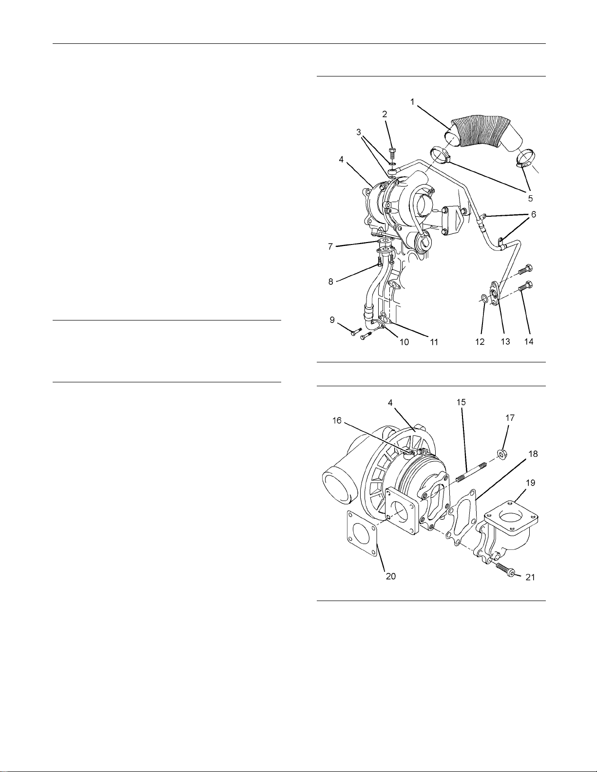
ion 21
Illustrat
Illustration 22
g01304121
g01304528
1. Loosen hose clamps (5) and remove air inlet hose
Note: Plug and cap all open ports and tube
assemblies.
(1).
2. Remove allen head screws (21) and remove
exhaust elbow (19) from turbocharger (4). Remove
gasket (18) from the turbocharger.
Page 17
KENR6226-01 17
This document has been printed from SPI². Not for Resale
Disassembly and Assembly Section
3. Remove banjo bolt (2) and washers (3). Remove
the fasteners a
tube clips (6). Remove bolts (14) and remove tube
assembly (13) from the cylinder block. Remove
O-ring seal (1
4. Remove bolts (8) and disconnect tube assembly
(10) from the
If necessary, remove bolts (9) and remove tube
assembly (10
joint (11).
nd the spacers (not shown) for
2).
turbocharger. Remove joint (7).
) from the cylinder block. Remove
5. Remove nuts (
from the exhaust manifold. Remove gasket (20)
from the exhaust manifold. If necessary, remove
studs (15) fr
Note: Do not use the actuator rod of the wastegate
to lift the t
urbocharger.
Installati
Keep all parts clean from contaminants.
Contaminants may cause rapid wear and shortened
component life.
1. Ensure that the turbocharger is clean and free
from damage. Inspect the turbocharger for
wear.Ifthe
turbocharger must be replaced.
2. Te st t he a c
to Systems Operation, Testing and Adjusting,
“Wastegate - Test” for more information. If the
actuator i
operate within the specified limits, the complete
turbocharger must be replaced.
17) and remove turbocharger (4)
om the exhaust manifold.
on procedure
NOTICE
turbocharger is worn, the complete
tuator for correct operation. Refer
s damaged or the actuator does not
Illustrat
ion 23
g01304121
Illustration 24
3. Clean the mating surfaces of the exhaust manifold.
If necessary, install studs (15) to the exhaust
manifold. Tighten the studs to a torque of 18 N·m
(13 lb ft). Install a new gasket (20) over the studs.
4. Position turbocharger (4) onto the exhaust
manifold. Install nuts (17) and tighten to a torque
of 25 N·m (18 lb ft).
Note: Do not use the actuator rod of the wastegate
to lift the turbocharger .
g01304528
Page 18
18 KENR6226-01
This document has been printed from SPI². Not for Resale
Disassembly and Assembly Section
5. Ensure that tube assemblies (10) and (13) are
clean and free f
the tube assemblies.
6. If necessary,
assembly (10) onto the cylinder block. Install bolts
(9). Tighten the bolts finger tight.
Position a new joint (7) on tube assembly (10).
Align tube assembly (10) to the bottom of the
turbocharge
finger tight.
Tighten bolt
(89lbin).
7. Lubricate th
clean engine oil through oil inlet port (16). Rotate
the shaft of the turbocharger in order to distribute
the lubrica
8. Install a new O-ring seal (12) to tube assembly
(13). Posit
cylinder block. Install bolts (14). Tighten the bolts
toatorqueof10N·m(89lbin).
9. Install new washers (3) and banjo bolt (2) to tube
assembly (13). Position tube assembly (13) onto
turbochar
tight.
rom damage. If necessary, replace
position a new joint (11) and tube
r. Install bolts (8). Tighten the bolts
s (8) and (9) to a torque of 10 N·m
e bearings of turbocharger (4) with
nt.
ion tube assembly (13) against the
ger (4). Tighten the banjo bolt finger
i02959965
Exhaust Manifold - Remove
and Install
Removal Procedure
Start By:
a. If the engine is equipped with a turbocharger,
remove the tur
and Assembly, “ Turbocharger, Remove and
Install”.
Keep all parts
Contaminants may cause rapid wear and shortened
component li
Note: The two cylinder, the three cylinder and the four
cylinder engines have different exhaust manifolds.
The removal procedure is similar for all models.
bocharger. Refer to Disassembly
NOTICE
clean from contaminants.
fe.
10. If necessa
fasteners (not shown) to tube clips (6). Torque the
fasteners to 10 N·m (89 lb in).
11. Tighten banjo bolt (2) to a torque of 18 N·m
(13 lb ft).
Note: Ensure that the tube assembly does not come
into contact with any other components.
12. Clean the mating surfaces of exhaust elbow (19).
Position a new gasket (18) and exhaust elbow (19)
on turboc
Tighten the bolts to a torque of 32 N·m (24 lb ft).
13. Ensure th
defects or restrictions. Loosely install hose clamps
(5) to air inlet hose (1). Install the air inlet hose to
the conn
and to the turbocharger. Tighten the hose clamps.
ry, install the spacer and install the
harger (4). Install allen head screws (21).
at inlet hose (1) is clean and free from
ection of the inlet manifold (not shown)
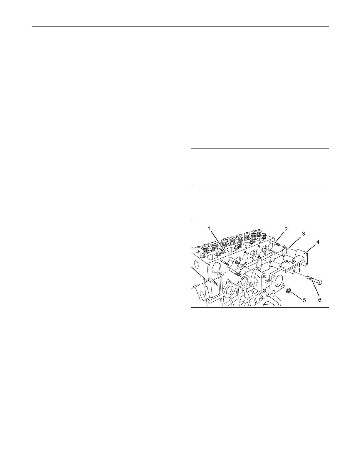
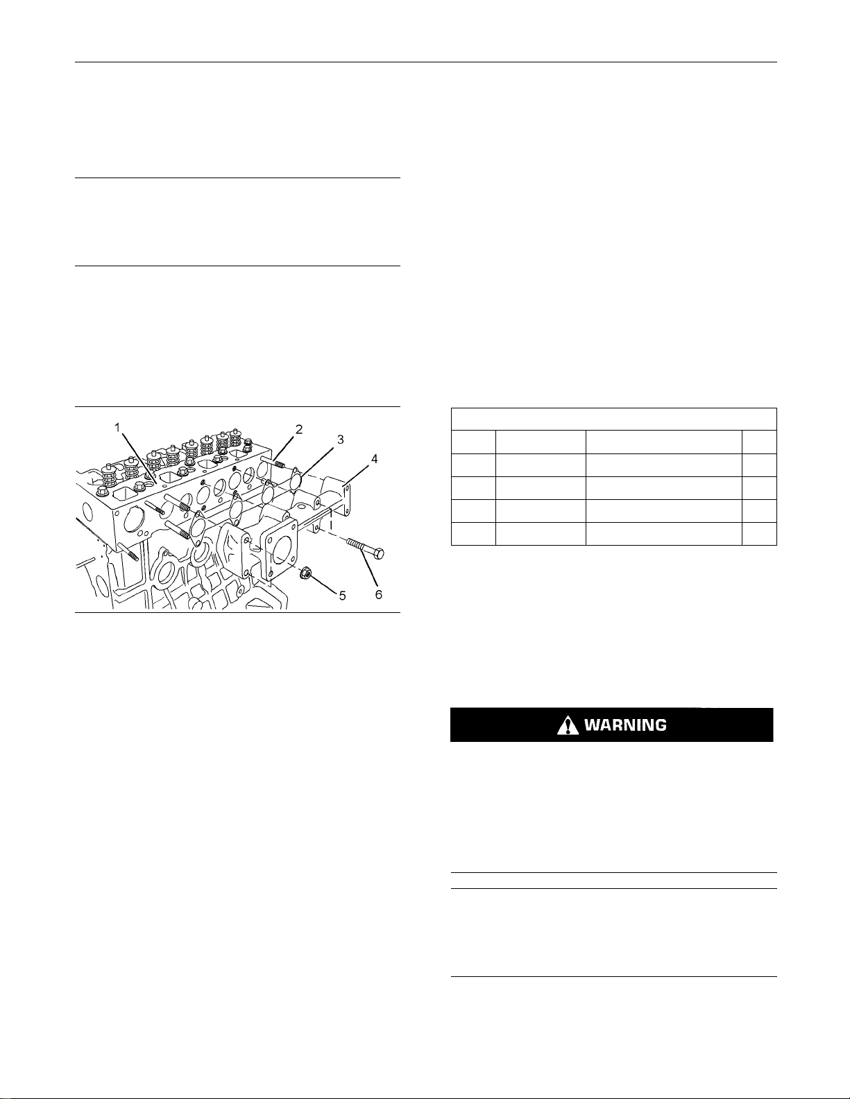
Illustration 25
Typical example
1. Loosen nuts (5) and bolts (6).
Note: In order to prevent distortion of the exhaust
manifold, loosen the outer fasteners first.
2. Remove nuts (5) and bolts (6).
Note: Identify bolts of different lengths so that the
bolts can be installed in the correct positions.
3. Remove exhaust manifold (4) from cylinder head
(1). Note the orientation of the exhaust manifold
for installation.
g01326567
4. Remove gasket (3) from cylinder head (1).
Page 19
KENR6226-01 19
This document has been printed from SPI². Not for Resale
Disassembly and Assembly Section
5. If necessary, remove exhaust manifold studs (2)
from cylinder h
Installation P
ead (1).
rocedure
NOTICE
Keep all parts c
lean from contaminants.
Contaminants may cause rapid wear and shortened
component lif
e.
Note: The two cylinder, the three cylinder and the four
cylinder engines have different exhaust manifolds.
The installation procedure is similar for all models.
1. Ensure that the mating surfaces of the cylinder
head and the exhaust manifold are clean and free
from damage.
Note: On three cylinder engines and four cylinder
engines, tight
en the inner bolts first.
End By:
a. If the engine is equipped with a turbocharger,
install the turbocharger. Refer to Disassembly and
Assembly, “ Tu
rbocharger, Remove and Install”.
i02959972
Inlet and Exhaust Valve
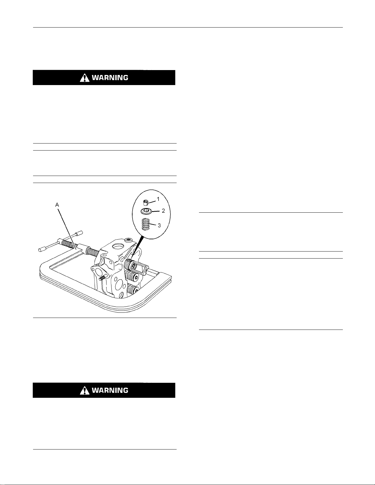
Springs - Remove an d Install
Removal Procedure
Table 3
Required Tools
Tool Part Number Part Description Qty
21825739
A
(1)
B
(2)
B
(3)
B
(1)
402D-05 and 4
(2)
403D-11 and 404D-15 engines
(3)
403D-15, 403 D-15T, 403D-17, 404D-22, 404D-22T and
404D-22TA engines
-
27610235
21825934
03D-07 engines
Val ve Sp r ing
Adapter 1
Adapter 1
Adapter 1
Compressor 1
on 26
Illustrati
Typical example
g01326567
2. If necessary, install exhaust manifold studs (2) to
cylinder head (1).
3. Install a new exhaust manifold gasket (3) to
cylinder head (1).
4. Align exhaust manifold (4) with studs (2) and
install the exhaust manifold to cylinder head (1).
Note: Ensure that the exhaust manifold is installed
in the correct orientation.
5. Install nuts (5) and bolts (6) finger tight.
Note: Ensu
re that bolts of different lengths are
installed in the correct positions.
6. For 402D-0
5, 403D-07, 403D-11, 403D-15,
403D-15T, 403D-17, and 404D-15 engines,
tighten nuts (5) and bolts (6) to a torque of 10 N·m
(89lbin)
.
For 404D-22, 404D-22T and 404D-22TA engines,
tighten n
uts (5) and bolts (6) to a torque of 25 N·m
(18 lb ft).
Start By:
a. Remove the rocker shaft assembly. Refer to
Disassembly
and Assembly, “Rocker Shaft and
Pushrod - Remove”.
Personal injury can result from being struck by
parts propelled by a released spring force.
Make sure to wear all necessary protective equipment.
Follow t he recommended procedure and use all
recommended tooling to release the spring force.
NOTICE
Keep all parts clean from contaminants.
Contaminants may cause rapid wear and shortened
component life.
Page 20
20 KENR6226-01
This document has been printed from SPI². Not for Resale
Disassembly and Assembly Section
Note: Do not use excessive force to turn the
NOTICE
Install suitable plugs to the inlet ports of the cylinder
head in order to
prevent the entry of loose parts into
the engine.
crankshaft. Th
stems.
d. Continue to ro
e use of force can result in bent valve
tate the crankshaft and gradually
release the pressure on Tooling (A) until the
piston is at the top center position. The valve
NOTICE
Plug the apertures for the push rods in the cylinder
is now held in
spring to be safely removed.
a position that allows the valve
head in order to prevent the entry of loose parts into
the engine.
Note: The removal procedure is similar for the two
Ensure that th
e valve spring is compressed squarely
or damage to the valve stem may occur.
NOTICE
cylinder, the three cylinder and the four cylinder
engines. The following procedure should be adopted
in order to remove the valve springs when the
cylinder head is installed to the engine. Refer to
Disassembly and Assembly, “Inlet and Exhaust
Valves - Remove and Install” for the procedure to
remove the valve springs from a cylinder head that
has been removed from the engine.
Note: Ensure that the appropriate piston is at the top
center position before the valve spring is removed.
Failure to ensure that the piston is at the top center
2. Use tool (A) i
Remove valve keepers (1).
Note: For fou
require replacement the procedure can be carried
out on two cylinders at the same time. The procedure
canbecarri
1with4and2with3.Ensurethatallofthevalve
springs are installed before changing from one pair
of cylinder
n order to compress valve spring (3).
r cylinder engines, if all valve springs
ed out on the following pairs of cylinders.
s to another pair of cylinders.
position may allow the valve to drop into the cylinder
bore.
NOTICE
Do not turn the crankshaft while the valve springs are
removed.
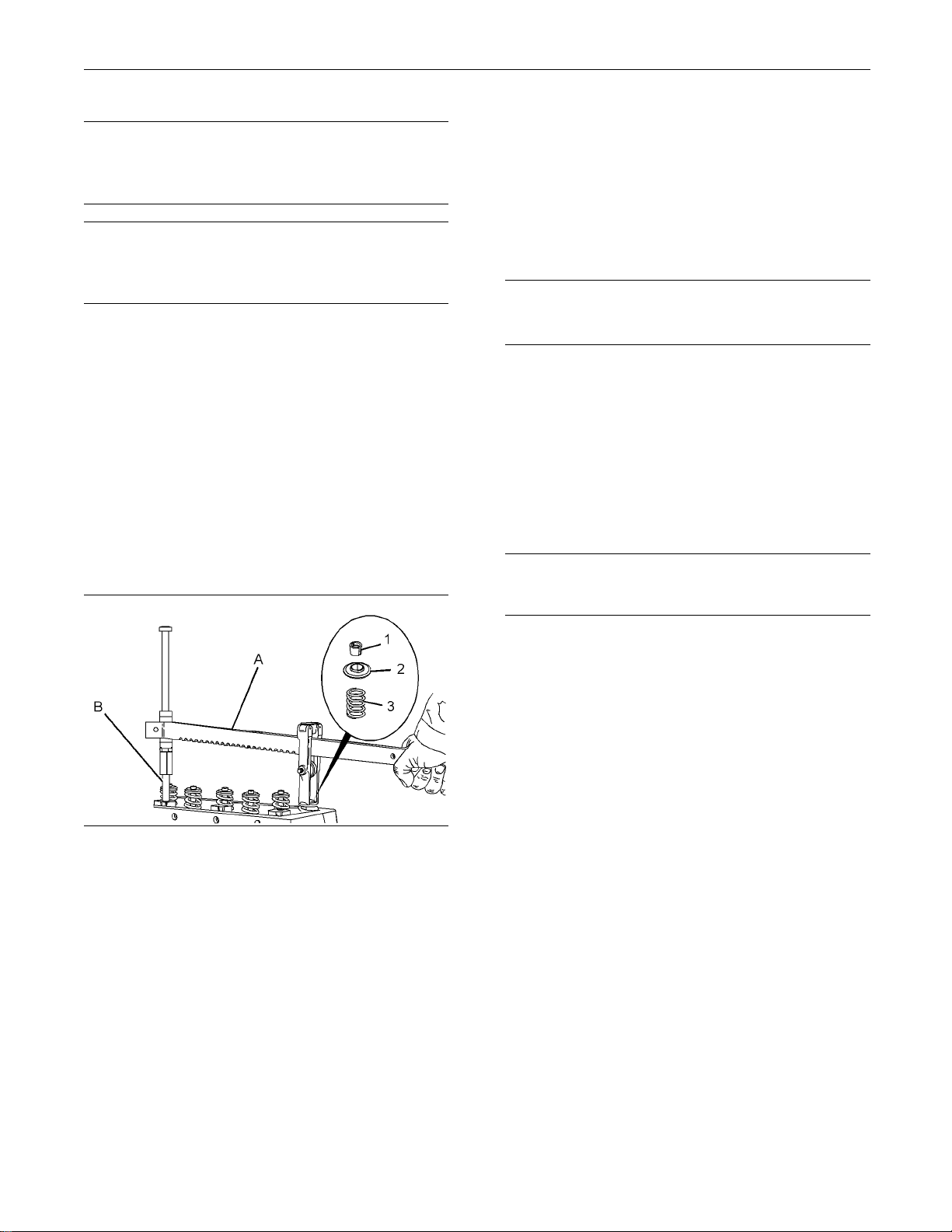
Illustration 27
Typical example
1. Follow Ste
ps 1.a through 1.d in order to position
g0130458
the appropriate piston at top center.
a. Install To
oling (A) and (B) in position on the
cylinder head in order to compress a valve
spring for the appropriate piston.
b. Use Tooling (A) in order to compress valve
spring (3) and open the valve slightly.
Note: Do not compress the spring so that the valve
spring retainer (2) touches the valve stem seal.
3. Apply sufficient pressure to Tooling (A) in order to
allow removal of the valve keepers (1).
Note: Do not compress the spring so that the valve
spring retainer (2) touches the valve stem seal.
Remove valve keepers (1).
4. Slowly rel
easethepressureonTooling(A).
5. Remove valve spring retainer (2) and remove
3
valve spri
ng (3).
6. RemoveTooling(A)and(B).
c. Carefully rotate the crankshaft until the piston
touches the valve.
Page 21
KENR6226-01 21
This document has been printed from SPI². Not for Resale
Disassembly and Assembly Section
Installation P
Table 4
Tool Part Number Part Description Qty
21825739
A
(1)
B
(2)
B
B
(1)
(2)
(3)
404D-22TA engines
27610235
(3)
21825934 Adapter 1
402D-05 and 403D-07 engines
403D-11 and 404D-15 engines
403D-15, 403D-15T, 403D-17, 404D-22, 404D-22T and
rocedure
Required Tools
-
Valve Spring Compressor 1
Adapter 1
Adapter 1
NOTICE
Keep all parts clean from contaminants.
Contaminants may cause rapid wear and shortened
component life.
NOTICE
Do not turn the crankshaft while the valve springs are
removed.
Improper assembly of parts that are spring loaded
can cause bodily injury.
T o prevent possible injury, follow the established
assembly procedure and wear protective equipment.
NOTICE
Ensure that the valve spring is compressed squarely
or damage to the valve stem may occur.
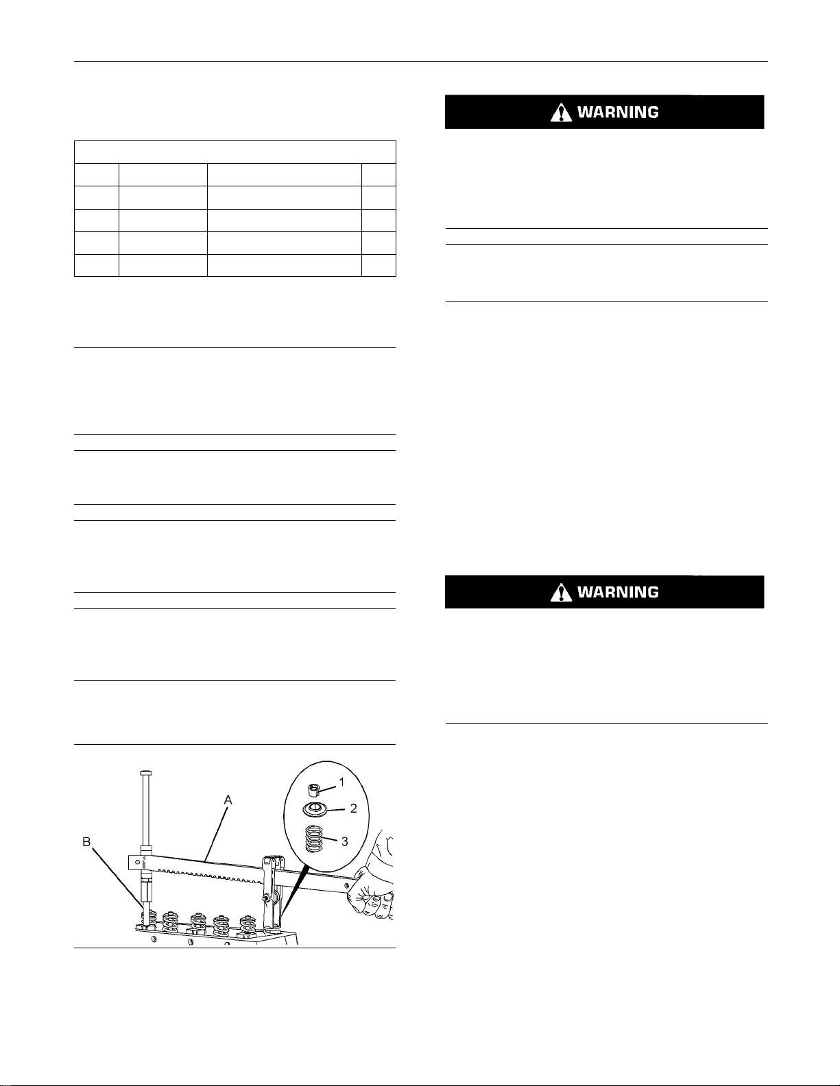
3. Install Tooling (A) and (B) in the appropriate
position on the cylinder head in order to compress
the valve spri
ng.
4. Apply sufficient pressure to Tooling (A) in order to
install valve
keepers (1).
Note: Do not compress the spring so that valve
spring retai
ner (2) touches the valve stem seal.
Install the valve spring keepers.
5. Carefully release the pressure on Tooling (A).
NOTICE
Plug the apertures for the push rods in the cylinder
head in order to prevent the entry of loose parts into
the engine.
NOTICE
Install suitable plugs to the inlet ports of the cylinder
head in order to
prevent the entry of loose parts into
the engine.
1. Inspect the val
ve springs for the correct length.
Refer to Specifications, “Cylinder Head Valves ”.
Note: Ensure
that the valve keepers are correctly
seated.
The valve spring keepers can be thrown from
the valve when the valve spring compressor is
released. E
nsure that the valve spring keepers
are properly installed on the valve s tem. To help
prevent personal injury, keep away from the front
of the valve
spring keepers and valve springs
during the installation of the valves.
6. Remove Tool
ing (A). Ensure that all of the valves
are secured in place by a valve spring and valve
keepers. Rotate the crankshaft through about
45 degrees
inordertoclearthepistonfromthe
valve. Lightly strike the top of the valve with a soft
hammer in order to ensure that the valve keepers
are proper
ly installed.
End By:
a. Install the rocker shaft assembly. Refer to
Disassembly and Assembly, “Rocker Shaft and
Pushrod -
Install”.
Illustration 28
Typical example
g01304583
2. Install valve spring (3) onto the cylinder head.
Position valve spring retainer (2) onto valve spring
(3).
Page 22
22 KENR6226-01
This document has been printed from SPI². Not for Resale
Disassembly and Assembly Section
i02959973
Inlet and Exhaust Valves Remove an d Install
Ensure that the valve spring is compressed squarely
or damage to the
NOTICE
valve stem may occur.
Removal Procedure
Table 5
Required Tools
Tool Part Number Part Description Qty
A 21825663
Start By:
a. Remove the cylinder head. Refer to Disassembly
and Assembly, “Cylinder Head - Remove”.
Valve Spring
Compressor
1
NOTICE
Keep all parts clean from contaminants.
Contaminants may cause rapid wear and shortened
component life.
Note: The removal procedure is identical for the
two cylinder, the three cylinder and the four cylinder
engines. The
Illustrations show a four cylinder engine.
1. Clean the bottom face of the cylinder head.
Check the dep
th of the valves below the face of
the cylinder h ead before the valve springs are
removed. Refer to Specifications, “Cylinder Head
Val v e s ” for
the correct dimensions.
2. Place a temporary identification mark on the
heads of the
valves in order to identify the correct
position.
Note: Do not
stamp the heads of the valves.
Stamping or punching the heads of the valves could
cause the valves to fracture.
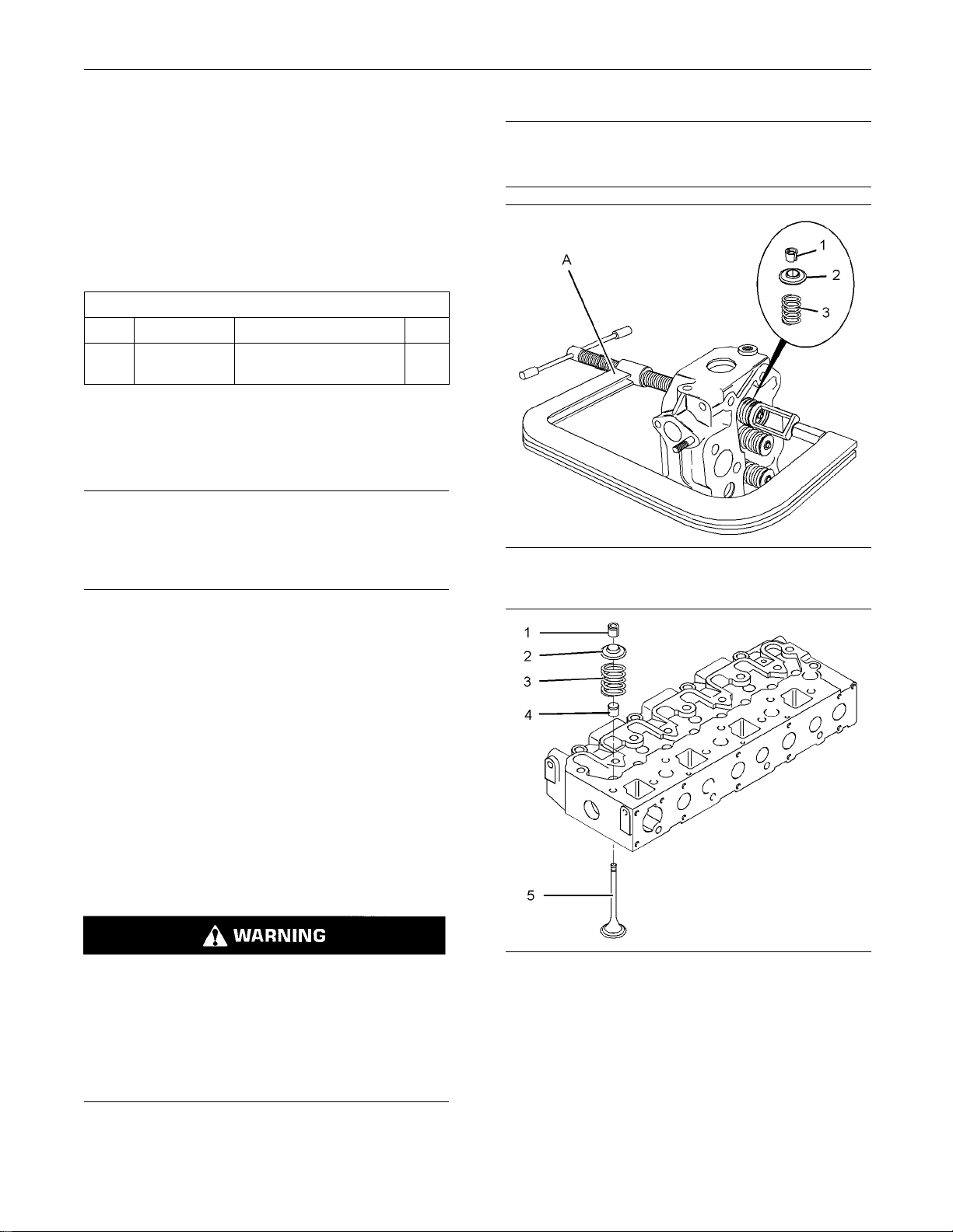
Illustration 29
Typical example
g01315963
Personal injury can result from being struck by
parts prop
elled by a released spring force.
Make sure to wear all necessary protective equipment.
Illustration 30
Typical example
3. Use Tooling (A) in order to compress the
appropriate valve spring (3). Remove valve
keepers (1).
Follow the recommended procedure and use all
recommen
ded tooling to release the spring force.
Note: Do not compress the valve spring so that valve
spring retainer (2) touches valve stem seal (4).
4. Remove Tooling (A).
g01325840
Page 23
KENR6226-01 23
This document has been printed from SPI². Not for Resale
Disassembly and Assembly Section
5. Remove valve spring retainer (2). Remove valve
spring (3).
6. Remove valve (5).
7. Remove valve stem seal (4).
8. Repeat Steps 3
Installation
Table 6
Tool Part Number Part Description Qty
21825663
A
(1)
B
B
(1)
(2)
404D-22T and 404D-22TA engines
21825622
(2)
21825623
402D-05 and 40
403D-11, 403D-15, 403D-15T, 403D-17, 404D-15, 404D -22,
to 7 for the remaining valves.
Procedure
Required Tools
Valve Spring Compressor 1
Valve Stem Seal Replacer 1
Val v e St e m Se a
3D-07 engines
l Replacer 1
NOTICE
Keep all parts clean from contaminants.
Contaminants may cause rapid wear and shortened
component life.
Note: The installation procedure is identical for the
two cylinder, the three cylinder and the four cylinder
engines. The I
llustrations show a four cylinder engine.
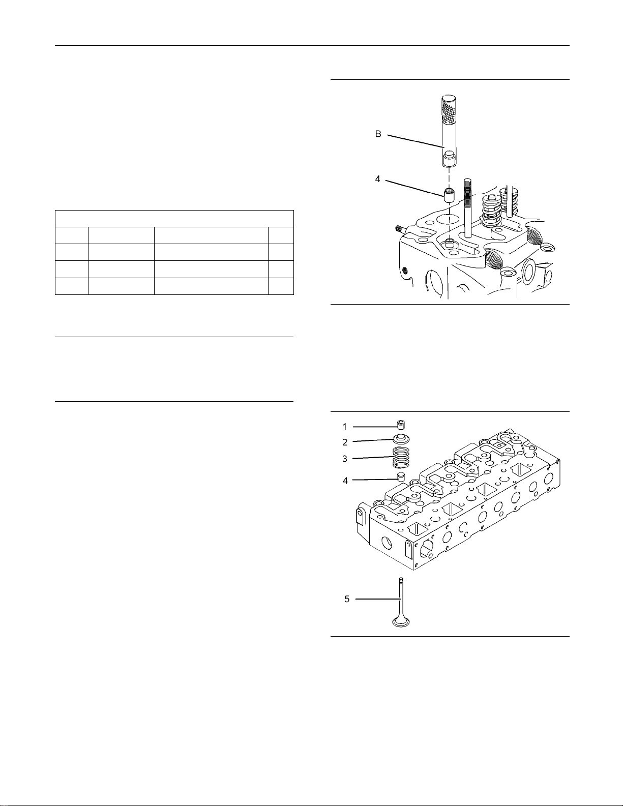
Illustration 31
Typical example
g01315893
2. Use Tooling (B) to install new valve stem seals (4)
onto each of the valve guides.
Note: The outer face of the valve guides must be
clean and dry before installing the valve stem seals.
1. Clean all components of the cylinder head
assembly. En
sure that all ports, all coolant
passages and all lubrication passages in the
cylinder head are free from debris. Follow Steps
1.a through
1.e in order to inspect the components
of the cylinder head assembly. Replace any
components that are worn or damaged.
a. Inspect the cylinder head for wear and for
damage. Refer to Systems Operation, Testing
and Adjusti
ng, “Cylinder Head Inspect”.
b. Inspect the valve seats for wear and for
damage. Ref
er to Specifications, “Cylinder
Head Valves” for further information.
c. Inspect th
e valve guides for wear and for
damage. Refer to Specifications, “Cylinder
Head Valves” and Systems Operation, Testing
and Adjust
ing, “Valve Guide - Inspect” for
further information.
d. Inspect th
e valves for wear and for damage.
Refer to Specifications, “Cylinder Head Valves”.
e. Inspect th
e valve springs for the correct length.
Refer to Specifications, “Cylinder Head Valves”.
Illustration 32
Typical example
g01325840
3. Lubricate the stem of valve (5) with clean engine
oil. Install valve (5) in the appropriate position in
the cylinder head. Check the depth of the valve
below the face of the cylinder head. Refer to
Systems Operation, Testing and Adjusting, “Valve
Depth - Inspect” for more information.
Page 24
24 KENR6226-01
This document has been printed from SPI². Not for Resale
Disassembly and Assembly Section
4. Install valve spring (3) to the cylinder head.
Position valve
(3).
Personal injury can result from being struck by
parts propel
Make sure to wear all necessary protective equipment.
Follow the recommended procedure and use all
recommended
Ensure that the valve spring is compressed squarely
or damage to the valve stem may occur.
spring retainer (2) onto valve spring
led by a released spring force.
tooling to release the spring force.
NOTICE
6. Remove Tooling (A).
7. Repeat Steps 4 to 6 for the remaining valves.
8. Place the cylin
Ensure that the heads of the valves are not
obstructed. Gently strike the top of the valves
with a soft ham
keepers (1) are properly installed.
End By:
a. Install the cylinder head. Refer to Disassembly
and Assembly
der head on a suitable support.
mer in order to ensure that valve
, “Cylinder Head - Install”.
i02959976
Engine Oil Line - Remove and
Install
Removal Procedure
NOTICE
Keep all parts clean from contaminants.
Illustration 33
Typical example
5. Use Tooling (A) in order to compress valve spring
(3). Install valve keepers (1).
Note: Donotcompressthespringsothatvalve
spring retainer (2) touches valve stem seal (4).
The valve spring keepers can be thrown from
the valve when the valve spring compressor is
released. Ensure that the valve spring keepers
are properly installed on the valve stem. To help
prevent personal injury, keep away from the front
of the valve spring keepers and valve springs
during the installation of the valves.
g01315963
Contaminants may cause rapid wear and shortened
component life.
NOTICE
Care must be taken to ensure that fluids are contained
during performance of inspection, maintenance, testing, adjusting and repair of the product. Be prepared to
collect the fluid with suitable containers before opening any compartment or disassembling any component containing fluids.
Dispose of all fluids according to local regulations and
mandates.
Page 25
KENR6226-01 25
This document has been printed from SPI². Not for Resale
Disassembly and Assembly Section
4. Remove oil line (1) from the engine.
Installation Procedure
NOTICE
Keep all parts clean from contaminants.
Contaminants may cause rapid wear and shortened
component life.
ion 34
Illustrat
Typical example
g01304820
1. Loosen nut (2) that attaches the clip on oil line (1)
to the fuel injection pump.
2. Remove banjo bolt (3) and remove washers (4)
from the cylinder block.
ion 36
Illustrat
Typical example
g01304820
1. Place oil line (1) on the engine. Ensure that the
clip on the oil line is located below nut (2).
2. Position banjo bolt (3) and new washers (4) onto
oil line (1). Install the banjo bolt and oil line to the
cylinder
block finger tight.
Illustration 35
Typical example
g01307372
3. Remove banjo bolt (5) and remove washers (6)
from the cylinder head.
Page 26
26 KENR6226-01
This document has been printed from SPI². Not for Resale
Disassembly and Assembly Section
NOTICE
Care must be taken to ensure that fluids are contained
during perform
ance of inspection, maintenance, testing, adjusting and repair of the product. Be prepared to
collect the fluid with suitable containers before opening any compar
tment or disassembling any compo-
nent containing fluids.
Illustration 37
Typical example
g01307372
3. Position banjo bolt (5) and new washers (6) onto
oil line (1). Install the banjo bolt and the oil line to
the cylinder head finger tight.
4. Tighten nut (2) that attaches the clip on oil line (1)
to the fuel injection pump.
For 402D-05, 403D-07, 403D-11 and 404D-15
engines, tighten nut (2) to a torque of 6 N·m
(53lbin).
For 403D-15, 403D-15T, 403D-17, 404D-22,
404D-22T and 404D-22TA engines, tighten nut (2)
toatorqueof15N·m(133lbin).
Dispose of all
fluids according to local regulations and
mandates.
NOTICE
Keep all parts clean from contaminants.
Contaminants may cause rapid wear and shortened
component life.
1. Drain the coolant from the cooling system into
a suitable con
tainer. Refer to Operation and
Maintenance Manual, “Cooling System Coolant Drain” for the correct procedure.
2. Drain the engine lubricating oil into a suitable
container. Refer to Operation and Maintenance
Manual, “Eng
ine Oil and Filter - Change” for the
correct procedure.
5. Tighten banjo bolts (3) and (5) to a torque of
12N·m(106lbin).
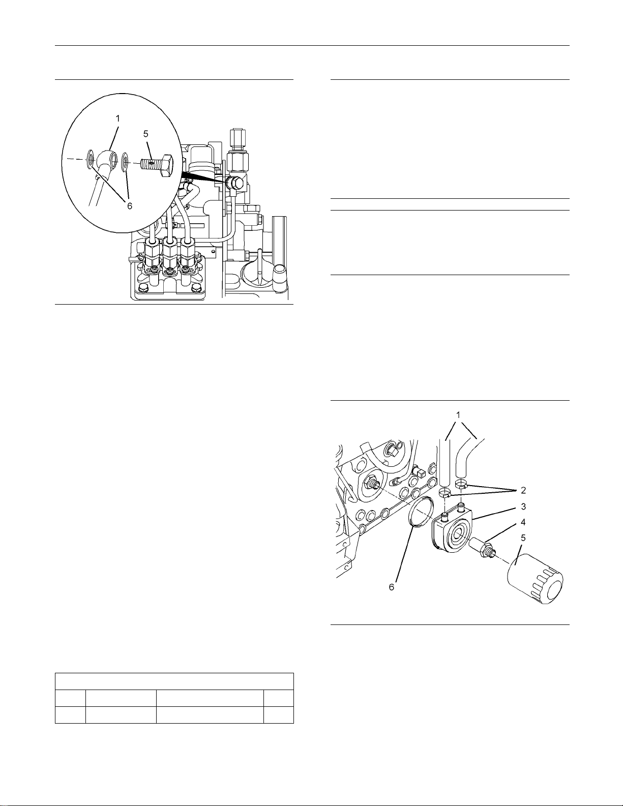
i02645673
Engine Oil Cooler - Remo ve
and Install
Illustration 38
Removal Procedure
Table 7
Required Tools
Tool Part Number Part Description
A
-
Strap Wrench
Qty
1
Typical example
3. Use Tooling (A) to remove oil filter element (5).
4. Loosen hose clamps (2) and disconnect hoses
(1). Note the positions of the coolant inlet and the
coolant outlet for installation.
5. Remove adapter (4) and remove oil cooler (3)
from the cylinder block.
g01304837
Page 27
KENR6226-01 27
This document has been printed from SPI². Not for Resale
Disassembly and Assembly Section
Note: Make a temporary mark in order to show the
orientation of
6. Remove O-ring seal (6) from oil cooler (3).
the oil cooler for installation.
Installation Procedure
NOTICE
Keep all parts clean from contaminants.
Contaminants may cause rapid wear and shortened
component life.
1. Ensure that the oil cooler is clean and free from
damage. Clean the mating surfaces of the cylinder
block.
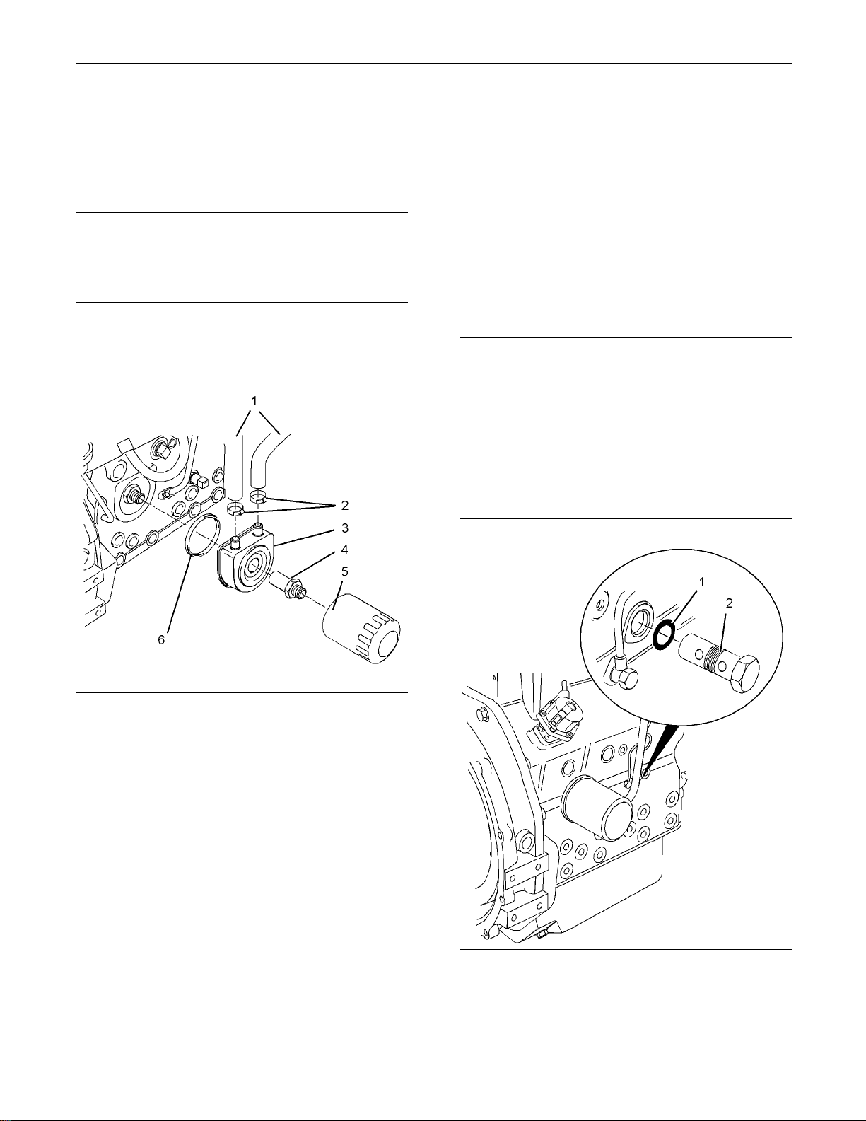
i02645679
Engine Oil Relief Valve Remove and Install
Removal Procedure
NOTICE
Keep all parts clean from contaminants.
Contaminants m
component life.
Care must be taken to ensure that fluids are contained
during performance of inspection, maintenance, testing, adjusting
collect the fluid with suitable containers before opening any compartment or disassembling any component contain
Dispose of all fluids according to local regulations and
mandates.
ay cause rapid wear and shortened
NOTICE
and repair of the product. Be prepared to
ing fluids.
Illustration 39
Typical example
2. Install a new O-ring seal (6) to oil cooler (3).
Position oil cooler (3) on the cylinder block and
install adapter (4). Tighten adapter (4) to a torque
of 34 N·m (25 lb ft).
Note: Ensure that the oil cooler is correctly oriented.
3. Connect hoses (1) to the coolant inlet and the
coolant outlet on oil cooler (3). Tighten hose
clamps (2).
4. Install a new oil filter element (5).
5. Fill the cooling system to the correct level. Refer
to Operation and Maintenance Manual, “Cooling
System Coolant - Fill” for the correct procedure.
6. Fill the engine oil pan to the correct level. Refer to
Operation and Maintenance Manual, “Engine Oil
Filter - Change” for the correct procedure.
g01304837
Illustration 40
Typical example
1. Remove engine oil relief valve (2) from the cylinder
block.
2. Remove O-ring seal (1) from engine oil relief valve
(2).
g01316066
Page 28
28 KENR6226-01
This document has been printed from SPI². Not for Resale
Disassembly and Assembly Section
Installation P
Keep all parts c
Contaminants may cause rapid wear and shortened
component life
rocedure
NOTICE
lean from contaminants.
.
i02645678
Engine Oil Pump - Remove
Removal Proced
Start By:
a. Remove the front housing. Refer to Disassembly
and Assembly, “Housing (Front) - Remove”.
Care must be taken to ensure that fluids are contained
during performance of inspection, maintenance, testing, adjustin
collect the fluid with suitable containers before opening any compartment or disassembling any component containi
Dispose of all fluids according to local regulations and
mandates.
Keep all parts clean from contaminants.
g and repair of the p roduct. Be prepared to
ng fluids.
ure
NOTICE
NOTICE
Illustration 41
Typical ex
1. Install a new O-ring seal (1) to engine oil relief
2. Lubricate engine oil relief valve (2) with clean
3. Install engine oil relief valve (2) into the cylinder
ample
valve (2).
engine oil
block. Ti
torque of 64 N·m (47 lb ft).
.
ghten the engine oil relief valve to a
g01316066
Contaminants may cause rapid wear and shortened
component life.
NOTICE
If the front housing is not installed, do not turn the
crankshaft. Damage to the engine may occur.
Engine Oil Pump
Illustration 42
g01304840
Page 29
KENR6226-01 29
This document has been printed from SPI². Not for Resale
Disassembly and Assembly Section
Idler Hub
Personal injury can result from being struck by
parts propelled by a released spring force.
Make sure to wear all necessary protective equipment.
Follow the recommended procedure and use all
recommended tooling to release the spring force.
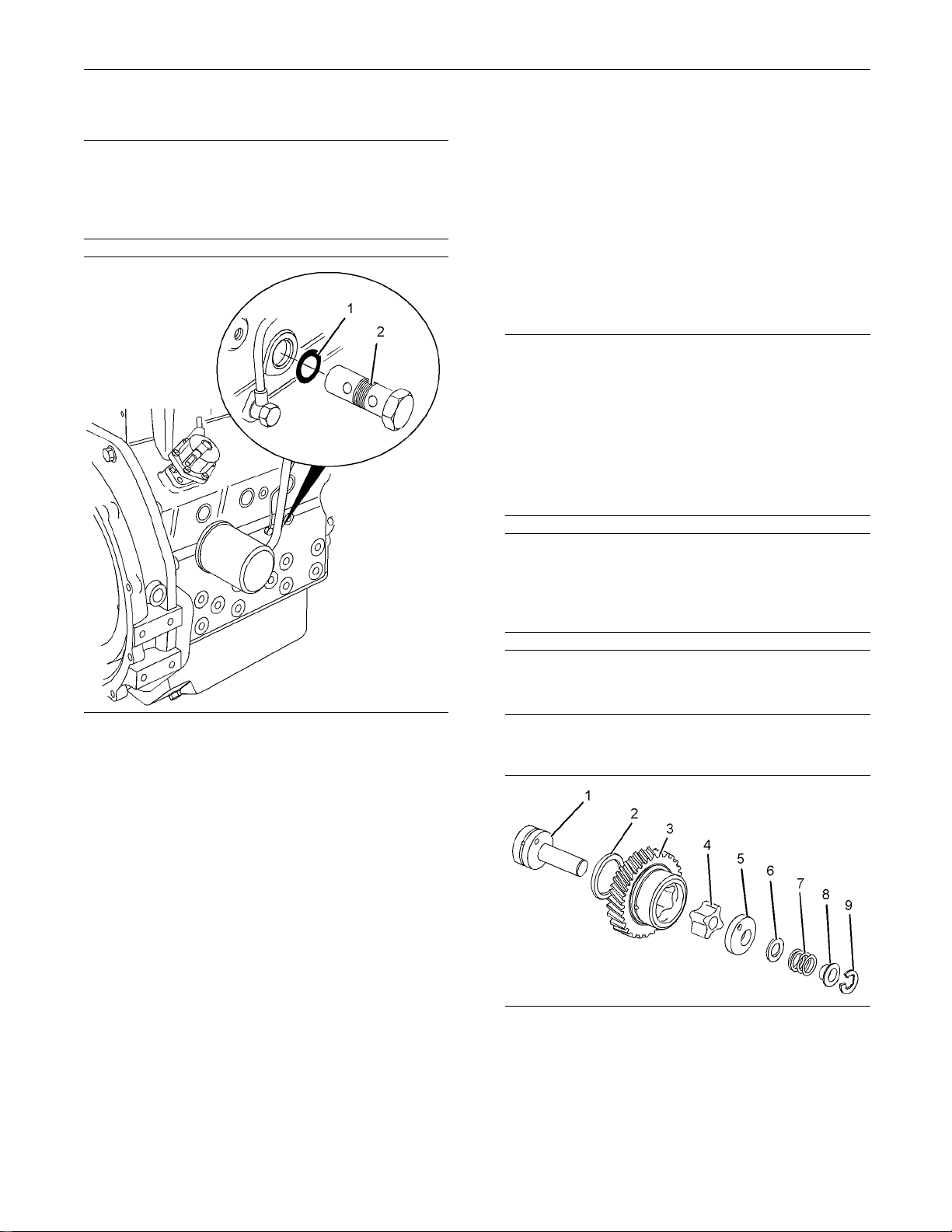
1. Remove C-clip (9) that retains idler gear (3) on
idler hub (1).
2. Remove the following items from idler hub (1):
Collar (8 )
•
Spring (7)
•
Shim (6)
•
Oil pump cover (5)
•
3. Remove idler gear (3) from idler hub (1).
4. Remove inner rotor (4) from idler hub (1).
5. Remove thrust washer (2) from idler hub (1).
6. In order to remove the suction pipe, follow Steps
6.a through 6.d .
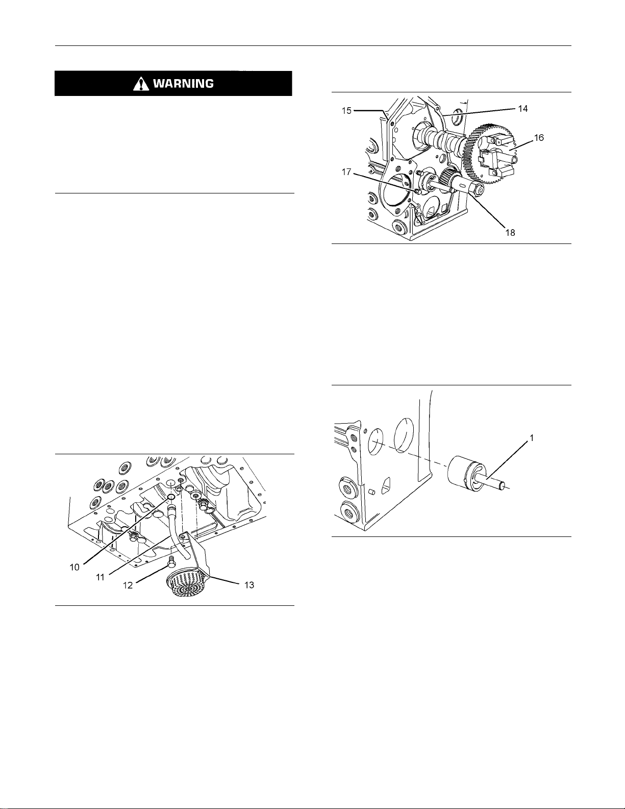
Illustration 44
Typical example
1. Remove camsh
aft (16). Refer to Disassembly and
Assembly, “Camshaft - Remove”.
2. Remove bolts
(17) and plate (14) from the cylinder
block. Remove joint (15).
3. Remove crank
shaft (18). Refer to Disassembly
and Assembly, “Crankshaft - Remove”.
g01320621
Illustration 45
Typical example
4. Use a hammer and use a suitable drift to remove
idler hub (1) from the cylinder block. Align the drift
to the rear face of the hub and drive the hub from
the inside of the cylinder block outward.
Illustration 43
g01327023
a. Removetheengineoilpan.Referto
Disassembly and Assembly, “Engine Oil Pan Remove and
Install”.
b. Remove bolts (12) and oil strainer (13) from
the cylind
er block. Inspect the oil strainer for
damage. If the oil strainer is damaged, use a
new part for replacement.
c. Remove suction pipe (11) from the cylinder
block.
d. Remove O-ring seal (10) from the suction pipe.
g01311490
Page 30
30 KENR6226-01
This document has been printed from SPI². Not for Resale
Disassembly and Assembly Section
i02960005
Engine Oil Pump - Install
Installation P
Table 8
Tool Part Number Part Description Qty
(1)
A
(2)
A
(3)
A
B
(1)
402D-05 and 403D-07 engines
(2)
403D-11 and 404D-15 engines
(3)
403D-15, 403D-15T, 403D-17, 404D-22, 404D-22T and
404D-22TA engines
Keep all parts clean from contaminants.
Contaminants may cause rapid wear and shortened
component life.
If the front housing is not installed, do not turn the
crankshaft. Da
21825624
21825625
27610324 Alignment Tool 1
rocedure
Required Tools
Alignment Tool 1
Alignment Tool 1
-
mage to the engine may occur.
Multipurpose Grease 1
NOTICE
NOTICE
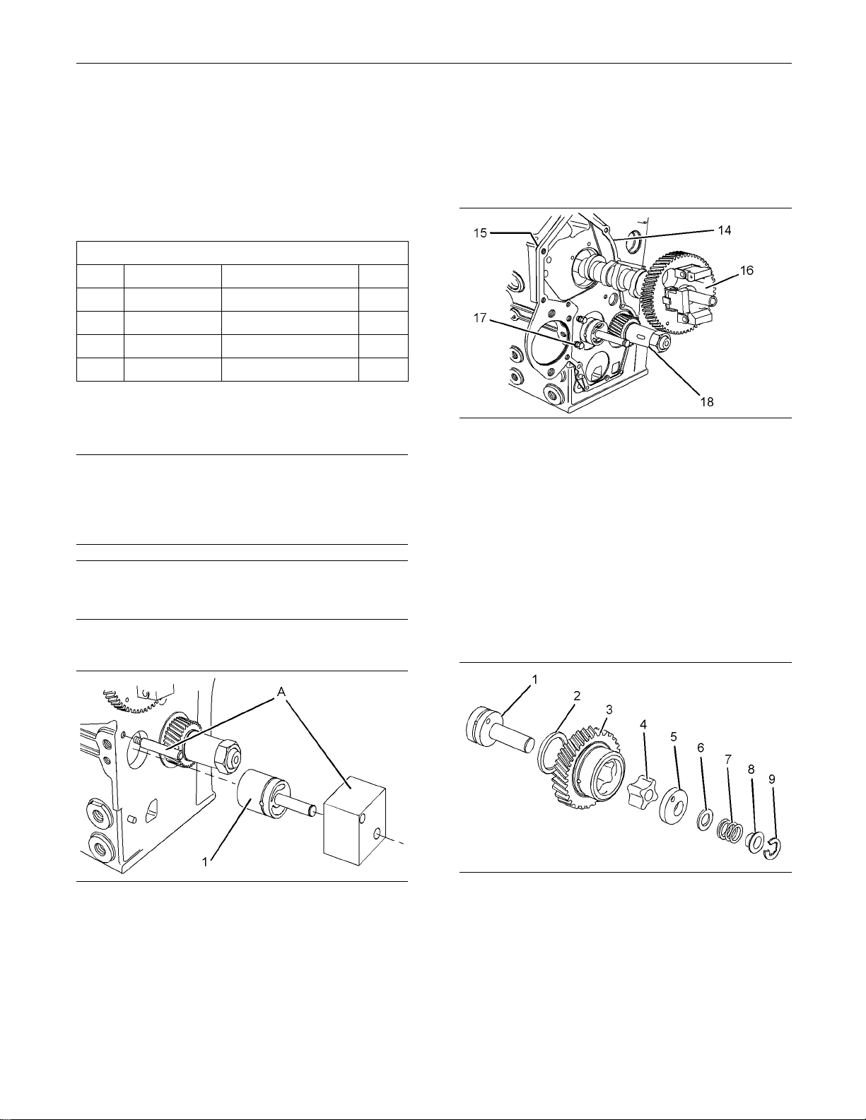
3. Use a hammer in order to strike the guide plate of
To o li ng ( A) . D r
ive idler hub (1) into the cylinder
block until the guide plate contacts the front of the
cylinder block.
4. Remove Tooling (A).
Illustration 47
g01320621
5. Install crankshaft (18). Refer to Disassembly and
Assembly, “Crankshaft - Install”.
6. Position a new joint (15) on the cylinder block.
Align plate (14) with the dowels in the cylinder
block and install the plate. Install bolts (17) and
tightentoatorqueof10N·m(89lbin).
7. Install camshaft (18). Refer to Disassembly and
Assembly, “Camshaft - Install”.
Idler Hub
Illustration 46
Typical example
1. Install the p
in of Tooling (A) to the cylinder block.
2. Install idler hub (1) into the guide plate of Tooling
(A). Align th
e guide plate of Tooling (A) with pin
of Tooling (A).
g01305803
Engine Oil Pump
Illustration 48
Typical example
1. Install thrust washer (2). Lubricate the thrust
washer with clean engine oil.
g01304840
Page 31

KENR6226-01 31
This document has been printed from SPI². Not for Resale
Disassembly and Assembly Section
Collar (8)
•
Refer to Illustration 48.
Illustration 49
Typical example
g01305805
Improper assembly of parts that a re spring loaded
can cause bodily injury.
To prevent possible injury, follow the established
assembly procedure and wear protective equipment.
6. Install retain
Illustration 50
Checking end play by using a feeler gauge
ing ring (9) on idler hub (1).
g01320625
7. Use a feeler gauge in order to measure the
end play of the engine oil pump. Refer to
Specifications, “Engine Oil Pump”.
8. If the oil strainer was removed, follow Steps 8.a
through 8.c in order to install the oil strainer.
2. Apply Tooling (B) to the faces of inner rotor (4)
and to the vanes of idler gear (3).
3. Align timing marks (X) on idler gear (3) with the
respective timing marks on gears (19) and (20).
Install idler gear (3) onto idler hub (1).
4. Install inner rotor (4) to idler gear (3).
Personal injury can result from the release of the
spring force.
The drive shaft, the piston, and the drive gear are
under spring force.
Use a press to slowly release the spring force before the components are removed.
5. Install the following items to idler hub (1):
Oil pump cover (5)
•
Shim (6)
•
Spring (7)
•
Illustrat
ion 51
g01327023
a. Install a new O-ring seal (10) on oil tube
assembly (
11).
b. Install oil suction pipe (11) in the cylinder block.
c. Install oil strainer (13) to the cylinder block
and tighten bolts (12) to a torque of 11 N·m
(97lbin)
.
End By:
a. Install the front housing. Refer to Disassembly and
Assembly, “Housing (Front) - Install”.
b. Install the engine oil pan. Refer to Disassembly
and Assembly, “Engine Oil Pan - Remove and
.
Install”
Page 32

32 KENR6226-01
This document has been printed from SPI². Not for Resale
Disassembly and Assembly Section
i02960013
Water Pump - Remove and
Install
(403D-11, 403D
-15, 403D-15T,
403D-17, 404D-15, 404D-22,
404D-22T and 404D-22TA
Engines)
Removal Procedure
Start By:
a. Remove the fa
Assembly, “Fan - Remove and Install”.
b. Remove the al
Assembly, “Alternator - Remove and Install”.
Keep all part
Contaminants may cause rapid wear and shortened
component li
Care must be t
during performance of inspection, maintenance, testing, adjusting and repair of the product. Be prepared to
collect the
ing any compartment or disassembling any component containing fluids.
Dispose of all fluids according to local regulations and
mandates.
1. Drain the co
suitable container for storage or disposal. Refer
to Operation and Maintenance Manual, “Cooling
System Coo
fluid with suitable containers before open-
n. Refer to Disassembly and
ternator. Refer to Disassembly and
NOTICE
s clean from contaminants.
fe.
NOTICE
aken to ensure that fl uids are contained
olant from the cooling system into a
lant - Drain” for more information.
Illustration 52
Typical example
Illustration 53
Typical example
3. Loosen hose clamps (5) and remove hose (6)
from water pump (1).
4. Remove bolt (3) and alternator bracket (2) from
water pump (1).
g01304930
g01305206
2. Loosen the hose clamp and disconnect the hose
(not shown
)fromthewaterpumpinlet.
Note: The alternator bracket on some engines is
secured by two bolts.
5. Remove fasteners (7) and remove water pump (1).
Note: If necessary, gently tap the water pump with a
soft faced hammer in order to loosen the water pump.
6. Remove joint (4) from the cylinder block.
Page 33

KENR6226-01 33
This document has been printed from SPI². Not for Resale
Disassembly and Assembly Section
Installation P
Keep all parts c
Contaminants may cause rapid wear and shortened
component life
1. Ensure that the mating surfaces of the water pump
and the cylinder block are clean and free from
damage.
Illustration 54
Typical example
rocedure
NOTICE
lean from contaminants.
.
g01304930
Note: The alternator bracket on some engines is
secured by two b
5. For engines that have an alternator bracket that
is secured by o
torque of 10 N·m (89 lb in).
For engines th
secured by two bolts, tighten fasteners (3) and (7)
toatorqueof10N·m(89lbin).
6. Connect the hose (not shown) to the water pump
inlet and tighten the hose clamp. Install hose (6)
on the water p
7. Fill the cooling system with coolant. Refer to
Operation an
System Coolant - Fill” for the correct procedure.
End By:
a. Install the alternator. Refer to Disassembly and
Assembly, “
b. Install the fan. Refer to Disassembly and
Assembly, “
olts.
ne bolt, tighten fasteners (7) to a
at have an alternator bracket that is
ump and tighten hose clamps (5).
d Maintenance Manual, “Cooling
Alternator - Remove and Install”.
Fan - Remove and Install”.
i02645778
Water Pump - Remove and
Install
Illustration 55
Typical example
2. Install a new joint (4) to the cylinder block.
3. Place water pump (1) in position and install
fasteners (7) finger tight.
4. Position alternator bracket (2) on the water pump.
Install bolt (3) finger tight.
g01305206
(402D-05 and 403D-07 Engines)
Removal Procedure
Start By:
a. Remove the fan. Refer to Disassembly and
Assembly, “Fan - Remove and Install”.
b. Remove the alternator. Refer to Disassembly and
Assembly, “Alternator - Remove and Install”.
NOTICE
Keep all parts clean from contaminants.
Contaminants may cause rapid wear and shortened
component life.
Page 34

34 KENR6226-01
This document has been printed from SPI². Not for Resale
Disassembly and Assembly Section
3. Remove bolt (3) and remove adjusting link (2) for
NOTICE
the alternator
from water pump (1).
Care must be taken to ensure that fluids are contained
during perform
ance of inspection, maintenance, test-
ing, adjusting and repair of the product. Be prepared to
Note: On some engines, the adjusting link for the
alternator is
secured by two bolts.
collect the fluid with suitable containers before opening any compar
tment or disassembling any compo-
4. Remove fasteners (7) and remove water pump (1).
nent containing fluids.
Note: If necessary, gently tap the water pump with a
Dispose of all
fluids according to local regulations and
soft faced hammer in order to loosen the water pump.
mandates.
5. Remove joint (6) from the cylinder head.
1. Drain the coolant from the cooling system into a
suitable cont
ainer for storage or disposal. Refer
to Operation and Maintenance Manual, “Cooling
System Coolant - Drain” for more information.
2. Loosen the hose clamp and disconnect the hose
(not shown) from the water pump inlet.
Illustration 56
Typical example
g01304930
If the water pu
mp has a spacer, remove spacer
(5), and remove joint (4).
Installation Procedure
NOTICE
Keep all parts clean from contaminants.
Contaminants
component life.
1. Ensure that the mating surfaces of the water pump
and the cylinder block are clean and free from
damage. If the water pump has a spacer, ensure
that the mating surfaces of the spacer are clean
and free from damage.
may cause rapid wear and shortened
Illustration 58
Typical example
Illustration 57
Typical example
g01308309
g01304930
Page 35

KENR6226-01 35
This document has been printed from SPI². Not for Resale
Disassembly and Assembly Section
i02645789
Water Temperature Regulator
Housing - Remo ve and Install
Removal Procedure
NOTICE
Keep all parts clean from contaminants.
Illustration 59
Typical example
2. Install a new joint (6) to the cylinder head.
If the water pump has a spacer, install spacer (5)
and install a new joint (4) to the cylinder head.
3. Place water pump (1) in position and install
fasteners (7). Tighten the fasteners finger tight.
4. Position adjusting link (2) for the alternator on the
water pump. Install bolt (3) finger tight.
Note: On some engines, the adjusting link for the
alternator is secured by two bolts.
5. If the adjusting link for the alternator is secured
by one bolt, tighten fasteners (7) to a torque of
10 N·m (89 lb in).
g01308309
Contaminants m
component life.
Care must be taken to ensure that fluids are contained
during performance of inspection, maintenance, testing, adjusting
collect the fluid with suitable containers before opening any compartment or disassembling any component contain
Dispose of all fluids according to local regulations and
mandates.
1. Drain the coolant from the cooling system into a
suitable container for storage or disposal. Refer
to Operation
System Coolant - Drain” for more information.
ay cause rapid wear and shortened
NOTICE
and repair of the product. Be prepared to
ing fluids.
and Maintenance Manual, “Cooling
If the adjusting link for the alternator is secured by
two bolts, tighten fasteners (3) and (7) to a torque
of 10 N·m (89 lb in).
6. Connect the hose (not shown) to the water pump
inlet and tighten the hose clamp.
7. Fill the cooling system with coolant. Refer to
Operation and Maintenance Manual, “Cooling
System Coolant - Fill” for the correct procedure.
End By:
a. Install the alternator. Refer to Disassembly and
Assembly, “Alternator - Remove and Install”.
b. Install the fan. Refer to Disassembly and
Assembly, “Fan - Remove and Install”.
Illustration 60
Typical example
2. Loosen hose clamps (5) and disconnect hose (6)
from water temperature regulator housing (2).
3. Remove bolts (4) and nuts (3).
4. Remove water temperature regulator housing (2)
from the cylinder head.
5. Remove joint (1) from the cylinder head.
g01307377
Page 36

36 KENR6226-01
This document has been printed from SPI². Not for Resale
Disassembly and Assembly Section
6. If necessary, remove the water temperature
regulator. Ref
“ Water Temperature Regulator - Remove and
Install”.
er to Disassembly and Assembly ,
Installation Procedure
NOTICE
Keep all parts clean from contaminants.
Contaminants may cause rapid wear and shortened
component life.
1. Ensure that the mating surfaces of the cylinder
head and the water temperature regulator housing
are clean and free from damage.
i02645783
Water Temperature Regulator Remove and Install
(402D-05 and 4 0
Removal Procedure
Keep all parts clean from contaminants.
Contaminants may cause rapid wear and shortened
component life.
Care must be taken to ensure that fluids are contained
during perform
ing, adjusting and repair of the product. Be prepared to
collect the fluid with suitable containers before opening any compar
nent containing fluids.
Dispose of all
mandates.
ance of inspection, maintenance, test-
tment or disassembling any compo-
fluids according to local regulations and
4D-07 Engines)
NOTICE
NOTICE
Illustration 61
Typical exa
2. Install a new joint (1) to the cylinder head.
3. Install water temperature regulator housing (2) to
4. Install bolts (4) and nuts (3). Tighten the fasteners
5. Connect hose (6) to water temperature regulator
6. If necessary, install the water temperature
7. Fill the co
mple
the cylinder head.
toatorqueof10N·m(89lbin).
housing (2). Tighten hose clamps (5).
regulator. Refer to Disassembly and Assembly ,
“WaterTem
Install”.
Operation and Maintenance Manual, “Cooling
System Coolant - Fill” for the correct procedure.
perature Regulator - Remove and
oling system with coolant. Refer to
g01307377
1. Drain the coolant from the cooling system into a
suitable con
to Operation and Maintenance Manual, “Cooling
System Coolant - Drain” for more information.
Illustration 62
Typical example
tainer for storage or disposal. Refer
g01327025
Page 37

KENR6226-01 37
This document has been printed from SPI². Not for Resale
Disassembly and Assembly Section
Personal injury can result from parts and/or covers under spring pressure.
Spring force will be released when covers are removed.
Be prepared to hold spring loaded covers as the
bolts are loosened.
2. Remove bolts (6) and nuts (5).
3. Remove outlet connection (4).
4. Remove joint (3).
5. Remove water temperature regulator (2) and
spring (1).
Installation Procedure
NOTICE
Keep all parts clean from contaminants.
Contaminants may cause rapid wear and shortened
component life.
1. Inspect the water temperature regulator for
wear, damage and correct operation. Refer
to Systems Op
“Water Temperature Regulator - Test” for more
information. If necessary, replace the water
temperatur
2. Ensure that the mating surfaces of the outlet
connection
free from damage.
eration,Testing and Adjusting,
e regulator.
and the cylinder head are clean and
Illustration 63
Typical example
Personal injury can result from parts and/or covers under spring pressure.
Spring force will be released when covers are removed.
Be prepared to hold spring loaded covers as the
bolts are loosened.
3. Install spring (1) and water temperature regulator
(2) to the cylinder head. Ensure that jiggle pin
(7) on water temperature regulator (2) is in the
vertically upward position.
4. Install a new joint (3) to the cylinder head.
5. Position outlet connection (4) onto the cylinder
head. Install nut (5) and bolts (6) to outlet
connection (4). Tighten the fasteners to a torque
of8N·m(71lbin).
g01326174
6. Fill the cooling system with coolant to the correct
level. Refer to Operation and Maintenance
Manual, “Cooling System Coolant - Fill” for more
information.
Page 38

38 KENR6226-01
This document has been printed from SPI². Not for Resale
Disassembly and Assembly Section
i02960059
Water Temperature Regula tor Remove an d Install
(403D-11, 403D
-15, 403D-15T,
403D-17, 404D-15, 404D-22,
404D-22T and 404D-22TA
Engines)
Removal Procedure
NOTICE
Keep all parts clean from contaminants.
Contaminants may cause rapid wear and shortened
component life.
NOTICE
Care must be taken to ensure that fluids are contained
during perfo
ing, adjusting and repair of the product. Be prepared to
collect the fluid with suitable containers before opening any compa
nent containing fluids.
Dispose of al
mandates.
1. Drain the coolant from the cooling system into a
suitable co
to Operation and Maintenance Manual, “Cooling
System Coolant - Drain” for more information.
rmance of inspection, maintenance, test-
rtment or disassembling any compo-
l fluids according to local regulations and
ntainer for storage or disposal. Refer
Illustration 64
Typical example
2. Remove fasteners (1).
3. Remove outlet connection (2).
Note: Identify the orientation of the outlet connection
for installation.
4. Remove joint (3).
5. Remove water temperature regulator (4) from
water temperature regulator housing (5).
Installation Procedure
g01327027
NOTICE
Keep all parts clean from contaminants.
Contaminants may cause rapid wear and shortened
component life.
1. Inspect the water temperature regulator for
wear, damage and correct operation. Refer
to Systems Operation,Testing and Adjusting,
“Water Temperature Regulator - Test” for more
information. If necessary, replace the water
temperature regulator.
2. Ensure that the mating surfaces of the outlet
connection and the water temperature regulator
housing are clean and free from damage.
Page 39

KENR6226-01 39
This document has been printed from SPI². Not for Resale
Disassembly and Assembly Section
i02645699
Flywheel - Remove
Illustration 65
Typical example
g01327027
3. Install water temperature regulator (4) to water
temperature regulator housing (5). Refer to
Specifications, “Water Temperature Regulator
Housing for 403D-11, 403D-15, 403D-15T,
403D-17, 404D-15, 404D-22, 404D-22T and
404D-22TA Engines” for the correct orientation of
the water temperature regulator.
4. Install a new joint (3).
5. Install outlet connection (2) to water temperature
regulator housing (5).
Removal Proced
Table 9
Too l
A
B
Part
Number
-
-
ure
Required Tools
Part Description
Lifting Bracket
Guide Stud
(M10 x 1.25 mm by
80mm)
Qty
1
2
Start By:
a. Remove the electric starting motor. Refer to
Disassembly and Assembly, “Electric Starting
Motor - Remove and Install”.
NOTICE
Keep all parts clean from contaminants.
Contaminants may cause rapid wear and shortened
component life.
Note: The two
cylinder, the three cylinder and the
four cylinder engines have different flywheels. The
removal procedure is similar for all models.
Note: Ensure the correct orientation of the outlet
connection.
6. Install fasteners (1).
For 403D-11 and 404D-15 engines, tighten the
fasteners to a torque of 6 N·m (53 lb in).
For 403D-15, 403D-15T, 403D-17, 404D-22,
404D-22T and 404D-22TA engines, tighten the
fasteners to a torque of 14 N·m (124 lb in).
7. Fill the cooling system with coolant to the correct
level. Refer to Operation and Maintenance
Manual, “Cooling System Coolant -Fill” for more
information.
Illustration 66
Typical example
g01305297
1. Install Tooling (A) and a suitable lifting device
to flywheel (2). The weight of the flywheel is
approximately 42 kg (93 lb).
Page 40

40 KENR6226-01
This document has been printed from SPI². Not for Resale
Disassembly and Assembly Section
2. Remove two bolts (1) from positions (X) on the
flywheel.
3. Install Tooling (B) in positions (X) on the flywheel.
4. Remove the remaining bolts (1) and remove
flywheel (2).
Note: On some three cylinder engines, a roll pin is
located between the crankshaft and the flywheel.
5. Inspect ring gear (3) and flywheel (2) for wear or
damage. If the ring gear or the flywheel is worn or
damaged, use
new parts for replacement.
Flywheel - Install
Installation P
Table 10
Too l
A
B
Keep all parts clean from contaminants.
Contaminants
component life.
Part
Number
rocedure
Required Tools
Part Description
-
-
may cause rapid wear and shortened
Lifting Bracket
Guide Stud
(M10 x 1 .25 mm by
80mm)
NOTICE
i02645696
Qty
1
2
Illustration 67
Typical example
g00825639
6. To remove ring gear (3) from flywheel (2), place
the flywheel on a suitable support. Use a hammer
(not shown) and a punch (4) in order to remove
the ring gear from the flywheel.
Always wear pr
otective gloves when handling
parts that have been heated.
Illustration 68
Typical exam
ple
g01305341
1. If the ring gear was removed, follow Steps 1.a
through 1.c
in order to install ring gear (3) to
flywheel (2).
a. Identify th
e orientation of the new ring gear in
order to install the ring gear correctly onto the
flywheel.
Note: The chamfered side of gear teeth (Y) must
face toward the starting motor when the flywheel is
installed.
This will ensure the correct engagement of
the starting motor.
Page 41

KENR6226-01 41
This document has been printed from SPI². Not for Resale
Disassembly and Assembly Section
b. Heat ring gear (3) in an oven to a maximum
temperature of
installation.
Note: Do not us
c. Ensure that the orientation of ring gear (3) is
correct and qu
flywheel (2).
150°C (302°F) prior to
e a torch to heat the ring gear.
ickly install the ring gear onto
9. Remove Tooling (A) and the lifting device from the
flywheel.
End By:
a. Install the electric starting motor. Refer to
Disassembly and Assembly, “Electric Starting
Motor-Remove
Crankshaft Re
and Install”.
i02960085
ar Seal - Remove
and Install
Removal Proc
Start By:
a. Remove the flywheel. Refer to Disassembly and
Assembly, “Flywheel - Remove”.
Keep all parts clean from contaminants.
edure
NOTICE
Illustration 69
Typical example
2. Thoroughly clean the flywheel housing. Inspect
the crankshaft rear seal for leaks. If there are any
oil leaks replace the crankshaft rear seal. Refer
to Disassembly and Assembly, “Crankshaft Rear
Seal - Remove and Install”.
3. Install Tooling (B) to positions (X) in the crankshaft.
4. Install Tooling (A) and a suitable lifting device
to flywheel (2). The weight of the flywheel is
approximately 42 kg (93 lb).
5. Position flywheel (2) onto Tooling (B).
On three cylinder engines that have a roll pin,
ensure that the roll pin is installed to the crankshaft
and that the roll pin is free from d amage. Align
theholeintheflywheel with the roll pin in the
crankshaft.
6. Install bolts (1) finger tight.
g01305297
Contaminant
component life.
Care must be taken to ensure that fluids are contained
during performance of inspection, maintenance, testing, adjusti
collect the fluid with suitable containers before opening any compartment or disassembling any component contai
Dispose of all fluids according to local regulations and
mandates.
Note: The two cylinder, the three cylinder and the
four cylinder engines have different configurations for
the flywheel
process is similar for all models.
s may cause rapid wear and shortened
NOTICE
ng and repair of the product. Be prepared to
ning fluids.
housing and the back plate. The removal
7. Remove Tooling (B) and install the two remaining
bolts (1).
8. Use a suitable tool to prevent flywheel (2) from
rotating. Tighten bolts (1) to a torque of 74 N·m
(54 lb ft).
Page 42

42 KENR6226-01
This document has been printed from SPI². Not for Resale
Disassembly and Assembly Section
Illustration 70
Typical example
g01305376
1. Remove bolts (3) and remove the flywheel housing
or back plate (2) from the cylinder block. Refer to
Disassembly and Assembly, “Flywheel Housing Remove and Install” for more information.
2. Remove crankshaft rear seal (1) from the cylinder
block. Discard the crankshaft oil seal.
Installation Procedure
Table 11
Required Tools
Tool Part Number Part Description
A
21826038
POWERPART
Silicone Adhesive
NOTICE
Keep all parts clean from contaminants.
Contaminants may cause rapid wear and shortened
component life.
Qty
1
Illustration 71
Typical example
g01305365
1. Ensure that the mating surface of cylinder block
(5) and the flywheel housing or back plate (2) are
clean and free from damage. Inspect dowels (4).
If the dowels are damaged, use new parts for
replacement.
2. Ensure that crankshaft flange (6) is clean and free
from damage. It is possible to reclaim a crankshaft
flange that has a worn seal surface, or a damaged
seal surface by installing a wear sleeve. Refer to
Disassembly and Assembly, “Crankshaft Wear
Sleeve (Rear) - Remove and Install” for more
information.
3. Apply clean engine lubricating oil to the flange
of crankshaft (6) around the running surface of
crankshaft rear seal.
4. Align a new crankshaft rear seal (1) with the flange
of crankshaft (6). Carefully install crankshaft rear
seal (1) onto the crankshaft flange.
5. Apply a continuous bead of Tooling (A) to the
rear face of the cylinder block around the edge of
crankshaft rear seal (1). Apply a continuous bead
of Tooling (A) around plug (X).
6. Align the flywheel housing or back plate (2)
to dowels (4). Install the flywheel housing or
back plate (2) and install bolts (3) to cylinder
block (5). Refer to Disassembly and Assembly,
“Flywheel Housing - Remove and Install” for more
information.
7. Tighten bolts (3).
Page 43

KENR6226-01 43
This document has been printed from SPI². Not for Resale
Disassembly and Assembly Section
For 402D-05 and 403D-07 engines, tighten the
bolts to a torqu
For 403D-11 and 404D-15 engines, tighten the
boltstoatorq
For 403D-15, 403D-15T, 403D-17, 404D-22,
404D-22T and 4
boltstoatorqueof25N·m(19lbft).
End By:
a. Install the flywheel. Refer to Disassembly and
Assembly, “F
eof15N·m(11lbft).
ue of 50 N·m (37 lb ft).
04D-22TA engines, tighten the
lywheel - Install”.
i02645791
Crankshaft Wear Sleeve (Rear)
- Rem ove and Install
Removal Procedure
Start By:
a. Remove the crankshaft rear seal. Refer to
Disassembly and Assembly, “Crankshaft Rear
Seal - Remove and Install”.
2. Insert a thin blade between crankshaft wear
sleeve (1) and c
line. The crankshaft wear sleeve will separate
along the line.
3. Remove crankshaft wear sleeve (1) from
crankshaft (2). Discard the crankshaft wear
sleeve.
Installatio
Table 12
Tool Part Number Part Descript
A
Keep all parts clean from contaminants.
Contaminants may cause rapid wear and shortened
component life.
1. Ensure that the crankshaft is thoroughly clean and
dry. Remove any areas of raised damage.
21820518
rankshaft (2) below the scored
n Procedure
Required Tools
ion
POWERPART
Liquid Gasket
NOTICE
NOTICE
Keep all parts clean from contaminants.
Contaminants may cause rapid wear and shortened
component life.
Note: Wear sleeves are used to reclaim worn seal
surfaces or
are not original equipment.
Illustration 72
Sectional view of the crankshaft and of the wear sleeve
damaged seal surfaces. Wear sleeves
g01266598
Illustration 73
Sectional view of the wear sleeve
2. Apply a small continuous bead of Tooling (A) to
the inner surface of crankshaft wear sleeve (1) at
positionX.ApplythebeadofTooling(A)5.00mm
(0.2 inch) from the flange end of the crankshaft
wear sleeve.
g01269521
1. Useasharptooltoscoreadeeplineacross
crankshaft wear sleeve (1).
Note: Take care to avoid damaging the crankshaft.
Page 44

44 KENR6226-01
This document has been printed from SPI². Not for Resale
Disassembly and Assembly Section
NOTICE
Keep all parts clean from contaminants.
Contaminants may cause rapid wear and shortened
component life.
Note: The two cylinder, the three cylinder and the four
cylinder engines have different flywheel housings.
The removal procedure is similar for all models.
1. Support the engine.
Illustration 74
Sectional view of the crankshaft, the wear sleeve and the
installation tool
3. Align crankshaft wear sleeve (1) with crankshaft
(2). Position installation tool (3) that is provided
with the crankshaft wear sleeve over the
crankshaft. Use a hammer to drive the crankshaft
wear sleeve onto the crankshaft. Ensure that
dimension (Y) is 2.5 ± 0.1 mm (0.098 ± 0.004 inch).
Note: Dimension (Y) is the distance from the edge
of the crankshaft wear sleeve from the rear face of
the crankshaft.
4. Remove installation tool (3).
5. Ensure that the crankshaft wear sleeve has no
rough edges.
End By:
a. Install a new crankshaft rear seal. Refer to
Disassembly and Assembly, “Crankshaft Rear
Seal - Remove and Install”.
g01318215
i02960993
Flywheel Housing - Remove
and Install
2. Install a suitable lifting device to the flywheel
housing. Support the weight of the housing. The
weight of the flywheel housing is approximately
30 kg (66 lb).
Illustration 75
Typical example
3. Remove bolts (1) that fasten flywheel housing (2)
to the cylinder block.
4. Use the lifting device to remove flywheel housing
(2) from the engine.
g01305734
Removal Procedure
Start By:
a. Remove the flywheel. Refer to Disassembly and
Assembly, “Flywheel - Remove”.
Installation Procedure
NOTICE
Keep all parts clean from contaminants.
Contaminants may cause rapid wear and shortened
component life.
Page 45

KENR6226-01 45
This document has been printed from SPI². Not for Resale
Disassembly and Assembly Section
i02645702
Flywheel Housing - Remove
and Install
(Engines with F
lywheel
Housing and Back Plate)
Illustration 76
Typical example
1. Ensure that the mating surfaces of flywheel
housing (2) are clean and free from damage.
Inspect the crankshaft rear seal (3) for leaks.
If necessary, replace the crankshaft rear seal.
Refer to Disassembly and Assembly, “Crankshaft
Rear Seal - Remove and Install” for the correct
procedure. Inspect dowels (4) for damage. If
the dowels are damaged, use new parts for
replacement.
2. Use a suitable lifting device to align flywheel
housing (2) to dowels (5) and install the flywheel
housing. The weight of the flywheel housing is
approximately 30 kg (66 lb).
g01326595
Removal Proce
Start By:
a. Remove the flywheel. Refer to Disassembly and
Assembly, “Flywheel - Remove”.
Keep all parts clean from contaminants.
Contaminants
component life.
1. Support the engine.
2. Install a suitable lifting device to the flywheel
housing. Support the weight of the housing. The
weight of the flywheel housing is approximately
30 kg (66 lb).
may cause rapid wear and shortened
dure
NOTICE
3. Install bolts (1).
For 402D-05 and 403D-07 engines, tighten the
boltstoatorqueof15N·m(11lbft).
For 403D-11 and 404D-15 engines, tighten the
boltstoatorqueof50N·m(37lbft).
For 403D-15, 403D-15T and 403D-17 engines,
tighten the bolts to a torque of 25 N·m (19 lb ft).
4. Remove the lifting device from the flywheel
housing.
Illustration 77
End By:
a. Install the flywheel. Refer to Disassembly and
Assembly, “Flywheel - Install”.
g01326591
Page 46

46 KENR6226-01
This document has been printed from SPI². Not for Resale
Disassembly and Assembly Section
Illustration 78
Typical example
g01305649
3. Remove bolts (3) and (4) that fasten flywheel
housing (8) to the cylinder block.
4. Remove bolts (6) on each side of the cylinder
block. These bolts fasten flywheel housing (8) to
the cylinder block.
5. Remove bolts (1) that fasten back plate (2) to
flywheel housing (8).
6. Remove nuts (5) and the bolts (not shown) that
fasten back plate (2) to flywheel housing (8).
7. Carefully remove flywheel housing (8) from back
plate (2) and dowels (7). Use a suitable lifting
device to remove the flywheel housing.
Installation Procedure
NOTICE
Keep all parts clean from contaminants.
Contaminants may cause rapid wear and shortened
component life.
1. Ensure that the mating surfaces of back plate
(2) and flywheel housing (8) are clean and free
from damage. Inspect the crankshaft rear seal
(not shown) for leaks. If necessary, replace the
crankshaft rear seal. Refer to Disassembly and
Assembly, “Crankshaft Rear Seal - Remove and
Install” for the correct procedure. Inspect dowels
(7) for damage. If the dowels are damaged, use
new parts for replacement.
Illustration 79
Illustration 80
example
Typical
g01305649
g01326591
2. Use a suitable lifting device to align flywheel
housing
(8) to dowels (7). The weight of the
flywheel housing is approximately 30 kg (66 lb).
Install the flywheel housing to the back plate.
3. Install nuts (5) and the bolts (not shown) that
fasten back plate (2) to flywheel housing (8).
4. Install bolts (1) that fasten back plate (2) to
flywheel housing (8).
5. Install bolts (6) on each side of the cylinder block.
These bolts fasten flywheel housing (8) to the
er block.
cylind
Page 47

KENR6226-01 47
This document has been printed from SPI². Not for Resale
Disassembly and Assembly Section
6. Remove the lifting device from the flywheel
housing.
7. Install bolts (3) and (4) that fasten flywheel
housing (8) to
the cylinder block.
8. Tighten the fasteners to a torque of 25 N·m
(19 lb ft).
End By:
a. Install the flywheel. Refer to Disassembly and
Assembly, “Flywheel - Install”.
i02961010
Crankshaft Pulley - Remove
and Install
Removal Procedure
Start By:
a. Remove the V-belt. Refer to Disassembly and
Assembly, “V Belts Remove and Install” for more
information.
Table 13
Required Tools
Tool
A
Part
Number
21825619
-
Description Qty
Puller 1
Bolt 3
Illustration 82
g01305772
2. Install Tooling (A) to crankshaft pulley (2). Use
Tooling (A) in order to remove crankshaft pulley
(2) from crankshaft (4). Remove Tooling (A).
3. Remove nut (3).
4. Remove pulley (2) from crankshaft (4).
5. Remove woodruff key (1) from crankshaft (4).
Installation Procedure
1. Ensure that the following components are
clean and free from damage: the taper of the
crankshaft, the woodruff key, and the bore of
the crankshaft pulley. Replace any components
that are damaged. Ensure that the taper of the
crankshaft and the bore of the crankshaft pulley
are clean and dry before assembly.
ation 83
Illustr
Typical example
2. Install woodruff key (1) to crankshaft (4).
3. Install c
rankshaft pulley (2) to crankshaft (4).
4. Lubricate nut (3) with clean engine oil and install
Illustration 81
Typical example
1. Loosen nut (3).
Note: Do not remove the nut at this time.
g01326646
the nut.
For 402D-05 and 403D-07 engines, tighten nut (5)
to a torq
ue of 93 N·m (69 lb ft).
g01326646
Page 48

48 KENR6226-01
This document has been printed from SPI². Not for Resale
Disassembly and Assembly Section
For 403D-11 and 404D-15 engines, tighten nut (5)
to a torque of 12
For 403D-15, 403D-15T, 403D-17, 404D-22,
404D-22T and 4
toatorqueof304N·m(224lbft).
End By:
a. Install the V-belt to the engine. Refer to
Disassembly a
Install”.
3 N·m (91 lb ft).
04D-22TA engines, tighten nut (5)
nd Assembly, “V Belts Remove and
i02645666
Crankshaft Front Seal Remove an d Install
Removal Procedure
Table 14
Required Tools
Part
Tool
A
Start By:
a. Remove the crankshaft pulley. Refer to
Keep all parts clean from contaminants.
Contaminants may cause rapid wear and shortened
component life.
Number Part Descrip
27610311
Disassembly and Assembly, “Crankshaft Pulley
- Remove and Install”.
Slide Hammer Puller
NOTICE
tion
Qty
1
Illustration 84
Typical example
1. Use a 4 mm (0.158 inch) drill in order to make
three holes in crankshaft front seal (2).
NOTICE
Ensure that the main lip is used in order to remove the
crankshaft front seal. Do not damage the edge of the
housing for the crankshaft front seal.
Note: Do not damage the crankshaft during the
removal process of the crankshaft front seal.
2. Use Tooling (A) to carefully remove crankshaft
front seal (2). Alternate the position of Tooling (A)
from one hole to another hole. This will allow you
to evenly remove the crankshaft front seal from
front housing (1).
g01310976
Alternative Removal Procedure
Start By:
a. Remove the crankshaft pulley. Refer to
Disassembly and Assembly, “Crankshaft Pulley
- Remove and Install”.
b. Remove the front housing. Refer to Disassembly
and Assembly, “Housing (Front) - Remove”.
NOTICE
Keep all parts clean from contaminants.
Contaminants may cause rapid wear and shortened
component life.
Page 49

KENR6226-01 49
This document has been printed from SPI². Not for Resale
Disassembly and Assembly Section
Note: This is an alternative procedure to remove
the crankshaft
used if the front housing has been removed from
the engine.
1. Use a suitable mandrel and a press in order to
remove the oil seal from the front cover. Ensure
that the fron
damage to the cover while the oil seal is being
removed.
front oil seal. This procedure may be
t cover is supported in order to prevent
Installation Procedure
NOTICE
Keep all parts clean from contaminants.
Contaminants may cause rapid wear and shortened
component life.
i02645726
Housing (Front) - Remove
Removal Proced
Start By:
a. Remove the fuel injection pump. Refer to
Disassembly and Assembly, “Fuel Injection Pump
- Remove”.
b. Remove the crankshaft pulley. Refer to
Disassembly a
- Remove and Install”.
Keep all parts clean from contaminants.
Contaminants may cause rapid wear and shortened
component life.
Care must be taken to ensure that fluids are contained
during perfor
ing, adjusting and repair of the product. Be prepared to
collect the fluid with suitable containers before opening any compa
nent containing fluids.
nd Assembly, “Crankshaft Pulley
mance of inspection, maintenance, test-
rtment or disassembling any compo-
ure
NOTICE
NOTICE
Illustration 85
Typical example
1. Ensurethattheboreinfronthousing(1)andthe
nose of the crankshaft are clean and free from
damage.
2. Lubricate the lip of a new crankshaft front seal (2)
with clean engine oil.
3. Position crankshaft front seal (2) in the bore of
front housing (1).
NOTICE
Ensure that the lip of the crankshaft front seal that is
spring loaded is facing toward the inside of the front
housing and that it is square with the bore of the housing for the crankshaft front seal.
4. Use a suitable tool to install crankshaft front seal
(2) to front housing (1).
End By:
a. Install the crankshaft pulley. Refer to Disassembly
and Assembly, “Crankshaft Pulley - Remove and
Install”.
g01311777
Dispose of al
mandates.
l fluids according to local regulations and
Page 50

50 KENR6226-01
This document has been printed from SPI². Not for Resale
Disassembly and Assembly Section
i02902054
Housing (Front) - Disassemble
ion 86
Illustrat
Typical example
1. If the engine is equipped with a turbocharger,
disconnect the hose from connection (1).
2. Remove nuts (4) and bolts (9).
g01357158
Disassembly Pr
Start By:
a. Record the governor settings. Refer to Systems
Operation, Testing and Adjusting, “Govener Adjust”
b. Remove the engine front housing. Refer to
Disassembly a
Remove”.
Personal injury can result from being struck by
parts propelled by a released spring force.
Make sure to wear all necessary protective equipment.
Follow t he recommended procedure and use all
recommended tooling to release the spring force.
Keep all parts clean from contaminants.
Contaminants may cause rapid wear and shortened
component life.
ocedure
nd Assembly, “Housing (Front) -
NOTICE
3. Remove co
4. Remove fasteners (3). Identify the position of the
differen
5. Carefully remove front housing (6) from plate (5).
Ensure th
Note: The front housing is aligned to the plate and
to the cyl
6. Remove the joint (not shown).
ver (8) and O-ring seal (7).
t fasteners for installation.
at pin (2) remains in the front housing.
inder block with dowels.
Illustration 87
Typical example
1. Remove spr
of throttle control (1).
ing (4) from arm (2) on the assembly
g01357675
Page 51

KENR6226-01 51
This document has been printed from SPI². Not for Resale
Disassembly and Assembly Section
Illustration 88
Typical example
g01354631
2. Remove bolts (5) and remove the assembly of
throttle control (1) from front housing (3).
3. Remove joint (6).
Illustration 90
g01357689
7. Iftheengineisequippedwithanangleichunit,
remove angleich unit (10) from lever assembly (7).
Illustration 91
Typical example
g01357693
Illustration 89
Typical example
g01357717
4. Remove shaft (9) from front housing (3).
5. Remove lever assembly (7) from front housing (3).
6. Remove sealing washer (8) from shaft (9).
Page 52

52 KENR6226-01
This document has been printed from SPI². Not for Resale
Disassembly and Assembly Section
Note: The position of fuel screw (16) controls
the emissions o
f the engine. Do not remove the
fuel screw unless a different front housing will
be installed. Do not adjust the fuel screw. Refer
to Systems Ope
ration, Testing and Adjusting,
“Governor” for further information.
Illustration 92
Typical example
g01357727
8. Disconnect spring (12) from front housing (3).
9. Remove nut (14) and remove sealing washer (13)
from front housing (3).
10. Remove shaft (15) and remove lever assembly
(1 1) from front housing (3).
12. If necessary
, remove cap (21), locknut (20)
and sealing washer (19) from front housing (3).
Remove fuel screw (16).
i02706594
Housing (Front) - Assemble
Assembly Procedure
Table 15
Required Tools
Too l
A
Improper assembly of parts that are spring loaded
can cause bodily injury.
Part
Number
21820117
Part Description Qty
POWERPART
Thread Lock
1
Illustration 93
Typical example
11. Remove spring assembly (17) and remove
sealing washer (18) from front housing (3).
T o prevent possible injury, follow the established
assembly procedure and wear protective equipment.
NOTICE
Keep all parts clean from contaminants.
Contaminants may cause rapid wear and shortened
component life.
g01358077
Page 53

KENR6226-01 53
This document has been printed from SPI². Not for Resale
Disassembly and Assembly Section
d. Install a new emissions label to front housing
(3).
2. Install a new sealing washer (18) to spring
assembly (17)
. Loosely install spring assembly
(17) to front housing (3).
Illustration 94
Typical example
Illustration 95
Typical example
g01358537
g013580
Illustration 96
Typical example
g01357727
3. Place lever assembly (11) in position in front
housing (3) and install shaft (15).
Note: Ensure the correct orientation of the lever
assembly.
77
Note: Th
e position of stop (16) controls the
emissions of the engine. Ensure correct
adjustment of the stop.
1. If the original front housing has been replaced by
a different item, follow Steps 1.a through 1.d.
a. Install stop (16) to front housing (3).
b. Install
a new sealing washer (19) to stop (16).
Illustration 97
Typical example
c. Loosely install locknut (20) to stop (16). The
procedu
the stop is described in Systems Operation,
Testing and Adjusting, “Govenor”.
re that is used to set the position of
4. Install a new sealing washer (13) and nut (14) to
front housing (3). Tighten the nut to a torque of
6N·m(53lbin).
g01357693
Page 54

54 KENR6226-01
This document has been printed from SPI². Not for Resale
Disassembly and Assembly Section
5. Connect spring (12) to front housing (3). Refer to
Illustration 9
Illustration 98
6.
g01357689
6. If the engine is equipped with an angleich unit,
follow Steps 6.a and 6.b in order to install the
angleich unit.
a. Apply Tooling (A) to the first two threads of
angleich unit (10).
b. Install angleich unit (10) to lever assembly (7).
Tighten the angleich unit to a torque of 6 N·m
(53lbin).
Note: Ensure that Tooling (A) is not allowed to
contaminate the plunger assembly of the angleich
unit. Contamination of the plunger assembly will
render the angleich unit inoperative.
8. Placeleverassembly(7)inpositioninfront
housing (3) and
install shaft (9). Tighten the shaft
to a torque of 16 N·m (142 lb in).
Note: Ensure t
he correct orientation of the lever
assembly.
Illustration 100
Typical example
g01354631
9. Position a new joint (6) and position the assembly
of throttle control (1) onto front housing (3).
10. Install bolts (5). Tighten the bolts to a torque of
11 N · m (97 lb in).
Illustration 99
Typical example
7. Install a new sealing washer (8) to shaft (9).
g01357717
Illustration 101
Typical example
11. Install spring (4).
g01354629
Page 55

KENR6226-01 55
This document has been printed from SPI². Not for Resale
Disassembly and Assembly Section
12. If the position of stop (16) has been altered, the
stop must be res
et. Refer to Systems Operation,
Testing and Adjusting, “Governor” for the correct
procedure.
13. Install the front housing. Refer to Disassembly
and Assembly, “Housing (Front) Install” for more
information
.
14. Set the position of the spring assembly (17).
Refer to Illu
stration 95. The procedure that is
used to set the position of the spring assembly
is described in Systems Operation, Testing and
Adjusting, “
Govenor”. Tighten the spring assembly
to a torque of 34 N·m (25 lb ft).
15. Install a new
new cap (21) to nut (20). Refer to
Illustration 95.
Housing (Front) - Install
Installati
Table 16
Tool
(1)
A
(2)
A
(1)
402D-05, 403D-07, 40 3D-11 and 404D-16 engines
(2)
403D-15, 403D-15T, 403D-17, 404D-22, 404D-22T and
404D-22TA engines
Keep all parts clean from contaminants.
on Procedure
Required Tools
Part
Number
21825620
21825621
Seal Protector 1
Seal Protector 1
NOTICE
Part Description
i02965670
Qty
ion 102
Illustrat
Typical example
g01494813
Contaminan
ts may cause rapid wear and shortened
component life.
Illustration 103
Typical example
g014955
33
Page 56

56 KENR6226-01
This document has been printed from SPI². Not for Resale
Disassembly and Assembly Section
10. If the engine is equipped with a turbocharger,
connect the hos
End By:
a. Install the crankshaft pulley. Refer to Disassembly
and Assembly, “Crankshaft Pulley - Remove and
Install”.
b. Install the fuel injection pump. Refer to
Disassembly a
-Install”.
e to connection (1).
nd Assembly, “Fuel Injection Pump
i02970280
Crankcase Breather - Remove
and Install
(Turbocharg
ed Engines)
ion 104
Illustrat
Typical example
1. Ensure that the assembly of front housing (5) and
the nose of the crankshaft are clean and free from
damage. C
2. Install Tooling (A) on the nose of the crankshaft.
3. Align pin (11) with Hole (X) in oil pump cover (9).
Ensure that the oil pump cover is concentric to
idler gea
4. Install a new joint to plate (4).
5. Guide the linkage for the fuel injection pump into
position so that the link is free to move inside the
aperture
pump. Align front housing (5) to the dowels in
plate (4). Install front housing (5) to plate (4).
6. Install fasteners (2) and tighten to a torque of
10 N·m (89 lb in).
lean the mating surface of plate (4).
r assembly (10).
on the cylinder block for the fuel injection
g01495653
Removal Procedure
NOTICE
Keep all parts clean from contaminants.
Contaminants may cause rapid wear and shortened
component life.
NOTICE
Care must be taken to ensure that fluids are contained
during perfo
ing, adjusting and repair of the product. Be prepared to
collect the fluid with suitable containers before opening any comp
nent containing fluids.
Dispose of a
mandates.
rmance of inspection, maintenance, test-
artment or disassembling any compo-
ll fluids according to local regulations and
7. RemoveTooling(A)fromthenoseofthe
crankshaft.
8. Install a new O-ring seal (6) to front housing (5).
Position cover (7) on front housing (5) and install
nuts (3
9. Tighten nuts (3) to a torque of 50 N·m (37 lb ft).
) and bolts (8).
Page 57

KENR6226-01 57
This document has been printed from SPI². Not for Resale
Disassembly and Assembly Section
b. Remove screws (9) and carefully remove plate
(10).
c. Remove gauze (8) from valve mechanism
cover (7).
ion 105
Illustrat
Typical example
g01310618
Installation
Table 17
Tool Part Number Part Description Qty
27610296
A
Procedure
Required Tools
Torque Wrench 1
NOTICE
Keep all parts clean from contaminants.
Contaminants may cause rapid wear and shortened
component life.
NOTICE
Make sure that the components of the breather assembly are installed correctly. Engine damage may
occur if the breather assembly is not working properly.
Personal injury can result from parts and/or covers under spring pressure.
Spring force will be released when covers are removed.
Be prepared to hold spring loaded covers as the
bolts are loosened.
1. Remove bolts (1) and remove the assembly of
cover (2), spring (3) and diaphragm (4). Note the
orientation of cover (2).
2. Remove spring (3) and diaphragm (4) from cover
(2).
3. Remove adapter (5) and joint (6) from valve
mechanism cover (7).
Note: Make a temporary mark in order to show the
orientation of the adapter for installation.
4. If necessary, follow Steps 4.a through 4.c in order
to remove the gauze for the breather.
a. Remove valve mechanism cover (7). Refer to
Disassembly and Assembly, “V alve Mechanism
Cover - Remove and Install” for the correct
procedure.
Illustration 106
Typical example
g01310618
Page 58

58 KENR6226-01
This document has been printed from SPI². Not for Resale
Disassembly and Assembly Section
1. Clean all parts and inspect all parts. Replace any
parts that are w
cavity for the breather in the valve mechanism
cover is clean. Ensure that vent hole in adapter
(5) and the ven
restriction.
2. If necessary
to install the gauze for the breather.
a. Install gauz
b. Position plate (10) on valve mechanism cover
(7) and insta
c. Tighten screws (9) to a torque of 1.5 N·m
(13lbin).
d. Install valve mechanism cover (7). Refer to
Disassembly
Cover - Remove and Install” for the correct
procedure.
3. Position a new joint (6) on the valve mechanism
cover and install adapter (5).
Note: Ensure the correct orientation of the adapter.
The vent hole should face upward.
orn or damaged. Ensure that the
t hole in cover (2) are free from
, follow Steps 2.a through 2.d in order
e (8) to valve mechanism cover (7).
ll screws (9).
and Assembly, “Valve Mechanism
i02970301
Crankcase Breather - Remove
and Install
(Naturally Asp
Removal Procedure
Keep all parts clean from contaminants.
Contaminants may cause rapid wear and shortened
component life.
Care must be taken to ensure that fluids are contained
during perform
ing, adjusting and repair of the product. Be prepared to
collect the fluid with suitable containers before opening any compar
nent containing fluids.
Dispose of all
mandates.
ance of inspection, maintenance, test-
tment or disassembling any compo-
fluids according to local regulations and
irated Engines)
NOTICE
NOTICE
Personal injury can result from being struck by
parts propelled by a released spring force.
Make sure to wear all necessary protective equipment.
Follow the recommended procedure and use all
recommended tooling to release the spring force.
4. Install diaphragm (4) and spring (3) to cover (2).
5. Position the assembly of cover (2), spring (3) and
diaphragm (4) onto valve mechanism cover (7).
Note: Ensure the correct orientation of the cover.
6. Install bolts (1). Use Tooling (A) in order to tighten
boltstoatorqueof3N·m(27lbin).
The two cylinder, the three cylinder and the four
cylinder eng
The removal procedure is similar for all models.
ines have different crankcase breathers.
Page 59

KENR6226-01 59
This document has been printed from SPI². Not for Resale
Disassembly and Assembly Section
Installation P
Table 18
Tool
A
Part
Number
27610296
rocedure
Required Tools
Part Description
Torque Wrench 1
Qty
NOTICE
Keep all parts clean from contaminants.
Contaminants may cause rapid wear and shortened
component life.
NOTICE
Make sure that the components of the breather assembly are installed correctly. Engine damage may
occur if the breather assembly is not working properly.
The two cylinder, the three cylinder and the four
cylinder engines have different crankcase breathers.
The installation procedure is similar for all models.
ion 107
Illustrat
Typical example
g01307795
Personal injury can result from parts and/or covers under spring pressure.
Spring force will be released when covers are removed.
Be prepared to hold spring loaded covers as the
bolts are loosened.
1. Remove bolts (1) and remove the assembly of
cover (2), spring (3) and diaphragm (4). Note the
orientation of cover (2).
2. Remove spring (3) and diaphragm (4) from cover
(2).
3. If necessary, follow Steps 3.a through 3.c in order
to remove the gauze for the breather.
a. Remove valve mechanism cover (7). Refer to
Disassembly and Assembly, “V alve Mechanism
Cover - Remove and Install” for the correct
procedure.
b. Remove screws (8) and carefully remove plate
(9).
c. Remove gauze (6) from valve mechanism
cover (7).
Illustration 108
Typical example
1. Clean all p
arts and inspect all parts. Replace any
parts that are worn or damaged. Ensure that the
cavity for the breather in the valve mechanism
cover is c
lean. Ensure that vent hole (5) and the
vent hole in cover (2) are free from restriction.
g0130779
5
Page 60

60 KENR6226-01
This document has been printed from SPI². Not for Resale
Disassembly and Assembly Section
2. If necessary, follow Steps 2.a through 2.d in order
to install the g
a. Install gauze (6) to valve mechanism cover (7).
b. Position plate (9) on valve mechanism cover
(7) and install screws (8).
c. Tighten screws (8) to a torque of 1.5 N·m
(13lbin).
d. Install valve mechanism cover (7). Refer to
Disassembly and Assembly, “V alve Mechanism
Cover - Remov
procedure.
Personal injury can result from being struck by
parts propelled by a released spring force.
Make sure to wear all necessary protective equipment.
auze for the breather.
e and Install” for the correct
NOTICE
Care must be taken to ensure that fluids are contained
during perform
ing, adjusting and repair of the product. Be prepared to
collect the fluid with suitable containers before opening any compar
nent containing fluids.
Dispose of all
mandates.
Note: The removal procedure is similar for the two
cylinder, the
engines. The illustrations show the four cylinder
engine.
ance of inspection, maintenance, test-
tment or disassembling any compo-
fluids according to local regulations and
three cylinder and the four cylinder
Follow the recommended procedure and use all
recommended tooling to release the spring force.
3. Install diaphragm (4) and spring (3) to cover (2).
4. Position the assembly of cover (2), spring (3) and
diaphragm (4) onto valve mechanism cover (7).
Note: Ensure the correct orientation of the cover.
5. Install bolts (1). Use Tooling (A) in order to tighten
boltstoatorqueof3N·m(27lbin).
i02961022
Valve Mech
anism Cover -
Remove an d Install
Removal Pr
Keep all pa
ocedure
NOTICE
rts clean from contaminants.
Illustration 109
Typical example
1. Loosen the hose clamps and disconnect the hose
(not shown) from connection (2).
g01316539
Contaminants may cause rapid wear and shortened
component
life.
Illustration 110
Typical example
g01316551
Page 61

KENR6226-01 61
This document has been printed from SPI². Not for Resale
Disassembly and Assembly Section
2. Remove nuts (5) and washers (6) from valve
mechanism cove
r(7).
3. Remove bolts (4) from valve mechanism cover (7).
Note: Loosen the bolts evenly in order to avoid
distortion of the valve mechanism cover.
4. Remove valve mechanism cover (7) from base (8).
Remove joint (9) from valve mechanism cover (7).
5. If necessary, remove bolts (1) and remove
connection (2) from valve mechanism cover (7).
Remove gaske
t(2).
6. If necessary, remove the crankcase breather.
Refer to Disa
ssembly and Assembly, “Crankcase
Breather - Remove and Install” for more
information.
Installation Procedure
NOTICE
Keep all parts clean from contaminants.
Contaminants may cause rapid wear and shortened
component life.
2. If necessary, install the crankcase breather.
Refer to Disass
embly and Assembly, “Crankcase
Breather - Remove and Install” for more
information.
3. Install a new joint (9) to valve mechanism cover
(7).
4. Position valve mechanism cover (7) onto housing
(8) and install bolts (4) finger tight.
5. Install new washers (6) and nuts (5) finger tight.
6. For 402D-05,
403D-07, 403D-11 and 404D-15
engines, evenly tighten bolts (4) to a torque of
10 N·m (89 lb in). Tighten nuts (5) to a torque of
10 N·m (89 lb i
n).
For 403D-15, 403D-15T, 403D-17, 404D-22,
404D-22T and
404D-22TA engines, evenly tighten
bolts (4) to a torque of 10 N·m (89 lb in). Tighten
nuts (5) to a torque of 14 N·m (124 lb in).
Note: The installation procedure is similar for the
two cylinder, the three cylinder and the four cylinder
engines. The illustrations show the four cylinder
engine.
Illustration 111
Typical example
g01316551
Illustration 112
Typical example
g01316539
7. If necessary, position a new gasket (3) onto valve
mechanism cover (7) and install connection (2).
Install bolts (1) and tighten to a torque of 14 N·m
(124 lb in).
8. Connect the hose (not shown) to connection (2)
and tighten the hose clamps.
1. Ensure that the valve mechanism cover is clean
and free from damage. Clean the mating surface
of base (8).
Page 62

62 KENR6226-01
This document has been printed from SPI². Not for Resale
Disassembly and Assembly Section
i02645767
Rocker Shaft and Pushrod Remove
Removal Procedure
Start By:
a. Remove the engine oil line. Refer to Disassembly
and Assembly,
Install”.
b. Remove the val
Disassembly and Assembly, “Valve Mechanism
Cover - Remove and Install”.
Keep all part
Contaminants may cause rapid wear and shortened
component li
“Engine Oil Line - Remove and
ve mechanism cover. Refer to
NOTICE
s clean from contaminants.
fe.
Note: Identification will ensure that the pushrods and
the caps can be r
Do not interchange the positions of used pushrods
or caps.
5. Remove pushrods (6) from the cylinder head.
Remove caps (5) from the valve stems.
Illustration 114
Typical example
6. Remove joint (7) from the base of rocker shaft
assembly (3).
einstalled in the original positions.
g01317309
Illustration 113
Typical example
1. Loosen the nuts and adjustment screws (4) on all
rocker arms.
2. Remove bolts (1) and nuts (2) from rocker shaft
assembly (3).
3. Remove rocker shaft assembly (3) from the
cylinder head.
4. Place temporary identificationmarksoncaps(5)
and pushrods (6).
g01316901
i02961061
Rocker Shaft - Disassemble
(403D-15, 4
03D-15T, 403D-17,
404D-22, 404D-22T and
404D-22TA Engine s)
Disassembly Procedure
Start By:
a. Remove the rocker shaft and the pushrods. Refer
to Disasse
Pushrod - Remove”.
Keep all parts clean from contaminants.
Contaminants may cause rapid wear and shortened
component life.
1. Make a temporary identification mark on each
rocker arm assembly in order to show the location.
Note: Used components must be reinstalled in the
original location. Do not interchange components.
mbly and Assembly, “Rocker Shaft and
NOTICE
Page 63

KENR6226-01 63
This document has been printed from SPI². Not for Resale
Disassembly and Assembly Section
i02645756
Rocker Shaft - Disassemble
(402D-05, 403D-07, 403D-11
and 404D-15 Eng
Disassembly Procedure
Start By:
ines)
Illustration 115
Typical example
2. In order to remove rocker shaft (6), install a
suitable bolt into the end of the rocker shaft. Use
the bolt to pull the rocker shaft from base (8).
g01317304
a. Remove the roc
to Disassembly and Assembly, “Rocker Shaft and
Pushrod - Remove”.
Keep all parts
Contaminants may cause rapid wear and shortened
component lif
1. Make a temporary identification mark on each
rocker arm assembly in order to show the location.
Note: Used components must be reinstalled in the
original location. Do not interchange components.
ker shaft and the pushrods. Refer
NOTICE
clean from contaminants.
e.
Personal injury can result from being struck by
parts propelled by a released spring force.
Make sure to wear all necessary protective equipment.
Follow the recommended procedure and use all
recommended tooling to release the spring force.
3. Remove rocker arms (3), washers (5), and springs
(4).
4. Remove O-ring seal (7) from rocker shaft (6).
5. Remove adjustment screws (1) and nuts (2) from
rocker arms (3).
Illustration 116
Typical example
1. Remove plug (6) from base (10).
2. Remove O-ring seal (7) from plug (6).
g01316925
Page 64

64 KENR6226-01
This document has been printed from SPI². Not for Resale
Disassembly and Assembly Section
3. On 403D-07, 403D-11 and 404D-15 engines,
remove screw (9
Note: Screw (9) is not used on 402D-05 engines.
4. In order to remove rocker shaft (8), install a
suitable bolt into the end of the rocker shaft. Use
the bolt to pul
Personal injury can result from being struck by
parts propelled by a released spring force.
Make sure to wear all necessary protective equipment.
Follow the recommended procedure and use all
recommended tooling to release the spring force.
5. Remove rocker arms (3), washers (5), and springs
(4).
6. Remove adjustment screws (1) and nuts (2) from
rocker arms (3).
).
l the rocker shaft from base (10).
i02961065
Rocker Shaft - Assemble
(403D-15, 403D-15T,403D -17,
404D-22, 404D-
22T and
404D-22TA Engine s)
Assembly Procedure
Personal inju
parts propelled by a released spring force.
Make sure to w
ment.
Follow t he re
recommended tooling to release the spring force.
Keep all parts clean from contaminants.
Contaminants may cause rapid wear and shortened
component life.
1. Ensure that a
from wear or damage. Refer to Specifications,
“Rocker Shaft” for more information. If necessary,
replace any
damaged.
ry can result from being struck by
ear all necessary protective equip-
commended procedure and use all
NOTICE
ll components are clean and free
components that are worn or
Page 65

KENR6226-01 65
This document has been printed from SPI². Not for Resale
Disassembly and Assembly Section
Rocker arm (3)
•
7. Repeat Steps 5 and 6 in order to install the
remaining components.
8. Ensure that rocker shaft (6) is fully engaged into
base (8). Check that recesses (X) on the rocker
shaft are alig
End By:
a. Install the rocker shaft and the pushrods. Refer to
Disassembly and Assembly, “Rocker Shaft and
Pushrod - Ins
ned with holes (Y) in the base.
tall”.
i02645751
Illustration 117
Typical example
2. Lubricate adjustment screw (1) with clean engine
oil. Install adjustment screw (1) and nut (2)
to rocker arm (3). Repeat the process for the
remaining rocker arms.
3. Install a new O-ring seal (7) onto rocker shaft (6).
Lubricate the rocker shaft with clean engine oil.
4. Position the end of rocker shaft (6) into the bore
in base (8). Align recesses (X) on the rocker shaft
with holes (Y) in the base.
5. Gradually insert rocker shaft (6) into the b ase (8).
Install rocker arm (3).
6. Continue to insert rocker shaft (6) and install the
following components to the rocker shaft:
Rocker arm (3)
•
Washer (5)
•
Spring (4)
•
g01317298
Rocker Shaft
- Assemble
(402D-05, 403D-07, 403D-11
and 404D-15 Engines)
Assembly Procedure
Table 19
Required Tools
Tool Part Number
A 21820117
Personal inj
parts propelled by a released spring force.
Make sure to
ment.
Follow t he r
recommended tooling to release the spring force.
Keep all parts clean from contaminants.
Contaminants may cause rapid wear and shortened
component life.
1. Ensure that
from wear or damage. Refer to Specifications,
“Rocker Shaft” for more information. If necessary,
replace any
damaged.
ury can result from being struck by
wear all necessary protective equip-
ecommended procedure and use all
all components are clean and free
components that are worn or
Part Description
POWERPART
Threadlock and
Nutlock
NOTICE
Qty
1
Washer (5)
•
Page 66

66 KENR6226-01
This document has been printed from SPI². Not for Resale
Disassembly and Assembly Section
Rocker arm (3)
•
6. Repeat Steps 5 and 4 in order to install the
remaining components.
7. For 403D-07, 403D-1 1 and 404D-15 engines,
Apply Tooling (A) to the first two threads of screw
(9). Install s
Note: Ensure that Tooling (A) is allowed to
contaminate t
8. Install a new O-ring seal (7) to plug (6).
9. Install plug (6) to base (10). Tighten the plug to a
torque of 15 N·m (11 lb ft).
End By:
crew (9) in hole (Y) in the base.
he oil gallery in the rocker shaft.
ion 118
Illustrat
Typical example
2. Lubricate adjustment screw (1) with clean engine
oil. Install adjustment screw (1) and nut (2)
to rocker
remaining rocker arms.
3. Lubricat
Position the end of the rocker shaft into the bore
of base (10).
For 402D-05 engines, align the two recesses (not
shown) on the rocker shaft with the holes in base
(10).
For 403D-07, 403D-11 and 404D-15 engines,
align ho
base (10).
arm (3). Repeat the process for the
e rocker shaft (8) with clean engine oil.
le (X) in the rocker shaft with hole (Y) in
g01316988
a. Install the ro
Disassembly and Assembly, “Rocker Shaft and
Pushrod - Install”.
cker shaft and the pushrods. Refer to
i02961082
Rocker Shaft and Pushrod Install
Installation Procedure
NOTICE
Keep all parts clean from contaminants.
Contaminants may cause rapid wear and shortened
component life.
1. Ensure that all components are clean and free
from wear or damage. Refer to Specifications,
“Rocker Shaft” for more information. Replace any
components that are worn or damaged.
4. Gradual
Install rocker arm (3).
5. Continu
following components to the rocker shaft:
•
•
•
•
ly insert rocker shaft (8) into base (10).
e to insert rocker shaft (8) and install the
Rocker a
Washer (5)
Spring (4)
Washer (
rm (3)
5)
Illustration 119
Typical example
g0131730
9
Page 67

KENR6226-01 67
This document has been printed from SPI². Not for Resale
Disassembly and Assembly Section
2. Install a new joint (7) to the base of rocker shaft
assembly (3).
Illustration 120
Typical example
3. Apply clean engine lubricating oil to both ends of
pushrods (6). Install the pushrods to the engine
with the cup upward. Ensure that the pushrods are
installed correctly in the socket o f the valve lifters.
Note: If the pushrods have been used, ensure that
the pushrods are installed in original positions.
4. Lubricate the top of the valve stems with clean
engine oil. Install caps (5) to the valve stems.
Note: If the caps have been used, ensure that the
caps are installed in original positions.
5. Install rocker shaft assembly (3) to the cylinder
head.
Note: Ensure that the ends of adjustment screws (4)
are correctly seated in ends of pushrods (6).
g01316901
8. Adjust the valve lash. Refer to Systems Operation,
Te s ti ng an d Ad j
Inspect/Adjust” for the correct procedure.
End By:
a. Install the valve mechanism cover. Refer to
Disassembly a
Cover - Remove and Install”.
b. Install the en
and Assembly, “Engine Oil Line- Remove and
Install”.
usting, “Engine Valve Lash -
nd Assembly, “Valve Mechanism
gine oil line. Refer to Disassembly
i02961089
Cylinder Head - Remove
Removal Procedure
Start By:
a. Remove the exhaust manifold. Refer to
Disassembly
- Remove and Install”.
b. Remove the fu
and Assembly, “Fuel filter Base - Remove and
Install”.
c. Remove the fuel injectors. Refer to Disassembly
and Assembly, “Fuel Injector - Remove”.
d. Remove the glow plugs. Refer to Disassembly
and Assembly, “Glow Plugs- Remove and Install”.
e. Remove the rocker shaft and the pushrods. Refer
to Disassembly and Assembly, “Rocker Shaft and
Pushrod - R
f. Remove the water pump. Refer to Disassembly
and Assemb
Install”.
and Assembly, “Exhaust Manifold
el filter base. Refer to Disassembly
emove”.
ly, “Water Pump - Remove and
6. Install nuts (2). Use a deep socket to evenly
tighten the nuts. Begin at the center of the rocker
shaft and work outward.
For 402D-05 and 403D-07 engines, tighten nuts
(2)toatorqueof10N·m(88lbin).
For 403D-11 and 404D-15 engines, tighten nuts
(2)toatorqueof23N·m(17lbft).
For 403D-15, 403D-15T, 403D-17,
404D-22,404D-22T and 404D-22TA engines,
tightennuts(2)toatorqueof33N·m(24lbft).
7. Install bolts (1) and tighten to a torque of 10 N·m
(88lbin).
Keep all parts clean from contaminants.
Contaminants may cause rapid wear and shortened
component life.
NOTICE
Page 68

68 KENR6226-01
This document has been printed from SPI². Not for Resale
Disassembly and Assembly Section
NOTICE
Care must be taken to ensure that fluids are contained
during perform
ance of inspection, maintenance, testing, adjusting and repair of the product. Be prepared to
collect the fluid with suitable containers before opening any compar
tment or disassembling any compo-
nent containing fluids.
Dispose of all
fluids according to local regulations and
mandates.
1. Drain the coolant from the cooling system into
asuitablecon
tainer for storage or for disposal.
Refer to Operation and Maintenance Manual,
“Cooling System Coolant - Drain” for the correct
draining pro
cedure.
Illustration 123
The cylinder head tightening sequence for three cylinder engine
Illustration 124
The cylinder head tightening sequence for four cylinder engine
g01317351
g01309552
2. Gradually loosen bolts (1) in reverse numerical
order. This will prevent distortion of the cylinder
head.
Illustration 121
Typical example
g01309672
For 402D-05 engines, loosen the cylinder head
bolts in the reverse order to the sequence that is
shown in Illustration 122.
For 403D-07, 403D-11, 403D-15, 403D-15T and
403D-17 engines, loosen the cylinder head bolts
in the reverse order to the sequence that is shown
in Illustration 123.
For 404D-15, 404D-22, 404D-22T and 404D-22TA
engines, loosen the cylinder head bolts in the
reverse order to the sequence that is shown in
Illustration 124.
3. Remove bolts (1) from cylinder head (2).
4. Attach a suitable lifting device to cylinder head (2).
Illustration 122
The cylinder head tightening sequence f or two cylinder engine
g01317344
The weight of the cylinder head is approximately
30 kg (66 lb). Carefully lift the cylinder head off
the cylinder block.
Page 69

KENR6226-01 69
This document has been printed from SPI². Not for Resale
Disassembly and Assembly Section
Note: Do not use a lever to separate the cylinder
head from the cy
linder block. T ake care not to
damage the machined surfaces of the cylinder head
during the removal procedure. Avoid contamination
of the cylinde
r bores with coolant or with debris.
NOTICE
Place the cylinder head on a surface that will not
scratch the fa
ce of the cylinder head.
5. Remove the cylinder head gasket.
Note: The old gasket for the cylinder head should
be retained for the purpose of identification.
Gaskets of di
fferent thickness are available. Refer to
Specifications, “Cylinder Head”.
Table 20
Required Tools
Tool Part Number Part Description Qty
(1)
A
(2)
A
(3)
A
(1)
402D-05 and 403D-07 engines
(2)
403D-11 and 40
(3)
403D-15, 403D-1 5T, 403D-17, 404D-22 , 404D-22T and
404D-22TA engines
-
-
-
Guide Bolt
(M8 by 60 mm)
Guide Bolt
(M9 by 95 mm)
Guide Bolt
(M11 by 100 m m)
4D-15 engines
1. Thoroughly clean the mating surfaces of the
cylinder head and the cylinder block. Do not
damage the mat
ing surfaces of the cylinder head
or the cylinder block. Ensure that no debris enters
the cylinder bores, the coolant passages, or the
lubricant pa
ssages.
2. Inspect the mating surface of the cylinder head
for distorti
on. Refer to Specifications, “Cylinder
Head” for more information. If the mating surface
of the cylinder head is distorted beyond maximum
permitted l
imits, replace the cylinder head.
2
2
2
Illustration 125
Typical example
g01317405
6. Note the position of dowels (3) in the cylinder
block. Do not remove the dowels unless the
dowels are damaged.
7. If necessary, remove the water temperature
regulator from the cylinder head. Refer to
Disassembly and Assembly, “Water Temperature
Regulator - Remove and Install”.
i02961101
Cylinder Head - Install
Installa
Keep all p
Contaminants may cause rapid wear and shortened
componen
tion Procedure
NOTICE
arts clean from contaminants.
tlife.
Illustration 126
Typical example
g01317467
3. Inspect dowels (3) for damage. If necessary,
replace the dowels in the cylinder block.
4. Install Tooling (A) to the cylinder block. Refer to
Illustration 126.
Page 70

70 KENR6226-01
This document has been printed from SPI². Not for Resale
Disassembly and Assembly Section
Note: Ensure that the cylinder head is correctly
positioned ont
o dowels (3).
9. Remove Tooling (A).
10. Install bolts (1) to cylinder head (2).
Illustration 127
Typical example
g01317471
5. Ensure that the new cylinder head gasket (4) is
the same thickness as the cylinder head gasket
that was previously removed. The thickness
of the cylinder head gasket is indicated by the
number that is shown at position (X). Refer
to Specifications, “Cylinder Head” for more
information.
6. Align cylinder head gasket (4) with Tooling (A) and
with dowels (3). Install the cylinder head gasket
onto the cylinder block.
7. Use a suitable lifting device to lift the cylinder head.
The weight of the cylinder head is approximately
30 kg (66 lb).
Illustration 129
The tightening sequence for a two cylinder engine
Illustration 130
The tightening sequence for a three c ylinder engine
g01317344
g01317351
Illustration 128
Typical example
8. Use Tooling (A) to align cylinder head (2) with
the cylinder block. Install the cylinder head to the
cylinder block.
g01309672
Illustration 131
The tightening sequence for a four cylinder engine
11. For 402D-05 engines, tighten bolts (1) to a torque
of 37 N·m (27 lb ft). Use the numerical sequence
that is shown in Illustration 129.
g01309552
Page 71

KENR6226-01 71
This document has been printed from SPI². Not for Resale
Disassembly and Assembly Section
For 403D-07 engines, tighten bolts (1) to a torque
of 37 N·m (27 lb f
thatisshowninIllustration130.
For 403D-11 en
of 51 N·m (38 lb ft). Use the numerical sequence
thatisshowninIllustration130.
For 403D-15, 403D-15T and 403D-17 engines,
tighten bolts (1) to a torque of 101 N·m (75 lb ft).
Use the numer
Illustration 130.
For 404D-15 e
of 51 N·m (38 lb ft). Use the numerical sequence
thatisshowninIllustration131.
For 404D-22, 404D-22T and 404D-22TA engines,
tighten bolts (1) to a torque of 101 N·m (75 lb ft).
Use the nume
Illustration 131.
12. If necessar
regulator to the cylinder head. Refer to
Disassembly and Assembly, “Water Temperature
Regulator
End By:
- Remove and Install”.
t). Use the numerical sequence
gines, tighten bolts (1) to a torque
ical sequence that is shown in
ngines, tighten bolts (1) to a torque
rical sequence that is shown in
y, install the water temperature
i02645737
Lifter Group - Remove and
Install
Removal Procedure
Table 21
Required Tools
Too l
A
Start By:
a. Remove the cylinder head. Refer to Disassembly
and Assembly, “Cylinder Head - Remove”.
Keep all parts clean from contaminants.
Contaminants
component life.
Part
Number
-
may cause rapid wear and shortened
Part Description Qty
Telescopic Magnet 1
NOTICE
a. Install the water pump. Refer to Disassembly and
Assembly, “Water Pump - Install”.
b. Install the rocker shaft and the pushrods. Refer to
Disassembly and Assembly, “Rocker Shaft and
Pushrod - I
c. Install the glow plugs. Refer to Disassembly and
Assembly
d. Install the fuel injectors. Refer to Disassembly and
Assembly
e. Install the fuel filter base. Refer to Disassembly
and Assem
Install”.
f. Install t
and Assembly, “Exhaust Manifold - Remove and
Install”.
nstall”.
, “Glow Plugs - Remove and Install”.
, “Fuel Injector - Install”.
bly, “Fuel filter Base - Remove and
he exhaust manifold. Refer to Disassembly
NOTICE
Care must be taken to ensure that fluids are contained
during performance of inspection, maintenance, testing, adjustin
collect the fluid with suitable containers before opening any compartment or disassembling any component contain
Dispose of all fluids according to local regulations and
mandates.
Illustration 132
g and repair of the p roduct. Be prepared to
ing fluids.
g00828101
1. Use Tooling (A) to remove lifter (1) from the
cylinder block.
Note: Make a temporary identification mark on each
lifter in order to identify the correct location.
Page 72

72 KENR6226-01
This document has been printed from SPI². Not for Resale
Disassembly and Assembly Section
2. Repeat Step 1 for the remaining lifters.
Installation Procedure
NOTICE
Keep all parts clean from contaminants.
Contaminants may cause rapid wear and shortened
component life.
NOTICE
It is strongly recommended that all lifters should be
replaced when a
Illustration 133
new camshaft is installed.
g00692979
i02963920
Camshaft - Remove
Removal Proced
Start By:
a. Remove the lifters. Refer to Disassembly and
Assembly, “Lifter Group - Remove and Install”.
b. Remove the front housing. Refer to Disassembly
and Assembly, “Housing (Front) - Remove”.
Keep all parts clean from contaminants.
Contaminants
component life.
Care must be taken to ensure that fluids are contained
during performance of inspection, maintenance, testing, adjustin
collect the fluid with suitable containers before opening any compartment or disassembling any component contain
may cause rapid wear and shortened
g and repair of the p roduct. Be prepared to
ing fluids.
ure
NOTICE
NOTICE
1. Clean lifters (1). Follow Steps 1.a through 1.c in
order to inspect the lifters. Replace lifters that are
worn or damaged.
a. Inspect the seat of the pushrod in the lifter for
visual wear or damage. Ensure that oil holes in
the lifter are not restricted.
b. Inspect the shank of the lifter for wear or
damage. Refer to Specifications, “Lifter Group”
for more information.
c. Inspect the face of the lifter that runs on the
camshaft for visual wear or damage.
2. Lubricate lifters (1) with clean engine oil.
3. Install lifters (1) into the cylinder block.
Note: Theliftersshouldbefreetorotate.Ifthelifters
have been used, ensure that the lifters are installed
in the original positions.
End By:
a. Install the cylinder head. Refer to Disassembly
and Assembly, “Cylinder Head - Install”.
Dispose of all fluids according to local regulations and
mandates.
1. If the engine is equipped with a mechanical fuel
transfer pump, remove the fuel transfer pump.
Refer to Dis
Transfer Pump - Remove and Install”.
assembly and Assembly, “Fuel
Page 73

KENR6226-01 73
This document has been printed from SPI². Not for Resale
Disassembly and Assembly Section
For 403D-15, 403D-15T, 403D-17, 404D-22,
404D-22T and 40
4D-22TA engines, remove bolt
(2). Rotate camshaft gear (4) in order to align the
access hole in the camshaft gear with bolt (1).
Remove bolt (1
).
4. Remove camshaft retainer (5).
5. Rotate the crankshaft until timing marks (X) are
aligned on the following gears:
Crankshaft gear (7)
•
Illustration 134
Typical example
g01311407
Camshaft gea
•
Idlergear(6)
•
Illustration 136
Typical example
r(4)
g01311416
6. Carefully remove camshaft assembly (8) from the
cylinder block.
Note: Ensure that the lobes of the camshaft and the
camshaft bearings are not damaged.
Camshaft - D isassemble
Illustration 135
Typical example
2. Remove s
lider (3) from camshaft gear (4).
g013114
Note: 402D-05, 403D-07, 403D-11, and 404D-15
engines
have a different camshaft retainer and
different fasteners to 403D-15, 403D-15T, 403D-17,
404D-22, 404D-22T and 404D-22TA engines. The
removal
procedure is similar for all models.
3. Rotate camshaft gear (4) in order to align the
access
hole in the camshaft gear with fastener (2).
For 402D-05, 403D-07, 403D-11, and 404D-15
s, remove allen head screw (2) and remove
engine
bolt (1).
11
Disassembly Procedure
Table 22
Required Tools
Too l
A
Start By:
a. Remove the camshaft assembly. Refer to
Disassembly and Assembly, “Camshaft Remove”.
Part
Number
-
Part Name Qty
Combination Puller
i02645655
1
Page 74

74 KENR6226-01
This document has been printed from SPI². Not for Resale
Disassembly and Assembly Section
NOTICE
Keep all parts clean from contaminants.
Contaminants may cause rapid wear and shortened
component life.
Illustration 137
Typical example
1. Use Tooling (A) to remove gear (5) from camshaft
(1).
Note: The gear should be positioned on a suitable
support in order to prevent damage to the governor
flyweights during disassembly.
2. Remove spacer (4) and woodruff key (2) from
camshaft (1).
3. Use Tooling (A) to remove bearing (3) from
camshaft (1).
Note: Identify the orientation of the bearing for
installation.
g01326129
Illustration 138
Typical example
2. Lubricate the nose of camshaft (1) with clean
engine oil. Use a suitable press to install bearing
(3) to the camshaft.
Note: E nsure that the bearing is installed in the
correct orientation. The camshaft bearing should be
pressed squarely onto the camshaft or damage to
the bearing may occur. Do not press on the outer
race of the bearing.
3. Install spacer (4) and woodruff key (2) to camshaft
(1).
4. Align gear (5) with woodruff key (2). Use a suitable
press to install the gear to the nose of camshaft
(1).
Note: The gear should be positioned on a suitable
support in order to prevent damage to the governor
flyweights during installation.
End By:
g01326129
i02645654
a. Install the camshaft assembly. Refer to
Disassembly and Assembly, “Camshaft - Install”.
Camshaft - Assemble
Camshaft - Install
Assembly Procedure
NOTICE
Keep all parts clean from contaminants.
Contaminants may cause rapid wear and shortened
component life.
1. Ensure that all components of the camshaft
assembly are clean and free from damage.
Installation Procedure
NOTICE
Keep all parts clean from contaminants.
Contamin
component life.
ants may cause rapid wear and shortened
i0296392
6
Page 75

KENR6226-01 75
This document has been printed from SPI². Not for Resale
Disassembly and Assembly Section
1. Ensure that the assembly of the camshaft is clean
and free from da
mage.
2. Lubricate the bearings of the camshaft with clean
engine oil.
Illustration 139
Typical example
Illustration 140
Typical example
g01311416
g01311407
3. Carefully install camshaft assembly (8) into the
cylinder block. Ensure that timing marks (X) are
aligned on the following gears:
Crankshaft gear (7)
•
Camshaft gear (4)
•
Idler gear (6)
•
Note: Do not damage the lobes of the camshaft or
the camshaft bearings.
Illustration 141
Typical example
g01311411
Note: 402D-05, 403D-07, 403D-11, and 404D-15
engines have a different camshaft retainer and
different fasteners to 403D-15, 403D-15T, 403D-17,
404D-22,404D-22T and 404D-22TA engines. The
installation procedure is similar for all models.
4. Place camshaft retainer (5) in position. Align the
holes in the retainer with the holes in the cylinder
block.
5. Rotate camshaft gear (4) in order to align the
access hole in the camshaft gear with the hole
for fastener (2).
For 402D-05, 403D-07, 403D-11, and 404D-15
engines, install allen head screw (2) and bolt (1).
Tightenfasteners(1)and(2)toatorqueof10N·m
(89 lb in).
For 403D-15, 403D-15T, 403D-17, 404D-22,
404D-22T and 404D-22TA engines, install bolt
(2) and tighten to a torque of 10 N·m (89 lb in).
Rotate camshaft gear (4) in order to align the
access hole in the camshaft gear with the hole for
bolt (1). Install bolt (1) and tighten to a torque of
10 N·m (89 lb in).
6. Install slider (3) to camshaft gear (4).
7. If the engine is equipped with a mechanical fuel
transfer pump, install the fuel transfer pump. Refer
to Disassembly and Assembly, “Fuel Transfer
Pump - Remove and Install”.
End By:
a. Install the lifters. Refer to Disassembly and
Assembly, “Lifter Group- Remove and Install”.
Page 76

76 KENR6226-01
This document has been printed from SPI². Not for Resale
Disassembly and Assembly Section
b. Install the front housing. Refer to Disassembly and
Assembly, “Hou
sing (Front) - Install”.
i02645675
Engine O il Pan - Remove and
Install
Removal Procedure
NOTICE
Keep all parts clean from contaminants.
Contaminants may cause rapid wear and shortened
component life.
NOTICE
Care must be taken to ensure that fluids are contained
during performance of inspection, maintenance, testing, adjusting and repair of the product. Be prepared to
collect the fluid with suitable containers before opening any compartment or disassembling any component containing fluids.
1. Remove drain plugs (5) from engine oil pan (2).
Drain the engin
for storage or disposal. Refer to Operation and
Maintenance Manual, “Oil Filter Change” for the
correct proce
2. Remove sealing washers (3) from drain plugs (5).
3. Remove bolts (4) from engine oil pan (2).
4. Remove engine
5. Remove joint (1).
eoilintoasuitablecontainer
dure.
oil pan (2) from the engine.
Installation Procedure
NOTICE
Keep all parts clean from contaminants.
Contaminants may cause rapid wear and shortened
component life.
Note: The two cylinder, the three cylinder and the
four cylinder engines have different engine oil pans.
The installation procedure is similar for all models.
Dispose of all fluids according to local regulations and
mandates.
Note: The two cylinder, the three cylinder and the
four cylinder engines have different engine oil pans.
The removal procedure is similar for all models.
Illustration 142
Typical example
g01326659
Illustration 143
1. Ensure that the engine oil pan is clean and free
from damage. Clean the mating surface of the
cylinder block.
2. Install a new joint (1) and engine oil pan (2) to the
engine.
3. Installbolts(4)andtightentoatorqueof11N·m
(97 lb in).
g01326659
Page 77

KENR6226-01 77
This document has been printed from SPI². Not for Resale
Disassembly and Assembly Section
4. Install drain plugs (5) and sealing washers (3) to
oil pan (2). Tig
34 N·m (25 lb ft).
hten the drain plugs to a torque of
5. Fill the engin
Operation and Maintenance Manual, “Engine Oil
Filter Change” for the correct procedure.
e oil pan to the correct level. Refer to
i02645749
Pistons and Connecting Rods
-Remove
Removal Procedure
Table 23
Required Tools
Tool Part Number Part Description Qty
27610274
A
Start By:
a. Remove the cylinder head. Refer to Disassembly
and Assembly, “Cylinder Head - Remove”.
b. Remove the suction pipe. Refer to Disassembly
and Assembly, “Engine Oil Pump - Remove”.
Ridge Reamer 1
Illustration 144
3. The connecting rod and the connecting rod
cap should have an etched number (X) on the
side. The number on the connecting rod and
the connecting rod cap must match. Ensure that
connecting rod (4) and connecting rod cap (2)
are marked for the correct location. If necessary,
make a temporary mark on the connecting rod
and the connecting rod cap in order to identify the
cylinder number.
g01317717
NOTICE
Keep all parts clean from contaminants.
Contaminants may cause rapid wear and shortened
component life.
1. Positionthepistonthatisbeingremovedinthe
bottom center position.
2. Use Tooling (A) in order to remove the carbon
from the inner surface of the cylinder bore.
Note: Do not stamp the connecting rod assembly.
4. Remove nuts (1) and remove connecting rod cap
(2) from connecting rod (4).
Note: Use tape or rubber tubing on the threads of the
connecting rod bolts in order to protect the crankshaft
journals. The sharp edges of the connecting rod bolts
could damage the crankshaft journals.
Illustration 145
Typical example
g01317733
5. Carefully push piston (5) and the connecting rod
assembly out of the cylinder bore. Lift the piston
out of the top of the cylinder block.
Page 78

78 KENR6226-01
This document has been printed from SPI². Not for Resale
Disassembly and Assembly Section
Note: Make an identification mark underneath the
piston on the pi
n boss in order to identify the position
on the piston for installation. Always mark the front
pin boss.
6. Keep connecting rod bearings (3) with the
respective connecting rod (4) and cap (2).
7. Repeat Steps 1 through 6 in order to remove the
remaining pistons and connecting rods.
i02645741
Pistons and Connecting Rods
- Disassemble
Disassembly Procedure
Table 24
Required Tools
Tool
A
B
Start By:
a. Remove the pistons and connecting rods. Refer
to Disassembly and Assembly, “Pistons and
Connecting Ro ds - Remove”.
Keep all parts clean from contaminants.
Contaminants may cause rapid wear and shortened
component life.
Part
Number Part Description Qty
-
-
Retaining Ring Pliers 1
Ring Expander 1
NOTICE
ion 146
Illustrat
Typical example
g01311807
2. Place the piston and connecting rod assembly on
a suitable surface with the connecting rod upward.
Use Tooli
ng (A) in order to remove retaining rings
(4).
3. Remove pi
ston pin (3) and connecting rod (1) from
piston (2).
Note: If t
he piston pin cannot be removed by hand,
heat the piston to a temperature of 45 ± 5 °C
(113 ± 9 °F). Do not use a torch to heat the piston.
1. Make a tempo
rary mark on the components of
the piston and connecting rod assembly. This will
ensure that the components of each piston and
connectin
grodassemblycanbereinstalledinthe
original cylinder. Mark the front of the piston and
the front of the connecting rod. Do not interchange
componen
ts.
Illustration 147
Typical example
g00829406
Page 79

KENR6226-01 79
This document has been printed from SPI². Not for Resale
Disassembly and Assembly Section
Illustrat
ion 148
g01311809
4. Place the piston on a suitable surface with the
crown upw
ard. Use Tooling (B) in order to remove
compression rings (5) and (6), and oil control ring
(7) from piston (2).
Note: Identify the orientation of the piston rings for
installation.
ion 149
Illustrat
Typical example
g01311837
5. Remove nuts (11) and connecting rod cap (10)
from connecting rod (1).
6. Remove the lower half of connecting rod bearing
(9) from connecting rod cap (10). Remove the
upper hal
f of connecting rod bearing (8) from
connecting rod (1). Keep the bearing shells
together.
NOTICE
Removal of the piston pin bushing in the connecting
rod must be carried out by personnel with the correct
training
information refer to your authorized
7. Inspect
. Also special machinery is required. For more
Perkins dealer.
the connecting rod for wear or damage. If
necessary, replace the connecting rod or replace
the bush for the piston pin.
Page 80

80 KENR6226-01
This document has been printed from SPI². Not for Resale
Disassembly and Assembly Section
i02645739
Pistons and Connecting Rods
- Assemble
Assembly Procedure
Table 25
Required Tools
Tool
A
B
Keep all parts clean from contaminants.
Contaminants may cause rapid wear and shortened
component life.
1. Ensure that all components are clean and free
from wear or damage. If necessary, replace any
components th
2. Follow Steps 2.a through 2.e in order to install the
piston rings t
Part
Number
-
-
Part Description Qty
Retaining Ring Pliers 1
Ring Expander 1
NOTICE
at are worn or damaged.
o the piston.
Illustration 151
Typical example
g00829406
b. Use Tooling (B) to install oil control ring (7) over
the spring.
Note: Ensure that the central wire is 180 degrees
from the ring gap.
c. Use Tooling (B) to install intermediate
compression ring (6) into the second groove in
the piston. The letter “T” and the chamfer (Y)
on the inner face of the ring must be upward.
d. Use Tooling (B) to install top compression ring
(5)intothetopgrooveinthepiston.Theletter
“T” must be upward.
Illustration 150
g01038129
a. Position the spring for oil control ring (7) into the
oil ring groove in the piston. The central wire
must be located inside the end of the spring.
e. Position the piston ring gaps at 120 degrees
away from each other.
Page 81

KENR6226-01 81
This document has been printed from SPI². Not for Resale
Disassembly and Assembly Section
ion 152
Illustrat
Typical example
g01311807
3. Lubricate the bush in connecting rod (1) and
lubricate the bore for the piston pin in piston (2)
with clea
nengineoil.
4. Place the piston on a suitable surface with the
crown dow
nward. Install connecting rod (1) and
piston pin (3) to piston (2). The name Shibaura
inside the piston must align with the stamped
number o
n the connecting rod. Ensure the correct
orientation of the connecting rod in the piston.
Note: If
the piston pin cannot be installed by hand,
heat the piston to a temperature of 45 ± 5 °C
(1 13 ± 9 °F). Do not use a torch to heat the piston.
5. Use Tooling (A) in order to install retaining rings
(4) to the piston pin bore in piston (2).
Note: Ensure that the retaining rings are seated in
the grooves in the piston.
ion 153
Illustrat
Typical example
g01311837
6. Install the upper half of connecting rod bearing
(8) to connecting rod (1).
7. Install the lower half of connecting rod bearing (9)
to connecting rod cap (10).
End By:
a. Install t
he pistons and the connecting rods.
Refer to Disassembly and Assembly, “Piston and
Connecting Rods - Install”.
i02961862
Pistons and Connecting Rods
-Install
Installation Procedure
Table 26
Required Tools
Tool Part
A
Number
21825491
Part Description
Piston Ring Compressor 1
Qty
Page 82

82 KENR6226-01
This document has been printed from SPI². Not for Resale
Disassembly and Assembly Section
4. Ensure that the gaps for the piston rings are at
NOTICE
Keep all parts clean from contaminants.
120 degrees awa
(A) onto piston (5). Use tape or rubber tubing on
y from each other. Install Tooling
the connecting rod bolts to protect the crankshaft
Contaminants may cause rapid wear and shortened
journals.
component life.
Note: Ensure that Tooling (A) is installed correctly
1. If the connecting rod caps were temporarily
installed, remove the connecting rod caps. If
necessary, thoroughly clean all of the components.
and that the p
Ensure that the piston and the connecting rod
assembly are installed in the correct cylinder. Align
number (X) on
iston can easily slide from the tool.
thesideoftheconnectingrodtothe
right side of the cylinder block. The right hand side is
2. Apply clean engine oil to the cylinder bore, to the
determined from the flywheel end of the engine.
piston rings, to the outer surface of the piston and
to the connecting rod bearings.
5. Carefully push the piston and the connecting rod
assembly into the cylinder bore and onto the
Note: Install the connecting rod bearings dry
crankshaft
pin.
when clearance checks are performed. Refer to
Disassembly and Assembly, “Bearing Clearance Check”. Apply clean engine oil to the connecting rod
Note: Do not damage the finished surface of the
crankshaft
pin.
bearings during final assembly.
6. Install connecting rod cap (2) onto connecting rod
3. Rotate the crankshaft until the crankshaft pin
is at the bottom center position. Lubricate the
crankshaft pin with clean engine oil.
(4). Ensur
cap matches number (X) on the connecting rod.
Install nuts (1).
e that number (X) on the connecting rod
ion 154
Illustrat
Typical example
g01311916
For 402D-05 and 403D-07 engines, tighten nuts
(1) to a torque of 23 N·m (16 lb ft).
For 403D-11 and 404D-15 engines, tighten nuts
(1) to a torque of 32 N·m (24 lb ft).
For 403D-15, 403D-15T, 403D-17, 404D-22,
404D-22T and 404D-22TA engines, tighten nuts
(1) to a tor
queof52N·m(38lbft).
7. Repeat Steps 1 through 6 for the remaining
pistons a
nd connecting rods.
8. Ensure that the installed connecting rod assembly
has tacti
le side play. Carefully rotate the crankshaft
in order to ensure that there is no binding.
End By:
a. Install the suction pipe. Refer to Disassembly and
Assembly
, “Engine Oil Pump - Install”.
b. Install the cylinder head. Refer to Disassembly
and Assem
bly, “Cylinder Head - Install”.
24
Illustration 155
Typical example
g013119
Page 83

KENR6226-01 83
This document has been printed from SPI². Not for Resale
Disassembly and Assembly Section
i02645659
Connecting Rod Bearings Remove
(Connecting ro
Removal Procedure
Start By:
a. Remove the suc
and Assembly, “Engine Oil Pump - Remove”.
Keep all parts
Contaminants may cause rapid wear and shortened
component lif
Note: If all connecting rod bearings require
replacement on a four cylinder engine, the procedure
can be carried out on two cylinders at the same time.
The procedure can be carried out on the following
pairsofcylinders.1with4and2with3.Ensure
that both pairs of the connecting rod bearings
are installed before changing from one pair of
cylinders to another pair of cylinders..Refer
to Disassembly and Assembly, “Connecting Rod
Bearings - Install”.
clean from contaminants.
e.
ds in position )
tion pipe. Refer to Disassembly
NOTICE
1. Rotate the crankshaft until the piston is at the
bottom center p
remove connecting rod cap (5) from connecting
rod (1).
2. Remove lower connecting rod bearing (4) from
connecting rod cap (5).
3. Carefully push connecting rod (1) into the cylinder
bore. Remove upper connecting rod bearing (3)
from the conn
Note: Use tape or rubber tubing on connecting rod
bolts (2) in o
The sharp edges of the connecting rod bolts could
damage the crankshaft journals.
osition. Remove nuts (6) and
ecting rod.
rder to protect the crankshaft journals.
i02961864
Connecting Rod Bearings Install
(Connecting rods in position)
Installation Procedure
NOTICE
Keep all parts clean from contaminants.
Contaminants may cause rapid wear and shortened
component life.
Illustration 156
Typical example
Note: The connecting rod and the connecting rod
cap should have matching numbers at position (X).
If necessary, make a temporary mark on connecting
rod (1) and on connecting rod cap (5).
g01317759
1. Inspect the pins of the crankshaft for damage.
If the crankshaft is damaged, replace the
crankshaf
to Disassembly and Assembly, “Crankshaft
- Remove” and Disassembly and Assembly,
“Cranksha
rod bearings are clean and free from wear or
damage. If necessary, replace the connecting rod
bearings
t or recondition the crankshaft. Refer
ft - Install”. Ensure that the connecting
.
Page 84

84 KENR6226-01
This document has been printed from SPI². Not for Resale
Disassembly and Assembly Section
For 403D-11 and 404D-15 engines, tighten nuts
(4) to a torque o
For 403D-15, 403D-15T, 403D-17, 404D-22,
404D-22T and 4
(4) to a torque of 52 N·m (38 lb ft).
f32N·m(24lbft).
04D-22TA engines, tighten nuts
Illustration 157
Typical example
2. Clean the bearing surface of connecting rod (1)
and connecting rod cap (5). Ensure that number
(X) on connecting rod cap (5) aligns with number
(X) on connecting rod (1).
3. Install upper connecting rod bearing (3) to
connecting rod (1). Lubricate the bearing surface
of the connecting rod bearing with clean engine oil.
4. Carefully pull connecting rod (1) against the
crankshaft pin.
g01317759
9. Ensure that th
has tactile side play. Carefully rotate the crankshaft
in order to ensure that there is no binding.
Note: If all connecting rod bearings require
replacement on a four cylinder engine, the procedure
canbecarrie
Theprocedurecanbecarriedoutonthefollowing
pairs of cylinders. 1 with 4 and 2 with 3. Ensure
that both pai
are installed before changing from one pair of
cylinders to another pair of cylinders. Refer
to Disassem
Bearings - Remove” for more information.
End By:
a. Install the suction pipe. Refer to Disassembly and
Assembly,
e installed connecting rod assembly
d out on two cylinders at the same time.
rs of the connecting rod bearings
bly and Assembly, “Connecting Rod
“Engine Oil Pump - Install”.
i02186171
Connecting Rod Bearings Install
Note: Use tape or rubber tubing on connecting rod
bolts (2) in order to protect the crankshaft journals.
The sharp edges of the connecting rod bolts could
damage the crankshaft journals.
5. Clean the connecting rod cap. Install lower
connecting rod bearing (4) to connecting rod cap
(5).
6. Lubricate the pin of the crankshaft and lubricate
lower connecting rod bearing (3) with clean engine
oil.
NOTICE
When the connecting rod caps are installed, ensure
that the identification marks are aligned.
7. Install connecting rod cap (5).
8. Install nuts (4).
For 402D-05 and 403D-07 engines, tighten nuts
(4)toatorqueof23N·m(16lbft).
Installation Procedure
NOTICE
Keep all parts clean from contaminants.
Contaminants may cause rapid wear and shortened
component life.
NOTICE
When the connecting rod caps are installed, ensure
that the identification marks are aligned.
Page 85

KENR6226-01 85
This document has been printed from SPI². Not for Resale
Disassembly and Assembly Section
Note: The identification marks must face the right
hand side of the
9. Repeat Steps 2 through 8 for the installation of the
remaining con
End By:
a. Install the oil supply tube. Refer to Disassembly
and Assembly, “Crankshaft - Install”.
b. Install the engine oil pan. Refer to Disassembly
and Assembly, “Engine Oil Pan - Remove and
Install”.
engine for the correct installation.
necting rod bearings.
i02645668
Illustration 158
Typical example
1. Check the clearance between the connecting rod
bearing and the connecting rod bearing journal of
the crankshaft. Install the connecting rod bearings
dry when the clearance checks are made. Refer to
Disassembly and Assembly, “Bearing Clearance
- Check” for information on bearing clearance
checks.
2. Clean the bearing surface of the connecting rod
(1) and the connecting rod cap (5). Ensure that the
number (6) on the connecting rod cap (5) aligns
with the number (6) on the connecting rod (1).
3. Clean the upper connecting rod bearing (3) and
lubricate the bearing face with clean engine oil.
4. Clean the lower connecting rod bearing (3) and
lubricate the bearing face with clean engine oil.
Note: Align the tabs on the back of the connecting rod
bearings (3) with the tab grooves in the connecting
rod (1) and the tab grooves on the connecting rod
cap (5).
g0 1111 763
Crankshaft M
ain Bearings -
Remove
Removal Proc
Start By:
a. Remove the crankshaft assembly. Refer to
Disassembly and Assembly, “Crankshaft Remove”.
Keep all parts clean from contaminants.
Contaminant
component life.
Crankshaft Main Bearings
1. Ensure that the bearing caps are marked for
orientation and the correct position.
s may cause rapid wear and shortened
edure
NOTICE
5. Install the upper connecting rod bearing (3) to the
connecting rod (1).
6. Position the connecting rod (1) against the
crankshaft.
7. Install the lower connecting rod bearing (3) in the
connecting rod cap (5).
8. Install the connecting rod cap (5) in position on
the connecting rod (1) and install the nuts (4) to
the connecting rod bolts (2). Refer to Disassembly
and Assembly, “Pistons and Connecting Rods Install” for the correct torque of the connecting rod
nuts (4).
Page 86

86 KENR6226-01
This document has been printed from SPI². Not for Resale
Disassembly and Assembly Section
4. Remove main bearings (4) and (5) from the main
bearing caps. K
eep the main bearings with the
respective bearing caps.
Illustration 159
g01327056
5. Do not remove d
caps.
Crankshaft Be
Table 27
Too l
A
Illustration 161
Part
Number
27610275
owels (8) from the main bearing
aring (Front)
Required Tools
Part Description
Driver 1
g01327066
Qty
Illustration 160
Typical example
g01327033
2. Remove bolts (1) and upper main bearing cap (2)
from lower main bearing cap (6).
3. For C1.5 engines, remove thrust washers (7).
For C2.2 engines, remove thrust washers (3) and
(7).
1. Use Tooling (A) to remove crankshaft bearing (9)
from the cylinder block.
i02963756
Crankshaft Main Bearings Install
Installation Procedure
Crankshaft Main Bearings
1. Clean the crankshaft and inspect the crankshaft
for wear or damage. Refer to Specifications,
“Crankshaft” for more information.
2. Clean the main bearings and the main bearing
caps. For 403D-15, 403D-15T, 403D-17, 404D-22,
404D-22T and 404D-22TA engines, clean the
thrust washers. Inspect all components for wear
or damage.
Page 87

KENR6226-01 87
This document has been printed from SPI². Not for Resale
Disassembly and Assembly Section
4. Install lower main bearing (5) to lower main
bearing cap (6)
. Ensure that the locating tab for
the main bearing is seated in the slot in the main
bearing cap.
Note: The lower bearing is a plain bearing that has
oil holes.
5. Lubricate main bearings (4) and (5) with clean
engine oil.
6. Position the upper half of main bearing cap
(2) in position on the crankshaft. Position the
lower half of
main bearing cap (6) in position on
the crankshaft. Ensure the correct location and
orientation of the bearing caps. The locating tabs
for the upper
and the lower bearings should be on
the same side of the engine. Ensure that dowels
(8) are in the correct position. This will ensure
that the two
halves of the main bearing caps are
aligned.
ion 162
Illustrat
Typical example
g01327033
For 403D-1
5, 403D-15T and 403D-17 engines,
install thrust washers (7).
For 404D-2
2, 404D-22T and 404D-22TA engines,
install thrust washers (3) and (7).
Note: Ensu
re that the thrust washers are aligned
correctly and that the oil grooves are facing the
crankshaft.
7. Install bolts (1).
For 402D-0
5, 403D-07, 403D-11, and 404D-15
engines, tighten the bolts to a torque of 23 N·m
(17 lb ft).
For 403D-15, 403D-15T, 403D-17, 404D-22,
404D-22T and 404D-22TA engines, tighten the
bolts to a
torque of 52 N·m (38 lb ft).
Crankshaft Bearing (Front)
Table 28
Tools
Part Desc
Driver 1
ription
Too l
A
Required
Part
Number
27610275
Qty
Illustration 163
Typical example
g01485913
3. Install upper main bearing (4) to upper main
bearing cap (2). Ensure that the locating tab for
the main bearing is seated in the slot in the main
bearing cap.
Note: The upper bearing has a groove.
Page 88

88 KENR6226-01
This document has been printed from SPI². Not for Resale
Disassembly and Assembly Section
c. Remove the engine oil pump and the suction pipe.
Refer to Disass
Pump - Remove”.
embly and Assembly, “Engine Oil
Illustration 164
1. Use Tooling (A) to install crankshaft bearing (9) to
the cylinder block. Follow Steps 1.a through 1.c in
order to install the crankshaft bearing.
a. Ensure that oil supply hole (12) is aligned with
the oil gallery in the cylinder block.
b. Ensure that joint (10) is upward.
g01485933
d. Remove the pis
Refer to Disassembly and Assembly, “Pistons and
Connecting Rods - Remove”.
Keep all parts clean from contaminants.
Contaminants
component life.
1. The engine should be mounted in a suitable stand
with the rear end upward.
tons and the connecting rods.
NOTICE
may cause rapid wear and shortened
c. Ensure that chamfer (11) faces toward the
cylinder block.
End By:
a. Install the crankshaft assembly. Refer to
Disassembly and Assembly, “Crankshaft - Install”.
Crankshaft - Remove
Removal Procedure
Start By:
a. Remove the engine oil relief valve. Refer to
Disassembly and Assembly, “Engine Oil Relief
Valve - Remove and Install”.
b. Remove the crankshaft rear seal. Refer to
Disassembly and Assembly, “Crankshaft Rear
Seal - Remove and Install”.
i02645665
Illustration 165
Typical example
2. Remove bolts (2) from the cylinder block.
3. Remove allen head screws (1) from the cylinder
block.
g01311526
Page 89

KENR6226-01 89
This document has been printed from SPI². Not for Resale
Disassembly and Assembly Section
Illustration 166
Typical example
g01311527
4. Attach a suitable lifting device (3) to crankshaft
assembly (4).
5. Carefully lift crankshaft assembly (4) from the
cylinder block. If necessary, gently tap the nose of
the crankshaft with a soft faced hammer.
Note: Install the nut for the crankshaft pulley in order
to protect the nose of the crankshaft. Do not scratch
any of the finished surfaces on the crankshaft.
i02961985
Crankshaft - Install
Installation Procedure
Table 29
Required Tools
Too l
A 21825617
Part
Number
Part Description Qty
Dial Indicator Group
1
Illustration 167
Typical example
g01311527
3. Attach a suitable lifting device (3) to crankshaft
assembly (4). Lubricate the front journal of the
crankshaft with clean engine oil.
Illustration 168
Typical example
g01311526
1. The engine should be mounted in a suitable stand
with the r
ear end upward.
2. Ensure that the crankshaft assembly is clean and
free from
damage.
Ensure that the oil passages in the main bearings align
with the oil passages in the cylinder block.
NOTICE
Page 90

90 KENR6226-01
This document has been printed from SPI². Not for Resale
Disassembly and Assembly Section
4. Align the holes in the crankshaft assembly for
bolts (2) with t
he holes in the cylinder block. Align
the holes in the crankshaft assembly for allen
head screws (1) with the holes in the cylinder
block. Carefu
lly lower the crankshaft assembly (4)
into the cylinder block. If necessary, gently tap the
rear of the crankshaft with a soft faced hammer.
5. Remove lifting device (3) from crankshaft
assembly (4).
6. Install allen head screws (1) finger tight.
7. Install bolt
s(2).
For 402D-05, 403D-07, 403D-11 and 404D-15
engines, tig
hten bolts (2) to a torque of 27 N·m
(20 lb ft).
For 403D-15,
403D-15T, 403D-17, 404D-22,
404D-22T and 404D-22TA engines, tighten bolts
(4)toatorqueof52N·m(38lbft).
8. Tighten allen head screws (1) to a torque of
27 N·m (20 lb ft).
9. Rotate the crankshaft in order to ensure that there
is no binding.
10. Check the crankshaft end play. Push the
crankshaft toward the front of the engine. Install
Too li ng ( A
) to the cylinder block and the rear face
of the crankshaft. Push the crankshaft toward the
rear of the engine. Use Tooling (A) to measure
the cranks
haft end play. Refer to Specifications,
“Crankshaft” for the maximum permissible
crankshaft end play.
End By:
a. Install t
he pistons and the connecting rods. Refer
to Disassembly and Assembly, “Pistons and
Connecting Rods - Install”.
b. Install the engine oil pump and the suction pipe.
Refer to Disassembly and Assembly, “Engine Oil
Pump - Ins
tall”.
c. Install the crankshaft rear seal. Refer to
Disassem
bly and Assembly, “Crankshaft Rear
Seal - Remove and Install”.
d. Install
the engine oil relief valve. Refer to
Disassembly and Assembly, “Engine Oil Relief
Valve - Remove and Install”.
i02748526
Bearing Clearance - Check
Measurement Pr
Table 30
Tool
A
Keep all parts clean from contaminants.
Contaminants may cause rapid wear and shortened
component life.
Note: Perkins does not recommend the checking of
the actual c
on small engines. This is because of the possibility
of obtaining inaccurate results and of damaging the
bearing she
bearing shell is quality checked for specificwall
thickness.
Note: The measurements should be within
specifications and the correct bearings should
be used. If
for the block and the rods were measured during
disassembly, no further checks are necessary.
However, i
bearing clearances, Tooling (A) is an acceptable
method. Tooling (A) is less accurate on journals with
small dia
(0.004 inch).
Lead wire
age the bearing surfaces.
Part
Number Part Description Qty
-
-
-
-
learances of the bearing shells particularly
ll or the journal surfaces. Each Perkins
the crankshaft journals and the bores
f the technician still wants to measure the
meters if clearances are less than 0.10 mm
, shim stock or a dial bore gauge can dam-
ocedure
Required Tools
Plastic Gauge (Green)
0.025 to 0.076 mm
(0.001 to 0.003 inch)
Plastic Gauge (Red)
0.051 to 0.152 mm
(0.002 to 0.006 inch)
Plastic Gauge (Blue)
0.102 to 0.229 mm
(0.004 to 0.009 inch)
Plastic Gauge (Yellow)
0.230to0.5
(0.009 to 0.020 inch)
NOTICE
NOTICE
10 mm
1
1
1
1
The techn
ician must be very careful to use Tooling (A)
correctly. The following points must be remembered:
Page 91

KENR6226-01 91
This document has been printed from SPI². Not for Resale
Disassembly and Assembly Section
Ensure that the backs of the bearings and the
•
bores are clean
Ensure that the bearing locking tabs are properly
•
seated in the t
The crankshaft must be free of oil at the contact
•
points of Tool
1. Put a piece of Tooling (A) on the crown of the
bearing that i
Note: Do not allow Tooling (A) to extend over the
edge of the be
2. Use the correct torque-turn specifications in order
to install th
wrench. Be careful not to dislodge the bearing
when the cap is installed.
Note: Do not turn the crankshaft when Tooling (A)
is installed.
3. Carefully remove the cap, but do not remove
Tooling (A). Measure the width of Tooling (A)
while Tooli
crankshaft journal. Refer to Illustration 169.
and dry.
ab grooves.
ing (A).
sinthecap.
aring.
e bearing cap. Do not use an impact
ng (A) is in the bearing cap or on the
i02962020
Coolant Temperature Switch Remove and Install
(403D-11, 403D
-15, 403D-15T,
403D-17, 404D-15, 404D-22,
404D-22T and 404D-22TA
Engines)
Removal Procedure
NOTICE
Keep all parts clean from contaminants.
Contaminants may cause rapid wear and shortened
component life.
NOTICE
Care must be taken to ensure that fluids are contained
during perfo
ing, adjusting and repair of the product. Be prepared to
collect the fluid with suitable containers before opening any compa
nent containing fluids.
rmance of inspection, maintenance, test-
rtment or disassembling any compo-
Illustration 169
Typical Exam p le
4. Remove all of Tooling (A) before you install the
bearing cap.
Note: When Tooling (A) is used, the readings can
sometimes be unclear. For example, all parts of
Tooling(A)arenotthesamewidth.Measurethe
major width in order to ensure that the parts are
within the specification range. Refer to Specifications
Manual, “Connecting Rod Bearing Journal” and
Specifications Manual, “Main Bearing Journal” for the
correct clearances.
g01152855
Dispose of al
mandates.
1. Drain the coolant from the cooling system into a
suitable co
to Operation and Maintenance Manual, “Cooling
System Coolant - Drain” for more information.
Illustration 170
Typical example
2. Disconnect the harness assembly (not shown)
from coolant temperature switch (2).
3. Remove coolant temperature switch (2) from
water temperature regulator housing (1).
l fluids according to local regulations and
ntainer for storage or disposal. Refer
g01326627
Page 92

92 KENR6226-01
This document has been printed from SPI². Not for Resale
Disassembly and Assembly Section
Installation P
Table 31
Tool Part Number Part Descripti
21820122
A
Keep all parts clean from contaminants.
Contaminants m
component life.
1. Inspect the coolant temperature switch for
damage and correct operation. Refer to Systems
Operation, Testing and Adjusting, “Coolant
Temperature Switch - Test” for more information.
If necessary, replace the coolant temperature
switch.
rocedure
Required Tools
on
POWERPART
Pipe Sealant
NOTICE
ay cause rapid wear and shortened
Qty
1
i02645660
Coolant Temperature Switch Remove and Install
(402D-05 and 4 0
Removal Procedure
Keep all parts clean from contaminants.
Contaminants may cause rapid wear and shortened
component life.
Care must be taken to ensure that fluids are contained
during perform
ing, adjusting and repair of the product. Be prepared to
collect the fluid with suitable containers before opening any compar
nent containing fluids.
Dispose of all
mandates.
ance of inspection, maintenance, test-
tment or disassembling any compo-
fluids according to local regulations and
3D-07 Engines)
NOTICE
NOTICE
Illustration 171
Typical example
2. Install coo
temperature regulator housing (1). Use a deep
socket to tighten the coolant temperature switch
to a torque o
Note: Ifausedcoolanttemperatureswitchis
installed
threads of the coolant temperature switch.
3. Connect th
coolant temperature switch (2).
4. Fill the co
level. Refer to Operation and Maintenance
Manual, “Cooling System Coolant - Fill” for more
informat
lant temperature switch (2) to water
f27N·m(20lbft).
, apply a thin layer of Tooling (A) to the
e harness assembly (not shown) to
oling system with coolant to the correct
ion.
g01326627
1. Drain the coolant from the cooling system into a
suitable con
to Operation and Maintenance Manual, “Cooling
System Coolant - Drain” for more information.
Illustration 172
Typical example
2. Disconnect the harness assembly (not shown)
from coolant temperature switch (1).
3. Remove coolant temperature switch (1) from
water pump (2).
tainer for storage or disposal. Refer
g01325724
Page 93

KENR6226-01 93
This document has been printed from SPI². Not for Resale
Disassembly and Assembly Section
Installation P
Table 32
Tool Part Number Part Descripti
21820122
A
Keep all parts clean from contaminants.
Contaminants m
component life.
1. Inspect the coolant temperature switch for
damage and correct operation. Refer to Systems
Operation, Testing and Adjusting, “Coolant
Temperature Switch - Test” for more information.
If necessary, replace the coolant temperature
switch.
rocedure
Required Tools
on
POWERPART
Pipe Sealant
NOTICE
ay cause rapid wear and shortened
Qty
1
i02645676
Engine Oil Pressure Switch Remove and Install
Removal Procedure
NOTICE
Keep all parts clean from contaminants.
Contaminants m
component life.
Care must be taken to ensure that fluids are contained
during performance of inspection, maintenance, testing, adjusting
collect the fluid with suitable containers before opening any compartment or disassembling any component contain
Dispose of all fluids according to local regulations and
mandates.
ay cause rapid wear and shortened
NOTICE
and repair of the product. Be prepared to
ing fluids.
Illustration 173
Typical example
2. Install coo
pump (2). Use a deep socket to tighten the coolant
temperature switch to a torque of 27 N·m (20 lb ft).
Note: Ifausedcoolanttemperatureswitchis
installed, apply a thin layer of Tooling (A) to the
threads of
3. Connect the harness assembly (not shown) to
coolant te
4. Fill the cooling system with coolant to the correct
level. Ref
Manual, “Cooling System Coolant - Fill” for more
information.
lant temperature switch (1) to water
the coolant temperature switch.
mperature switch (1).
er to Operation and Maintenance
g01325724
Note: The engine oil pressure switch may be located
in the valve mechanism cover or in the cylinder block.
Refer to Spec
for the correct location.
ifications, “Engine Oil Pressure Switch”
ation 174
Illustr
Typical example
g01307413
Page 94

94 KENR6226-01
This document has been printed from SPI². Not for Resale
Disassembly and Assembly Section
1. Disconnect the harness assembly (not shown)
from engine oil
pressure switch (1).
2. If engine oil pressure switch (1) is located in the
valve mechani
sm cover, remove the engine oil
pressure switch from the valve mechanism cover.
Illustration 175
Typical example
3. If engine oi
l pressure switch (1) is located in the
g01307450
cylinder block follow Steps 3.a through 3.c in order
to remove the engine oil pressure switch.
a. Remove engine oil pressure switch (1) and
adapter (4) as an assembly from oil line (2).
b. Remove wa shers (3).
c. Remove engi
ne oil pressure switch (1) from
adapter (4).
Installation Procedure
Table 33
Required Tools
Tool Part Number Part Description
A 21820122
POWERPART
Pipe Sealant
Note: The engine oil pressure switch may be located
in the valve mechanism cover or in the cylinder block.
Refer to Specifications, “Engine Oil Pressure Switch”
for the correct location.
Qty
1
ion 176
Illustrat
Typical example
g01307413
Note: If a used engine oil pressure switch is installed,
apply a thin layer of Tooling (A) to the threads of the
engine oi
l pressure switch.
1. If engine oil pressure switch (1) is located in the
valve mec
hanism cover, install the engine oil
pressure switch and tighten to a torque of 11 N·m
(97 lb in).
Illustration 177
Typical example
2. If engine oil pressure switch (1) is located in the
cylinder block follow Steps 2.a through 2.c in order
to install the engine oil pressure switch.
g01307450
Page 95

KENR6226-01 95
This document has been printed from SPI². Not for Resale
Disassembly and Assembly Section
a. Install engine oil pressure switch (1) to adapter
(4). Tighten th
torque of 23 N·m (17 lb ft).
Note: If a used
apply a thin layer of Tooling (A) to the threads of the
engine oil pressure switch.
b. Position new washers (3) onto oil line (2) and
install the assembly of engine oil pressure
switch (1) an
c. Tighten adapter (4) to a torque of 11 N·m
(97lbin).
3. Connect the harness assembly (not shown) to
engine oil pr
eengineoilpressureswitchtoa
engine oil pressure switch is installed,
d adapter (4) to the cylinder block.
essure switch (1).
i02962102
Glow Plugs - Remove and
Install
Installation P
Table 34
Tool
A
Keep all parts clean from contaminants.
Contaminants may cause rapid wear and shortened
component life.
1. Ensure that the threads of the glow plugs are clean
and free from damage. Replace any damaged
glow plugs.
Part
Number
27610296
rocedure
Required Tools
Part Name
Torque Wrench 1
NOTICE
Qty
Removal Procedure
1. Turn the battery disconnect switch to the OFF
position.
NOTICE
Keep all parts clean from contaminants.
Contaminan
component life.
Illustration 178
Typical example
2. Remove nuts (1) and washers (2) from bus bar (3).
ts may cause rapid wear and shortened
g01326605
Illustration 179
Typical example
2. Install glow plugs (4) into the cylinder head.
For 402D-05,403D-07,403D-11 and 404D-15
engines, tighten the glow plugs to a torque of
12 N·m (106 lb in).
For 403D-15, 403D-15T, 403D-17, 404D-22,
404D-22T and 404D-22TA engines, tighten the
glow plugs to a torque of 18 N·m (159 lb in).
3. Position bus bar (3) onto glow plugs (4).
4. Install washers (2) and nuts (1) to glow plugs (4).
Use Tooling (A) to tighten the nuts to a torque of
1.2N·m(10.6lbin).
5. Turn the battery disconnect switch to the ON
position.
g01326605
3. Remove bus bar (3) from glow plugs (4).
4. Remove glow plugs (4) from the cylinder head.
Page 96

96 KENR6226-01
This document has been printed from SPI². Not for Resale
Disassembly and Assembly Section
i02645773
V-Belts - Remove an d Install
Removal Proced
Keep all parts c
Contaminants may cause rapid wear and shortened
component life
1. Iftheengineisequippedwithfanguards,remove
the fan guards.
lean from contaminants.
.
ure
NOTICE
Illustration 181
Typical example
1. Check the condition of the V-belt . If the V-belt
is worn or damaged, use a new V-belt for
replacement.
2. Install V-belt (5) in position on the engine.
Note: A used V-belt should be installed in the original
direction of rotation.
g01325726
Illustration 180
Typical example
2. Loosen bolts (1), (2) and (4).
3. Push alternator (3) toward the engine and remove
V-belt (5).
Note: Mark the direction of rotation if the V-belt will
be reused.
g01325726
Installation Procedure
NOTICE
Keep all parts clean from contaminants.
Contaminants may cause rapid wear and shortened
component life.
3. Slide alternator (3) away from the engine. Refer to
Systems Operation, Testing and Adjusting, “Belt
Tension Chart” for information on the correct belt
tension. Tighten bolts (1), (2) and (4) to a torque
of 25 N·m (18 lb ft).
4. If the engine is equipped with fan guards, install
the fan guards.
i02645681
Fan - Remove and Install
Removal Procedure
Start By:
a. Remove the V-Belt. Refer to Disassembly and
Assembly, “V-Belts - Remove and Install”.
Page 97

KENR6226-01 97
This document has been printed from SPI². Not for Resale
Disassembly and Assembly Section
2. Position pulley (4) and spacer (3) on water pump
(5). Ensure tha
3. Install fan (2).
Note: Ensure the correct orientation of the fan.
t the bolt holes are aligned.
Illustration 182
Typical example
1. Remove bolts (1) and remove fan (2).
Note: Mark the orientation of the fan for installation.
2. Remove spacer (3) and pulley (4) from water
pump (5).
g01318055
Installation Procedure
1. Ensure that all components are clean and free
from damage. Replace any components that are
worn or damaged.
4. Install bolts
(97 lb in).
End By:
a. Install the V-Belt. Refer to Disassembly and
Assembly, “V-
(1)andtightentoatorqueof11N·m
Belts - Remove and Install” .
i02645653
Alternator - Remove and Install
(65 Amp and 85 A mp
Alternators)
Removal Procedure
Start By:
a. Remove the V-Belt. Refer to Disassembly and
Assembly, “V-Belts - Remove and Install”.
NOTICE
Keep all parts clean from contaminants.
Contaminants may cause rapid wear and shortened
component life.
tery disconnect switch to the OFF
ary identification marks on the
Illustration 183
Typical example
1. Turn the bat
position.
2. Make tempor
connections of the harness assembly.
g01318055
Page 98

98 KENR6226-01
This document has been printed from SPI². Not for Resale
Disassembly and Assembly Section
Installation P
rocedure
ion 184
Illustrat
Typical example
g01308285
3. Disconnect the harness assembly (not shown)
from alternator (5).
4. Remove bolt (4) and washer (3) from alternator
(5).
5. Remove washer (7) and nut (6). Remove bolt (8)
and alternator (5) from the mounting bracket.
6. If necessary, remove bolt (1) and remove adjusting
link (2).
Illustration 185
Typical ex
ample
g01308285
1. If necessary, install adjusting link (2) and install
bolt (1) fin
ger tight.
2. Position alternator (5) on the mounting bracket.
3. Install bolt (8), washer (7) and nut (6) finger tight.
4. Install b
olt (4) and washer (3) finger tight.
5. Install the V-Belt. Refer to Disassembly and
Assembly
,“V-Belts-RemoveandInstall”.
Note: Ensure that the alternator pulley is in alignment
with the c
rankshaft pulley. Ensure that all fasteners
are tightened.
6. Connect t
he harness assembly (not shown) to the
alternator.
7. Turn the b
attery disconnect switch to the ON
position.
Page 99

KENR6226-01 99
This document has been printed from SPI². Not for Resale
Disassembly and Assembly Section
i02645652
Alternator - R emove and Insta ll
(55 Amp Alternator)
Removal Procedure
Start By:
a. Remove the V-Belt. Refer to Disassembly and
Assembly, “V-
Keep all parts clean from contaminants.
Contaminants may cause rapid wear and shortened
component life.
1. Turn the battery disconnect switch to the OFF
position.
2. Make temporary identification marks on the
connections of the harness assembly.
Belts - Remove and Install”.
NOTICE
Installation P
Illustration 187
Typical example
1. If necessary, install adjusting link (4) and install
bolt (1) finger tight.
rocedure
g01308282
Illustration 186
Typical example
3. Disconnect the harness assembly (not shown)
from alternator (5).
4. Remove bolt (2) and washer (3) from alternator
(5).
5. Remove fasteners (6) and (7) and remove
alternator (5) from the mounting bracket.
6. If necessary, remove bolt (2) and remove adjusting
link (4).
g01308282
2. Position alternator (5) on the mounting bracket.
3. Install fasteners (6) and (7) finger tight.
4. Install bolt (2) and washer (3) finger tight.
5. Install the V-Belt. Refer to Disassembly and
Assembly, “V-Belts - Remove and Install”.
Note: Ensure that the alternator pulley is in alignment
with the crankshaft pulley. Ensure that all fasteners
are tightened.
6. Connect the harness assembly (not shown) to the
alternator.
7. Turn the battery disconnect switch to the ON
position.
i02645651
Alternator - Remove and Install
(40 Amp Alternator)
Removal Procedure
Start By:
a. Remove the V-Belt. Refer to Disassembly and
Assembly, “V-Belts - Remove and Install”.
Page 100

100 KENR6226-01
This document has been printed from SPI². Not for Resale
Disassembly and Assembly Section
NOTICE
Keep all parts clean from contaminants.
Contaminants may cause rapid wear and shortened
component life.
1. Turn the battery disconnect switch to the OFF
position.
2. Make temporary identification marks on the
connections of the harness assembly.
Installation P
Illustration 189
Typical example
1. If necessary, install adjusting link (2) and install
bolts (1). Tighten bolts (1) to a torque of 10 N·m
(89 lb in).
rocedure
g01308278
Illustration 188
Typical example
3. Disconnect the harness assembly (not shown)
from alternator (4).
4. Remove bolt (5), washer (6) and spacer (3) from
alternator (4).
5. Remove bolt (8) and washer (7). Remove the
alternator (4) from the mounting bracket.
6. If necessary, remove bolts (1) and remove
adjusting link (2).
g01308278
2. Position alternator (4) on the mounting bracket
and install bolt (8) and washer (7) finger tight.
3. Install bolt (5), washer (6) and spacer (3) finger
tight.
4. Install the V-Belt. Refer to Disassembly and
Assembly, “V-Belts - Remove and Install”.
Note: Ensure that the alternator pulley is in alignment
with the crankshaft pulley. Ensure that all fasteners
are tightened.
5. Connect the harness assembly (not shown) to the
alternator.
6. Turn the battery disconnect switch to the ON
position.
 Loading...