

Page 1
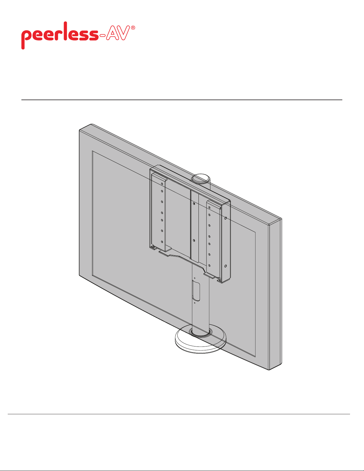
Installation and Assembly:
Desktop Swivel Mount with Cam Locks for VESA 200 x 200
and VESA 200 x 100 Displays
Model: HP437-C# (52-63)
Maximum Load Capacity: 80 lb (36.3 kg)
2300 White Oak Circle. • Aurora, IL 60502 • (800) 865-2112 • Fax: (800) 359-6500 • www.peerless-av.com
ISSUED: 12-13-2013 SHEET #: 125-9086-9
Page 2
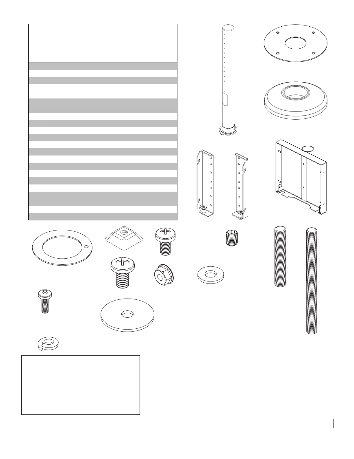
Parts List
Description Qty. Part#
A
support tube 1 090-1783-1
B base backer plate 1 090-1544
C swivel base 1 090-1821
D right bracket 1 See Chart
on Page 3
E left bracket 1 See Chart
on Page 3
F adapter bracket box 1 090-1913
G #8 washer 4 540-1001
H thrust washer 1 590-1287
I
slope nuts 3 530-0035
J 1/4-20 x 1/2" phillips screw 2 510-9108
K M6 x 12 mm phillips screw 4 520-1128
L M4 x 12 mm phillips screw 4 504-9013
M 10-32 x 1/2" set screw 2 520-1614
N 1/4-20 x 1.5" threaded rod 4 520-2250
O 1/4-20 x 3" threaded rod 4 520-2585
P flanged lock nut 4 530-2021
R
loc-tite 271 thread lock
adhesive (not shown)
1 570-0040
T fender washer 4 540-1008
U 1/4" split washer 2 540-9402
Before you begin, make sure all parts shown are included
with your product.
NOTE: Read instruction sheet before you start installation and assembly.
A
D E
B
C
F
H
I
J
L
U
Tools Needed for Assembly
• drill • 5 mm allen wrench
• 17/64" drill bit
• phillips screwdriver
• 3/32" allen wrench
• 5/16" box wrench
Visit the Peerless Web Site at www.peerless-av.com For customer care call 1-800 865-2112
• hole saw
T
K
P
2 of 9
G
M
N
ISSUED: 12-13-2013 SHEET #: 125-9086-9
O
Page 3

Chart
Description Qty. Part#
HP437-C52 D right vertical bracket 1 091-1111
E left vertical bracket 1 091-1112
HP437-C53 D right vertical bracket 1 091-1113
E left vertical bracket 1 091-1114
HP437-C54 D right vertical bracket 1 091-1115
E left vertical bracket 1 091-1116
HP437-C55 D right vertical bracket 1 091-1117
E left vertical bracket 1 091-1118
HP437-C56 D right vertical bracket 1 091-1119
E left vertical bracket 1 091-1120
HP437-C57 D right vertical bracket 1 091-1121
E left vertical bracket 1 091-1122
HP437-C58 D right vertical bracket 1 091-1123
E left vertical bracket 1 091-1124
HP437-C59 D right vertical bracket 1 091-1125
E left vertical bracket 1 091-1126
HP437-C60 D right vertical bracket 1 091-1127
E left vertical bracket 1 091-1128
HP437-C61 D right vertical bracket 1 091-1129
E left vertical bracket 1 091-1130
HP437-C62 D right vertical bracket 1 091-1131
E left vertical bracket 1 091-1132
HP437-C63 D right vertical bracket 1 091-1133
E left vertical bracket 1 091-1134
3 of 9
Visit the Peerless Web Site at www.peerless-av.com For customer care call 1-800 865-2112
ISSUED: 12-13-2013 SHEET #: 125-9086-9
Page 4

Use base backer plate (B) as a template to mark location of holes. Drill four holes using a 17/64'' drill bit in a
1
square formation. In the center of the square formation drill a 2" to 3" cable management hole.
SQUARE FORMATION
B
CABLE MANAGEMENT
CUT-OUT
FRONT OF DISPLAY
BOTTOM VIEW
g. 1.1
WARNING
• Wooden mounting surface requires a minimum of 3/4" thickness to hold display securely
If the desk thickness is 3/4" use 1/4-20 x 1.5"
2
threaded rods (N). If the desk thickness is between
3/4" to 2-1/4" use 1/4-20 x 3" threaded rods (O). Turn
base (C) upside down and insert four threaded rods
(N or O) into base (C), as shown below.
NOTE: Threaded rods must fasten a minimum of
three turns.
NOTE: If enhanced security is desired, use three
drops of loc-tite 271 thread lock adhesive (R) along
1/4" at the end of each threaded rod. Insert adhesive
end of threaded rods (N or O) into bottom of base
(C).
N or O
Turn base (C) upside down insert support tube (A),
3
and thrust washer (H) as shown below.
A
H
C
C
g. 2.1
4 of 9
Visit the Peerless Web Site at www.peerless-av.com For customer care call 1-800 865-2112
ISSUED: 12-13-2013 SHEET #: 125-9086-9
g. 3.1
Page 5
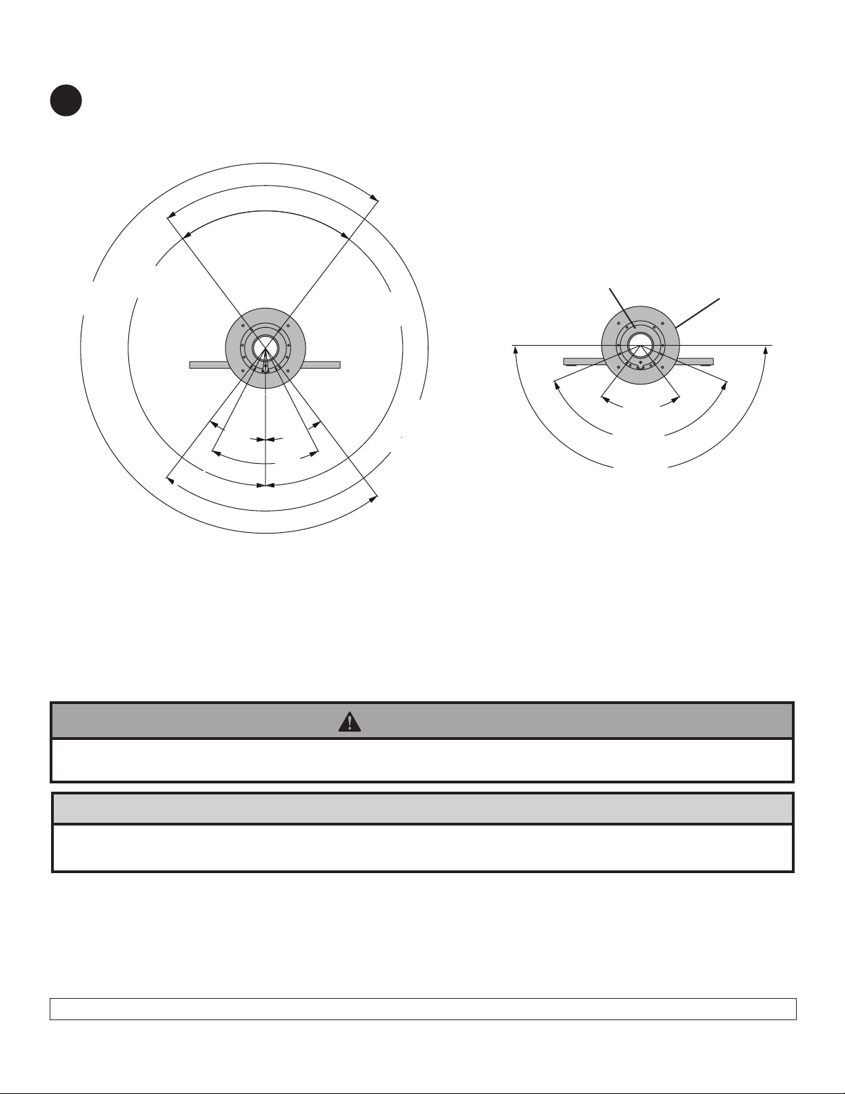
Swivel Restriction
Refer to g. 4.1 and 4.2, select the desired swivel degree. Using a 3/32" allen wrench, fasten two set screws (M)
4
where indicated below to the outside of desired angle in steel base (C).
NOTE: Set screws (M) must be bottomed out into base.
240°
210°
FRONT
g. 4.1
30°30°
40°
A
C
210°
LOCK AT 0°
60°
240°
120°
180°
FRONT
g. 4.2
Mounting to Support Surface
WARNING
• Make sure that the supporting surface will safely support the combined load of the equipment and all attached
hardware and components
CAUTION
• Installations to desktops that have a gap between two supporting boards are not acceptable mounting surfaces
for the HP line of desktop swivel mounts.
Mounting using Non-Security....................................................................Step 5 Page 5
Mounting using Security Slop Nuts (Optional) .......................................Step 7 Page 5
5 of 9
Visit the Peerless Web Site at www.peerless-av.com For customer care call 1-800 865-2112
ISSUED: 12-13-2013 SHEET #: 125-9086-9
Page 6

Mounting using Non-Security
Line up backer plate (B) with threaded rods
5 6
(N or O).
NOTE: Washer (H) must be centered.
Using four fender washers (T) and four lock nuts (P)
tighten in numbered pattern as shown in Figure 6.1.
At minimum 1/4 - 20 locknuts (P) should be ush with
bottom of threaded rods (N or ).
Line up base assembly (step 5), through supporting
surface with pattern of base (C) facing the front as
shown in Detail 1.
B
N or O
C
FRONT OF
SCREEN
3
1
2
g. 5.1
g. 6.1
4
Mounting using Security Slope Nuts (Optional)
For added security replace two of
7
the washers and locknuts with slope
nuts.
Hand tighten slope nuts (I) onto
two of the thread rods (M) till snug
against bottom of table as shown in
Detail 2.
Thread another slope nut (I) upside-
down, about two turns from rst
slope nut (I) as shown in Detail 3.
Insert a 5/8" open box wrench
between both slope nuts (I) and
tighten
as shown in detail 4.
BOTTOM OF DESK
I
N or O
Detail 2 Detail 3
Detail 4
BOTTOM OF DESK
FRONT OF
SCREEN
T
C
N or O
NOTE: Avoid jamming both slope nuts (I) together,
doing so may make it difcult to remove slope nut
used for tightening.
After slope nut is secure remove bottom slope nut.
Detail 1
I
LEAVE SPACE
IN BETWEEN
SLOPE NUTS
TIGHTENING
SLOPE NUT (I)
N or O
I
TIGHTENING
SLOPE NUT (I)
6 of 9
Visit the Peerless Web Site at www.peerless-av.com For customer care call 1-800 865-2112
5/8" OPEN BOX WRENCH
ISSUED: 12-13-2013 SHEET #: 125-9086-9
Page 7

Attach adapter bracket box (F) to support tube (A) with two 1/4-20 x 1/2" phillips screw (J) and 1/4" split
8
washer (U) as shown in g 7.1.
F
A
F
U
J
A
Select desired mounting pattern from list below.
9
NOTE: Make sure that jack inputs on the back of the display are not covered by the adapter bracket box. Move the
vertical adapter brackets up or down accordingly to ensure accessibility.
ADAPTER BRACKET BOX
X
Mounting Hole Patterns
200 x 100 mounting pattern. Use four M4 x 12 mm phillips screws
200 x 100 mounting pattern. Use four M4 x 12 mm phillips screws
DISPLAY JACK INPUTS
200 x 100 mounting pattern. Use four M4 x 12 mm phillips screws
200 x 100 mounting pattern. Use four M4 x 12 mm phillips screws
200 x 200 mounting pattern. Use four M6 x 12 mm phillips screws
X
7 of 9
Visit the Peerless Web Site at www.peerless-av.com For customer care call 1-800 865-2112
ISSUED: 12-13-2013 SHEET #: 125-9086-9
Page 8

Secure right and left vertical brackets (D and E) to display using four M4 x 12 mm phillips screws (K) and
10
#8 washers (G) or four M6 x 12 mm phillips screws (L).
DISPLAY
D
G
K or L
NOTE: To complete the installation, two keys for the cam locks must be obtained from the General Man-
11
ager or Purchaser/Receiver of the mounting product. The display and mount installation cannot be completed without these two keys. Be sure to return the keys to the General Manager or responsible party upon
completion of the installation. Only a limited number of keys is supplied per installation location.
Insert the keys into the bottom of the locks and rotate to the unlocked position as shown in Detail 4 and 5.
Note that the keys are NOT removable in the open position.
E
Detail 4
8 of 9
Visit the Peerless Web Site at www.peerless-av.com For customer care call 1-800 865-2112
Detail 5
ISSUED: 12-13-2013 SHEET #: 125-9086-9
Page 9

NOTE: Locks must be in the open or unlocked position to continue installation.
12
Hook vertical brackets (D and E) into adapter bracket box (A) engaging adapter pins as shown in g. 5.1 and detail 6.
Rotate keys to locked position and remove keys as shown in gure 5.2. Return the keys to the General Manager or
responsible party immediately after installation is complete.
NOTE: Run cables from the jack inputs and power location through the cable management hole in the support tube
and down through the desktop surface.
A
g. 12.1
A
D
Detail 6
MOUNTING SURFACE
NOT SHOWN FOR CLARITY
E
g. 12.2
ADAPTER PIN
ADAPTER PIN
9 of 9
Visit the Peerless Web Site at www.peerless-av.com For customer care call 1-800 865-2112
ISSUED: 12-13-2013 SHEET #: 125-9086-9
 Loading...