

Page 1
Installation and Assembly:
A
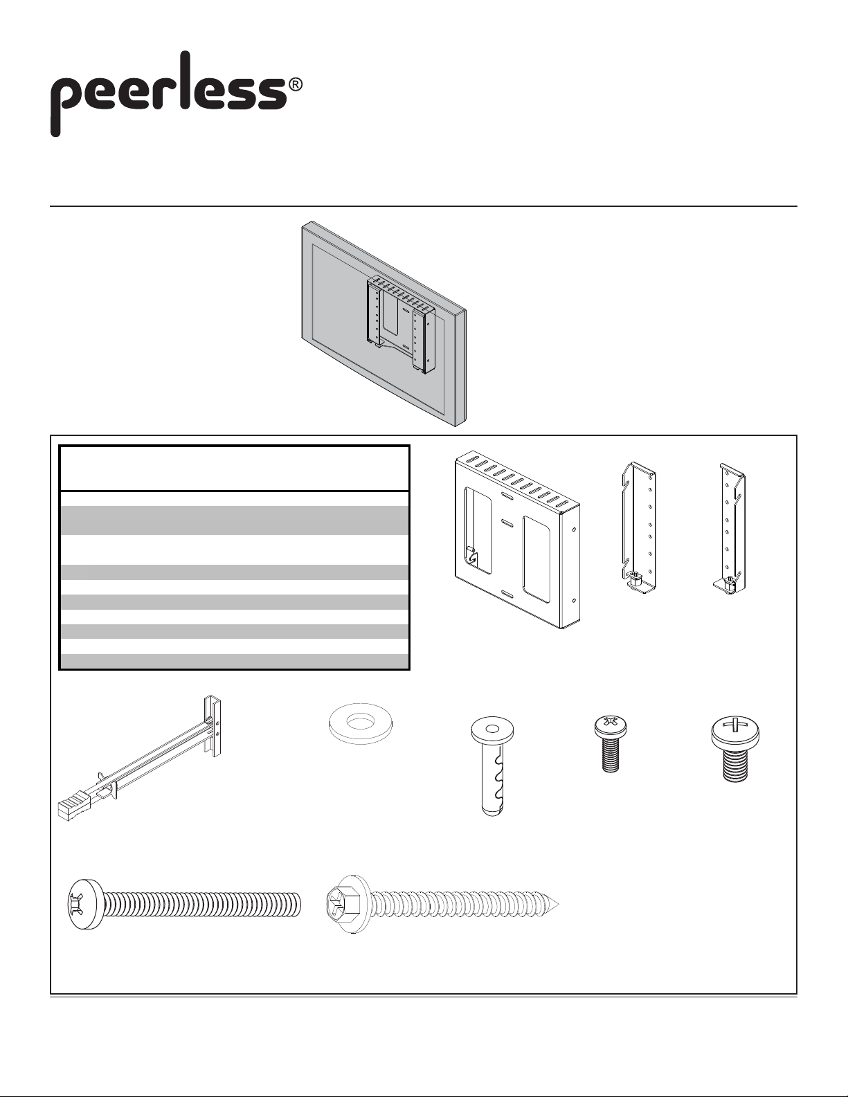
Flat Wall Mount for VESA 200 x 200 and VESA 200 x 100 Screens
Model: HF646-C%
Maximum Load Capacity: 80 lb (36.3 kg)
Parts List
Description Qty. Part #
wall bracket 1 090-1907
right vertical bracket 1 SEE CHART
B
ON PAGE 2
left vertical bracket 1 SEE CHART
C
ON PAGE 2
1/4-20 toggler 3 560-9708
D
#8 washer 4 540-1001
E
1/4-20 x 2.5 phillips screw 3 520-9521
F
#14 x 2.5 hex phillips wood screw 3 5S1-015-C03
G
alligator anchor 3 590-0097
H
M4 x 12 mm phillips screw 4 504-9013
I
M6 x 12 mm phillips screw 4 520-1128
J
DEHIJ
A
B
C
F
Before you start make sure all parts listed are included with your product.
3215 W. North Ave. • Melrose Park, IL 60160 • (800) 729-0307 or (708) 865-8870 • Fax: (708) 865-2941 • www.peerlessmounts.com
G
ISSUED: 10-22-09 SHEET #: 125-9085-2 11-18-09
Page 2
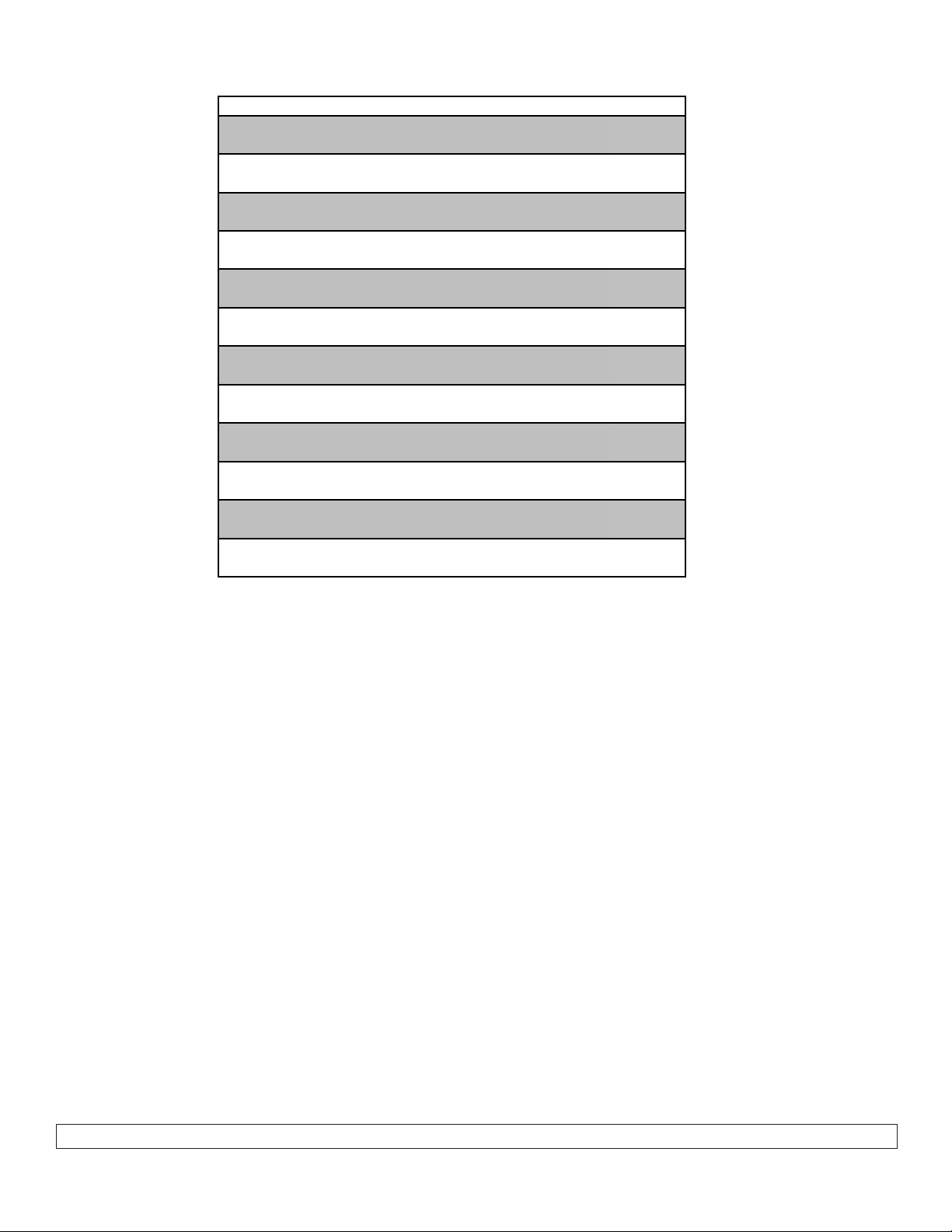
Description Qty. Part#
HF646-C52 D right vertical bracket 1 090-1914
E left vertical bracket 1 090-1915
HF646-C53 D right vertical bracket 1 090-1916
E left vertical bracket 1 090-1917
HF646-C54 D right vertical bracket 1 090-1918
E left vertical bracket 1 090-1919
HF646-C55 D right vertical bracket 1 090-1920
E left vertical bracket 1 090-1921
HF646-C56 D right vertical bracket 1 090-1922
E left vertical bracket 1 090-1923
HF646-C57 D right vertical bracket 1 090-1924
E left vertical bracket 1 090-1925
HF646-C58 D right vertical bracket 1 090-1926
E left vertical bracket 1 090-1927
HF646-C59 D right vertical bracket 1 090-1928
E left vertical bracket 1 090-1929
HF646-C60 D right vertical bracket 1 090-1930
E left vertical bracket 1 090-1931
HF646-C61 D right vertical bracket 1 090-1932
E left vertical bracket 1 090-1933
HF646-C62 D right vertical bracket 1 090-1934
E left vertical bracket 1 090-1935
HF646-C63 D right vertical bracket 1 090-1936
E left vertical bracket 1 090-1937
2 of 7
ISSUED: 10-22-09 SHEET #: 125-9085-2 11-18-09
Page 3
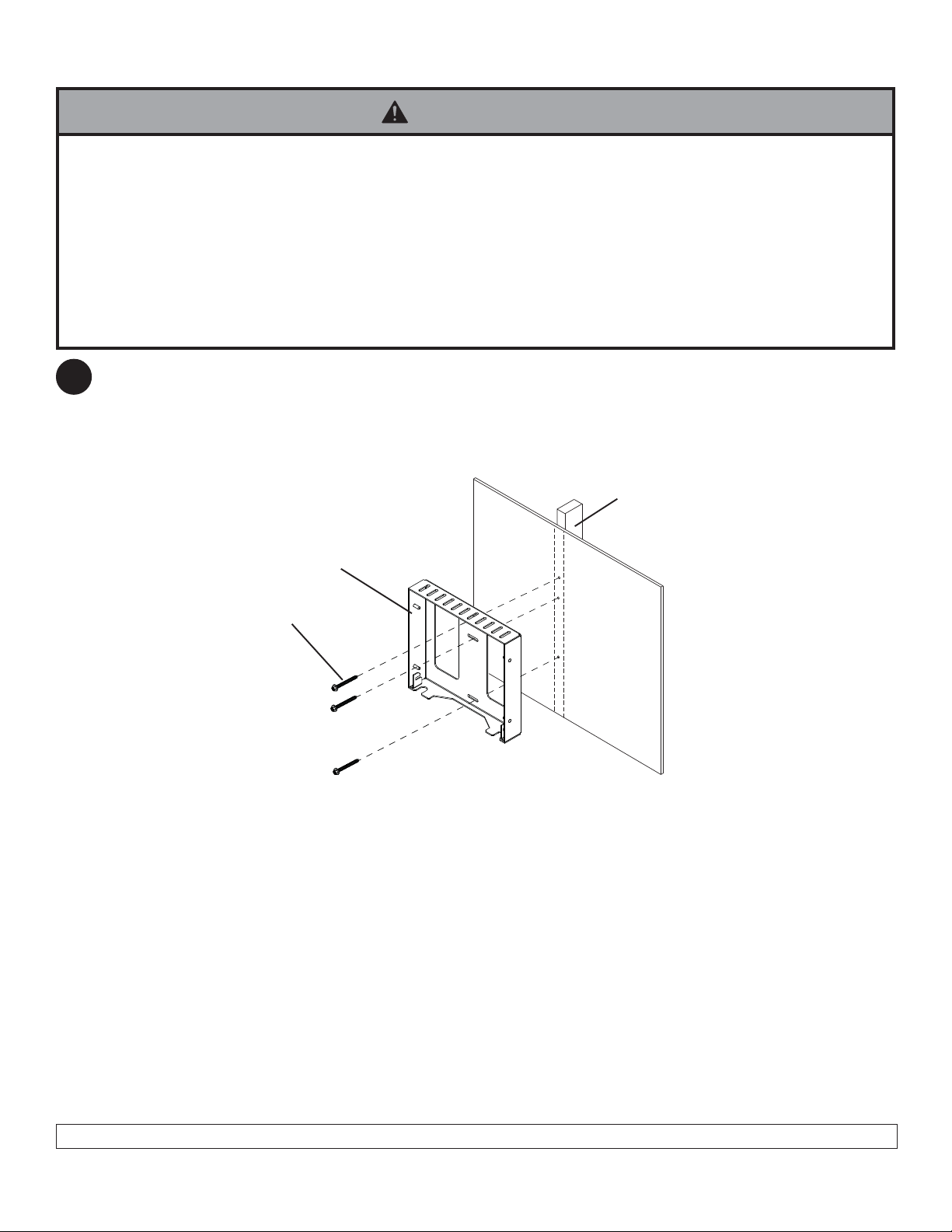
Installation to Single Wood Stud Wall
WARNING
• Installer must verify that the supporting surface will safely support the combined weight of all attached equipment and
hardware.
• Tighten wood screws so that wall plate is firmly attached, but do not overtighten. Overtightening can damage the
screws, greatly reducing their holding power.
• Never tighten in excess of 80 in. • lb (9 N.M.).
• Make sure that mounting screws are anchored into the center of the stud. The use of an "edge to edge" stud finder is
highly recommended.
• Hardware provided is for attachment of mount through standard thickness drywall or plaster into wood studs. Installers
are responsible to provide hardware for other types of mounting situations.
Use a stud finder to locate the edges of the stud. Use of an edge-to-edge stud finder is highly recommended. Based
1
on its edges, draw a vertical line down the stud’s center . Place wall bracket (A) on wall as a template, making sure
that the three mounting holes are over the stud centerline. Level plate, and mark the center of the three holes. Drill
three 5/32" (4 mm) dia. holes 2-1/2" (64 mm) deep. Make sure that the wall plate is level, secure it using three
#14 x 2.5" wood screws (G) as shown in figure 1.2.
Skip to step 2 on page 5.
STUD
G
A
3 of 7
ISSUED: 10-22-09 SHEET #: 125-9085-2 11-18-09
Page 4

Installation to Solid Concrete Surface
WARNING
• When installing Peerless wall mounts on cinder block, verify that you have a minimum of 1-3/8" of actual concrete
thickness in the hole to be used for the concrete anchors. Do not drill into mortar joints! Be sure to mount in a solid
part of the block, generally 1" minimum from the side of the block. Cinder block must meet ASTM C-90 specifications.
It is suggested that a standard electric drill on slow setting is used to drill the hole instead of a hammer drill to avoid
breaking out the back of the hole when entering a void or cavity .
• Concrete must be 2000 psi density minimum. Lighter density concrete may not hold concrete anchor .
• Make sure that the supporting surface will safely support the combined load of the equipment and all attached hardware and components.
Position wall bracket (A) at desired position on wall. Use wall
1
bracket (A), making sure that it is level, as a template to mark
holes. Drill three 1/4" (6 mm) dia. holes to a minimum depth of
2-1/2" (64 mm). Concrete must be 2000 psi density minimum.
Insert anchors (H) in holes flush with wall as shown in figure
1.1. Place wall bracket (A) over anchors and secure with three
#14 x 2-1/2" wood screws (G) as shown in figure 1.2. Make
sure wall bracket (A) is level and tighten all fasteners.
Skip to step 2 on page 5.
1
Drill holes and insert anchors (H).
2
A
concrete
wall
H
WARNING
• Tighten wood screws firmly , but do not overtighten.
Overtightening can damage the screws, greatly
reducing their holding power.
• Never tighten in excess of 80 in • lb (9 N.M.).
• Concrete anchors are not intended for attachment to
concrete wall covered with a layer of plaster, drywall,
or other finishing material as shown below. If mounting
to concrete wall covered with plaster/drywall is unavoidable, plaster/drywall (up to 5/8" thick) must be
counterbored as shown below. Be sure concrete
anchors do not pull away from concrete when tightening screws. If plaster/drywall is thicker than
5/8", custom fasteners must be supplied by installer.
INCORRECT
concrete
plaster/
dry wall
CUT AW A Y VIEW
CORRECT
concrete
plaster/
dry wall
G
Place plate (A) over anchors (H) and secure with
screws (G).
3
Tighten all fasteners.
SOLID CONCRETE
CINDER BLOCK
fig 1.1
H
4 of 7
G
H
A
ISSUED: 10-22-09 SHEET #: 125-9085-2 11-18-09
fig 1.2
Page 5

FOR MET AL STUD W ALLS ONL Y : Drill three 1/2" (13 mm) dia.
holes through drywall and studs at locations corresponding to
wall bracket (A). Insert togglers (D) as shown below .
Secure using three 1/4-20 x 2.5 phillips screws (F).
WARNING
D
A
• Product must be mounted through drywall that has a
minimum thickness of 1/2" and into metal studs, 26
gauge or heavier.
• Make sure that togglers are anchored into the center
of the studs as shown in figure 1.3. The use of an
"edge to edge" stud finder is highly recommended.
Pivot end of toggler (D).
D
Push into hole.
Rotate toggler (D)
clockwise to wedge it
against inside walls
of metal stud.
F
fig. 1.3
Slide plastic cap
forward while pulling
back firmly on ring.
Break off excess.
Align wall bracket (A)
with hole in wall and
fasten using
1/4-20 x 2.5" screw (F).
F
A
5 of 7
ISSUED: 10-22-09 SHEET #: 125-9085-2 11-18-09
Page 6

Select desired mounting pattern from list below.
2
NOTE: Make sure Screen Jack Pack on back of screen is accesible.
WALL BRACKET
X
Mounting Patterns
200 x 100 mounting pattern. Use four M4 x 12 mm phillips screws
200 x 100 mounting pattern. Use four M4 x 12 mm phillips screws
200 x 100 mounting pattern. Use four M4 x 12 mm phillips screws
200 x 100 mounting pattern. Use four M4 x 12 mm phillips screws
200 x 200 mounting pattern. Use four M6 x 12 mm phillips screws
X
Secure right and left vertical brackets (B and C) to screen using four M4 x 12 mm phillips screws (I) and
3
#8 washers (E) or four M6 x 12 mm phillips screws (J).
SCREEN
SCREEN JACK PACK
B
E
I or J
C
6 of 7
ISSUED: 10-22-09 SHEET #: 125-9085-2 11-18-09
Page 7

NOTE: To continue installation, two keys and lock tool (Optional tool accessory available) need to
4
be retrieved from General Manager of property. Screen cannot be installed without them.
Insert keys into bottom of locks and rotate to the unlocked position as shown in details 1 and 2. Keys are not
removable in open position.
OPTIONAL ACCESSOR Y
TOOL A V AILABLE
(Contact Customer Care)
Detail 1
NOTE: Locks must be in open position to continue installation.
5
Hook vertical brackets (B and C) onto wall bracket (A) engaging adapter pins as shown in fig. 5.1 and detail 3.
Rotate keys to locked position and remove keys as shown in figure 5.2.
Detail 2
fig. 5.1
A
B
C
ADAPTER PIN
ADAPTER PIN
MOUNTING SURFACE
NOT SHOWN FOR CLARITY
fig. 5.2
Detail 3
7 of 7
All other brand and product names are trademarks or registered trademarks of their respective owners.
ISSUED: 10-22-09 SHEET #: 125-9085-2 11-18-09
© 2009, Peerless Industries, Inc. All rights reserved.
 Loading...