

Page 1
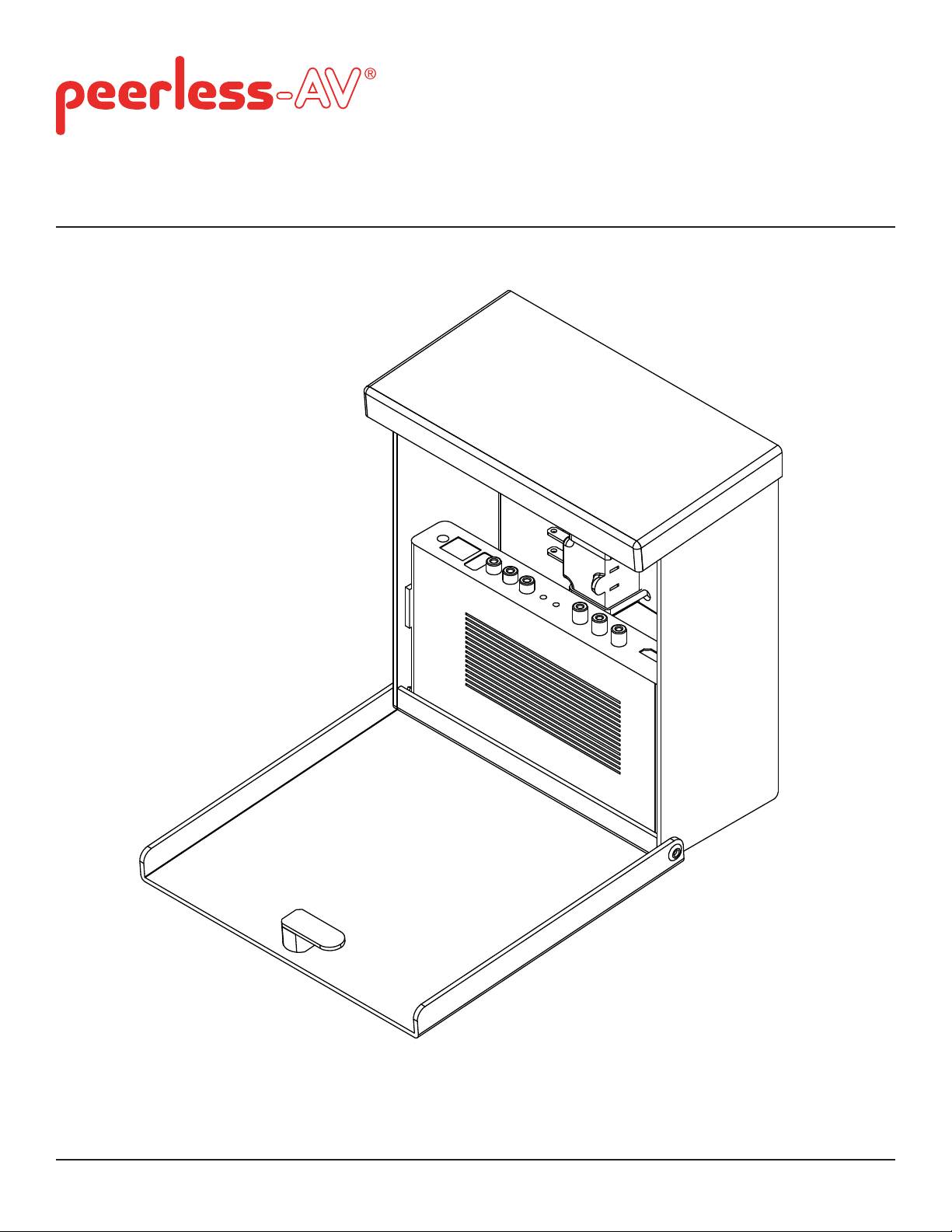
Installation and Assembly:
Outdoor Wireless Kit
Models: HDS-OWK-%
2300 White Oak Circle • Aurora, Il 60502 • (800) 865-2112 • Fax: (800) 359-6500 • www.peerless-av.com
2016-09-07 SHEET #: 180-9091-1
Page 2

Note: Read entire instruction sheet before you start installation and assembly.
WARNING
• Do not begin to install your Peerless product until you have read and understood the instructions and warnings
contained in this Installation Sheet. If you have any questions regarding any of the instructions or warnings, for US
customers please call Peerless customer care at 1-800-865-2112, for all international customers, please contact
your local distributor.
• This product should only be installed by someone of good mechanical aptitude, has experience with basic building
construction, and fully understands these instructions.
• Due to outdoor environmental conditions such as heavy snow, hail, rain, etc. the environmental mount and
hardware must be inspected at least once a year. This product should not be exposed to high winds. A qualifi ed
installer or inspector must check for signs of rust, loose fasteners, bent metal, etc. If evidence of excessive wear,
deterioration or any unsafe condition is observed, this product must be taken out of service immediately. Direct all
inquiries to customer care if you have any questions.
• Make sure that the supporting surface will safely support the combined load of the equipment and all attached
hardware and components.
• Never exceed the Maximum Load Capacity. See page one.
• If mounting to wood wall studs, make sure that mounting screws are anchored into the center of the studs. Use of
an "edge to edge" stud fi nder is highly recommended.
• Always use an assistant or mechanical lifting equipment to safely lift and position equipment.
• Tighten screws fi rmly, but do not overtighten. Overtightening can damage the items, greatly reducing their holding
power.
• This product was designed to be installed on the following wall construction only;
WALL CONSTRUCTION HARDWARE REQUIRED
• Wood Stud Included
• Wood Beam Included
• Solid Concrete Included
• Cinder Block Included
• Metal Stud Contact Qualifi ed Professional
• Brick Contact Qualifi ed Professional
• Other or unsure? Contact Qualifi ed Professional
Tools Needed for Assembly
• stud fi nder ("edge to edge" stud fi nder is recommended)
• phillips screwdriver
• drill
• 5/16" (8 mm) bit for concrete and cinder block wall
• 5/32" (4 mm) bit for wood stud wall
• level
• 7/16" open end wrench
• 5mm allen wrench
• 6mm allen wrench
Table of Contents
Parts List.............................................................................................................................................................................3, 4
Enclosure Wall installation ......................................................................................................................................................5
Enclosure Installation to ESA763PU Articulating Wall Mount .................................................................................................7
Enclosure Installation to EPT650 Tilt Wall Mount .................................................................................................................16
Wireless Receiver Setup ......................................................................................................................................................18
2 of 22
2016-09-07 SHEET #: 180-9091-1
Page 3
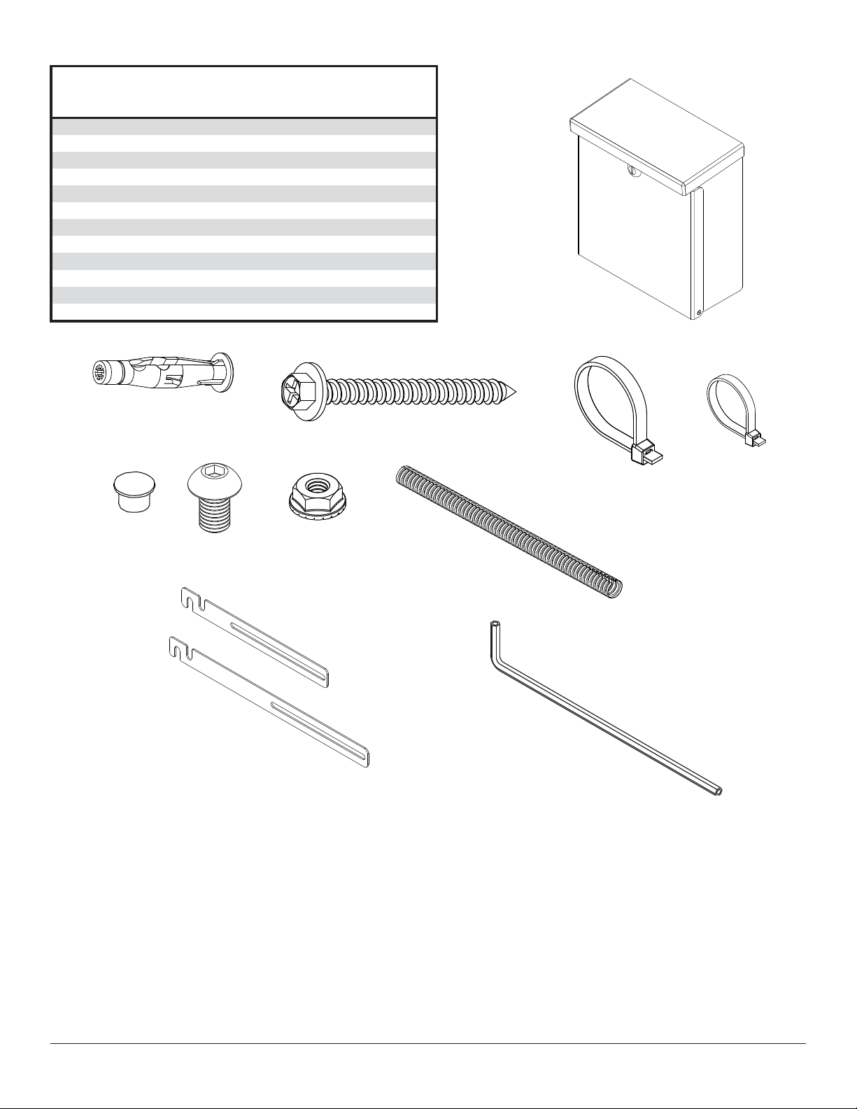
Before you begin, make sure all parts shown are included with your product.
Parts List
wireless receiver assembly, outdoor 1 180-1427
A
B
C
D cable tie .187 x 7.5 lg.
E cable tie .04 x 5.75 lg.
F push-in round plastic plug, 3/8"
1/4-20 x 1/2 socket head screw 6 500-2093
G
H
I
enclosure mounting bracket, small 2 120-T1195
J
enclosure mounting bracket, large 2 120-T1196
K
L
Parts may appear slightly different than illustrated.
B
F
02-4/1 tun kcol
C
G
H
HDS-OWK-%
2 590-1168
4 560-9711
4 590-9465
# traP.ytQnoitpircseD
0230-0952rohcna etercnoc
3305-0252wercs doow "5.2 x 41#
3105-0356
8649-0951htaehs tnemeganam elbac
6469-0651hcnerw nella mm 4
D
E
I
A
K
J
L
3 of 22
2016-09-07 SHEET #: 180-9091-1
Page 4
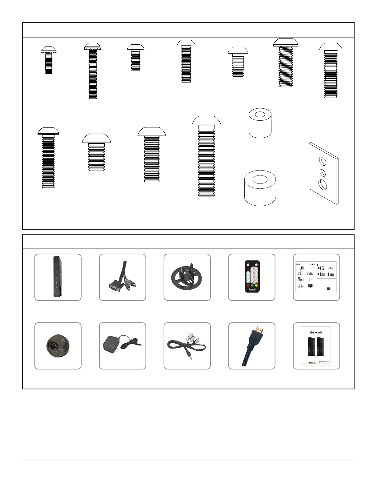
Adapter Bracket Fasteners
S
M4 x 12 mm (6)
(510-D1079)
M6 x 30 mm (4)
(520-D1067)
M4 x 25 mm (4)
(510-D1082)
M8 x 12 mm (6)
(520-D1068)
Additional Wireless Components
M5 x 12 mm (4)
(520-D1064)
M8 x 25 mm (4)
(520-D1101)
M5 x 25 mm (4)
(520-D1122)
M8 x 40 mm (4)
(520-D1152)
M6 x 12 mm (4)
(520-D1050)
I.D. .22" (4)
(540-1057)
I.D. .34" (4)
(540-1059)
M6 x 20 mm (4)
(520-D1554)
M6 x 25 mm (4)
(520-D1211)
multi-washer (6)
(580-D1036)
wireless transmitter (1) vga to rca adapter (1) remote (1)
plastic stand (1)
ir fl asher (1)
hdmi cable (2)
®
READY
Quick Start Guide
Step 7 While turning on the display device the HD Flow Pro Wireless Multimedia units will be going through the startup process. This process may
PRO WIRELESS MULTIMEDIA KIT
What’s in the Box
Installation and Setup
Step 1 Connect the Transmitter to the source devices
(Blu-ray™ Disc player, set top box, gaming console, etc.).
Tip Repeat Steps
teps
ect
3-11 to connect
ne
more than one
t
Receiver unit
(HDS200-2,
HDS200-3,
HDS200-4).
Step 3 Connect the display device (TV, monitor, projector, etc.)
tthdil d i(TV it jt t)
to the Receiver.
Step 5 Power-up the HD Flow Pro Devices.
1. Plug in the power adapter for the Transmitter and the Receiver to nearby
available power outlets.
2. Plug in the power adapter end to the Transmitter and then to the Receiver.
3. The units will automatically turn-on. The average power-on/sync time
is approximately two minutes.
© 2012 Peerless Industries, Inc. Peerless-AV™ is a trademark of Peerless Industries, Inc. All rights reserved.
HD Flow™ is a trademark of I Do It, LTD. Other parties’ marks are the property of their respective owners. hdflow.com
take up to two minutes to complete. The Power/Link indicator lights on the Transmitter and the Receiver will be flashing at first. Flashing indicates
Model No. HDS200 (-2, -3, -4)
2
Minutes
that the units are establishing a secure connection. Wait until the connection is successfully established, indicated by the Power/Link indicator
light becoming solid.
1 x Transmitter
1 x IR Extender
1 x Receiver
1 x Component Adaptor
2 x Stand
2 x Power Adapter
1 x Remote Control
1 x Quick Start Guide
1 x IR Flasher
1 x Users Manual
Power/Source
Selection Button
Step 8 Select the output that connects the Receiver to the display using
the Power/Source Selection Button or the provided remote control.
The output indicator light will become solid and the HD Flow logo will
appear on the display device.
Tip The IR window
may be easier to
locate with a direct
light shining on
sections of the
front panel of the
component device.
A small flashlight
works well.
Power/Source
Step 2 Connect the provided IR Flasher to the IR-OUT port on the Transmitter.
Selection Button
Find the location of the IR window on your source device and adhere the
IR Flasher eye directly over the IR window on your source device.
NOTE: One IR Flasher eye is to be used for one component device.
Step 10 Select the desired source or device input on the Transmitter
using the Power/Source Selection Button on the remote control.
Troubleshooting Tips
Transmitter and/or Receiver Indicator Lights are all Blinking:
• The HD Flow Pro units are establishing a connection. It can take
up to two minutes for the HD Flow Pro units to establish a complete
connection. If after two minutes have passed and the units have not
established a connection, unplug the power cable, wait 30 seconds
and reconnect the power supply to the units.
Transmitter or Receiver Power Indicator Light is OFF:
Step 4 Install the IR Extender by plugging in the provided IR Extender in to
• Check and verify the power supply connection.
the IR-IN port on the Receiver and adhering the other end of the IR Extender
to a vertical surface near the output device. Ensure that the IR Extender is in
Transmitter Input Indicator Light Blinks:
a line of sight to the remote control that controls your source devices.
• Make sure that your source device is turned ON and the cable
NOTE: For Multicast models, receivers two, three and four do not come with an IR Extender. Additional IR Extenders
(HDS-IRE) can be purchased separately; visit peerless-av.com for more information.
is properly connected.
• Verify that the Transmitter is set to the appropriate input port.
• Check the resolution from your source device. This may need to
be changed to a resolution supported by the HD Flow Pro Wireless
Multimedia Kit. Reference the Resolution Chart in the HD Flow Pro
Manual for compatibility. Reference your source devices’ manual
for instruction on changing the output resolution.
Receiver Power Indicator Light Blinks:
• Verify that the HD Flow Pro Transmitter and Receiver are within
the recommended range of 131 feet. Physical obstructions such as
walls, floors and ceilings between the Transmitter and Receiver may
decrease the strength of the connection signal and reduce the overall
transmission range.
Step 6 Turn on your display device (TV, monitor, projector, etc.).
If a connection has been established and the HD Flow logo can be seen
on the display device, but content is not playing:
• Make sure that the input/output cables are properly connected.
• Verify that the Transmitter is set to the appropriate input port.
install guide (1)
User Manual and Installation Guide
Pro Wireless Multimedia Kit
Models:
HDS200
HDS200-2
HDS200-3
®
READY
HDS200-4
instruction sheet (1)12v power adapter (1)3v battery (1)
ISSUED: 06-12-12 SHEET #: 180-9023-1
Step 9 Turn on the desired source device that is connected to
the Transmitter.
Step 11 Play the source device content and enjoy up to Full HD 1080p
wireless entertainment experience.
• Check the media source resolution. The display device must be able
to support the resolution of the media source that is being streamed.
Utilizing the INFO button will allow you to see the resolution data that
the display device supports. If the display device supports the highest
resolution of 720p but the source device is outputting 1080p content,
the content needs to be down-scaled to the maximum resolution of the
display device, in this case 720p.
Receiver Output Indicator Light Blinks:
• Make sure that your display device, source device and the HD Flow Pro units
are all turned ON and the Receiver is properly connected to the output device.
• Verify that the Receiver is set to the appropriate output port.
• Check the resolution setting of your source device. This may need to be
changed to a resolution supported by the HD Flow Pro unit. Reference
the Resolution Chart in the HD Flow Pro Manual for compatibility.
Reference your source devices’ manual for instruction on changing
the output resolution.
If the above troubleshooting tips do not resolve the issues for a unicast setup,
please reference the Factory Reset Section of the HD Flow Pro Manual. For a
multicast system configuration, please contact Peerless-AV Customer Care at
800-856-2112 for further instruction.
Warning Do not place the HD Flow
Pro units near other devices that
emit excessive amounts of heat.
Increased temperatures may
cause the HD Flow Pro Transmitter
or Receiver unit to malfunction
or stop working.
Quick Start Guide for HD Flow Pro Wireless Multimedia Kit - LIT-0906
4 of 22
2016-09-07 SHEET #: 180-9091-1
Page 5
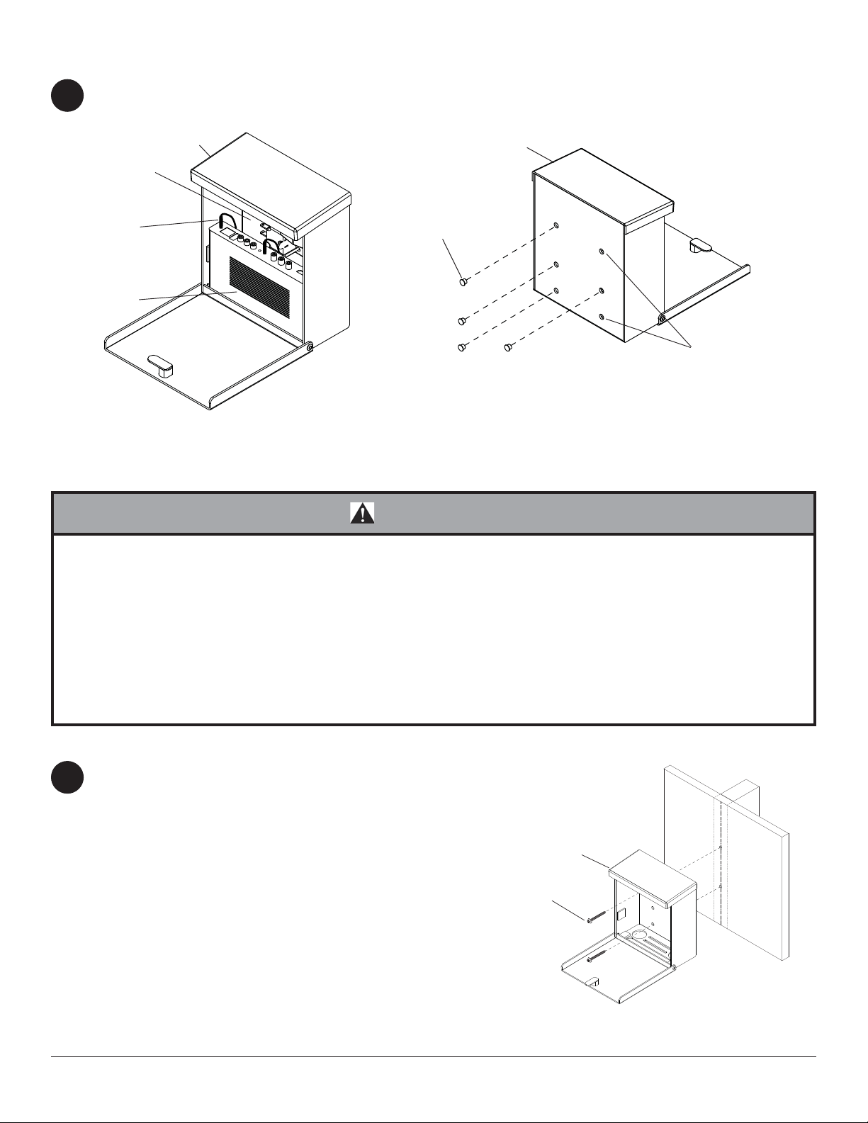
Enclosure Wall Installation
Open the wireless receiver enclosure (A) and unplug the wireless receiver power cord from the wireless receiver.
1
Remove the wireless receiver and sub panel assembly as shown in fi g. 1.1. Choose two holes for securing the
wireless receiver enclosure (A). Press in plastic plug (F) into the four remaining holes shown in fi gure 1.2.
SUB P ANEL
ASSEMBLY
WIRELESS
RECEIVER
POWER CORD
WIRELESS
RECEIVER
A
F
fi g. 1.1
A
MOUNTING
HOLES
fi g. 1.2
WARNING
• Installer must verify that the supporting surface will safely support the combined load of the equipment and all
attached hardware and components.
• Tighten wood screws so that the enclosure is fi rmly attached, but do not overtighten. Overtightening can damage
the screws, greatly reducing their holding power.
• Never tighten in excess of 80 in. • lb (9 N.M.).
• Make sure that mounting screws are anchored into the center of the stud. The use of an "edge to edge" stud fi nder
is highly recommended.
• Hardware provided is for attachment of mount through standard thickness drywall or plaster into wood studs. Installers are responsible to provide hardware for other types of mounting situations.
Installation to Single Wood Stud Wall
Use a stud fi nder to locate the edges of the stud. Use of an
2
edge-to-edge stud fi nder is highly recommended. Based
on its edges, draw a vertical line down the stud’s center.
Place enclosure on wall as a template, making sure that two
vertical mounting holes are over the stud centerline. Level the
enclosure, and mark the center of the two holes. Drill two 5/32"
(4mm) dia. holes 2-1/2" (64mm) deep. Make sure that the
enclosure is level, secure it using two #14 x 2-1/2" wood screws
(C) as shown.
Skip to step 7.
5 of 22
A
C
2016-09-07 SHEET #: 180-9091-1
Page 6

Enclosure Wall Installation to Solid Concrete or Cinder Block
WARNING
• Verify that you have a minimum of 1-3/8" (35mm) of actual concrete thickness in the hole to be used for the concrete anchors. Do not drill into mortar joints! Be sure to mount in a solid part of the block, generally 1" (25mm) minimum from the side of the block. Cinder block must meet ASTM C-90 specifi cations. It is suggested that a standard
electric drill on slow setting is used to drill the hole instead of a hammer drill to avoid breaking out the back of the
hole when entering a void or cavity.
• Concrete must be 2000 psi density minimum. Lighter density concrete may not hold concrete anchor.
• Make sure that the wall will safely support four times the combined load of the equipment and all attached hardware
and components.
Make sure that the enclosure is level, use it as a
2
template to mark two mounting holes. Drill two 5/16"
(8mm) dia. holes to a minimum depth of 2-1/2"
(64mm). Insert anchors (B) in holes fl ush with wall
as shown (right). Place the enclosure over anchors
and secure with two #14 x 2-1/2" screws (C). Level,
then tighten all fasteners.
WARNING
• Tighten screws so that wall plate is fi rmly attached,
but do not overtighten. Overtightening can damage
screws, greatly reducing their holding power.
• Never tighten in excess of 80 in. • lb (9 N.M.).
• Always attach concrete expansion anchors directly
to load-bearing concrete.
• Never attach concrete expansion anchors to
concrete covered with plaster, drywall, or other
fi nishing material. If mounting to concrete surfaces
covered with a fi nishing surface is unavoidable,
the fi nishing surface must be counter bored as
shown below. Be sure concrete anchors do not
pull away from concrete when tightening screws. If
plaster/drywall is thicker than 5/8" (16mm), custom
fasteners must be supplied by installer.
1
concrete
surface
B
Drill holes and insert anchors (B).
2
Place enclosure (A) over anchors (B) and secure with screws (C).
3
Tighten all fasteners.
SOLID CONCRETE
A
C
B
wall
plate
CUTAWAY VIEW
Skip to step 11.
plaster/
dry wall
INCORRECT CORRECT
concrete
wall
plate
plaster/
dry wall
concrete
6 of 22
C
A
B
CINDER BLOCK
2016-09-07 SHEET #: 180-9091-1
Page 7
Enclosure Installation to ESA763PU Articulating Wall Mount
NOTE: If display has a VESA 400 horizontal
mounting pattern, skip to step 4 on page 8.
NOTE: For VESA 200x200 or VESA 200x100
mount hole patterns, skip to step 6 on page 11.
Remove four 1/4-20 x .6" screws using 5 mm allen
3
wrench and loosen two 1/4-20 x 1.25" screws 1/2
turn to allow for display bracket adjustment.
1/4-20 x .6" SCREWS
1/4-20 x 1.25" SCREWS
3-1
To prevent scratching the display, set a cloth on a fl at, level surface that will support the weight of the display.
Place display face side down and refer to display manufacturers instructions for removing obstructions from the
back of the display. Adjust display brackets to align with display mounting holes.
Measure horizontal mounting hole pattern and choose fi xed stop-position from chart below.
horizontal mounting hole pattern fixed stop-position
10-3/4" - 16-1/16" (273 - 408 mm) #1
15-1/16" - 21-9/16" (383 - 548 mm) #2
20-7/16" - 27-9/16" (519 - 700 mm) #3
FIXED STOP-POSTION #3
FIXED STOP-POSTION #2
FIXED STOP-POSTION #1
7 of 22
2016-09-07 SHEET #: 180-9091-1
Page 8

Open the wireless receiver enclosure (A) and unplug the wireless receiver power cord from the wireless receiver.
4
Remove the wireless receiver and sub panel assembly as shown in fi g. 4.1. Loosely attach the small enclosure
mounting brackets (J) to the wireless receiver enclosure (A) with two 1/4-20 x 1/2 socket head screws (G) and
two 1/4-20 nuts (H) as shown in fi g. 4.2. NOTE: The enclosure mounting bracket can be installed with the inside
notch facing downward if additional side to side adjustment is needed. Position and tighten the four 1/4-20 x 1/2
socket head screws (G) using 4mm allen wrench (L). Press in two plastic plugs (F) into holes shown in fi gure 4.2.
A
SUB P ANEL
ASSEMBLY
WIRELESS
RECEIVER
POWER CORD
WIRELESS
RECEIVER
A
G
INSIDE NOTCH
H
J
fi g. 4.1
Attach the mounting brackets (J), open end of notch facing downward, to the left display bracket with two
5
1/4-20 x 1/2 socket head screws (G) and two 1/4-20 nuts (H) as shown in fi g. 5.1.
Adjust the position of the enclosure (A) to your desired location as shown in fi g. 5.2 Once in position, tighten the
four 1/4-20 x 1/2 socket head screws (G) using 4mm allen wrench (L).
F
fi g. 4.2
DISPLAY
BRACKET
H
A
fi g. 5.1
J
G
8 of 22
A
H
fi g. 5.2
2016-09-07 SHEET #: 180-9091-1
Page 9

Installing Adapter Brackets to Display
WARNING
• Tighten screws so display brackets are fi rmly attached to display. Do not tighten with excessive force.
Overtightening can cause stress damage to screws, greatly reducing their holding power and possibly causing
screw heads to become detached. Tighten to 40 in. • lb (4.5 N.M.) maximum torque.
• If screws don't get three complete turns in the display inserts or if screws bottom out and bracket is still not tightly
secured, damage may occur to display or product may fail.
5-1
Select the screws from the baffl ed fastener pack that best fi t your display and secure to display following step 5-2
on page 10.
NOTE: Top and bottom mounting holes must be used for attaching display brackets. Middle holes should also be
used where the fasteners and displays allow.
Verify that all holes are properly aligned, then tighten screws using a phillips screwdriver.
CENTER DISPLAY BRACKETS VERTICALLY AND
HORIZONTALLY ON BACK OF DISPLAY
DISPLAY
X
DISPLAY BRACKETS
Y
NOTE: "X" dimensions should be equal.
"Y" dimensions should be equal.
9 of 22
Y
X
2016-09-07 SHEET #: 180-9091-1
Page 10

5-2
NOTE: enclosure removed for clarity.
Begin with the longest length screw, hand thread
screw through multi-washer, display brackets and
spacer in that order into display as shown below.
Screw must make at least three full turns into the
mounting hole and fi t snug into place. Do not over
tighten. If screw cannot make three full turns into
the display, select a shorter length screw from
the baffl ed fastener pack. Repeat for remaining
mounting holes, level display brackets and tighten
screws.
DISPLAY
SPACER
MULTI-WASHER
SCREW
DISPLAY BRACKET
5-3
Center display brackets horizontally and vertically
on back of display. Tighten two 1/4-20 x 1.25"
screws. Reinstall four 1/4-20 x .6" screws using
a 5 mm allen wrench into appropriate fi xed-stop
position from chart on page 7.
1/4-20 x 1.25" SCREWS
1/4-20 x .6" SCREWS
10 of 22
2016-09-07 SHEET #: 180-9091-1
Page 11

Enclosure Installation to ESA763PU Articulating Wall Mount
VESA 200 x 200 or VESA 200 x 100 Mounting Pattern
Remove four 1/4-20 x .6" screws using a 5mm allen wrench
6
and loosen two 1/4-20 x 1.25" screws 1/2 turn to allow for
display bracket adjustment.
1/4-20 x .6" SCREWS
1/4-20 x 1.25" SCREWS
6-1
Remove four 1/4-20 self tapping screws to detach display brackets from outer mount holes of the universal
adapter bracket using a 5mm allen wrench as shown in fi gure 6.1. Reinstall four 1/4-20 self tapping screws to
secure display brackets to inner set of mounting holes on the universal adapter bracket as shown in fi gure 6.2.
1/4-20 SELF
T APPING SCREWS
To prevent scratching the display, set a cloth on a
fl at, level surface that will support the weight of the
display. Place display face side down and place the
universal adapter bracket onto display.
B
fi g. 6.1
OUTER
MOUNTING
HOLES
DISPLAY
BRACKETS
INNER
MOUNTING
HOLES
DISPLAY
BRACKETS
B
1/4-20 SELF
T APPING SCREWS
fi g. 6.2
11 of 22
2016-09-07 SHEET #: 180-9091-1
Page 12

6-2
Open the wireless receiver enclosure (A) and unplug the wireless receiver power cord from the wireless receiver.
Remove the wireless receiver and sub panel assembly as shown in fi g. 6.3. Loosely attach the large enclosure
mounting brackets (K) to the wireless receiver enclosure (A) with two 1/4-20 x 1/2 socket head screws (G) and
two 1/4-20 nuts (H) as shown in fi g. 6.4. NOTE: The enclosure mounting bracket can be installed with the inside
notch facing downward if additional side to side adjustment is needed. Position and tighten the four 1/4-20 x 1/2
socket head screws (G) using 4mm allen wrench (L). Press in two plastic plugs (F) into holes shown in fi gure 6.4.
SUB P ANEL
ASSEMBLY
WIRELESS
RECEIVER
POWER CORD
WIRELESS
RECEIVER
6-3
Slide universal adapter bracket to the side to expopse the display bracket mounting slots. Attach the mounting
brackets (K), open end of notch facing downward, to the left display bracket with two 1/4-20 x 1/2 socket head
screws (G) and two 1/4-20 nuts (H) as shown in fi g. 6.5.
A
G
A
K
H
F
fi g. 6.4
fi g. 6.3
G
DISPLAY
BRACKET
H
fi g. 6.5
12 of 22
2016-09-07 SHEET #: 180-9091-1
Page 13

6-4
Align one display bracket with one set of display mounting holes. Place spacers between display bracket and
display. Begin with the longest length screw, hand thread screw through the multi-washer, display brackets, and
spacer into display as shown. Screw must make at least three full turns into the mounting hole and fi t snug into
place. Do not over tighten. If screw cannot make three full turns into the display, select a shorter length screw
from the baffl ed fastener pack. Center display brackets vertically and tighten screws.
SCREW
6-5
MULTIWASHER
SPACER
DISPLAY
BRACKET
Slide universal adapter bracket to the opposite side to expopse the display bracket mounting slots. Place spacers
between display bracket and display. Begin with the longest length screw, hand thread screw through the multiwasher, display brackets, and spacer into display as shown. Screw must make at least three full turns into the
mounting hole and fi t snug into place. Do not over tighten. If screw cannot make three full turns into the display,
select a shorter length screw from the baffl ed fastener pack. Center display brackets vertically and tighten
screws.
SCREW
SPACER
DISPLAY
BRACKET
MULTIWASHER
13 of 22
2016-09-07 SHEET #: 180-9091-1
Page 14

6-6
Center the universal adapter bracket horizontally on back of display as shown in fi gure 6.6.
Tighten two 1/4-20 x 1.25" screws. Reinstall four 1/4-20 x .6" screws using a 5 mm allen wrench into fi xed-stop
position 1 as shown in fi gure 6.7.
1/4-20 x 1.25" SCREWS
FIXED STOP POSITION #1 WITH
fi g. 6.6
1/4-20 x .6" SCREWS
fi g. 6.7
6-7
Adjust the position of the enclosure (A) to your desired location as shown in fi g. 6.8 Once in position, tighten the
four 1/4-20 x 1/2 socket head screws (G) shown in fi g. 6.8 using 4mm allen wrench (L) and a 7/16" open end
wrench.
N
G
fi g. 6.8
14 of 22
2016-09-07 SHEET #: 180-9091-1
Page 15

WARNING
• Do not lift more weight than you can handle. Use additional man power or mechanical lifting equipment to safely
handle placement of the display.
• Do not tighten screws with excessive force. Overtightening can cause damage to mount. Tighten M10 x 15 mm
screws (E) to 40 in. • lb. (4.52 N.M.) maximum torque.
Mounting Flat Panel Display
Hook M10 x 15 mm screws into keyslots of wall arm adapter plate as shown fi gure 7.1.
7
1/4"
DISPLAY NOT
SHOWN FOR
CLARITY
M10 X 15 MM SCREW
ADAPTER PLATE
7-1
Insert two M10 x 15 mm screws included with wall arm into bottom holes of wall arm adapter plate as shown in
fi gure 7.2. Tighten all fasteners with a 6 mm allen wrench.
Skip to step 11.
WALL ARM ADAPTER PLATE
fi g. 7.1
DISPLAY NOT
SHOWN FOR
CLARITY
WALL ARM ADAPTER PLA TE
M10 X 15 MM SCREW
fi g. 15.2
15 of 22
2016-09-07 SHEET #: 180-9091-1
Page 16

Enclosure Installation to EPT650 Tilt Wall Mount
Open the wireless receiver enclosure (A) and unplug the wireless receiver power cord from the wireless receiver.
8
Remove the wireless receiver and sub panel assembly as shown in fi g. 8.1. Loosely attach the small enclosure
mounting brackets (J) to the wireless receiver enclosure (A) with two 1/4-20 x 1/2 socket head screws (G) and
two 1/4-20 nuts (H) as shown in fi g. 8.2. NOTE: The enclosure mounting bracket can be installed with the inside
notch facing downward if additional side to side adjustment is needed. Position and tighten the four 1/4-20 x 1/2
socket head screws (G) using 4mm allen wrench (L). Press in two plastic plugs (F) into holes shown in fi gure 8.2.
A
SUB P ANEL
ASSEMBLY
WIRELESS
RECEIVER
POWER CORD
WIRELESS
RECEIVER
F
G
INSIDE NOTCH
H
J
fi g. 8.1
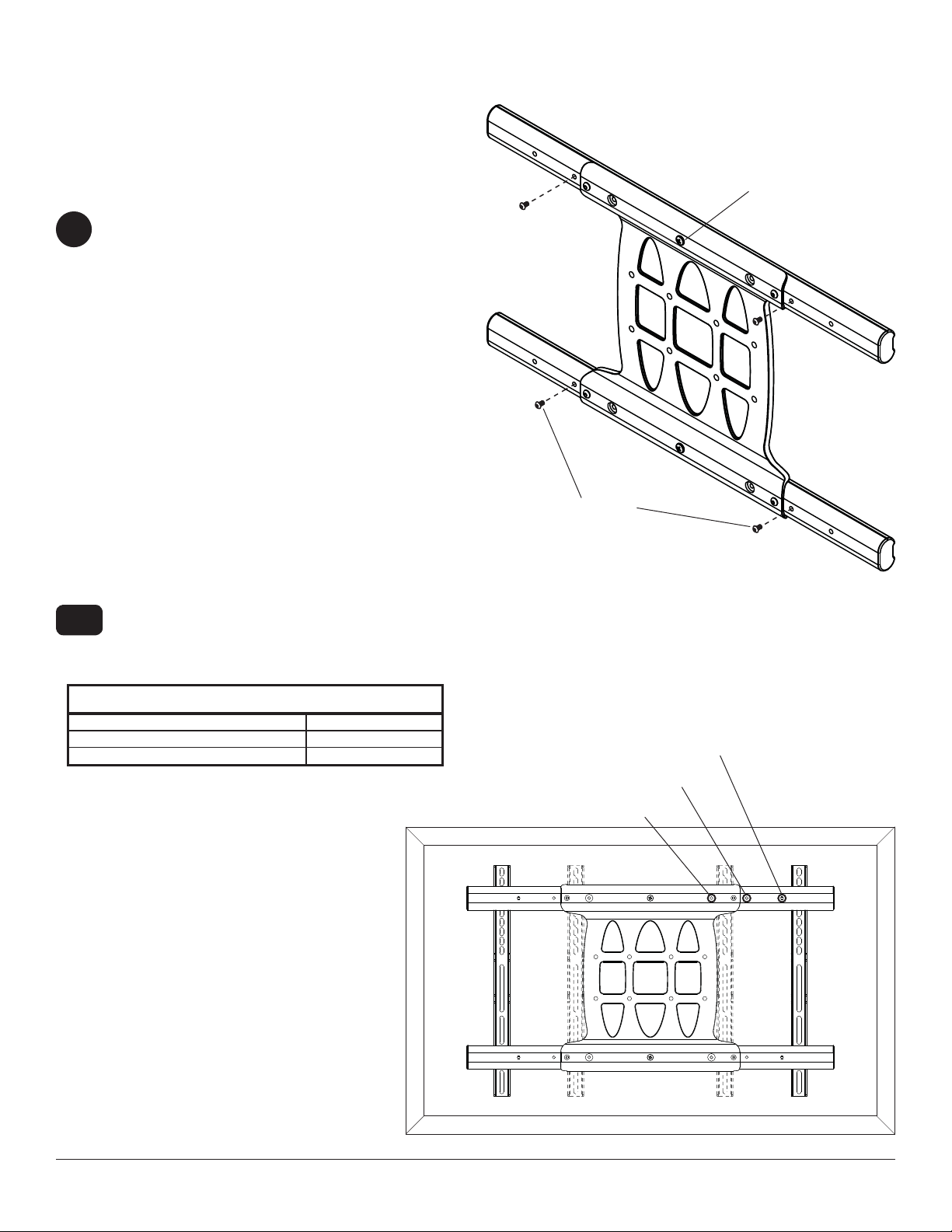
Attach the mounting brackets (J), open end of notch facing downward, to the left tilt bracket with two
9
1/4-20 x 1/2 socket head screws (G) and two 1/4-20 nuts (H) as shown in fi g. 9.1. Adjust the position of the
enclosure (A) to your desired location and tighten the four 1/4-20 x 1/2 socket head screws (G) using 4mm allen
wrench (L).
H
G
A
LEFT TILT BRACKET
fi g. 8.2
fi g. 9.1
16 of 22
2016-09-07 SHEET #: 180-9091-1
Page 17

Installing Tilt Brackets
WARNING
• Tighten screws so adapter brackets are fi rmly attached. Do not tighten with excessive force. Overtightening
can cause stress damage to screws, greatly reducing their holding power and possibly causing screw heads to
become detached. Tighten to 40 in. • lb (4.5 N.M.) maximum torque.
• If screws don't get three complete turns in the display inserts or if screws bottom out and bracket is still not tightly
secured, damage may occur to display or product may fail.
To prevent scratching the display, set a cloth on a fl at, level surface that will support the weight of the display. Place
10
display face side down. If display has knobs on the back, remove them to allow the adapter brackets to be attached. Place adapter brackets on back of display, align to holes, and center on back of display as shown below.
Attach the adapter brackets to the back of the display using the appropriate combination of screws, multi-washers,
and spacers as shown in fi gure 10.1.
NOTE: Top and bottom mounting holes on display must be used for attaching brackets.
NOTE: Be sure to attach tilt brackets with tilt locking screws facing outward as shown below. Verify that all holes
are properly aligned, and then tighten screws using a phillips screwdriver.
X
TILT LOCKING SCREWS
FACE OUT
MULTI-WASHER
CENTER BRACKETS
VERTICALLY ON BACK
OF DISPLAY
NOTE: "X" dimensions should be equal.
MEDIUM HOLE FOR M5 SCREWS
SMALL HOLE FOR M4 SCREWS
LARGE HOLE FOR M6 SCREWS
X
Notes:
• The number of fasteners used will vary,
depending upon the type of display.
• Multi-washers and spacers may not
be used, depending upon the type of
display.
• Use the corresponding hole in the multi-
washer that matches your screw size as
shown.
17 of 22
2016-09-07 SHEET #: 180-9091-1
Page 18

10-1
Begin with longer length screw, hand thread through multi-washer, tilt bracket and spacer in that order into display
as shown below. Screw must make at least three full turns into the mounting hole and fi t snug into place. Do not
over tighten. If screw cannot make three full turns into the display, select a longer length screw from the baffl ed
fastener pack. Repeat for remaining mounting holes, level brackets and tighten screws.
DISPLAY
MULTI-WASHER
SPACER
TILT BRACKET
If you have any questions, please call Peerless customer care at 1-800-865-2112.
fi g. 10.1
SCREW
18 of 22
2016-09-07 SHEET #: 180-9091-1
Page 19

Wireless Receiver Setup
Insert the sub panel assembly into the wireless receiver enclosure (A) above the foam pads as shown. Push
11
the sub panel assembly towards the rear of the until it makes contact with the back wall and the bottom of the
enclosure .
SUB P ANEL
ASSEMBLY
FOAM PADS
Insert an extension cord (not included) through the cord access hole in the bottom of the enclosure as shown. Plug
12
entension cord into the triple tap grounded outlet.
A
EXTENSION CORD
CORD ACCESS
HOLE
19 of 22
TRIPLE T AP
GROUNDED OUTLET
2016-09-07 SHEET #: 180-9091-1
Page 20

Insert the power cord from your display through the cord access hole in the bottom of the enclosure as shown. Plug
13
the power cord into the triple tap grounded outlet. Coil up the excess cord and secure with a cable tie (E). Store
excess cord inside enclosure.
DISPLAY POWER
CORD
CORD ACCESS
HOLE
Remove the tie from the IR receiver and insert the
14
end through the cord access hole in the bottom of the
enclosure as shown.
IR RECEIVER
Position the IR receiver on the front of the display
15
within line of sight of your remote as shown. Remove
the adhesive backing from the IR receiver eye and
attach to the display. Coil up the excess cord near
the wireless receiver enclosure and secure with a
cable tie (E). Store excess cord inside enclosure.
IR RECIEVER
20 of 22
2016-09-07 SHEET #: 180-9091-1
Page 21

Insert your component cable(s) (HDMI shown)
16
10
from your display through the cord access hole in
the bottom of the enclosure as shown and plug into
the wireless receiver. Coil up the excess cord and
secure with a cable tie (D). Store excess cord inside
enclosure.
COMPONENT
CABLE
17
Plug the wireless receiver power cord back into the
wireless receiver. Position the wireless receiver
into the enclosure as shown, then close the elosure
door. Door may be locked with key provided if
desired.
WIRELESS
RECEIVER POWER
CORD
Place the IR receiver and component cords inside
18
the cable management sheath (I) by pushing the
cables through the slit in the sheath. NOTE: The
sheath may need to be trimmed to length before
installing cords.
I
Plug extension cord into power source.
19
To complete the installation of your wireless system, please refer to the HD Flow™ User's Manual and the HD
Flow™ Install Guide included.
21 of 22
All other brand and product names are trademarks or registered trademarks of their respective owners.
Peerless-AV® is a registered trademark of Peerless Industries, Inc. All rights reserved.
2016-09-07 SHEET #: 180-9091-1
© 2012 Peerless Industries, Inc.
Page 22

WARRANTY
1 YEAR LIMITED WARRANTY
The HDS-OWK-300 is distributed by Peerless Industries, Inc. using the highest quality components and technology available.
The Product is warranted to be free from defects in material and workmanship, given normal use and care, for 1 Year from the
original purchase date with proof of purchase. Please retain a copy of your receipt as you will need this to obtain warranty work.
We will repair or replace the product which fails as a result of such a defect during the warranty period. The accessories are not
covered by this warranty.
This warranty is the customers’ exclusive remedy for product defect and does not apply to:
• Any modifi cations made to the product in any way by the customer
• Attachments to the product by the customer that causes product damage
• Any product which the seals/and or serial numbers and/or logos have been broken, removed, or tampered with, defaced, or
altered in any manner
• Damage caused by abuse, misuse, accident, water, or theft
• Physical damage
• Loss of the Accessories
Except as stated above, Peerless Industries, Inc. makes no express or implied warranties as to
any product, in Particular, makes no warranty of merchantability or fi tness for any particular purpose. Peerless Industries, Inc.
shall not be liable for consequential or incidental damages arising from any product defect. Our liability is limited to replacement
of any defective product as stipulated under the warranty conditions. Peerless Industries, Inc. expressly disclaims all warranties
not satisfi ed in this limited warranty. Any implied warranties that may be imposed by law are limited to the terms of this limited
warranty.
CONTACT INFORMATION
Customer Care
Need help with installation or set up? Call Peerless-AV Customer Care
1-800-865-2112 (available 7:00am- 7:00pm CST, Monday - Friday), or email us at info@peerless-av.com.
Peerless -AV
2300 White Oak Circle
Aurora, IL 60502 USA
www.peerless-av.com
22 of 22
2016-09-07 SHEET #: 180-9091-1
 Loading...