

Page 1
560M
Installation Instructions for Motor Torque
Module (MTM) in a 4848 Reactor Controller
Warning: The Motor Torque Module can only be used in
conjunction with a Motor Control Module (MCM). The
MCM must be installed before installation of the Motor
Torque Module. For Motor Control Module installation,
see Field Installation Manual 555M.
Meter Installation in 4848 Reactor
Controller
1. Unplug the power cord of the 4848 Controller.
Remove the (2) screws located on the top/front
cover at the rear corners of the controller. Gently lift the cover forward, which is hinged at the
bottom, taking care not to apply tension on any
internal wiring.
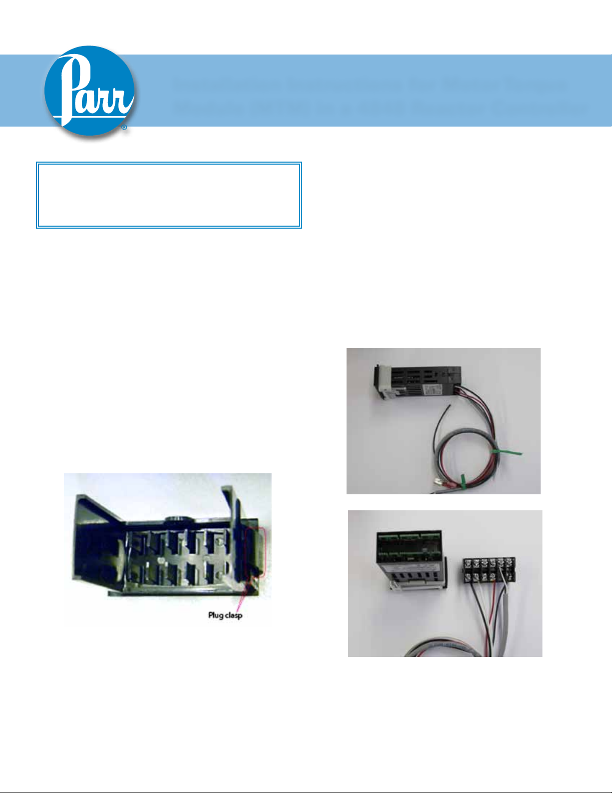
2. If applicable, remove and discard the black hole
plug on the sloped front panel above the “PRESSURE” or “TEMPERATURE” text. This can be
done by pinching the clasps on the back of the
plug from the inside of the front plate. Place
“MOTOR OUTPUT” label over existing text.
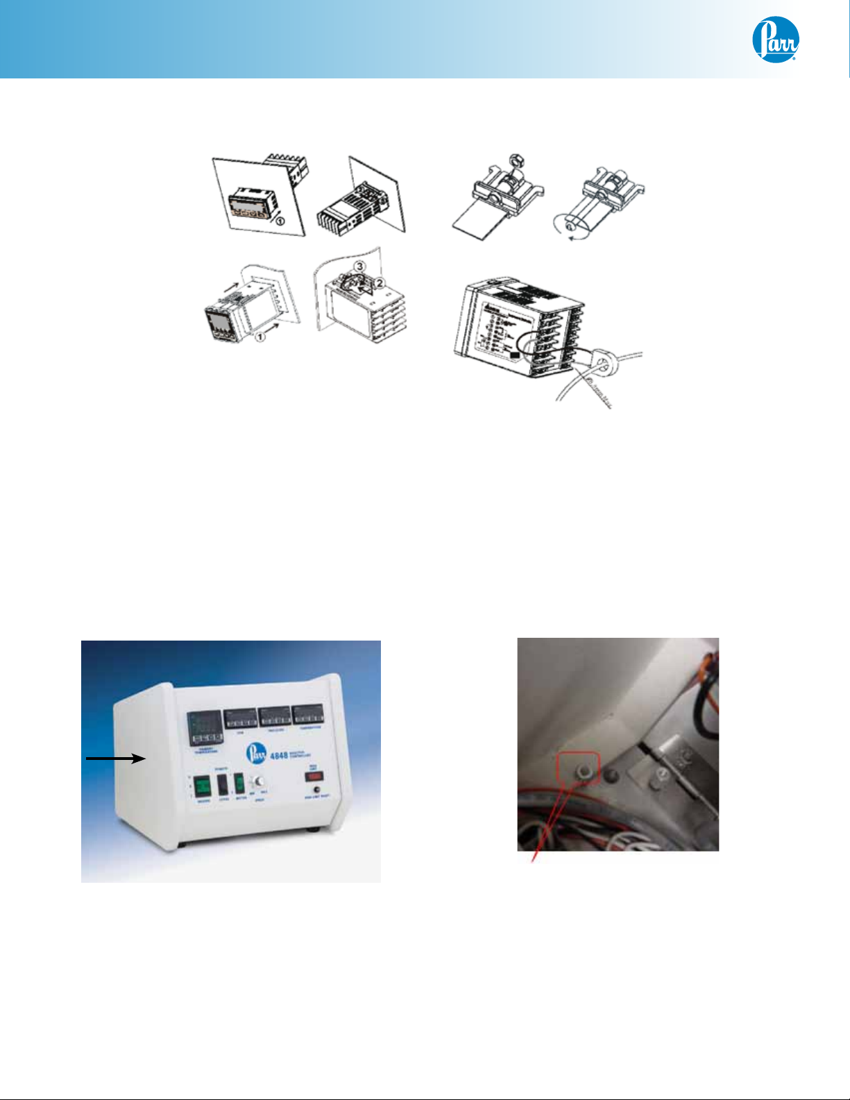
3. Insert the MTM module (2084E) through the
panel cutout, from outside in, making sure the
rubber gasket is on the outside of the controller
front panel. (If wires are preinstalled, remove the
terminal connector by releasing the tabs on the
sides of the module and gently pulling the terminal connector off. Reference photos below.) Slide
the white mounting bracket onto the module with
the mounting screws pointing towards the front
panel. Slide the mounting bracket forward until
it touches the controller panel. The clasps on the
mounting bracket should align with the groves
on the module. Gently tighten the screws until
the module is held into place. (If removed, reattach the terminal connector.)
Terminal Connector Removal
Page 2
MTM Installation
Meter Installation in 4848 Reactor Controller (Continued)
Meter Installation Diagram
Side Panel Removal
The left side panel should be removed to get access
to the isolation board. This is the panel on the left
hand side of the controller when looking at it from
the front.
Panel to be Removed
This will require loosening the four nuts on the side
panel using a nut driver (two on the bottom and two
on the back), removing the top cross brace, and then
pulling the panel away from the chassis.
Bottom Nut on Side Panel
2
Parr Instrument Company
Page 3
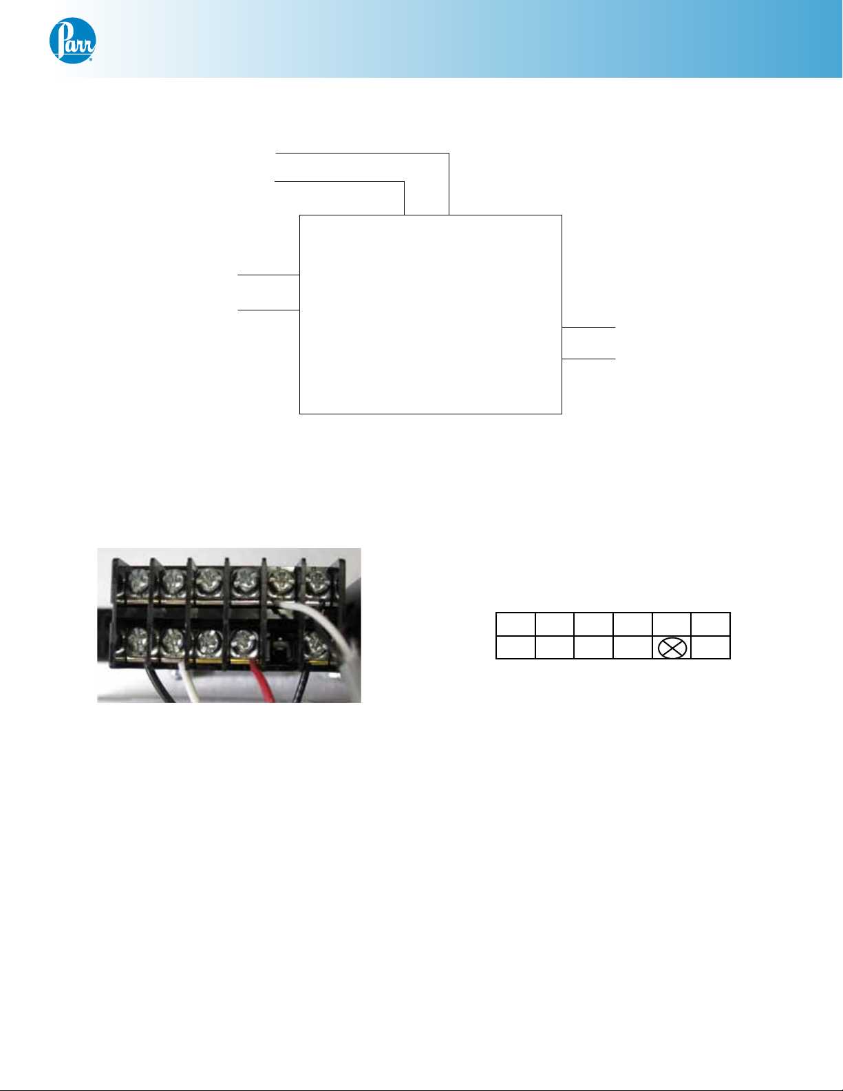
Wiring Installation in 4848 Reactor Controller
6-BLACK -
1-RED
6
2-BLACK
-
+
5-WHITE +
2
1
2084E
MOTOR OUTPUT DPM
3-WHITE
4-BLACK
4
12
11
100-240 VAC
POWER
RS485
MTM Installation
Wiring Diagram for 2082E Meter
Picture of MTM Meter 2084E Pin Out
7 8 9 10 11 12
1 2 3 4 5 6
2084E Pin Out
(Pin 5 is blank)
www.parrinst.com
3
Page 4

MTM Installation
Wiring Installation in 4848 Reactor
Controller (Continued)
1. Locate wire 1 (red) from the package. Take the
stripped end of this cable and attach it to the
2084E meter. The meter’s pins are labeled 1-12,
as shown. Attach this wire in position 4.
The other end has the 858E2 piggyback attachment which connects to the local/remote switch
in the middle position.
Pull out this quick disconnect terminal connector and attach it to the male connection on the
858E2 piggyback.
Plug the 858E2 piggyback onto the local/remote
switch in the middle position.
that has both ends stripped, and attach one end
to the 2084E meter. White wire #5 to terminal
#11 and black wire #6 to terminal #12. (This may
already be connected for your convenience.)
The other end of the white wire #5 attaches to
terminal block position #4 and the black wire #6
attaches to terminal block position #3.
Note: The terminal block position can be opened up
using a small flat head screw driver to release the
tension from the spring inside the block so you can
press the wire against the spring.
858E2
Piggyback
Local / Remote Switch (back view)
2. Locate wire 2 (black). The stripped end of the 2
wire cable attaches to the 2084E meter in position 6. The other end has a snap spade terminal
on it. This attaches to the 1588E isolation board.
Wago Terminal Block
4. Find the remaining black wire #4 from the kit and
attach one end to pin 1 on the 2084E meter. Take
care not to apply too much torque which could
cause the wire to break. (This may already be
connected for your convenience.) The other end
attaches to terminal block position #5.
5. Find the remaining white wire #3 from the kit
and attach one end to pin 2 on the 2084E meter.
Take care not to apply too much torque which
could cause the wire to break. (This may already
be connected for your convenience.) The other
end attaches to terminal block position #2.
Final Steps
Notice that the isolation board has its pins numbered 1-10. Attach the snap spade terminal to
position 9.
3. Find the 2 wire cable with white and black wires
4
Parr Instrument Company
Page 5

MTM Installation
Reattach the side panel by slipping it back on and
tightening the nuts.
Close the controller and replace the two screws on
the top plate. Plug the 4848 controller back in, and
turn it on. The MTM display should read approximately zero when the motor is not turning. It is
useful to check that the settings on the display are
set correctly. Check the settings in this installation
guide against the settings on the controller.
Calibrating the MTM
1. 1. Turn the knob to zero, flip the local/remote
switch to “local”, and turn the motor switch on.
The MTM should show a value of zero. If it does
not, adjust the “tPoF” setting (press set and then
return until it shows tPoF) until it does read zero.
2. Turn the knob to full. The MTM should show a
value of 100.
3. Flip the local/remote switch to “remote”, and
put in a setpoint equal to the maximum stirring
speed on the Motor Control Module display. The
MTM should show a value of 100.
Pin Outs:
2084E Color: Attaches to:
Pin 1 Black Terminal Block 5 (power)
Pin 2 White Terminal Block 2 (power)
Pin 3
Pin 4 Red local / remote switch
(bottom position) (signal)
Pin 5
Pin 6 Black isolation board (pin 9)
(signal)
Pin 7
Pin 8
Pin 9
Pin 10
Pin 11 White Terminal Block 4 (RS-485)
Pin 12 Black Terminal Block 3 (RS-485)
Factory Default Settings - MTM
www.parrinst.com
5
Page 6

MTM Installation
Module
Keys command:
1. Press “SET” to select
2. Press return key move to next operation mode
3. Up/Down arrow keys to adjust value or select
type
Main Screen: SV = 100
Press return key and release
Operation
Mode
r-S Run Run/Stop
SP 1 Decimal point position
LoC OFF
Press and hold down “SET” for 5-sec
Operation
Mode
InPt v10 Input type (v5 = 0-5V,
tP-H To be de-
tP-L 0 Lower-limit temperature
CTRL ON/OFF Control mode (ON/OFF,
S-HC Heat Heat/Cool control
ALA1 0 Alarm mode
SALA OFF System alarm
CoSH ON Communication write
C-Sl ASCII Format type
C-no See note** Communication address
bPS 9600 Communication baud
Len 7 Data length setting
Select
type/value
Select
type/value
termined*
Comment
Lock mode (lock all
keys or only up/down
arrow able to use)
Comment
v10 = 0-10V, nA0 =
0-20mA, nA4 = 4-20mA,
nV =0-50mV)
Upper-limit range
range
MANUAL, PID and PID
PROG)
function that able to use
set point from software
rate
Operation
Mode
PrtY Even Parity bit setting
StoP 1 Stop bit setting
* For 90VDC motor, 115VAC, tP-H = 142.9
For 180VDC motor, 230VAC, tP-H = 120.4
For 90VDC motor, 230VAC, tP-H = 153.2
** First available communication port (3 or 4)
Press “SET” and release
Operation
Mode
HtS 0 Hysteresis
TPoF 0 Inaccuracy adjustment
CrHI 0 Analog output low
CrLo 0 Analog output high
Select
type/value
Select
type/value
Comment
Comment
6
Parr Instrument Company
Page 7

This page intentionally left blank.
MTM Installation
www.parrinst.com
7
Page 8

Revision 08/21/12
 Loading...