

Page 1
Motor Control Module (MCM)
for the 4848 Reactor Controller
Meter Installation in 4848 Reactor Controller
1. Unplug the power cord of the 4848 controller. Re-
move the (2) screws located on the top/front cover at
the rear corners of the controller. Gently lift the cover
forward, which is hinged at the bottom, taking care
not to apply tension on any internal wiring.
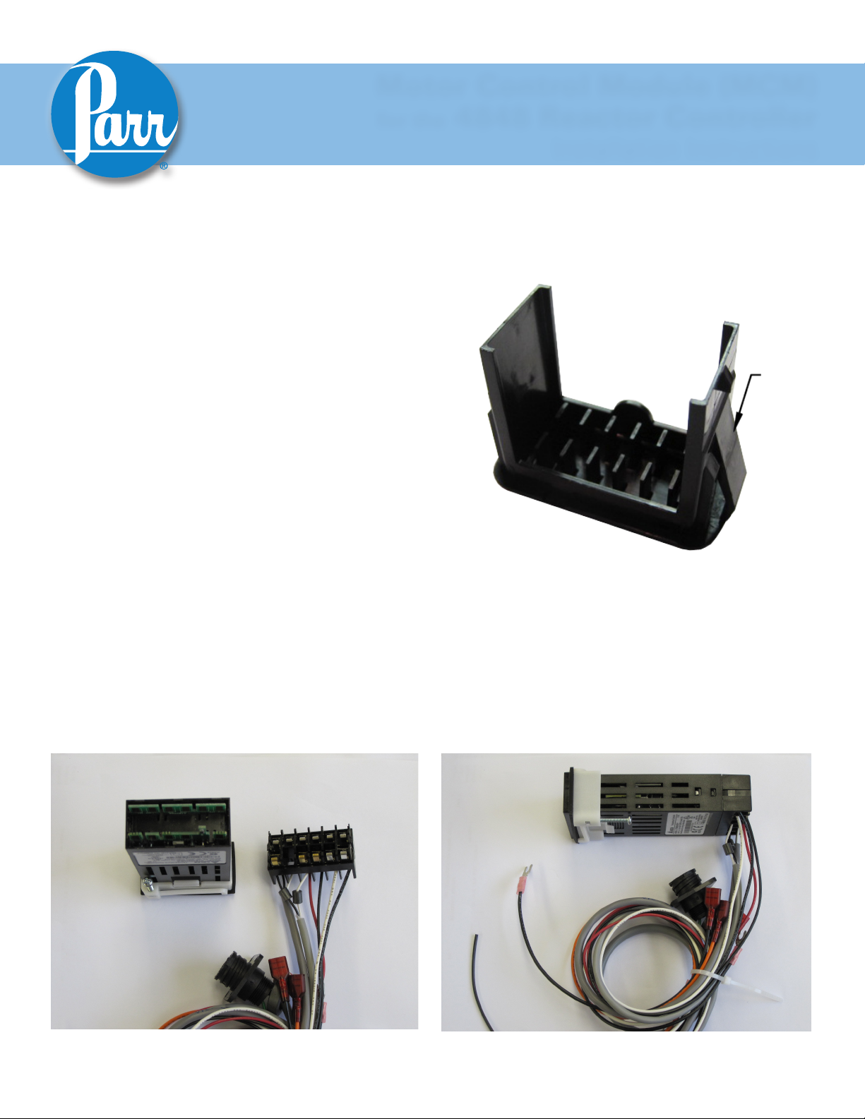
2. If applicable, remove and discard the black hole plug
on the sloped front panel above the "RPM" text. This
can be done by pinching the clasps on the back of the
plug from the inside of the front plate.
599M
Installation Instructions
PLUG
CLASP
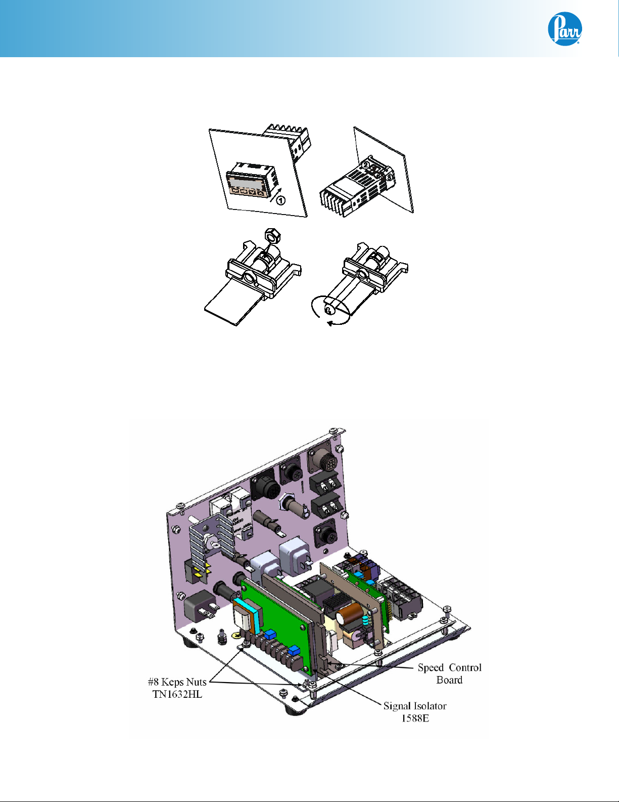
3. Insert the MCM (2084E) through the panel cutout,
from outside in, making sure the rubber gasket is
on the outside of the controller front panel. (If wires
are preinstalled, remove the terminal connector by
releasing the tabs on the sides of the module and
gently pulling the terminal connector off. Reference
photos below.) Slide the white mounting bracket
onto the module with the mounting screws pointing
towards the front panel. Slide the mounting bracket
forward until it touches the controller panel. The
clasps on the mounting bracket should align with the
groves on the module. Gently tighten the screws until the module is held into place. (If removed, reattach
the terminal connector.)
2100E Black Hole Plug
Terminal Connector Removal
Page 2
MCM Installation
Meter Installation in 4848 Reactor Controller (Continued)
Meter Installation Diagram
4. Mount the 1588E Signal Isolator, orient as shown, using the (2) TN1632HL keps nuts supplied.
4848 Inside View
2
Parr Instrument Company
Page 3
MCM Installation
Wiring Installation in 4848 Reactor Controller
1. If applicable, remove the black hole plug on the back of the controller labeled RPM INPUT. This can
be done by pinching the clasps on the back of the plug from inside the back panel.
2. Insert the 4-pin receptacle (494E), on the A2106E harness, into the RPM input hole from the inside
out. Slide the ring terminal, from the A2106E green wire, onto one of the mounting studs. Mount the
receptacle using the (2) #4 keps nuts provided.
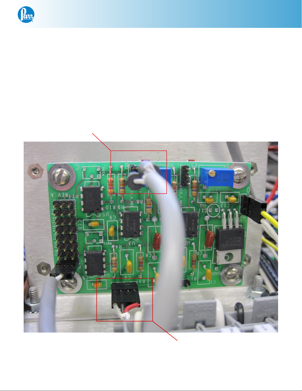
3. Locate the A1695E excitation board as shown.
TACH OUT
A1695E Excitation Board
TACH IN
www.parrinst.com
3
Page 4

MCM Installation
Wiring Installation in 4848 Reactor Controller (Continued)
4. Attach the 4-pin edge connector from the
A2106E to the “Tach In” (slot A). Align the empty
spot on the edge connector to the empty pin on
the “Tach In” of the A1695E excitation board.
Reference the A1695E Picture on page 3.
5. Find the 2 wire cable, black and white wires with
one end stripped and the other end has a 3 pin
edge connector as shown, and plug the 3-pin
edge connector to the “Tach Out” (slot A). The
Orientation of the black wire does not matter;
the connection can be plugged in either way.
6. The stripped end of the 2 wire cable attaches
to the 2084E meter. Take care not to apply too
much torque which could cause the wire to
eventually break. The meter’s pins are labeled
1-12, as shown. The black wire from the A2106E
harness attaches to pin 6, and the white wire attaches to pin 4. (This may already be connected
for your convenience.)
TACH OUT
TACH IN
7. Find the 2 wire cable with white and black wires
that has both ends stripped, and attach one end
to the 2084E meter. White wire #3 to terminal
#11 and black wire #4 to terminal #12. (This may
already be connected for your convenience.)
The other end of the white wire #3 attaches to
terminal block position #4 and the black wire #4
attaches to terminal block position #3.
Note: The terminal block position can be opened
up using a small flat head screw driver to release
the tension from the spring inside the block so you
can press the wire against the spring.
7 8 9 10 11 12
1 2 3 4 5 6
2084E Pin Out
Wago Terminal Block
4
Parr Instrument Company
(Pin 5 is blank)
Page 5

MCM Installation
Wiring Installation in 4848 Reactor Controller (Continued)
8. Find the remaining black wire #2 from the kit and attach one end to pin 1 on the 2084E meter. Take
care not to apply too much torque which could cause the wire to break. (This may already be connected for your convenience.) The other end attaches to terminal block position #5.
9. Find the remaining white wire #1 from the kit and attach one end to pin 2 on the 2084E meter. Take
care not to apply too much torque which could cause the wire to break. (This may already be connected for your convenience.) The other end attaches to terminal block position #2.
10. Find the black wire #5 (with one end stripped and one end has a snap spade terminal connector)
and attach the stripped end to the 2084E meter terminal #9. (This may already be connected for your
convenience.) The snap spade end attaches to the 1588E signal isolator terminal #5.
11. Find the red wire #6 (with one end stripped and the other end having a snap spade terminal attached) and attach the snap spade connector to terminal #6 on the 1588E signal isolator. Attach the
stripped end to terminal #10 on the 2084E Meter.
12. Find the black wire #7 (one end has a snap spade terminal the other has a female quick disconnect
terminal) and attach the snap spade connector to terminal #9 on the 1588E signal isolator. The female quick disconnect attaches to terminal F- on the speed control board.
13. Find the red wire #8 and attach the snap spade connector to terminal #10 on the 1588E signal isolator. Attach the female quick disconnect to the top position on the local/remote switch.
14. Disconnect the orange wire #10 at the speed control board terminal P2 and attach to the bottom position on the remote/local switch.
15. Find the orange wire #9 and attach one end to terminal P2 on the speed control board. The other end
attaches to the middle position on the local/remote switch.
16. Find the black wire #11 (with one end stripped and the other end has a snap spade terminal attached) and attach the snap spade connector to terminal #4 on the 1588E signal isolator. Attach the
stripped end to terminal block #1.
17. Find the white wire #12 (with one end stripped and the other end has a snap spade terminal attached) and attach the snap spade connector to terminal #1 on the 1588E signal isolator. Attach the
stripped end to terminal block #2.
C
D
E
A
B
Snap Spade
A
E
D
C
Quick Disconnect Terminals
www.parrinst.com
5
Page 6

MCM Installation
Wiring Installation in 4848 Reactor Controller (Continued)
Pin Outs:
2084E Color: Attaches to:
Pin 1 Black Terminal Block 5
Pin 2 White Terminal Block 2
Pin 3
Pin 4 White A1695E Excit Board
Pin 5
Pin 6 Black A1695E Excit Board
Pin 7
Pin 8
Pin 9 Black 1588E Terminal 5
Pin 10 Red 1558E Terminal 6
Pin 11 White Terminal Block 4
Pin 12 Black Terminal Block 3
1588E Color: Attaches to:
Pin 1 White Terminal Block 2
Pin 2 Jumper
Pin 3 Jumper
Pin 4 Black Terminal Block 2
Pin 5 Black 2084E Terminal 9
Pin 6 Red 2084E Terminal 10
Pin 7
Pin 8
Pin 9 Black Speed Control F-
Pin 10 Orange
Pin 1 on 115V
Pin 3 on 230V
Pin 4 on 115V
Pin 2 on 230V
Local/Remote Switch
Top Position
Final Steps:
Close the controller and replace the two screws on the top plate. Plug the 4848 controller back in, and turn it on.
The RPM display should read zero when the motor is not turning.
It is useful to check that the settings on the display are set correctly. Check these against the defaults listed in the
back of these instructions.
Motor Control Module (MCM) Wiring Schematic
FROM A2106E RPM INPUT HARNESS
TO TERMINAL
BLOCK
2065E
REF
115V
JUMPER SETTING
1
N
2
3
4
L
IN
1588E
SIGNAL
ISOLATER
OUT
12
11
- 5
+ 6
10
1
N
2
3
4
1
2
3
9
4
1588E
SIGNAL
ISOLATER
L
230V
JUMPER SETTING
N
1588E
SIGNAL
ISOLATER
L
IN
OUT
IN
OUT
- 5
5 OUT
+ 6
6
7
9
8
10
- 5
+ 6
REF
9
10
1 - WHITE
2 - BLACK
3 - WHITE
4 - BLACK
BLACK
RED
2
N
1
L
4 +
6 11 +
12 9 -
5
10 +
6
7
F -
P1
CONTROL BOARD
P3
9
P2
8
T
9
M
B
10
10
2084E
IN
RPM DPM
RS485
A1250EEE OR
A1220EEE
DC SPEED
REF
REMOTE
LOCAL
ADJUSTABLE
POTENTIOMETER
6
Parr Instrument Company
REF
Page 7

MCM Installation
Factory Default Settings
MCM Module
Keys command:
1. Press “SET” to select
2. Press return key move to next operation mode
3. Up/Down arrow keys to adjust value or select type
Main Screen: SP = 0
Press return key and release
Operation Mode Select type/value Comment
r-S Run Run/Stop
SP 0 Decimal point position
LoC OFF Lock mode (lock all keys or only up/down arrow able to use)
Out1 - (read-only) Motor output %
Press and hold down “SET” for 5-sec
Operation Mode Select type/value Comment
InPt v5
tP-H 2206 Upper-limit range
tP-L 0 Lower-limit temperature range
CTRL PID Control mode (ON/OFF, MANUAL, PID and PID PROG)
S-HC Heat Heat/Cool control
ALA1 0 Alarm mode
SALA OFF System alarm
CoSH ON Communication write function that able to use set point from software
C-S1 RTU Format type
C-no 2 Communication address
bPS 9600 Communication baud rate
Len 8 Data length setting
PrtY Even Parity bit setting
StoP 1 Stop bit setting
Input type
(v5 = 0-5V, v10 = 0-10V, nA0 = 0-20mA, nA4 = 4-20mA, nV =0-50mV)
Press “SET” and release
Operation Mode Select type/value Comment
At OFF Auto Tuning ON/OFF
PID0 0 The 0th PID Parameter
SV 0 The 0th SV
P0 170 Proportional control
C0 1 Integral control
D0 0 Derivative control
CoF0 0 Integral value
HtPd .5 Heat/Cool cycle control
tPoF 0 Inaccuracy adjustment
www.parrinst.com
7
Page 8

599M R02 Revision 11/08/13
 Loading...