

Page 1
Parr Magnetic Drives
Operating Instruction Manual
234M
Page 2
Parr Magnetic Drives
Preface 3
Description 3
Related Instructions 3
Light Duty A1120HC/A2140HC/A2150HC Series 3
Heavy Duty Drives A1180HC/A1750HC/A2160HC/A2170HC
Series 3
Extra Heavy Duty Drives A1180HC2/A1750HC2/ A2160HC2/
A2170HC2 Series 3
Characteristics 3
Servicing the Magnetic Drive 4
The O-Ring Seal 5
Servicing the Outer Drive 5
Disassemble the Outer Drive 5
Reassemble the Outer Drive 5
Removing and Installing Mag netic Drives with Flat Gasket
Seals 6
Removing and Installing Mag netic Drives with Olive Seals 6
Servicing the Cooling Sleeve 6
Older Models 6
Installing the Stirrer Shaft on a Footless Magnetic Drive 6
Gasket Material Designations 7
Specifications 8
Magnetic Drives With Lower Foot Bearing 8
Magnetic Drives Without Lower Foot Bearing (Footless) 9
Drawings and Parts Lists 10
A1120HC6 Magnetic Drive 10
A1180HC Magnetic Drive 11
A1180HC5 Magnetic Drive 11
A1750HC Magnetic Drive 12
A1750HC2 Magnetic Drive 12
A2140HC/A2140HC2 Magnetic Drive 13
A2150HC Magnetic Drive 13
A2160HC Magnetic Drive 14
A2160HC4 Magnetic Drive 14
A2170HC Magnetic Drive 15
A2170HC2 Magnetic Drive 15
Customer Service
Questions concerning the installation or operation
of this instrument can be answered by the Parr
Customer Service Department:
Accessories 7
Drive Maintenance Tools 7
Spanner Wrenches 7
1-309-762-7716 • 1-800-872-7720
Fax: 1-309-762-9453
E-mail: parr@parrinst.com
http://www.parrinst.com
2
Parr Instrument Company
Page 3
Parr Magnetic Drives
Preface
Description
The principle operation of Parr magnetic drives provides for attaching the stirrer shaft to an inner set of
magnets. This inner assembly is then surrounded by
the drive housing that seals to the reac tor head allowing pressurization without leakage. A second set of
magnets is then mounted around the sealed hous ing.
The outer magnetic assembly is then coupled to a
motor drive system to provide rotation. The coupling
force be tween the two sets of magnets permits the
shaft to turn at the rpm selected for the motor.
Parr magnetic drives are available in three torque ratings: 16 in-lb, 60 in-lb, and 120 in-lb (1.8 Nm, 6.6 Nm, and
13.2 Nm). The drives are also available with two types
of shafts; one that requires a lower support bushing and
one that is “footless.” The Model number assigned to
each drive depends upon the above selection as well as
the type of connec tion used to mount the drive into the
re actor head and the type of upper cap used for connection to the overarm and motor drive system.
normally ade quate to carry the usual stirring loads developed in a Parr “Mini” reactor and the one and two
liter bench top and floor stand models with general
purpose stir rers. The outer magnetic drive housing
measures 2¼” O. D. x 3½” high.
Heavy Duty Drives A1180HC/A1750HC/ A2160HC/A2170HC Series
This is a 6-pole model with 60 inch pounds of coupling
torque to handle most of the stirring loads arising in
Parr one and two liter, and one, two, and 5 gallon floor
stand reactors with heavy duty stirrers. The drive housing meas ures 3½” O. D. x 4½ high.
Extra Heavy Duty Drives A1180HC2/ A1750HC2/ A2160HC2/A2170HC2 Series
This is the largest of the three Parr drives. It consists of
two, 6-pole mag nets assemblies mounted end-to end
to provide 120 inch-pounds of coupling torque for use
as an alternative drive for large Parr reactors when a
strong drive is required to handle very high viscosity
loads. The drive housing measures 3½” O.D. x 6½” high.
Related Instructions
The following Parr publications are available to
further your understanding of this equipment and its
component parts:
No. Description
201M Limited Warranty
Parr Magnetic Drive Service Instructional Video
Go to http://youtu.be/zjBw5l_yBHw to view a video
supplement to aid users with performing routine mainte-
nance on Parr Instrument Company’s Magnetic Drives.
Light Duty A1120HC/A2140HC/A2150HC Series
This is the smallest of the three drives. It is a 4-pole
model with 16 inch-pounds coupling torque. This is
Conversion from a smaller to a larger drive or to a
“footless” drive may require modification to the standard over/arm and motor configuration. It may require
a different head.
Note: Unless otherwise indicated, the instructions
given here apply to all of the above units.
Characteristics
Parr magnetic drives require minimal attention or
maintenance. The spe cially designed neodymiumironboron permanent magnets used in these drives have
excellent temperature sta bility and can be relied upon
to operate for long periods with little or no flux degradation. When properly installed, the outer rotor should
spin freely and the inner (driven) unit should follow
without slippage, providing a high torque stirring
action. The magnets in both inner and outer rotors are
epoxy bonded to their iron cores.
Care must be taken to prevent these components from
being heated above 100 °C, which would destroy the
bond ing of the magnet assemblies. To pre vent overheating, each magnetic drive has an attached cooling
sleeve through which a steady flow of cold water
should be fed during all vessel operations at temperatures above 100 ºC. Tubing connections for flowing
water connections are provided on each sleeve, and
a 10 foot length of tub ing is furnished to connect to a
water source.
www.parrinst.com
3
Page 4
Parr Magnetic Drives
Servicing the Magnetic Drive
All non-wetted rotating parts in Parr magnetic drives
are permanently lubricated and do not require servicing during normal operation. During operation, inspect
the magnetic drive for unusual noise or leakage. If
problems are encountered with these items take corrective action. The magnetic drive has internal bearings
and thrust washers which require replacement over
time due to physical wear. Excessive lateral or axial
play in the stirrer shaft is an indication of worn bearings or thrust washers. Labored rotation or excessive
debris inside the reactor cylinder also indicates a need
for maintenance. It’s difficult to recommend a timebased preventative maintenance interval for the drive
due to the wide spectrum of operating conditions encountered. The experience of the laboratory should be
used to guide the need for preventative maintenance.
It is advisable to check the drive from time to time for
evidence of leakage into the confined space between
the inner and outer rotors. This can be done without
removing the drive from the vessel head and does
not require complete disassembly. While performing
maintenance or rebuilding the drive, the PTFE o-ring
that seals the top plug should always be renewed if the
plug is removed. To inspect the drive:
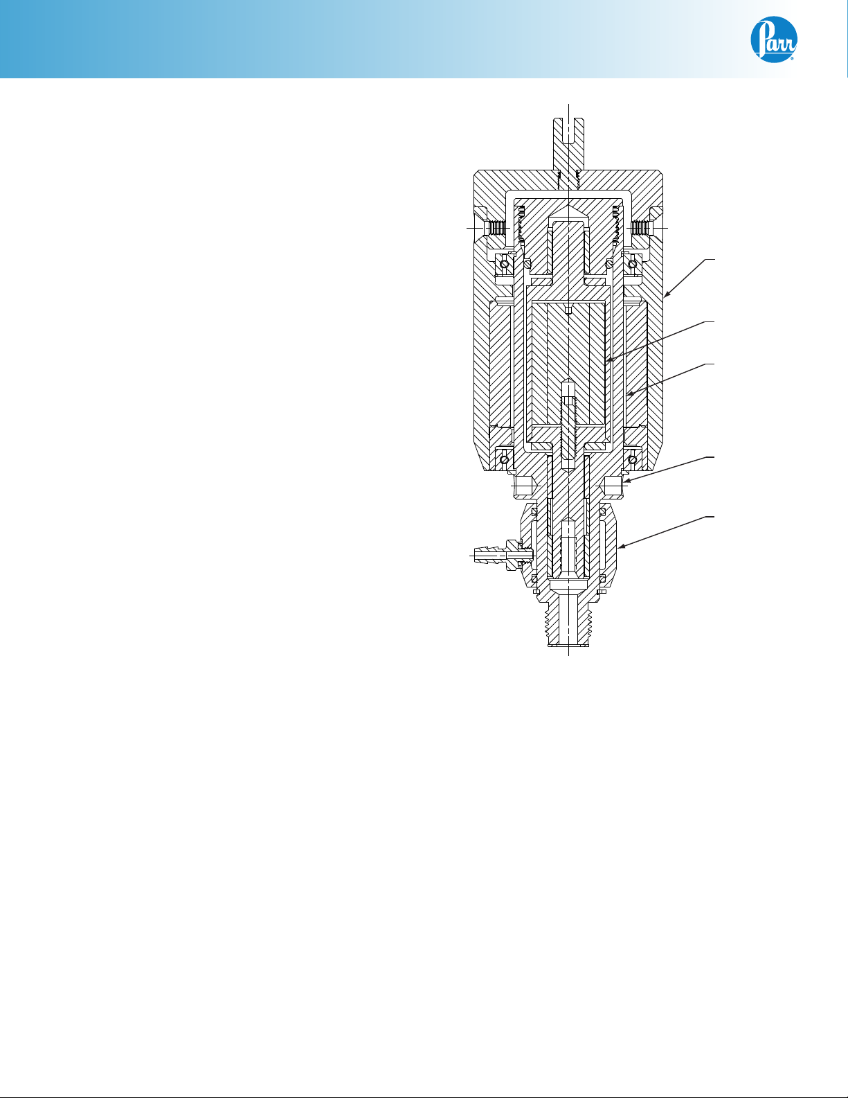
Outer Driving
Magnetic
Assembly
Inner Magnetic
Rotor
Non-Rotating
Inner Housing
Holes for
Pin Spanner
Wrench
Cooling
Sleeve
1. Remove the four socket head screws located near
the top of the outer housing and remove the top
cover from the housing. This will expose the plug
which aligns the inner rotor and carries the principle O-ring seal.
2. Unscrew the plug, using a 264AC5 face spanner inserted into the two holes at the top of the plug while
holding the rotor firmly with a 264AC3 or 264AC4
pin spanner inserted into one of the holes at the bottom of the assembly above the cooling sleeve. With
the plug removed, the sleeve bushing and thrust
washer at the top of the rotor will be exposed.
3. Check for any evidence of leakage past the O-ring
seal. If vapors from the reactor have produced
solid deposits in or around the rotor housing, the
deposits will have to be removed to keep them
from destroying the slide bushings or jamming the
rotor. If cleaning is not re quired, replace the plug
and close the drive.
4. If cleaning is required, the inner ro tor can be
removed without removing the entire drive from
the bomb head. To remove: Remove propeller from
shaft. For vessels with a one piece shaft, the shaft
can be used to push the rotor out of the stirrer
housing. For vessels with a lower coupled shaft assembly, the shaft will need to be disconnected from
Parr Magnetic Drive
the upper shaft. In the larger magnetic drives, the
rotor can be removed by attaching a threaded (5/16
– 24) rod to the top of the inner rotor and pulling up
from the top of the housing.
The inner rotor is a laser-welded, sealed unit which
should require no mainte nance, but it can be damaged
by over heating as mentioned earlier. With the rotor
removed, it may be advisable to re place the three sleeve
bushings which guide the inner rotor. Two of these, plus
a spacer, are located deep in the mag netic drive housing.
The third sleeve bushing is held in the top plug. Although
these bushings can be pulled out with a wire hook or
scribe, removal is much easier using a specially designed bush ing removal tool (See Page 8). Simply screw
the threaded end of the removal tool into the bushing
until it is firmly en gaged, then pull out the bushing. The
spacer between the two bushings should slide out freely.
Remove the bottom bushing in the same manner.
4
Parr Instrument Company
Page 5

Parr Magnetic Drives
When replacing the bushings in the magnetic drive
housing, slide the parts into place carefully and be sure
to separate the two lower bushings with a spacer. A
specially designed bushing insertion tool is available
for this operation (See Page 8). Using the insertion tool,
slide a bushing onto the end of the tool with the longest
shank, then insert the tool with the bushing into the
opening in the rotor chamber and push it down until the
shoulder on the tool strikes the bottom of the chamber.
This will position the bushing properly. Then drop the
spacer into the opening and use the short end of the
installation tool to insert the upper sleeve bushing,
again pushing the tool downward until it strikes the
bottom of the plug. When properly installed, the top of
the upper bushing should be flush with the bottom of
the rotor chamber.
After cleaning the rotor and the chamber, install the
inner rotor as follows:
1. Set the lower thrust washer into posi tion so that it
will be available to cushion the rotor if it should accidentally slam into the bottom of the chamber.
2. Lower the rotor into the chamber slowly, but be
prepared to resist the strong pull of the outer
magnets during this operation. Use the same rod
employed when removing the rotor to resist the
strong pull during assembly.
3. Replace the upper sleeve bushing and the O-ring
in the top plug; insert the upper thrust washer; lubricate the threads with 424HC2 anti-seize lubricant
(careful not to get any on the O-ring) and screw the
top plug into place. Then replace the top cover and
secure it with the four socket head screws.
The O-Ring Seal
The O-ring, which seals the top plug in Parr magnetic
drives, is made of PTFE. If solvent attack becomes a
problem, the O-ring may have to be replaced with an
O-ring made of another material.
Servicing the Outer Drive
The outer drive is supported by two high quality sealed
ball bearings which do not require lubrication. Any oil
leak or noise from the bearing will indicate that the
seal or the bearing has failed and the bearing must be
replaced.
Disassemble the Outer Drive
1. Remove the four socket head screws located near
the top of the outer housing; then lift the cover
from the housing to expose the upper snap ring.
Peel the snap ring out of its groove with a small
screwdriver; slide it upward and remove it.
2. Take a firm grip on the outer drive housing and
pull it upward to separate the outer assembly from
the magnetic drive housing. The lower bearing may
not come out with the housing. If not, remove at
this time.
Reassemble the Outer Drive
1. Slide the lower spiral snap ring back into its
groove; then slide the lower ball bearing onto the
inner hous ing. The inner magnets should hold the
bearing at the middle of the housing.
2. Slide the outer drive assembly over the rotor,
thereby pushing the lower bearing down against
the lower spiral snap ring. Hold both parts firmly
during this step so that the magnets do not slam
the outer drive into place.
3. Insert the upper wave spring into its groove in
the outer drive housing and slide the ball bearing
into place against the wave spring, then anchor
the bearing by pushing the retaining snap ring
downward until it snaps into its groove above the
bearing. During this step sufficient pressure must
be applied against the snap ring and force the
wave spring downward and allow the snap ring to
drop bearing to force the wave spring down ward
and allow the snap ring to drop into its groove. This
can be done with a pair of screw drivers, using
alternating pressure on the snap ring. This must be
done carefully to be sure that the screw drivers do
not slip and damage the seals in the bearings. To
simplify the opera tion, Parr offers a magnetic drive
assem bly tool (Part No. 2086HC) consisting of a
properly sized cup which can be pushed downward
against the snap ring to force it into its groove.
There are cups on the 2086HC assembly tool to fit
both the small and larger Parr magnetic drives.
4. Replace the top cover and secure it with the four
socket head screws.
www.parrinst.com
5
Page 6

Parr Magnetic Drives
Removing and Installing Mag netic Drives with
Flat Gasket Seals
These magnetic drive assemblies can be removed
from the vessel head using the appropriate pin spanner wrench fur nished with the apparatus (See Table on
Page 8). First, unscrew the stirrer shaft from the inner
rotor, then insert the pin spanner into one of the holes
below the outer jacket and unscrew the drive as sembly
while holding the vessel head firmly. The cooling
sleeve can be held stationary when unscrewing the
drive from the head. The drive is sealed into the head
with a gasket which usually will remain in the head
when the drive is removed.
If the gasket appears to be in good condi tion, it can be
reused. If it is question able, replace with a new one.
Apply a lib eral coating of anti-seize lubricant to the
mounting threads of the drive body before screwing
the drive into the head. Tighten the drive firmly with
the pin spanner and screw the stirrer shaft into the
inner rotor to complete the assembly.
Removing and Installing Mag netic Drives with
Olive Seals
To remove these magnetic drive assemblies, unscrew
the stirrer shaft, then hold the bomb head firmly and
use the 739HC (1-5/16”) wrench furnished with the
appara tus to remove the drive by unscrewing the
gland nut located below the cooling sleeve. The cooling sleeve can be held stationary during this operation
to clear the nearby fittings as the drive is re moved.
These drives are sealed into the head by compression
from the gland nut onto a tapered 663HC olive. There
is no gasket in this gland. Remove and clean the olive
whenever the gland is removed.
Servicing the Cooling Sleeve
The cooling sleeves used on Parr mag netic drives have
two O-rings which seal the sleeve onto the stem of the
drive housing. These O-rings will have to be replaced
after long service or after ex cessive heating with no
water flowing through the sleeve . To replace the O-rings
it will be necessary to remove the drive assembly from
the head as de scribed above. After removing the drive,
rotate and pull off the cooling sleeve after removing the
clip ring, if present. The O-rings can now be removed
from the sleeve, but be careful not to scratch or damage
the O-ring grooves. Clean any accumulated lime deposits from the sleeve and insert new O-rings into the
grooves; then moisten the O-rings and slide the cooling
sleeve into place on the drive stem. The drive can now
be rein stalled in the head as described above.
Older Models
All series 4520 and 4530, one and two liter reactors built
before November, 1985 were equipped with A1120HC2
and A1120HC3 magnetic drives respectively. These
older models are similar to the present A1120HC style
except they have different mounting threads and different shaft lengths for attachment to the for mer 229HC
style head. All instructions given here for the current
A1120HC drive apply to these older models as well.
Installing the Stirrer Shaft on a Footless Magnetic Drive
Normally the stirrer shaft is simply screwed into the
inner magnetic rotor housing from the underside the
stirrer housing. There is no interference in magnetic
drive Series A1120HC, A1180HC or A1750HC to cause a
problem.
To install these drives, coat both sealing faces on the
663HC olive with anti-seize lubricant and set the olive
squarely in the head. Lubricate the threads on the
stem of the magnetic drive and screw the 664HC gland
nut onto the stem as far as it will go; then back it off
one-quarter turn. Lubricate the threads on the gland
nut and screw the drive assembly into the head, being
careful to maintain the one-quarter turn relationship
between the stem and the nut. Tighten the nut firmly
to complete the connection. Screw the stirrer shaft into
the drive from the underside of the head and check the
assembly by spinning the drive by hand. The stirrer
should turn freely without binding.
6
Parr Instrument Company
In the Series A2140/50HC, A2160HC and A2170HC
footless magnetic drives it is pos sible to trap the thrust
washer between the shoulder machined on the shaft
and the inner magnetic rotor housing. If this happens
there will be a large amount of run out in the shaft or
the shaft will be too long for the cylinder. This can be
prevented by first removing the outer magnetic drive
housing and the plug. Then use the shaft to push up
from the bottom the inner magnetic rotor housing and
installing the thrust washer on the stirrer shaft below
the machined shoulder so there is no interference from
the thrust washer. Screw the stirrer shaft and the inner
magnetic rotor housing parts together and reassemble
the rest of the magnetic drive.
Page 7

Gasket Material Designations
Parr Magnetic Drives
Common Trade Name Type of Material
ASTM
Designations
Nitrile, buna-N Butadiene / acryloelastomer NBR JB
Viton®
Kalrez®
Chemraz®
Parofluor®
1
2
3
4
Fluoroelastomer FKM JV
Perfluoroelastomer FFKM JK
Ethylene/ Propylene Ethylene propylene Copolymer elastomer EP JE
Teflon ®
Grafoil®
1. Viton® is a registered trademark of DuPont
2. Kalrez® is a registered trademark of DuPont
3. Chemraz® is a registered trademark of Green, Tweede & Co. Ltd.
4. Parofluor® is a registered trademark of Parker Hannifin Corporation
5. Teflon ® is a registered trademark of DuPont
6. Grafoil® is a registered trademark of UCAR Carbon, Inc.
5
6
Tetrafluoroethylene polymer PTFE HA
Flexible graphite FG KL
Parr
Suffix
Accessories
Drive Maintenance Tools
A1120HC, A2140HC and A2150HC Series
Part No. Description
1947HC Bushing Installation Tool
1948HC Bushing Removal Tool
A1180HC and A1750HC Series
Part No. Description
1950HC Bushing Installation Tool
1951HC Bushing Removal Tool
A2160HC and A2170HC Series
Part No. Description
2177HC Bushing Installation Tool
2178HC Bushing Removal Tool
All Magnetic Drives
Spanner Wrenches
A1180HC, A1750HC, A2160HC and A2170HC Series
Part No. Description
264AC3 Pin Spanner Wrench, 2”
A1120HC, A2140HC, and A2150HC Series
Part No. Description
264AC4 Pin Spanner Wrench, 1½”,
All Magnetic Drives
Part No. Description
264AC5 Face Spanner Wrench, Adj.,
Part No. Description
2086HC Bearing Installation Tool
www.parrinst.com
7
Page 8

Parr Magnetic Drives
Specifications
Magnetic Drives With Lower Foot Bearing
Part No. Upper Shaft Size Torque Head Series No. Seal Overarm Connection
A1120HC 3/16 16 IN LB 1370HC
818HC
2240HC
1458HC
1836HC
2300HC
A1120HC2 3/16 16 IN LB 229HC Gasket Rubber Sleeve/Spline Coupling
A1120HC5 5/16 16 IN LB 1352HC
1807HC
A1120HC6 3/16 16 IN LB 1370HC
2240HC
2300HC
2301HC
2252HC
2201HC
2902HC
2432HC
2772HC
2774HC
2776HC
3340HC
A1120HC9 3/16 16 IN LB 2635HC
2915HC3/HC4
A1120HC8 5/16 16 IN LB 2510HC Olive Universal Coupling
A1180HC/
A1180HC2
A1180HC4 5/16 60 IN LB 2259HC
A1750HC/
A1750HC2
5/16 60 IN LB/
120 IN LB
5/16 60 IN LB/
120 IN LB
657HC
755HC
1421HC
2248HC
2260HC
1811HC
1807HC
1352HC
2690HC
2758HC
2258HC
2271HC
2270HC
2510HC
2690HC
2700HC
2758HC
755HC
2248HC
657HC
2260HC
1811HC
1421HC
1807HC
1352HC
1557HC
2758HC
2957HC
Gasket Rubber Sleeve/Spline Coupling
Olive Rubber Sleeve/Spline Coupling
Gasket Universal Coupling
Gasket Pulley
Olive Rubber Sleeve/Spline Coupling
Olive Universal Coupling
Olive Chamfered Coupler
8
Parr Instrument Company
Page 9

Parr Magnetic Drives
Magnetic Drives Without Lower Foot Bearing (Footless)
Part No. Upper Shaft Size Torque Head Series No. Seal Overarm Connection
A2140HC 3/8 16 IN LB 818HC39
818HCHC40
1370HC25
2300HC6
1836HC6
A2140HC2 3/8 16 IN LB 2201HC5
2201HC6
2201HC7
2201HC8
1370HC25
2252HC26
2252HC25
2300HC5
2300HC6
2301HC5
2301HC6
A2150HC 3/8 16 IN LB 1807HC Olive Rubber Sleeve/Spline Coupling
A2150HC2 3/8 16 IN LB 2510HC Olive Universal Coupling
A2160HC/
A2160HC2
5/8 60 IN LB/
120 IN LB
657HC98
2271HC2
2758HC
2758HC25
2758HC26
A2160HC3 5/8 60 IN LB 2700HC2
2690HC4
2758HC
2758HC25
2758HC26
A2170HC/
A2170HC2
5/8 60 IN LB/
120 IN LB
1557HC5
1557HC14
1557HC15
2957HC5
2957HC13
3187HC5
3187HC14
2758HC
2758HC25
2758HC26
Gasket Rubber Sleeve/Spline Coupling
Gasket Universal Coupling
Gasket Rubber Sleeve/Spline Coupling
Gasket Universal Coupling
Gasket Chamfered Coupler
2185HC when
A1120HC6/HC8
A2140HC2
A2150HC2
or
2295HC when
A1180HC4/HC5
A2160HC3/HC4
Drive Adapters for Magnetic Drives
2437HC when
A1120HC/HC2/HC5
A2140HC
A2150HC
or
2457HC when
A1180HC/HC2
A2160HC/HC2
2634HC
when
A1120HC9
www.parrinst.com
1748HC w/
1747HC2
cover, short
when
A1180HC3
A1750HC2
A2170HC2
or
1748HC w/
1747HC
cover, tall
when
A1750HC
A2170HC
9
Page 10

Parr Magnetic Drives
Drawings and Parts Lists
1133HC TYP
(3) PLACES
2.25 REF
2185HC
1142HC3
*1136HC2
SA1632FS06
NOTES:
1) (*) DENOTES PARTS WHICH ARE OF CORRESPONDING MATERIAL
IN ASSEMBLIES CONSTRUCTED OF SPECIAL MATERIAL
2) SHAFTS ARE NOT INCLUDED AS PART OF A1120HC6
3) FOR USE WITH JP0025TBO6 TUBING
TYP (4) PLACES
1137HC
1138HC
(2) PLACES
A1120HC6 Magnetic Drive
6.29 REF
1132HC TYP
IMPRINT AREA
AND
DIRECTION
(2) PLACES
1144HC
A1147HC
CH5211A*PYT CH9311
*1134HC
1138HC2
*1135HC
1.30 REF
SHAFT ENGAGEMENT
825HC
827HC TYP
(2) PLACES
2683HC
2714HC TYP
(2) PLACES
48HC
A2685HC
COOLING
SLEEVE
ASSY
(SEE NOTE 3)
Lower Housing
A1120HC2 Magnetic Drive Assembly
All upper parts are the same as shown for A1120HC Series
except the drive adapter
A1120HC5 & A1120HC8 Magnetic Drive Assembly
All upper parts are the same as shown for A1120HC Series
except the drive adapter
Lower Housing
Parts for A1120HC Series Magnetic Drives
357HC O-ring, FKM 1132HC Thrust washer 1139HC Bearing
48HCFG Gasket, gold plated 1133HC Bushing 1142HC3 Jacket cover
48HC Gasket, silver 1134HC Spacer 1144HC Wave spring
48HCKL Gasket, graphite 1135HC Stirrer housing A1147HC Outer magnetic housing assy
663HC Olive 1135HC2 Stirrer housing 1462HC Backup washer
825HC Snap ring, external 1135HC3 Stirrer housing 1463HC Gasket, PTFE
827HC O-ring, NBR 1136HC2 Plug 2185HC Drive adapter
2714HC Hose barb 1137HCHA O-ring, PTFE 2437HC Drive adapter (Hub)
A2685HC Cooling sleeve assy 1138HC Snap ring, external SA1632FS06 Set screw
A1125HC Rotor assembly 1138HC2 Snap ring, spiral
10
Parr Instrument Company
Page 11

Parr Magnetic Drives
A1188HC2
1179HC
WAVE SPRING
(3) 1166HC
BUSHING
1169HC2*
PLUG
2457HC
DRIVE ADAPTER
3.50 REF
1178HC2
COVER
1172HC
SNAP RING
*-NOTE:
PARTS MARKED RESPECTIVELY ARE OF
CORRESPONDING MATERIAL IN ASSEMBLIES
CONSTRUCTED OF SPECIAL MATERIAL
2X 1165HC
1179HC
* 1169HC2
A1180HC Magnetic Drive
A1185HC*
1168HC*
HOUSING
ROTOR ASSY
(2) 1165HC
THRUST WASHER
AND
DIRECTION
IMPRINT AREA
1171HC_
O-RING
(4) SA1632FS08
(8-32 X 1/2 FL HD SOC SCR)
A1188HC
MAGNETIC
HOUSING ASSY
(2) 1170HC
BEARING
8.30 REF
9.36 REF
A1180HC5 Magnetic Drive
AND
DIRECTION
IMPRINT AREA
1172HC2
SNAP RING
1167HC* (2) 716HC REF
SPACER
79HW2
PLUG REF
* A1604HC
QD CONNECTOR
694HC
COOLING SLEEVE
REF
(2) 715HC
O-RING REF
A740HC
COOLING SLEEVE
ASSEMBLY
REF
1172HC2
* 1167HC
* 1603HC
A740HC
COOLING
SLEEVE
ASSEMBLY
REF
3X 1166HC
2457HC
3.50 REF
1178HC2
1172HC
1171HC__
4X SA1632FS08
(8-32 X 1/2 FHSS)
10.28
REF
11.34 REF
*-NOTE:
PARTS MARKED RESPECTIVELY ARE OF
CORRESPONDING MATERIAL IN ASSEMBLIES
CONSTRUCTED OF SPECIAL MATERIAL
2X 1170HC
Parts for A1180HC and A1180HC2 Series Magnetic Drives
79HW2 Plug 1168HC Rotor housing, 60 in/lb A1185HC Rotor assembly, 60 in/lb
663HC Olive 1169HC2 Plug A1188HC Outer magnetic housing assy, 60 in/lb
715HC O-ring, NBR 1170HC Bearing A1188HC2 Outer magnetic housing assy, 120 in/lb
716HC Quick disconnect 1171HCHA O-ring, PTFE 1603HC Rotor housing, 120 in/lb
A740HC Cooling sleeve assy 1172HC Snap ring, external A1604HC Rotor assembly, 120 in/lb
1165HC Thrust washer 1172HC2 Snap ring, spiral 2295HC Drive adapter
1166HC Bushing 1178HC2 Jacket cover 2457HC Drive adapter (Hub)
1167HC Spacer 1179HC Wave spring SA1632FS08 Set screw
www.parrinst.com
11
Page 12

Parr Magnetic Drives
3.50 REF
(3) 1166HC
1748HC
REF
*-NOTE:
PARTS MARKED ARE OF
CORRESPONDING MATERIAL IN ASSEMBLIES
CONSTRUCTED OF SPECIAL MATERIAL
1169HC2*
1747HC
COVER
1172HC
SNAP RING
THRUST WASHER
1179HC
BUSHING
PLUG
A1750HC Magnetic Drive
(2) 1165HC
WAVE
SPRING
(4) SA1632FS08
(8-32 X 1/2 FL HD SOC SCR)
AND
DIRECTION
IMPRINT AREA
1171HC_
O-RING
11.83 REF
A1188HC
MAGNETIC
HOUSING
ASSEMBLY
A1185HC*
ROTOR ASSEMBLY
8.30 REF
1172HC2
SNAP RING
(2) 1170HC
BEARING
1167HC*
SPACER
1168HC*
HOUSING
(2) 715HC
79HW2
O-RING REF
PLUG REF
A740HC
COOLING SLEEVE
REF
(2) 716HC REF
QD CONNECTOR
694HC
COOLING SLEEVE
REF
A740HC
COOLING
SLEEVE
REF
A1750HC2 Magnetic Drive
1747HC2
3.50 REF
*1169HC2
1748HC
(2) 1165HC
1171HC_
(4) SA1632FS08
(8-32 X 1/2 FHSC)
(2) 1170HC
1172HC
1179HC
AND
IMPRINT AREA
DIRECTION
11.87 REF
*A1604HC
10.28 REF
A1188HC2
1172HC2
*1603HC
*1167HC
(3) 1166HC
*-NOTE:
PARTS MARKED RESPECTIVELY ARE OF
CORRESPONDING MATERIAL IN ASSEMBLIES
CONSTRUCTED OF SPECIAL MATERIAL
Parts for A1750HC and A1750HC2 Series Magnetic Drives
79HW2 Plug 1167HC Spacer 1747HC Jacket cover, long
663HC Olive 1168HC Rotor housing 1747HC2 Jacket cover, short
715HC O-ring, NBR 1169HC2 Plug A1185HC Rotor assembly, 60 in/lb
716HC Quick disconnect 1170HC Bearing A1188HC Outer magnetic housing assy, 60 in/lb
A740HC Cooling sleeve assy 1171HCHA O-ring, PTFE A1188HC2 Outer magnetic housing assy, 120 in/lb
1165HC Thrust washer 1172HC Snap ring, external 1603HC Rotor housing
1166HC Bushing 1172HC2 Snap ring, spiral A1604HC Rotor assembly, 120 in/lb
1179HC Wave spring SA1632FS08 Set screw
12
Parr Instrument Company
Page 13

Parr Magnetic Drives
1132HC TYP
(2) PLACES
1137HC_
1133HC TYP
1142HC3
2.25 REF
2185HC
*1136HC2
NOTES:
1) (*) DENOTES PARTS WHICH ARE OF CORRESPONDING
MATERIAL IN ASSEMBLIES CONSTRUCTED OF SPECIAL MATERIAL
2) SHAFT NOT INCLUDED AS PART OF A2140HC2
3) FOR USE WITH JP0025TB06 TUBING
(3) PLACES
SA1632FS06 TYP
(4) PLACES
1138HC
A2140HC/A2140HC2 Magnetic Drive
7.86
1144HC
1139HC TYP
(2) PLACE3S
AND
DIRECTION
IMPRINT AREA
A1147HC
1138HC2
*1134HC
*A2145HC
A2150HC Magnetic Drive
8.86
*2144HC
825HC
827HC TYP
(2) PLACES
2683HC
2714HC TYP
(2) PLACES
2142HC SERIES
GASKET REF
*2141HC SERIES SHAFT
Ø.375 REF
NOT SHOWN
(SEE NOTE 2)
A2685HC
COOLING SLEEVE ASSY
(SEE NOTE 3)
A1147HC
7.80
1138HC2
*1134HC
*2144HC2
825HC
827HC TYP
(2) PLACES
2683HC
2714HC TYP
(2) PLACES
*2141HC SERIES SHAFT
Ø.375 REF
NOT SHOWN
(SEE NOTE 3)
A2685HC
COOLING SLEEVE ASSY
(SEE NOTE 3)
1132HC TYP
(2) PLACES
1137HC_
1133HC TYP
(3) PLACES
2437HC
1142HC3
*1136HC2
SA1632FS06
TYP (4) PLACES
1138HC
2.25
REF
NOTES:
1) (*) DENOTES PARTS WHICH ARE OF CORRESPONDING
MATERIAL IN ASSEMBLIES CONSTRUCTED OF SPECIAL MATERIAL
2) SHAFT IS NOT INCLUDED AS PART OF A2150HC
3) FOR USE WITH JP0025TB06
AND
IMPRINT AREA
1144HC
1139HC TYP
(2) PLACES
DIRECTION
*A2145HC
Parts for A2140HC and A2150HC Series Magnetic Drives
2142HCFG Gasket, gold plated 2714HC Hose barb 1138HC Snap ring, external
2142HC Gasket, silver A2685HC Cooling sleeve assy 1138HC2 Snap ring, spiral
2142HC2KL Gasket, flex graphite A2145HC Rotor assembly T316 1139HC Torque tube bearing
663HC3 Olive 1132HC Thrust washer 1142HC3 Jacket cover
664HC Gland nut 1133HC Bushing 1144HC Wave spring
825HC Snap ring, external 1134HC Spacer A1147HC Magnetic housing assy
827HC O-ring, NBR 2144HC Housing 2185HC Drive adapter
2683HC Cooling sleeve 1136HC2 Plug 2437HC Drive adapter (Hub)
1137HCHA O-ring, PTFE SA1632FS06 Set screw
663HC3
OLIVE REF
www.parrinst.com
13
Page 14

Parr Magnetic Drives
12.37 REF
* 2166HC2
PLUG
2457HC
DRIVE ADAPTER
REF3.50
A1188HC
MAGNETIC
HOUSING
ASSEMBLY
1179HC
WAVE SPRING
A2160HC Magnetic Drive
* A2165HC ROTOR ASSEMBLY
1172HC2 SNAP RING
AND
DIRECTION
IMPRINT AREA
COOLING SLEEVE ASS'Y
(3) 2162HC BUSHINGS
A740HC
REF
}
(2) 715HC O-RING REF
(2) 716HC QD CONNECTORS REF
694HC COOLING SLEEVE REF
* 2135HC SERIES SHAFT
.625 REF
NOT SHOWN
3.50 REF
* 2166HC2
PLUG
2295HC
DRIVE ADAPTER
1178HC2
COVER
1172HC
SNAP RING
1178HC2
COVER
1172HC
SNAP RING
1179HC
WAVE SPRING
(2) 2161HC
THRUST WASHERS
1171HC
O-RING
(4) SA1632FS08
(8-32 X 1/2 FHSS)
(2) 2161HC
THRUST WASHERS
1171HC_
O-RING
(4) SA1632FS08
(8-32 X 1/2 FHSS)
10.89 REF
(2) 1170HC BEARINGS
*-NOTE:
PARTS MARKED RESPECTIVELY ARE OF
CORRESPONDING MATERIAL IN ASSEMBLIES
CONSTRUCTED OF SPECIAL MATERIAL
9.83 REF
A2160HC4 Magnetic Drive
A1188HC2
MAGNETIC HOUSING
ASSEMBLY
11.75 REF
* A2165HC2
MOTOR ASSEMBLY
1172HC2
SNAP RING
(2) 1170HC
BEARINGS
AND
DIRECTION
IMPRINT AREA
79HW2 PLUG REF
* 2163HC SPACER
A740HC
COOLING SLEEVE ASS'Y
REF
(3) 2162HC
BUSHINGS
79HW2 PLUG REF
2163HC
SPACER
*-NOTE:
PARTS MARKED REPECTIVELY ARE OF
CORRESPONDING MATERIAL IN ASSEMBLIES
CONSTRUCTED OF SPECIAL MATERIAL
* 2164HC HOUSING
(2) 716HC QD CONNECTORS REF
694HC COOLING SLEEVE REF
(2) 715HC O-RING REF
2136HC SERIES
GASKET
REF
* 2135HC SERIES SHAFT
Ø.625 REF
NOT SHOWN
2136HC SERIES
GASKET
REF
2164HC2
HOUSING
Parts for A2160HC Series Magnetic Drives
79HW2 Plug A1188HC Magnetic housing assy, 60 in/lb 2164HC Rotor housing, 60 in/lb
715HC O-ring, NBR A1188HC2 Magnetic housing assy, 120 in/lb 2164HC2 Rotor housing, 120 in/lb
716HC Quick disconnect 2136HCFG Gasket, gold plated A2165HC Rotor assembly, 60 in/lb
A740HC Cooling sleeve assy 2136HC Gasket, silver A2165HC2 Rotor assembly, 120 in/lb
1171HCHA O-ring, PTFE 2136HC2HA Gasket, PTFE 2166HC2 Plug
1172HC Snap ring, external 2136HC2KL Gasket, flex graphite 2295HC Drive adapter (Hub)
1172HC2 Snap ring, spiral 1170HC Torque tube bearing 2457HC Drive adapter
1178HC2 Jacket cover (thrd) 1178HC2 Jacket cover SA1632FS08 Set screw
1179HC Wave spring
14
Parr Instrument Company
Page 15

3.50 REF
A740HC
13.34 REF
1748HC
DRIVE KEY
REF
MAGNETIC HOUSING ASSEMBLY
A1188HC
1179HC
WAVE SPRING
* 2166HC2
PLUG
1747HC
COVER
1172HC
SNAP RING
A2170HC Magnetic Drive
AND
IMPRINT AREA
(2) 2161HC
THRUST WASHERS
1171HC_
O-RING
(4) SA1632FS08
(8-32 X 1/2 FHSS)
DIRECTION
1172HC2 SNAP RING
(3) 2162HC BUSHINGS
(2) 1170HC BEARINGS
A2165HC ROTOR ASSEMBLY
A740HC
COOLING SLEEVE ASS'Y
REF
79HW2 PLUG REF
2163HC SPACER
Parr Magnetic Drives
(2) 716HC QD CONNECTORS REF
694HC COOLING SLEEVE REF
(2) 715HC O-RING REF
* 2135HC SERIES SHAFT
Ø.625 REF
NOT SHOWN
2136HC SERIES
GASKET
REF
* 2164HC
HOUSING
3.50 REF
*-NOTE:
PARTS MARKED RESPECTIVELY ARE OF
CORRESPONDING MATERIAL IN ASSEMBLIES
CONSTRUCTED OF SPECIAL MATERIAL
1179HC
WAVE SPRING
* 2166HC2
PLUG
1747HC2
COVER
1748HC
DRIVE KEY
REF
1172HC
SNAP RING
A2170HC2 Magnetic Drive
IMPRINT AREA
(2) 2161HC
THRUST WASHERS
1171HC_
O-RING
(4) SA1632FS08
(8-32 X 1/2 FHSS)
AND
9.83 REF
13.37 REF
A1188HC2
MAGNETIC HOUSING
ASSEMBLY
DIRECTION
* A2165HC2 ROTOR ASSEMBLY
1172HC2 SNAP RING
(3) 2162HC BUSHINGS
(2) 1170HC BEARINGS
*-NOTE:
PARTS MARKED RESPECTIVELY ARE OF
CORRESPONDING MATERIAL IN ASSEMBLIES
11.75 REF
CONSTRUCTED OF SPECIAL MATERIAL
COOLING SLEEVE ASS'Y
REF
(2) 716HC OD CONNECTORS REF
694HC COOLING SLEEVE REF
(2) 715HC O-RING REF
79HW2 PLUG REF
* 2163HC SPACER
* 2135HC SERIES SHAFT
Ø.625 REF
NOT SHOWN
2136HC SERIES
GASKET
REF
* 2164HC2 HOUSING
Parts for A2170HC Series Magnetic Drives
79HW2 Plug 1747HC2 Jacket cover, short 2162HC Bushing
715HC O-ring, NBR A1188HC Magnetic housing assy, 60 in/lb 2163HC Spacing
716HC Quick disconnect A1188HC2 Magnetic housing assy, 120 in/lb 2164HC Rotor housing, 60 in/lb
A740HC Cooling sleeve assy 2136HCFG Gasket, gold plated 2164HC2 Rotor housing, 120 in/lb
1171HCHA O-ring, PTFE 2136HC Gasket, silver A2165HC Rotor assy, 60 in/lb
1172HC Snap ring, external 2136HC2HA Gasket, PTFE A2165HC2 Rotor assy, 120 in/lb
1172HC2 Snap ring, spiral 2136HC2KL Gasket, flex graphite 2166HC2 Plug
1179HC Wave spring 2161HC Thrust washer SA1632FS08 Set screw
1747HC Jacket cover, long
www.parrinst.com
15
Page 16

234M R06 10/24/14
 Loading...