

Page 1
559M
Installation Instructions for
External Temperature Limit Module (ETLM)
Meter Installation in 4848 Reactor Controller
Unplug the power cord of the 4848 Controller. 1.
Remove the (2) screws located on the top/front
cover at the rear corners of the controller. Gently lift the cover forward, which is hinged at the
bottom, taking care not to apply tension on any
internal wiring.
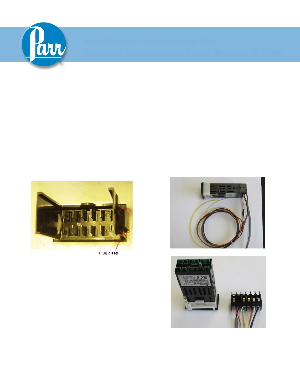
If applicable, remove and discard the black hole 2.
plug on the sloped front panel above the “TEMPERATURE” text. This can be done by pinching
the clasps on the back of the plug from the inside
of the front plate.
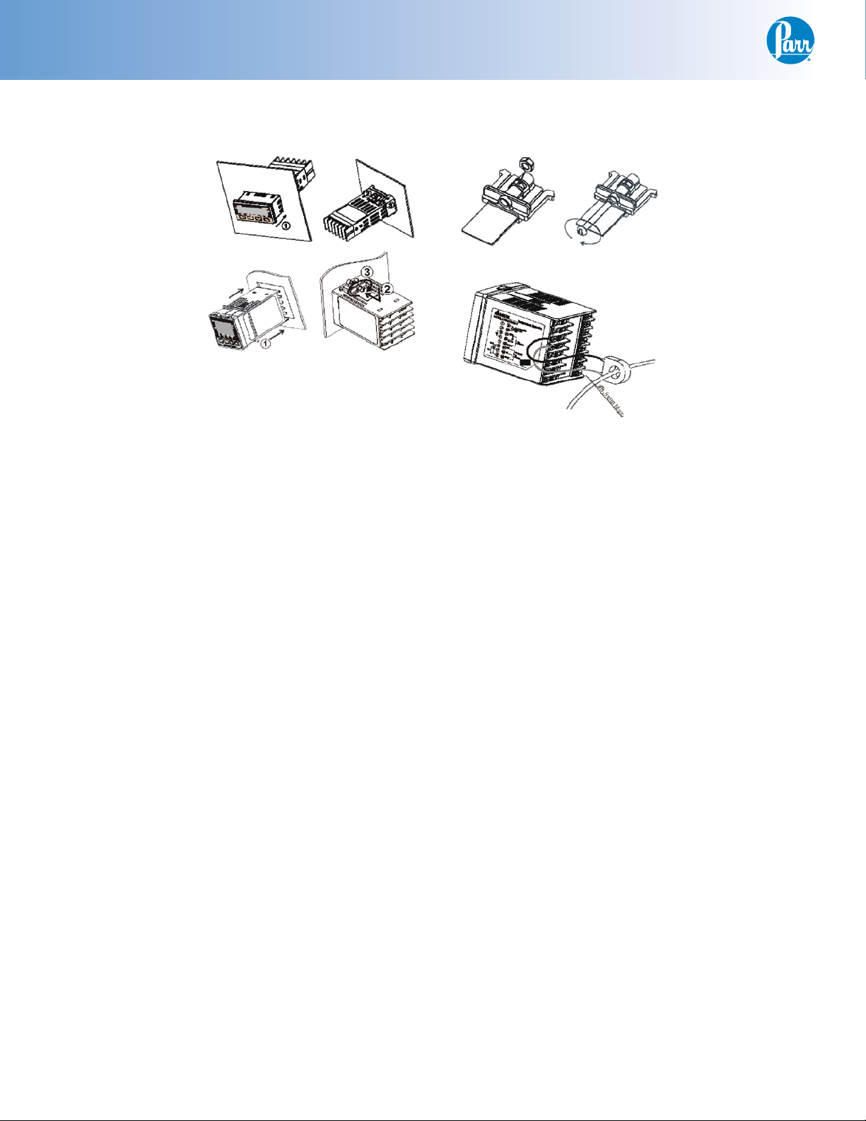
Insert the meter (2082E) through the panel cut-3.
out, from outside in, making sure the rubber
gasket is on the outside of the controller front
panel. (If wires are preinstalled, remove the
terminal connector by releasing the tabs on the
sides of the module and gently pulling the terminal connector off. Reference photos below.) Slide
the white mounting bracket onto the module with
the mounting screws pointing towards the front
panel. Slide the mounting bracket forward until
it touches the controller panel. The clasps on the
mounting bracket should align with the groves
on the module. Gently tighten the screws until
the module is held into place. (If removed, reattach the terminal connector.)
Terminal Connector Removal
Page 2
HTML Installation
Meter Installation in 4848 Reactor Controller (Continued)
Meter Installation Diagram
2
Parr Instrument Company
Page 3
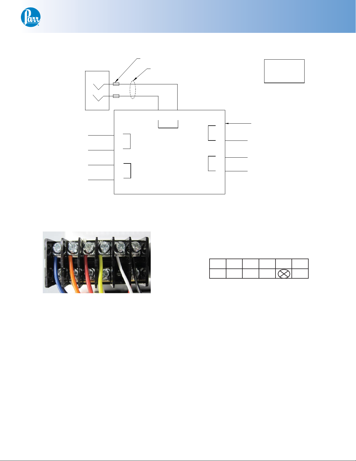
Wiring Installation in 4848 Reactor Controller
BLACK T3
WHITE
6
2 X 1541E BEAD
RED
-
+
WHITE T4
DPM (ETLM)
7
8
2
1
EXTERNAL TEMPERATURE LIMIT
1398E2
4
12
11
2082E
10
YELLOW
9
#7 RED WIRE
FROM 2083E PRIMARY
TEMPERATURE CONTROL
REF
T/C JACK
Example:
T_=Terminal Block
position_
T/C
115V or 230V
ALARM
RS485
1119E SOLID STATE RELAY
(position 3)
T7 BLUE
T6 ORANGE
T2 WHITE
T5 BLACK
Non-latching
alarm
HTML Installation
Picture of 2082E Pin Out
Wiring Diagram for 2082E Meter
7 8 9 10 11 12
1 2 3 4 5 6
2082E Pin Out
(Pin 5 is blank)
www.parrinst.com
3
Page 4

HTML Installation
Wiring Installation in 4848 Reactor
Controller (Continued)
Warning: Take care not to apply too much torque when
tightening down on wires. This can cause them to
weaken and break.
Take the black and white cable, with both ends 1.
stripped, from the kit and attach one end to the
2082E meter. Connect the white wire #6 to pin
11 and black wire #7 to pin 12.
Attach the other stripped end of white wire #6 to
terminal block position #4 and the black wire #7
to terminal block position #3.
Note: The terminal block position can be opened up
using a small fl at head screw driver to release the
tension from the spring inside the block so you can
press the wire against the spring.
Find the free orange wire #1 from the kit and 4.
attach one end to pin 8 on the 2082E meter. The
other end attaches to terminal block position #6.
Find the free blue wire #2 from the kit and attach 5.
one end to pin 7 on the 2082E meter. The other
end attaches to terminal block position #7.
Locate the thermocouple jack on the back of the 6.
4848 Controller labeled “TEMPERATURE INPUT”.
Slip one 1541E bead on the red and the white
wire. Attach the 1398E2 internal thermocouple
wire to the jack by wrapping the wires around
the posts and tightening them.
Wago Terminal Block
Find the free black wire #4 from the kit and at-2.
tach one end to pin 1 on the 2082E meter. The
other end attaches to terminal block position #5.
Find the free white wire #3 from the kit and at-3.
tach one end to pin 2 on the 2082E meter. The
other end attaches to terminal block position #2.
T/C Jack
Locate the 2083E Primary Temperature Meter. 7.
There is a red wire connected between pin 2 and
the 1119E solid state relay (position 3). Remove
the tabbed end of this wire from the 1119E and
attach it to the 2082E ETLM meter on pin 9.
Back of 2083E
Primary Temperature Meter
4
Parr Instrument Company
Page 5

HTML Installation
Locate the free yellow wire #5 from the kit and 8.
attach one end to pin 10 on the 2082E meter. The
other end attaches to the 1119E solid state relay
(position 3).
Pin Outs:
2082E Color: Attaches to:
Pin 1 Black Terminal Block 5
Pin 2 White Terminal Block 2
Pin 3
Pin 4 White T/C jack +
Pin 5
Pin 6 Red T/C jack Pin 7 Blue Terminal Block 7
Pin 8 Orange Terminal Block 6
Pin 9 Red 2083E Primary Temp
Meter
Pin 10 Yellow 1119E SSR (3)
Pin 11 White Terminal Block 4
Pin 12 Black Terminal Block 3
* White (Type – J), Yellow (Type – K), Blue (Type – T),
Black (RTD)
** Red (Type – J, Type – K, Type – T), White (RTD)
SSR Position 3
Final Steps:
Close the controller and replace the two screws on
the top plate. Plug the 4848 controller back in, and
turn it on.
It is useful to check that the settings on the display
are set correctly. Check these against the defaults
listed in the back of these instructions.
www.parrinst.com
5
Page 6

HTML Installation
Factory Default Settings - ETLM
Keys command:
Press “SET” to select 1.
Press return key move to next operation mode2.
Up/Down arrow keys to adjust value or select 3.
type
Main Screen: SV = 375
Press return key and release
Operation
Mode
r-S Run Run/Stop
SP 0** Decimal point position
AL1H 375 Upper-limit alarm 1
AL1L 0 Lower-limit alarm 1
LoC OFF
Out1
** If using a type-J or type-K thermocouple, SV = 0
If using an RTD, SV = 1
Press and hold down “SET” for 5-sec
Select
type/value
- (readonly)
Comment
Lock mode(lock all keys
or only up/down arrow
able to use)
Heater Output %
Operation
Mode
SALA OFF System alarm
CoSH ON Communication write
C-Sl ASCII Format type
C-no 4 Communication address
bPS 9600 Communication baud
LEn 7 Data length setting
PrtY Even Parity bit setting
StoP 1 Stop bit setting
** If using a type-J thermocouple, InPt = J
If using a type-K thermocouple, InPt = K
Select
type/value
Comment
function that able to use
set point from software
rate
High Temperature Module - ETLM
Press “SET” and release
Operation
Mode
At OFF Auto Tuning ON/OFF
HtPd 5 Heat cycle control
tPoF 0 Inaccuracy adjustment
Select
type/value
Comment
Operation
Mode
InPt J** Input type
tPUn C Temperature unit
tP-H 800 Upper-limit temperature
tP-L 0 Lower-limit temperature
CTRL ON/OFF Control mode (ON/OFF,
PROG)
S-HC Heat Heat/Cool control
ALA1 6 Alarm operates when
6
Select
type/value
Parr Instrument Company
Comment
range
range
MANUAL, PID and PID
PV value is higher than
AL1H value
Page 7

This page intentionally left blank.
HTML Installation
www.parrinst.com
7
Page 8

Revision 05/12/11
 Loading...