

Page 1
Installation Instructions for a CAL 9500P Temperature
Controller into an Existing 4840 Controller
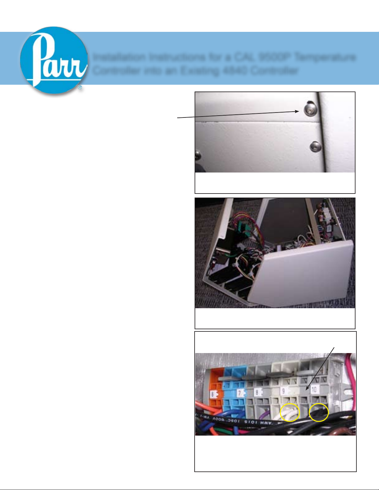
1. Unplug the power cord from the controller.
Remove the two screws from the back side of
the controller (at the top corners). (See Figure 1)
2. Lift the top cover which is hinged at the
bottom front of the case; the assembly will open
like a book. (See Figure 2)
NO. 569M
3. Disconnect all wire connections from the
existing Watlow Temperature Control module.
Remove the green wire from this set of wires,
and discard the black jumper wire.
4. Cut off the spade connectors from the
remaining wires and strip each one to expose
0.25” of wire.
5. Locate the black wire which is currently not
connected to anything, and trace it to terminal
block location 10. Disconnect it from terminal
block location 10, and attach it to terminal block
location 4. (See Figure 3)
6. Locate the white wire which is currently not
connected to anything, and trace it to terminal
block location 9. Disconnect it from terminal
block location 9, and attach it to terminal block
location 3. (See Figure 3)
Top screw at corner
Figure 1
4840 with cover open
Figure 2
Tip: The wire will come out easily after inserting a small
athead screwdriver into the release port.
7. Remove the Watlow temperature controller
from the front panel of the 4840 Controller.
8. Install the adapter plate to the front panel of
the 4840 temperature controller using the screws
provided.
9. Install the Cal 9500P temperature controller
into the adapter plate in the front panel of the
4840 Controller using the plastic retaining cage.
From the front side, the three buttons on the
colored backing should be at the bottom, not the
top. Check the orientation!
If there is more than one black wire on terminal block 10,
locate the one which is currently not attached to anything.
Figure 3
Page 2
Cal 9500P
Installation Instructions
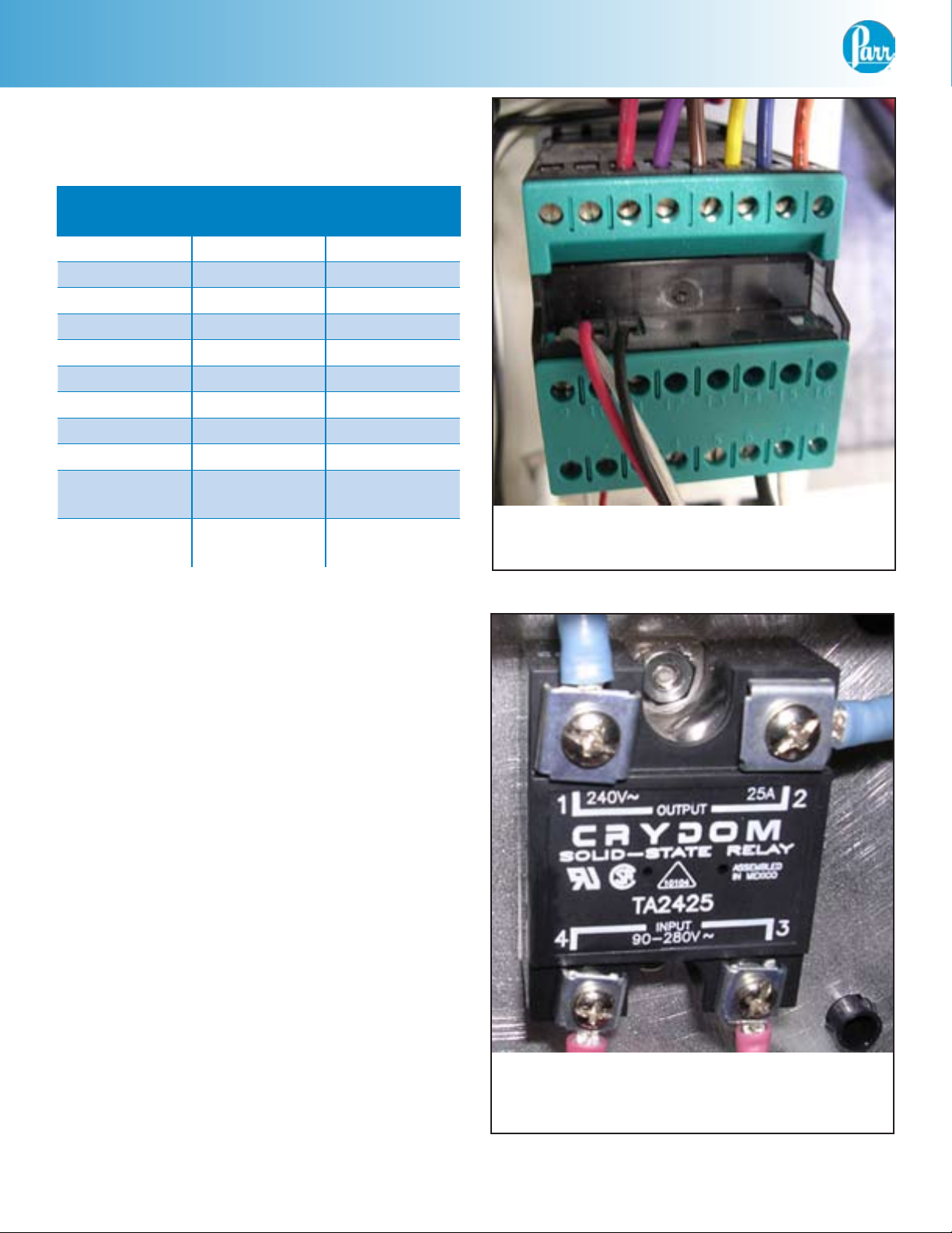
10. Connect the wires of the Cal 9500P
temperature controller as follows: (See Figure 4)
Wire:
Cal Pin #
Position:
Function
Black 7 Power
White 8 Power
Orange 24 High limit
Blue 23 High limit
Brown 21 SVM
Yellow 22 SVM
Red 19 SSR
Purple 20 SSR
T/C White
(Type J)
T/C Red
(Type J)
1 T/C
2 T/C
11. Remove the four wires connected to the
solid state relay on the back panel of the 4840
controller. (See Figure 5)
Back of Cal 9500P with wiring
Figure 4
12. Remove the solid state relay from the back
of the 4840 controller and resistor if present.
Discard the old solid-state relay and resistor.
13. Install the provided solid-state relay (part #:
1119E) on the back panel of the 4840 controller.
(See Figure 6)
14. Attach the short black wire to position 1 of
the relay.
15. Attach the long black wire to position 2 of the
relay.
16. Attach the red wire to position 3 of the relay.
17. Attach the purple (or blue) wire to position 4
of the relay.
Solid state relay for use with Watlow
(to be replaced)
Figure 5
2 Parr Instrument Company
Page 3

18. Trace this purple (or blue) wire to terminal
block location 7 and remove from the terminal
block. Attach this wire to position 20 of the Cal
9500P. (See Figure 6)
19. Optional step to connect RS-232
communication wire: (See Figure 7)
Cal 9500P
Installation Instructions
(#1119E) Solid state relay for use with
Cal 9500P (to be installed)
Figure 6
Connect the white/clear wire of the A1845E
communication harness to position 9 of the
Cal 9500P.
Connect the red wire of the A1845E to
position 10.
Connect the black wire of the A1845E to
position 11.
Mount the 9-pin connector to the rear panel
of the 4840 with the hardware provided. (See
Figure 8)
20. Close the hinged front cover and reinstall
the two retaining screws (removed in step 1).
21. Reconnect power cord to the 4840
Controller.
Back of Cal 9500P with wiring
Figure 7
Back of RS-232 with wiring
Figure 8
www.parrinst.com 3
Page 4

Revision 01/12/10
P
arr Instrument Company
211 53rd Street
Moline, Illinois 61265 USA
Phone: 1-309-762-7716 or 1-800-872-7720
Fax: 1-309-762-9453
E-mail: parr@parrinst.com
http://www.parrinst.com
 Loading...